JP4031104B2 - Stereo camera - Google Patents
Stereo cameraDownload PDFInfo
- Publication number
- JP4031104B2 JP4031104B2JP03928298AJP3928298AJP4031104B2JP 4031104 B2JP4031104 B2JP 4031104B2JP 03928298 AJP03928298 AJP 03928298AJP 3928298 AJP3928298 AJP 3928298AJP 4031104 B2JP4031104 B2JP 4031104B2
- Authority
- JP
- Japan
- Prior art keywords
- camera
- stay
- unit
- base
- cameras
- Prior art date
- Legal status (The legal status is an assumption and is not a legal conclusion. Google has not performed a legal analysis and makes no representation as to the accuracy of the status listed.)
- Expired - Lifetime
Links
- 125000006850spacer groupChemical group0.000claimsdescription20
- 238000000034methodMethods0.000claimsdescription7
- XAGFODPZIPBFFR-UHFFFAOYSA-NaluminiumChemical compound[Al]XAGFODPZIPBFFR-UHFFFAOYSA-N0.000description5
- 229910052782aluminiumInorganic materials0.000description5
- 238000012856packingMethods0.000description4
- 229930040373ParaformaldehydeNatural products0.000description3
- 239000005357flat glassSubstances0.000description3
- 238000003384imaging methodMethods0.000description3
- 239000000463materialSubstances0.000description3
- 230000003287optical effectEffects0.000description3
- 229920006324polyoxymethylenePolymers0.000description3
- 239000000758substrateSubstances0.000description3
- 239000000853adhesiveSubstances0.000description2
- 230000001070adhesive effectEffects0.000description2
- 230000002093peripheral effectEffects0.000description2
- 229910000679solderInorganic materials0.000description2
- RYGMFSIKBFXOCR-UHFFFAOYSA-NCopperChemical compound[Cu]RYGMFSIKBFXOCR-UHFFFAOYSA-N0.000description1
- VYPSYNLAJGMNEJ-UHFFFAOYSA-NSilicium dioxideChemical compoundO=[Si]=OVYPSYNLAJGMNEJ-UHFFFAOYSA-N0.000description1
- 239000011248coating agentSubstances0.000description1
- 238000000576coating methodMethods0.000description1
- 229910052802copperInorganic materials0.000description1
- 239000010949copperSubstances0.000description1
- 230000000694effectsEffects0.000description1
- 239000011521glassSubstances0.000description1
- 238000004519manufacturing processMethods0.000description1
- -1polyoxymethylenePolymers0.000description1
- 239000011347resinSubstances0.000description1
- 229920005989resinPolymers0.000description1
- 238000002834transmittanceMethods0.000description1
Images


Landscapes
- Studio Devices (AREA)
- Stereoscopic And Panoramic Photography (AREA)
- Accessories Of Cameras (AREA)
- Testing, Inspecting, Measuring Of Stereoscopic Televisions And Televisions (AREA)
Description
Translated fromJapanese【0001】
【発明の属する技術分野】
本発明は、カメラ部と該カメラ部から出力される画像信号等を処理する処理回路部とを一体化したステレオカメラに関する。
【0002】
【従来の技術】
近年、ビデオカメラを飛行機や車両等の移動体に搭載して、移動体の高度や位置を計測する技術が開発されている。例えば、特開昭62−88914号公報には、単体のカメラにより取得した画像データのうち撮像点が異なる2つの撮像データに基づいて高度を計測する技術が開示されている。
【0003】
又、最近では、2台のビデオカメラ(ステレオカメラ)で対象物を異なる位置から撮像した一対の画像の相関を求め、同一物体に対する視差からステレオカメラの取付け位置や焦点距離等のカメラパラメータを用いて三角測量により距離や位置を求める、いわゆるステレオ法による画像処理が知られている。
【0004】
【発明が解決しようとする課題】
ところで、上記先行技術には詳述されていないが、一般には、撮像素子を備えるカメラ部は移動体の外部に垂設され、このカメラ部からの画像信号を処理する処理回路部は移動体内部に配置されている。
【0005】
上記カメラ部と上記処理回路部とが比較的離れていると、この両者を接続するケーブルが長くなるためノイズが混入し易く、ノイズ対策を講じる必要があり、構造の複雑化を招く。
【0006】
又、一般にカメラ本体は、機体フレーム等に固設さている構造であるため、その指向方向を任意に変更することができず、例えばステレオカメラにて前方の対象物を認識する場合に据え付けたベースを利用して、側方或いは下方の対象物を認識できるように、カメラの指向方向を変更することができず、取扱性が悪い。
【0007】
本発明は、上記事情に鑑み、耐ノイズ性が良好で、カメラの指向方向を任意に設定することができ、取扱性の良いステレオカメラを提供することを目的とする。
【0008】
【課題を解決するための手段】
上記目的を達成するため本発明による第1のステレオカメラは、撮像素子を有する一対のカメラをカメラステイに固設したカメラ部と該カメラ部からの出力信号を処理すると共に該カメラ部に対して駆動信号を出力する処理回路部とを備え、カメラベースに上記カメラステイと上記処理回路部とを近接した状態で固設し、上記カメラステイの上記両カメラ間の中央部のみを上記カメラベースにステイ取付けスペーサを介して固設したことを特徴とする。
【0009】
第2のステレオカメラは、第1のステレオカメラにおいて、前記カメラステイと前記ステイ取付けスペーサと前記カメラベースとがカメラ筐体に収容されていると共に、前記カメラベースのみが該カメラ筐体に固設されていることを特徴とする。
【0010】
すなわち、第1のステレオカメラでは、カメラ部のカメラステイと処理回路部とをカメラベースに近接した状態で固設したので、この両者間を接続するケーブル長さが短くなり耐ノイズ性が良好になる。更に、前記カメラステイの両カメラ間の中央部のみが前記カメラベースにステイ取付けスペーサを介して固設されているので、両カメラに締結時の無理な力が加わらず、組立時の両カメラの光軸ズレが防止され、又、ステイ取付けスペーサの形状、或いはステイ取付けスペーサに対する上記カメラステイの取付け位置を変えることで、カメラの指向方向を任意に設定することができる。
【0011】
第2のステレオカメラでは、第1のステレオカメラにおいて、カメラ筐体にカメラベースのみを固設したのでカメラ部、処理回路部に無理な力が加えられず製造組立が容易で優れた耐久性を得ることができる。
【0012】
【発明の実施の形態】
以下、図面に基づいて本発明の一実施の形態を説明する。図中の符号1はステレオカメラで、内部に、カメラ部2と処理回路部3とが一体化されたカメラユニット4が収納されている。
【0013】
図4に示すように、上記カメラ部2に設けたカメラステイ7に、メインカメラ5とサブカメラ6とが所定間隔を開けて配設されている。尚、上記カメラステイ7は、1枚のアルミ板を加工して形成したものである。
【0014】
上記両カメラ5,6に設けられているマウント8の背面には、CCD等の撮像素子9を実装する回路基板10(図2参照)が固設され、更にCCD駆動回路等の周辺回路が組み込まれた周辺回路基板11がスペーサ11aを介して固設されている。
【0015】
又、上記両カメラ5,6の各マウント8の前面に突設されたボス8aが、上記カメラステイ7に形成されているマウント取付け窓7a(図2参照)に装着されて、ねじ止めされている。上記各マウント8に形成されているボス8aには、前方からレンズ鏡筒12が螺着されている。上記カメラステイ7の上記両カメラ5,6間の中央部には取付け孔7bが、本実施の形態では5カ所穿設されている。
【0016】
上記カメラステイ7の中央部背面が、カメラベース13の前部中央に、断面H型のステイ取付けスペーサ14を介して当接され、前面より上記取付け孔7bに挿通されたねじにより固定されている。更に、上記カメラベース13の後部に、コネクタ15bを装着したコネクタ取付け板15が垂設されている。
【0017】
上記カメラステイ7は、その中央部のみがカメラベース13にねじ止めされているので、両カメラ5,6に無理な力が加わることがなく、又、上記ステイ取付けスペーサ14の形状を変形することで、カメラを任意の方向へ指向させることが可能となる。
【0018】
又、上記処理回路部3は、上記両撮像素子9からの画像信号を処理する画像処理回路、両画像信号をステレオ処理するステレオ処理回路、上記撮像素子9へ駆動信号を出力するCCD駆動回路等の処理回路が組み込まれた複数の回路基板3aで構成されており、各回路基板3aが基板固定用スペーサ(図示せず)を介して積層された状態で上記カメラベース13にねじ止めされている。尚、上記カメラベース13、基板固定用スペーサは、プラスチックPOM(ポリオキシメチレン)等の比較的軽量で、且つ剛性を有する樹脂製である。
【0019】
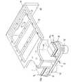
上記カメラユニット4はカメラ筐体16に収納されている。このカメラ筐体16は、シールド性を有する密閉構造であり、ラジコン飛行機等の機体の外壁等に固設される上部プレート16aと、この上部プレート16aに装着される下部ケース16bとに分割可能である。上部プレート16aは比較的厚い板材を加工して形成されており、又、上記下部ケース16bは比較的薄い板材を加工して形成されているもので、この両者はアルミ板等の導電性を有する板材を素材としている。
【0020】
上記カメラユニット4のカメラベース13が上記上部プレート16aにねじ止めされいる。又、上記下部ケース16bの上端外周に、アルミ等の導電性部材を加工して形成したフレーム17が嵌着されてねじ止めされており、その接合部分が半田により閉封されている。更に、このフレーム17と上記上部プレート16aとの接合面に溝が形成されており、この溝に純銅等の導電性部材を素材として形成された導電性パッキン18が装着され、この導電性パッキン18を介して上記上部プレート16aと上記フレーム17との当接面が密着された状態でねじ止めされている。
【0021】
又、上記下部ケース16bの、上記カメラ部2に設けた各カメラ5,6の指向方向に対向する面が開口されており、この開口部にアルミなどの導電性部材を素材とする下部プレート19が嵌着されてねじ止めされ、その接合部分が半田により閉封されている。この下部プレート19の上記両カメラ5,6の前方には入射窓19aが穿設されており、この入射窓19aの前面に平行平面ガラス板20が導電性接着剤を介して接着されている。従って、この平行平面ガラス板20と上記下部プレート19との接合面は上記導電性接着剤により閉封されている。
【0022】
上記平行平面ガラス20は、表面に導電性を有するITOコートが施された石英ガラスであり、透過率を著しく低下させることなく電磁シールドが可能となり、撮像素子9による画像の取り込みが可能になる。
【0023】
又、上記平行平面ガラス20の前面に、アルミなどの導電性部材を素材とする遮光カバー21が装着されている。この遮光カバー21は上記撮像素子9に対する光の入射角を制限し、必要以上の光の入射を防止するもので、この遮光カバー21により上記入射窓の開口面積を必要最小とすることで、電磁波障害をも防止することができる。尚、上記コネクタ取付け板15の外面は上記下部ケース16bを介してフレーム22が取付けられている。上記コネクタ取付け板15にはパッキン取付け用の溝15aが形成されており、上記コネクタ取付け板15と上記フレーム22とで上記下部ケース16bを挟み、上記パッキンを潰して密封する。
【0024】
このような構成によれば、カメラ部2と処理回路部3とがカメラベース13を介して近接した状態で取付けられているので、形状の小型化が図れる。又、この両者間を接続するケーブル長さが短くなるので、耐ノイズ性が向上するばかりでなく、配線作業が容易化し、取扱性が良くなる。
【0025】
又、カメラステイ7は中央部のみが締結されているため、このカメラステイ7に固定されている各カメラ5,6に無理な力が加わることがなく、組立時における両カメラ5,6間の光軸ズレが防止される。
【0026】
更に、上記カメラベース13、基板固定用スペーサをプラスチックPOMを素材に形成することで、剛性を保持しつつ、軽量化を図ることができる。
【0027】
又、コネクタ取付け板15を上記カメラベース13に垂設して処理回路部3及びカメラ部2と一体化したので、これらを一体的に取り出すことができ、回路チェック時の作業性が良くなる。
【0028】
更に、上記カメラステイ7が上記カメラベース13に対してステイ取付けスペーサ14を介して固設されているので、このステイ取付けスペーサ14の形状、或いは該ステイ取付けスペーサ14に対する上記カメラステイ7の取付け位置を変えることで、上記カメラ部2の指向方向を任意に設定することができる。
【0029】
又、カメラユニット4が、導電性を有するカメラ筐体16により完全密閉されているので、電磁シールド性、及び防水性が良く、屋外に設置することが可能となり、取り扱い性が良い。更に、カメラ筐体16内では、上記カメラベース13のみが上記上部プレート16aに固設されている、いわゆるフローティング構造としたため、上記カメラ部2、処理回路部3に無理な力が加えられず、製造組立が容易で耐久性に優れている。
【0030】
【発明の効果】
請求項1記載の発明によれば、カメラベースにステレオカメラのカメラ部と処理回路部とを近接した状態で固設したので、このカメラ部と処理回路部とを接続するケーブル長さが短くなり、耐ノイズ性が良好になるばかりでなく、形状の小型化が実現できる。
【0031】
又、前記カメラステイの中央部を前記カメラベースにステイ取付けスペーサを介して固設したので、締結時に、その両側に配設されている両カメラに無理な力が加わらず、組立時の光軸ズレが防止される。又、ステイ取付けスペーサの形状、或いは該ステイ取付けスペーサに対する上記カメラステイの取付け位置を変えることで、上記カメラ部の指向方向を任意に設定することができるため、取扱性が良くなる。
【図面の簡単な説明】
【図1】カメラ筐体の斜視図
【図2】カメラ筐体に収納されたカメラユニットの図3のA−Aに相当する断面図
【図3】カメラユニットの処理回路部を除いた斜視図
【図4】カメラ部の斜視図
【符号の説明】
1…ステレオカメラ
2…カメラ部
3…回路処理部
5,6…カメラ
7…カメラステイ
9…撮像素子
13…カメラベース
14…スペーサ[0001]
BACKGROUND OF THE INVENTION
The present invention relates to a stereo camera in which a camera unit and a processing circuit unit that processes an image signal output from the camera unit are integrated.
[0002]
[Prior art]
In recent years, a technique for measuring the altitude and position of a moving body by mounting a video camera on a moving body such as an airplane or a vehicle has been developed. For example, Japanese Patent Laid-Open No. 62-88914 discloses a technique for measuring altitude based on two pieces of imaging data having different imaging points among image data acquired by a single camera.
[0003]
Recently, the correlation between a pair of images obtained by capturing an object from different positions with two video cameras (stereo cameras) is obtained, and the camera parameters such as the stereo camera mounting position and focal length are used from the parallax for the same object. Image processing by a so-called stereo method is known in which distance and position are obtained by triangulation.
[0004]
[Problems to be solved by the invention]
By the way, although not described in detail in the above prior art, in general, a camera unit including an image sensor is provided outside the moving body, and a processing circuit unit that processes an image signal from the camera unit is provided inside the moving body. Is arranged.
[0005]
If the camera unit and the processing circuit unit are relatively separated from each other, a cable connecting the two becomes long, so that noise is likely to be mixed in, and it is necessary to take measures against noise, resulting in a complicated structure.
[0006]
In general, since the camera body is fixed to the body frame, the orientation of the camera body cannot be changed arbitrarily. For example, a base installed when a stereo camera recognizes a front object. Since the direction of the camera cannot be changed so that the object on the side or below can be recognized by using, the handleability is poor.
[0007]
In view of the above circumstances, an object of the present invention is to provide a stereo camera that has good noise resistance, can arbitrarily set the directivity direction of the camera, and is easy to handle.
[0008]
[Means for Solving the Problems]
In order to achieve the above object, a first stereo camera according to the present invention includes a camera unit in which a pair of cameras having an image sensor is fixed to a camera stay, an output signal from the camera unit, and the camera unit. A processing circuit unit that outputs a drive signal, the camera stay and the processing circuit unit are fixed to the camera base in a close proximity, andonly the central part of the camera stay between the two cameras is mounted on the camera base. It is characterizedby being fixed via a stay mounting spacer .
[0009]
The second stereo camera is the first stereo camera in which the camera stay, the stay mounting spacer, and the camera base are housed in a camera casing, and only the camera base is fixed to the camera casing. It is characterized by being.
[0010]
That is, in the first stereo camera, the camera stay of the camera unit and the processing circuit unit are fixed in the state of being close to the camera base, so that the length of the cable connecting the two is shortened and the noise resistance is improved. Become.Furthermore, since only the central part between the two cameras of the camera stay is fixed to the camera base via a stay mounting spacer, both the cameras are not subjected to excessive force when fastened, and both cameras during assembly are assembled. The optical axis is prevented from shifting, and the orientation of the camera can be arbitrarily set by changing the shape of the stay mounting spacer or the mounting position of the camera stay relative to the stay mounting spacer.
[0011]
In the second stereo camera,since only the camera base is fixed to the camera case in the first stereo camera, noexcessive force is applied to thecamera part and the processing circuit part, and theassembly is easy and excellent durability. Obtainable.
[0012]
DETAILED DESCRIPTION OF THE INVENTION
Hereinafter, an embodiment of the present invention will be described with reference to the drawings. Reference numeral 1 in the figure denotes a stereo camera, in which a camera unit 4 in which a camera unit 2 and a
[0013]
As shown in FIG. 4, a
[0014]
A circuit board 10 (see FIG. 2) on which an image pickup device 9 such as a CCD is mounted is fixed on the rear surface of the
[0015]
Also, a boss 8a protruding from the front surface of each
[0016]
The rear surface of the central portion of the
[0017]
Since only the central portion of the
[0018]
The
[0019]
The camera unit 4 is housed in a
[0020]
The
[0021]
A surface of the
[0022]
The plane-
[0023]
A
[0024]
According to such a configuration, since the camera unit 2 and the
[0025]
Further, since only the central portion of the
[0026]
Furthermore, by forming the
[0027]
Further, since the
[0028]
Further, since the
[0029]
Further, since the camera unit 4 is completely sealed by the
[0030]
【The invention's effect】
According to the first aspect of the present invention, since the camera unit and the processing circuit unit of the stereo camera are fixed to the camera base in a close proximity, the length of the cable connecting the camera unit and the processing circuit unit is shortened. Not only the noise resistance is improved, but also the shape can be reduced.
[0031]
In addition , since the central portion of the camera stay is fixed to the camera base via astay mounting spacer, an optical force at the time of assembly is not applied to the cameras disposed on both sides at the time of fastening. Misalignment is prevented. Also,stay shape of themounting spacer, or by changing the mounting position of the camera stay for thestay mounting spacer, it is possible to arbitrarily set the directivity direction of the camera unit, the handling property is improved.
[Brief description of the drawings]
FIG. 1 is a perspective view of a camera housing. FIG. 2 is a cross-sectional view of a camera unit housed in the camera housing, corresponding to AA in FIG. 3. FIG. FIG. 4 is a perspective view of the camera unit.
DESCRIPTION OF SYMBOLS 1 ... Stereo camera 2 ...
Claims (2)
Translated fromJapaneseカメラベースに上記カメラステイと上記処理回路部とを近接した状態で固設し、
上記カメラステイの上記両カメラ間の中央部のみを上記カメラベースにステイ取付けスペーサを介して固設した
ことを特徴とするステレオカメラ。A camera unit in which a pair of cameras having an image sensor is fixed to a camera stay, and a processing circuit unit that processes an output signal from the camera unit and outputs a drive signal to the camera unit;
Fix the camera stay and the processing circuit part close to the camera base,
A stereo camera characterized in thatonly the central part between the two cameras of the camera stay is fixed to the camera base via a stay mounting spacer .
ことを特徴とする請求項1記載のステレオカメラ。2. The stereo according to claim 1, wherein the camera stay, the stay mounting spacer, and the camera base are accommodated in a camera casing, and only the camera base is fixed to thecamera casing. camera.
Priority Applications (1)
| Application Number | Priority Date | Filing Date | Title |
|---|---|---|---|
| JP03928298AJP4031104B2 (en) | 1998-02-20 | 1998-02-20 | Stereo camera |
Applications Claiming Priority (1)
| Application Number | Priority Date | Filing Date | Title |
|---|---|---|---|
| JP03928298AJP4031104B2 (en) | 1998-02-20 | 1998-02-20 | Stereo camera |
Publications (2)
| Publication Number | Publication Date |
|---|---|
| JPH11237684A JPH11237684A (en) | 1999-08-31 |
| JP4031104B2true JP4031104B2 (en) | 2008-01-09 |
Family
ID=12548818
Family Applications (1)
| Application Number | Title | Priority Date | Filing Date |
|---|---|---|---|
| JP03928298AExpired - LifetimeJP4031104B2 (en) | 1998-02-20 | 1998-02-20 | Stereo camera |
Country Status (1)
| Country | Link |
|---|---|
| JP (1) | JP4031104B2 (en) |
Families Citing this family (9)
| Publication number | Priority date | Publication date | Assignee | Title |
|---|---|---|---|---|
| US20060061008A1 (en) | 2004-09-14 | 2006-03-23 | Lee Karner | Mounting assembly for vehicle interior mirror |
| JP4679864B2 (en)* | 2004-09-21 | 2011-05-11 | 富士フイルム株式会社 | Stereo camera and stereo camera stay |
| US8698894B2 (en) | 2006-02-07 | 2014-04-15 | Magna Electronics Inc. | Camera mounted at rear of vehicle |
| DE102006050235B4 (en) | 2006-10-17 | 2014-02-13 | Pilz Gmbh & Co. Kg | Camera system for monitoring a room area |
| US9264672B2 (en) | 2010-12-22 | 2016-02-16 | Magna Mirrors Of America, Inc. | Vision display system for vehicle |
| KR101848871B1 (en)* | 2011-08-03 | 2018-04-13 | 엘지전자 주식회사 | Mobile terminal |
| JP5961506B2 (en) | 2012-09-27 | 2016-08-02 | 日立オートモティブシステムズ株式会社 | Stereo camera device |
| JP6511743B2 (en)* | 2014-07-22 | 2019-05-15 | セイコーエプソン株式会社 | Imaging device, medium conveyance device, and printing device |
| WO2022099505A1 (en)* | 2020-11-11 | 2022-05-19 | 深圳市大疆创新科技有限公司 | Vehicle-mounted multi-view assembly, assembling method, and vehicle |
- 1998
- 1998-02-20JPJP03928298Apatent/JP4031104B2/ennot_activeExpired - Lifetime
Also Published As
| Publication number | Publication date |
|---|---|
| JPH11237684A (en) | 1999-08-31 |
Similar Documents
| Publication | Publication Date | Title |
|---|---|---|
| JP6969595B2 (en) | Imaging unit and imaging device | |
| EP3334146B1 (en) | Imaging module and electronic device | |
| JPH11239288A (en) | Case body structure for video camera | |
| TWI605293B (en) | camera | |
| JP7028632B2 (en) | Imaging device | |
| US20150145967A1 (en) | Three dimensional image pick-up device and manufacturing method thereof | |
| JP5381697B2 (en) | Imaging device | |
| US10848649B2 (en) | Imaging device having heat radiation structure | |
| JP4031104B2 (en) | Stereo camera | |
| US9491848B2 (en) | Grounding part, electronic device, imaging device, and grounding part production method | |
| JP2010041709A (en) | Camera module | |
| JP2002118776A (en) | Image pickup device | |
| US7670064B2 (en) | Optical module and optical system | |
| JP5821394B2 (en) | Imaging device | |
| JP2008148253A (en) | Camera module, imaging device, and method of assembling the same | |
| US7750279B2 (en) | Image pickup apparatus and image pickup unit | |
| JP2002218293A (en) | Imaging device | |
| JP2024529292A (en) | The camera module | |
| JP7078151B2 (en) | Imaging unit and imaging device | |
| JP2004134875A (en) | Optical module and method for manufacturing the same, circuit board, and electronic device | |
| JP7646102B2 (en) | Camera Unit | |
| JP6849016B2 (en) | Imaging unit and imaging device | |
| CN102202184B (en) | Photoelectric conversion element unit and imaging device | |
| JP2022113407A (en) | Imaging module | |
| CN115052086A (en) | Camera module and electronic equipment |
Legal Events
| Date | Code | Title | Description |
|---|---|---|---|
| A621 | Written request for application examination | Free format text:JAPANESE INTERMEDIATE CODE: A621 Effective date:20050127 | |
| A977 | Report on retrieval | Free format text:JAPANESE INTERMEDIATE CODE: A971007 Effective date:20070511 | |
| A131 | Notification of reasons for refusal | Free format text:JAPANESE INTERMEDIATE CODE: A131 Effective date:20070522 | |
| A521 | Request for written amendment filed | Free format text:JAPANESE INTERMEDIATE CODE: A523 Effective date:20070704 | |
| TRDD | Decision of grant or rejection written | ||
| A01 | Written decision to grant a patent or to grant a registration (utility model) | Free format text:JAPANESE INTERMEDIATE CODE: A01 Effective date:20070925 | |
| A61 | First payment of annual fees (during grant procedure) | Free format text:JAPANESE INTERMEDIATE CODE: A61 Effective date:20071018 | |
| R150 | Certificate of patent or registration of utility model | Free format text:JAPANESE INTERMEDIATE CODE: R150 | |
| FPAY | Renewal fee payment (event date is renewal date of database) | Free format text:PAYMENT UNTIL: 20101026 Year of fee payment:3 | |
| FPAY | Renewal fee payment (event date is renewal date of database) | Free format text:PAYMENT UNTIL: 20111026 Year of fee payment:4 | |
| FPAY | Renewal fee payment (event date is renewal date of database) | Free format text:PAYMENT UNTIL: 20121026 Year of fee payment:5 | |
| FPAY | Renewal fee payment (event date is renewal date of database) | Free format text:PAYMENT UNTIL: 20121026 Year of fee payment:5 | |
| FPAY | Renewal fee payment (event date is renewal date of database) | Free format text:PAYMENT UNTIL: 20131026 Year of fee payment:6 | |
| R250 | Receipt of annual fees | Free format text:JAPANESE INTERMEDIATE CODE: R250 | |
| R250 | Receipt of annual fees | Free format text:JAPANESE INTERMEDIATE CODE: R250 | |
| S531 | Written request for registration of change of domicile | Free format text:JAPANESE INTERMEDIATE CODE: R313531 | |
| R350 | Written notification of registration of transfer | Free format text:JAPANESE INTERMEDIATE CODE: R350 | |
| R250 | Receipt of annual fees | Free format text:JAPANESE INTERMEDIATE CODE: R250 | |
| R250 | Receipt of annual fees | Free format text:JAPANESE INTERMEDIATE CODE: R250 | |
| R250 | Receipt of annual fees | Free format text:JAPANESE INTERMEDIATE CODE: R250 | |
| EXPY | Cancellation because of completion of term |