JP4030779B2 - Electric wire for automobile and manufacturing method thereof - Google Patents
Electric wire for automobile and manufacturing method thereofDownload PDFInfo
- Publication number
- JP4030779B2 JP4030779B2JP2002079661AJP2002079661AJP4030779B2JP 4030779 B2JP4030779 B2JP 4030779B2JP 2002079661 AJP2002079661 AJP 2002079661AJP 2002079661 AJP2002079661 AJP 2002079661AJP 4030779 B2JP4030779 B2JP 4030779B2
- Authority
- JP
- Japan
- Prior art keywords
- twisted
- wire
- twist
- electric wire
- signal
- Prior art date
- Legal status (The legal status is an assumption and is not a legal conclusion. Google has not performed a legal analysis and makes no representation as to the accuracy of the status listed.)
- Expired - Fee Related
Links
- 238000004519manufacturing processMethods0.000titleclaimsdescription16
- 238000000576coating methodMethods0.000claimsdescription22
- 239000011248coating agentSubstances0.000claimsdescription20
- 238000009413insulationMethods0.000claimsdescription13
- 239000011295pitchSubstances0.000description21
- 239000004020conductorSubstances0.000description17
- 238000000034methodMethods0.000description11
- 239000005020polyethylene terephthalateSubstances0.000description9
- 229920000139polyethylene terephthalatePolymers0.000description9
- RYGMFSIKBFXOCR-UHFFFAOYSA-NCopperChemical compound[Cu]RYGMFSIKBFXOCR-UHFFFAOYSA-N0.000description8
- 239000000463materialSubstances0.000description7
- 229910052802copperInorganic materials0.000description6
- 239000010949copperSubstances0.000description6
- 239000004800polyvinyl chlorideSubstances0.000description6
- 239000000853adhesiveSubstances0.000description4
- 230000001070adhesive effectEffects0.000description4
- 238000010586diagramMethods0.000description4
- 229920000915polyvinyl chloridePolymers0.000description4
- 239000000956alloySubstances0.000description3
- 229910052782aluminiumInorganic materials0.000description3
- XAGFODPZIPBFFR-UHFFFAOYSA-NaluminiumChemical compound[Al]XAGFODPZIPBFFR-UHFFFAOYSA-N0.000description3
- 230000004927fusionEffects0.000description3
- 229910052751metalInorganic materials0.000description3
- 239000004698PolyethyleneSubstances0.000description2
- 239000002390adhesive tapeSubstances0.000description2
- 150000001336alkenesChemical class0.000description2
- 239000011889copper foilSubstances0.000description2
- 230000000694effectsEffects0.000description2
- 239000007769metal materialSubstances0.000description2
- JRZJOMJEPLMPRA-UHFFFAOYSA-NolefinNatural productsCCCCCCCC=CJRZJOMJEPLMPRA-UHFFFAOYSA-N0.000description2
- -1polyethylenePolymers0.000description2
- 229920000573polyethylenePolymers0.000description2
- 229920005672polyolefin resinPolymers0.000description2
- 229920005989resinPolymers0.000description2
- 239000011347resinSubstances0.000description2
- BFKJFAAPBSQJPD-UHFFFAOYSA-NtetrafluoroetheneChemical groupFC(F)=C(F)FBFKJFAAPBSQJPD-UHFFFAOYSA-N0.000description2
- 230000000903blocking effectEffects0.000description1
- 230000006866deteriorationEffects0.000description1
- 239000006260foamSubstances0.000description1
- 239000011888foilSubstances0.000description1
- 230000001939inductive effectEffects0.000description1
- 239000002184metalSubstances0.000description1
- 150000002739metalsChemical class0.000description1
Images


Landscapes
- Insulated Conductors (AREA)
- Communication Cables (AREA)
- Processing Of Terminals (AREA)
Description
Translated fromJapanese【0001】
【発明の属する技術分野】
本発明は、自動車用電線及びその製造方法に関し、特にコネクタへの自動化された一括接続に適する自動車用電線及びその製造方法に関するものである。
【0002】
【従来の技術】
自動車では、電装品等への電気的接続のために各種の電線が使用されている。これらの電線のうち、スピーカーやオーディオ制御回路等に使用されている、いわゆるツイスト線は、2本の絶縁被覆付信号線(ディスクリート線)を所定の撚りピッチ(例えば35〜45mm程度)で対撚りした構造をしており、誘導ノイズ対策を行っている。図1に従来のツイスト線1を示す。図中2は絶縁被覆付信号線で導線2aと絶縁被覆2bからなる。導線2aの断面積の大きさ(以下、導体サイズとも称する)は0.3〜1.25mm2程度である。
【0003】
ところで、近時は自動車用ワイヤハーネスにおいて電線とコネクタとの接続を自動化することが行われている。ところが、この接続の自動化にあたり、図1に示すツイスト電線構造は次のような理由により自動化の阻害要因となっている。
先ず、ツイスト線は2本のディスクリート線が隣同士でくっついたような構造であるため、コネクタのピッチに不適合となっている。例えば、導体サイズが0.3mm2の導線間の間隔は1.1〜1.3mmであるのに対し、コネクタのピッチは2.0〜4.0mmとなっている。
また、ツイスト線を調尺、切断した際に2本のディスクリート線の向きがランダムとなり、いずれの線が上下左右どの位置にくるか予想がつかない。すなわち、調尺、切断の位置によって、2本のディスクリート線の位置関係が様々なものとなる。
【0004】
一方、自動車用電線の中には外部ノイズを遮断し良好な信号を伝送する目的でシールド部材を設けたものがある。図2に従来のシールド電線の構造例を示す。
従来のシールド電線11は、複数の絶縁被覆付信号線12とドレイン線13を撚り合わせたものの周りをシールド層14で被覆し、さらにその周りを絶縁性シース15で被覆した構造が一般的である。信号線12は導線12aとその周りを被覆する絶縁被覆12bから構成されている。
【0005】
このような構成において、外部ノイズはシールド層14により遮蔽され、その遮蔽されたノイズはドレイン線13を通じて外部のアースへ落とされる。そして各種電装品には信号線12を介して良好な信号が供給されるようになっている。
【0006】
ところが、図2に示す従来のシールド電線11では、信号線12とドレイン線13が集合撚線構造となっているため、端末加工(コネクタ端子との接続)がやりにくく、端末加工に時間がかかっていた。また、端末加工長として絶縁性シース5とシールド層14の剥ぎ取り長が80mm程度必要なことから、端末でのシールド性能が悪化する問題があった。そしてこのような構造も、コネクタと電線との接続の自動化において自動化の阻害要因となっていた。
【0007】
【発明が解決しようとする課題】
本発明は、このような従来技術の問題点を解消し、コネクタへの自動化による一括接続に適した自動車用電線(ツイスト線)及びその製造方法を提供することをその課題とする。
また、本発明は、シールド性能に優れ、コネクタへの自動化による一括接続に適したフラットタイプの自動車用電線及びその製造方法を提供することを別の課題とする。
【0008】
【課題を解決するための手段】
本発明によれば、上記課題は下記の技術的手段により解決される。
(1)2本の絶縁被覆付信号線を所定の撚りピッチで対撚りしたツイスト部と、該ツイスト部の端部に形成された非ツイスト部とを長さ方向に交互に設けるとともに、該2本の絶縁被覆付信号線を1組として横方向に複数組並列させ、該ツイスト部と該非ツイスト部との間にそれぞれ固定テープを貼着した長尺状の構造体に対し、該非ツイスト部及び各組の間の適所を切断することにより自動車用電線を製造することを特徴とする自動車用電線の製造方法。
(2)2本の絶縁被覆付信号線を所定の撚りピッチで対撚りしたツイスト部と、該ツイスト部の端部に形成された非ツイスト部とを長さ方向に交互に設けた少なくとも1以上の信号線対に、1本のドレイン線を並列させ、該1以上の信号線対とこれに並列させた1本のドレイン線を1組として横方向に複数組並列させ、該信号線対のツイスト部と該非ツイスト部との間に相当する部分を、該ドレイン線を含めて固定テープを貼着し、さらに該信号線のツイスト部とこれと並列する該ドレイン線の部分にシールド部材を設けた長尺の構造体に対し、該非ツイスト部に相当する部分及び各組の間の適所を切断することにより自動車用電線を製造することを特徴とする自動車用電線の製造方法。
【0009】
【発明の実施の形態】
以下、本発明の実施の形態を好ましい実施例により説明する。
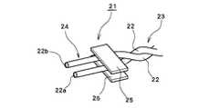
図3に本発明の一実施例に係る自動車用電線(以下、ツイスト線とも称する)の構造を模式的に示す。
本実施例のツイスト線21は、2本の絶縁被覆付信号線22を所定の撚りピッチで対撚りしたツイスト部23と、該ツイスト部23の端部に形成された非ツイスト部24からなり、ツイスト部23と非ツイスト部24との間に固定テープ25を貼着することにより、接続端における信号線22同士の間隔を保持するとともに、ツイストの撚戻りをしたものである。すなわち、非ツイスト部24においては、2本の信号線(ディスクリート線)22は互いに平行に配置される。非ツイスト部24における信号線22の導線22a同士の線間ピッチは、接続すべきコネクタのピッチと一致させる。信号線22は導体22aと絶縁被覆22bからなる。
【0010】
信号線22の外径は用途に応じて適宜設定されるが、通常φ0.85〜φ0.95mm程度である。導線22aの断面積(導体サイズ)は0.13〜0.22mm2程度である。導線22aとしては、銅、アルミニウム、Snメッキ銅等の各種金属・合金材料を使用することができ、撚線でも単線でもよい。
信号線22の絶縁被覆22bとしては、ポリ塩化ビニル(PVC)、ポリエチレン(発泡系を含む)、ハロゲンフリー材、テトラフロロエチレン等の各種樹脂材料を用いることができる。絶縁被覆22bの厚さは導線22aの導体サイズに応じて適宜設定される。
【0011】
ツイスト部23における撚りピッチは35〜45mm程度に設定されるが、これに限定されない。ツイスト部23の長さは用途に応じて設定されるが、通常100〜2000mm程度である。
非ツイスト部24における信号線22の導線22a同士の線間ピッチは上述のようにコネクタピッチと一致させるが、通常2.0〜4.0mm程度である。非ツイスト部24における信号線22の長さは30〜40mm程度である。
【0012】
上下の固定テープ25は貼着され、その状態でコネクタへ接続され、接続後も貼着されたままである。固定テープ25の幅は6〜162mm程度、長さは10〜30mm程度である。固定テープ25による貼着は、粘着テープの使用による接着、融着等の方法を用いることができる。固定テープ25の材料としては、例えばオレフィン系接着剤付PET、ポリ塩化ビニル、PET/ポリ塩化ビニル、PET/ポリオレフィン系樹脂等を用いることができる。
【0013】
上記のような構造のツイスト線21によれば、端部が非ツイスト部24となっており、該非ツイスト部24における信号線22の導線22a同士の線間ピッチが、接続すべきコネクタピッチと一致しており、かつ信号線22同士の位置関係も一定となっているので、自動車用ワイヤハーネスにおける電線とコネクタの接続の自動化に適したものとなる。
【0014】
次に、上記のような構造のツイスト線21の製造方法について図4を参照して述べる。
図4に示すように長さ方向に対してツイスト部23と非ツイスト部24が交互に形成された長尺の構造体26を作製しておく。ツイスト部23と非ツイスト部24との組合せの個数は任意の数とすることができる。また構造体26において図示の例ではツイスト線21は4本並列に配置されているが、任意の本数とすることができる。ツイスト部23と非ツイスト部24との間には固定テープ25を図示のようにツイスト線21の幅方向に配置する。この状態で切断線27のところで切断した後、さらに固定テープ25をツイスト線21ごとに切断することにより、同時に多数のツイスト線21が製造できる。切断の順序は逆としてもよい。
【0015】
次に、本発明の別の実施例に係る自動車用電線を説明する。図5は本実施例の自動車用電線(以下シールド電線とも称する)の構造を示す斜視図である。
図5に示すように、本実施例のシールド電線31は、2本の絶縁被覆付信号線32を所定の撚りピッチで対撚りしたツイスト部33と、該ツイスト部33の端部に形成された非ツイスト部34からなる信号線対35を2つと、ドレイン線36とを並列させてなり、該信号線対35のツイスト部33と該非ツイスト部34との間に相当する部分(シールドレス部)を、該ドレイン線36を含めて固定テープ37を貼着することにより信号線32の導線32a同士及びドレイン線36の間隔を保持するとともに、ツイストの撚戻りを防止し、さらに該信号線32のツイスト部34とこれと並列する該ドレイン線36の部分にシールド部材38を設けたものである。すなわち、非ツイスト部34においては、4本の信号線(ディスクリート線)32とドレイン線36は互いに平行に配置される。非ツイスト部34において信号線32の導線32a同士及びドレイン線36の線間ピッチは、接続すべきコネクタのピッチと一致させる。信号線32は導体32aと絶縁被覆32bからなる。
【0016】
信号線32の外径は用途に応じて適宜設定されるが、通常φ0.85〜φ0.95mm程度である。導線32aの断面積(導体サイズ)は0.13〜0.22mm2程度である。導線32aとしては、銅、アルミニウム、Snメッキ銅等の各種金属・合金材料を使用することができ、撚線でも単線でもよい。
信号線32の絶縁被覆32bとしては、ポリ塩化ビニル(PVC)、ポリエチレン(発泡系を含む)、ハロゲンフリー材、テトラフロロエチレン等の各種樹脂材料を用いることができる。絶縁被覆32bの厚さは導線32aの導体サイズに応じて適宜設定される。
【0017】
ツイスト部33における撚りピッチは35〜45mm程度に設定されるが、これに限定されない。ツイスト部23の長さは用途に応じて設定されるが、通常100〜2000mm程度である。本実施例では、2つの信号線対35の撚り位置は同じとなっているが、互いに異なるようにしてもよく、その場合、シールド特性をより向上させることができる。
非ツイスト部34における信号線32の導線32a同士及びドレイン線36の線間ピッチは、上述のように、接続すべきコネクタピッチと一致させるが、通常2.0〜4.0mm程度である。非ツイスト部24における信号線22の長さは30〜40mm程度と、図2に示す従来のシールド電線(80mm程度)に比べ大幅に短くすることができる。
また、本実施例では信号線対35の数は2つであるが、用途に応じて1つ又は3つ以上の任意の数とすることができる。
【0018】
ドレイン線36は軟銅、Snメッキ銅等の金属・合金材料で構成され、撚線でも単線でもよい。ドレイン線36の導体サイズは0.22〜0.3mm2程度であることが好ましい。
【0019】
固定テープ37は、図5では端部同士が貼着されていないが、実際には貼着され、その状態でコネクタへ接続され、接続後も貼着されたままである。固定テープ37の幅は6〜162mm程度、長さは信号線対35の数に応じて適宜設定される。粘着テープの使用による接着、融着等の方法を用いることができる。固定テープ37の材料としては、例えばオレフィン系接着剤付PET、ポリ塩化ビニル、PET/ポリ塩化ビニル、PET/ポリオレフィン系樹脂等を用いることができる。
【0020】
シールド部材38としては、シールド効果を有する材料が使用されるが、シールドテープの使用が好ましい。シールドテープとしては、具体的にはSnメッキ銅箔PETテープ、Snメッキ銅箔/PETテープ、アルミニウム箔/PETテープ等が使用でき、その厚さは15〜21μm程度である。シールドテープの取付は、接着剤(導電性接着剤を含む)による接着、融着等の方法を用いることができる。シールド部材38は上下両面から取り付ける。
【0021】
上記のような構造のシールド電線31によれば、端部が非ツイスト部34でかつシールドレス部となっており、該シールドレス部における信号線32の導線32a同士及びドレイン線36の線間ピッチが、接続すべきコネクタピッチと一致しており、かつ信号線32同士及びドレイン線36の位置関係も一定となっているので、自動車用ワイヤハーネスにおける電線とコネクタの接続の自動化に適したものとなる。
また、端部のシールドレス部が図2に示す従来のシールド電線に比べ大幅に短くて済むので端部におけるシールド劣化がなくなり、シールド性能が向上する。
【0022】
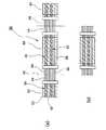
次に、上記のような構造のシールド電線31の製造方法について図6を参照して述べる。
図6(a)に示すように長さ方向に対してツイスト部33と非ツイスト部34が長さ方向に交互に形成された2本の絶縁被覆付信号線32からなる信号線対35を複数(図示の例では2つであるが任意の数とすることができる)並置するとともに、ドレイン線36も並置したものを1組として、1組又は複数組(図示の例では1組であるが任意の組数とすることができる)並列させた長尺の構造体39を作製しておく。ツイスト部33と非ツイスト部34との組合せの個数も任意の数とすることができる。ツイスト部33と非ツイスト部34との間及びその位置に対応するドレイン線36部分には固定テープ37を図示のように幅方向に配置する。この状態で切断線40のところで切断する。信号線対35とドレイン線36からなる組が複数ある場合は、切断線39のところでの切断の後、その組同士の間を切断する。これにより多数のシールド電線31が同時に得られる(図6(b))。切断の順序は逆としてもよい。
【0023】
【発明の効果】
本発明によれば、前記構成及び手法を採用したので、コネクタへの自動化による一括接続に適した自動車用電線(ツイスト線)及びその製造方法を提供することが可能となる。
また、本発明によれば、シールド性能に優れ、コネクタへの自動化による一括接続に適したフラットタイプの自動車用電線及びその製造方法を提供することが可能となる。
【図面の簡単な説明】
【図1】従来のツイスト線の構造を示す図である。
【図2】従来のシールド電線の構造を示す断面図である。
【図3】本発明の一実施例に係るツイスト線の構造を示す図である。
【図4】図2に示すツイスト線の製造方法の説明図である。
【図5】本発明の別の実施例に係るシールド電線の構造を示す図である。
【図6】図5に示すシールド電線の製造方法の説明図である。
【符号の説明】
21 自動車用電線(ツイスト線)
22 絶縁被覆付信号線
22a 導線
22b 絶縁被覆
23 ツイスト部
24 非ツイスト部
25 固定テープ
26 構造体
27 切断線
31 自動車用電線(シールド電線)
32 絶縁被覆付信号線
32a 導線
32b 絶縁被覆
33 ツイスト部
34 非ツイスト部
35 信号線対
36 ドレイン線
37 固定テープ
38 シールド部材
39 構造体
40 切断線[0001]
BACKGROUND OF THE INVENTION
The present invention relates to an automobile electric wire and a manufacturing method thereof, and more particularly to an automobile electric wire suitable for automated batch connection to a connector and a manufacturing method thereof.
[0002]
[Prior art]
In automobiles, various electric wires are used for electrical connection to electrical components. Among these electric wires, so-called twisted wires used for speakers, audio control circuits, etc. are twisted in pairs with a predetermined twist pitch (for example, about 35 to 45 mm) of two signal wires with insulation coating (discrete wires). The structure is designed to prevent inductive noise. FIG. 1 shows a conventional twisted wire 1. In the figure,
[0003]
By the way, recently, it has been performed to automate the connection between electric wires and connectors in an automobile wire harness. However, in automating this connection, the twisted electric wire structure shown in FIG. 1 is an obstacle to automation for the following reasons.
First, since the twisted wire has a structure in which two discrete wires are adjacent to each other, it is incompatible with the connector pitch. For example, the distance between conductors having a conductor size of 0.3 mm2 is 1.1 to 1.3 mm, while the connector pitch is 2.0 to 4.0 mm.
Also, when the twisted line is adjusted and cut, the direction of the two discrete lines becomes random, and it is impossible to predict which line will be in the upper, lower, left or right position. That is, the positional relationship between the two discrete lines varies depending on the adjustment and cutting positions.
[0004]
On the other hand, some electric wires for automobiles are provided with a shield member for the purpose of blocking external noise and transmitting a good signal. FIG. 2 shows an example of the structure of a conventional shielded wire.
The conventional shielded
[0005]
In such a configuration, external noise is shielded by the
[0006]
However, in the conventional shielded
[0007]
[Problems to be solved by the invention]
An object of the present invention is to solve such problems of the prior art and provide an automobile electric wire (twisted wire) suitable for batch connection by automation to a connector and a method for manufacturing the same.
Another object of the present invention is to provide a flat-type automobile electric wire excellent in shielding performance and suitable for batch connection by automation to a connector, and a method for manufacturing the same.
[0008]
[Means for Solving the Problems]
According to the present invention, the above problem is solved by the following technical means.
(1) A twist portion obtained by twisting two signal wires with insulation coating at a predetermined twist pitch and a non-twist portion formed at an end of the twist portion are alternately provided in the length direction, and the 2 A plurality of sets of signal lines with insulating coatings are arranged in parallel in the horizontal direction, and the non-twisted portion and the long-shaped structure in which a fixing tape is adhered between the twisted portion and the non-twisted portion, A method of manufacturing an automotive electric wire, comprising: manufacturing an automotive electric wire by cutting an appropriate place between each set.
(2 ) At least one or more in which twist portions obtained by twisting two signal wires with insulation coating at a predetermined twist pitch and non-twist portions formed at the ends of the twist portions are alternately provided in the length direction. One signal line pair is arranged in parallel, and one or more signal line pairs and one drain line arranged in parallel to the signal line pair are arranged in parallel as a set, and a plurality of sets of the signal line pairs are arranged in parallel. A fixing tape including the drain wire is attached to a portion corresponding to the portion between the twisted portion and the non-twisted portion, and a shield member is provided on the twisted portion of the signal line and the portion of the drain wire parallel to the signal wire. A method for producing an automobile electric wire, comprising: producing an electric wire for an automobile by cutting a portion corresponding to the non-twisted portion and an appropriate position between each set with respect to the long structure.
[0009]
DETAILED DESCRIPTION OF THE INVENTION
The preferred embodiments of the present invention will be described below.
FIG. 3 schematically shows the structure of an automotive electric wire (hereinafter also referred to as a twisted wire) according to an embodiment of the present invention.
The
[0010]
The outer diameter of the
As the insulating coating 22b of the
[0011]
Although the twist pitch in the
The line pitch between the
[0012]
The upper and
[0013]
According to the twisted
[0014]
Next, a method for manufacturing the twisted
As shown in FIG. 4, a
[0015]
Next, an automotive electric wire according to another embodiment of the present invention will be described. FIG. 5 is a perspective view showing a structure of an automobile electric wire (hereinafter also referred to as a shielded electric wire) according to the present embodiment.
As shown in FIG. 5, the shielded electric wire 31 of this embodiment is formed at the twisted
[0016]
The outer diameter of the
As the insulating coating 32b of the
[0017]
Although the twist pitch in the
As described above, the pitch between the conductors 32a of the
In the present embodiment, the number of signal line pairs 35 is two, but may be any number of one or three or more depending on the application.
[0018]
The
[0019]
Although the end portions of the fixing
[0020]
As the
[0021]
According to the shielded electric wire 31 having the above-described structure, the end portion is the
Further, since the shield dress portion at the end portion is significantly shorter than the conventional shielded wire shown in FIG. 2, the shield deterioration at the end portion is eliminated, and the shield performance is improved.
[0022]
Next, a method for manufacturing the shielded electric wire 31 having the above structure will be described with reference to FIG.
As shown in FIG. 6A, a plurality of signal line pairs 35 each including two insulation-coated
[0023]
【The invention's effect】
According to this invention, since the said structure and method were employ | adopted, it becomes possible to provide the electric wire for motor vehicles (twist wire) suitable for the batch connection by the automation to a connector, and its manufacturing method.
In addition, according to the present invention, it is possible to provide a flat type automotive electric wire excellent in shielding performance and suitable for batch connection by automation to a connector, and a manufacturing method thereof.
[Brief description of the drawings]
FIG. 1 is a diagram showing a structure of a conventional twisted wire.
FIG. 2 is a cross-sectional view showing the structure of a conventional shielded wire.
FIG. 3 is a diagram illustrating a structure of a twist line according to an embodiment of the present invention.
4 is an explanatory diagram of a method for manufacturing the twisted wire shown in FIG. 2. FIG.
FIG. 5 is a view showing the structure of a shielded electric wire according to another embodiment of the present invention.
6 is an explanatory diagram of a method for manufacturing the shielded wire shown in FIG. 5. FIG.
[Explanation of symbols]
21 Automotive wire (twisted wire)
22 Insulated
32 Signal line 32a with insulation coating Conductive wire
Claims (2)
Translated fromJapanesePriority Applications (1)
| Application Number | Priority Date | Filing Date | Title |
|---|---|---|---|
| JP2002079661AJP4030779B2 (en) | 2002-03-20 | 2002-03-20 | Electric wire for automobile and manufacturing method thereof |
Applications Claiming Priority (1)
| Application Number | Priority Date | Filing Date | Title |
|---|---|---|---|
| JP2002079661AJP4030779B2 (en) | 2002-03-20 | 2002-03-20 | Electric wire for automobile and manufacturing method thereof |
Publications (2)
| Publication Number | Publication Date |
|---|---|
| JP2003281944A JP2003281944A (en) | 2003-10-03 |
| JP4030779B2true JP4030779B2 (en) | 2008-01-09 |
Family
ID=29229039
Family Applications (1)
| Application Number | Title | Priority Date | Filing Date |
|---|---|---|---|
| JP2002079661AExpired - Fee RelatedJP4030779B2 (en) | 2002-03-20 | 2002-03-20 | Electric wire for automobile and manufacturing method thereof |
Country Status (1)
| Country | Link |
|---|---|
| JP (1) | JP4030779B2 (en) |
Families Citing this family (15)
| Publication number | Priority date | Publication date | Assignee | Title |
|---|---|---|---|---|
| US9685259B2 (en) | 2009-06-19 | 2017-06-20 | 3M Innovative Properties Company | Shielded electrical cable |
| WO2010148165A2 (en) | 2009-06-19 | 2010-12-23 | 3M Innovative Properties Company | Shielded electrical cable |
| JP2011014393A (en)* | 2009-07-02 | 2011-01-20 | Yazaki Corp | Shielded electric wire |
| US10147522B2 (en) | 2010-08-31 | 2018-12-04 | 3M Innovative Properties Company | Electrical characteristics of shielded electrical cables |
| CA2809345A1 (en) | 2010-08-31 | 2012-03-08 | 3M Innovative Properties Company | Connector arrangements for shielded electrical cables |
| US12205732B2 (en) | 2010-08-31 | 2025-01-21 | 3M Innovative Properties Company | Shielded electric cable |
| EP3200202A1 (en) | 2010-08-31 | 2017-08-02 | 3M Innovative Properties Company | Shielded electrical cable in twinaxial configuration |
| EP2522022A1 (en) | 2010-08-31 | 2012-11-14 | 3M Innovative Properties Company | Shielded electrical ribbon cable with dielectric spacing |
| CA2809044A1 (en) | 2010-08-31 | 2012-03-08 | 3M Innovative Properties Company | Shielded electrical cable |
| WO2012030365A1 (en) | 2010-08-31 | 2012-03-08 | 3M Innovative Properties Company | High density shielded electrical cable and other shielded cables, systems, and methods |
| US8859901B2 (en) | 2010-09-23 | 2014-10-14 | 3M Innovative Properties Company | Shielded electrical cable |
| JP5675329B2 (en) | 2010-12-27 | 2015-02-25 | 矢崎総業株式会社 | Conductive path shield structure and wire harness |
| JP5657179B1 (en)* | 2013-02-23 | 2015-01-21 | 古河電気工業株式会社 | Connection structure, connector, method for manufacturing connection structure, electric wire connection structure, and tubular terminal |
| JP5881806B2 (en)* | 2014-11-28 | 2016-03-09 | 矢崎総業株式会社 | Conductive path shield structure and wire harness |
| JP2017091855A (en)* | 2015-11-11 | 2017-05-25 | 住友電装株式会社 | Wire harness |
- 2002
- 2002-03-20JPJP2002079661Apatent/JP4030779B2/ennot_activeExpired - Fee Related
Also Published As
| Publication number | Publication date |
|---|---|
| JP2003281944A (en) | 2003-10-03 |
Similar Documents
| Publication | Publication Date | Title |
|---|---|---|
| JP4030779B2 (en) | Electric wire for automobile and manufacturing method thereof | |
| JP3644631B2 (en) | Shielded cable | |
| CA1202094A (en) | Flat cable of assembled modules and method of manufacture | |
| US20050029006A1 (en) | Signal transmission cable terminal device and data transmission method using signal transmission cable | |
| JP4044805B2 (en) | Flat shielded cable | |
| CA2374932A1 (en) | Cable assembly with molded stress relief and method for making the same | |
| JP4044766B2 (en) | Flat shielded cable | |
| US5132489A (en) | Shielded electric cable | |
| US12230414B2 (en) | Vehicle cable | |
| JP2005032583A (en) | Shielded electric wires for automobiles | |
| JP2003045240A (en) | Shielded flat wire | |
| KR20200041794A (en) | Automotive Communications Cable | |
| JP3691394B2 (en) | Shielded cable | |
| JP2003242840A (en) | Shielded cable | |
| CN203931563U (en) | Multi-core cable | |
| US20190096547A1 (en) | Differential transmission cable and wire harness | |
| CN113302706A (en) | Ethernet cable | |
| EP0784327A1 (en) | Transmission line cable | |
| JP4086243B2 (en) | Twisted pair cable | |
| JP2003223816A (en) | Flat shielded cable | |
| JP4345950B2 (en) | Shielded cable | |
| JPH10125138A (en) | Combination structure of shielded wires | |
| JP2002208321A (en) | Shielded cable | |
| JP3680604B2 (en) | Shielded wire | |
| JP2005197036A (en) | Shielded cable |
Legal Events
| Date | Code | Title | Description |
|---|---|---|---|
| A621 | Written request for application examination | Free format text:JAPANESE INTERMEDIATE CODE: A621 Effective date:20040720 | |
| RD03 | Notification of appointment of power of attorney | Free format text:JAPANESE INTERMEDIATE CODE: A7423 Effective date:20050209 | |
| A521 | Written amendment | Free format text:JAPANESE INTERMEDIATE CODE: A523 Effective date:20050311 | |
| RD05 | Notification of revocation of power of attorney | Free format text:JAPANESE INTERMEDIATE CODE: A7425 Effective date:20050325 | |
| A977 | Report on retrieval | Free format text:JAPANESE INTERMEDIATE CODE: A971007 Effective date:20070119 | |
| A131 | Notification of reasons for refusal | Free format text:JAPANESE INTERMEDIATE CODE: A131 Effective date:20070220 | |
| A521 | Written amendment | Free format text:JAPANESE INTERMEDIATE CODE: A523 Effective date:20070419 | |
| A02 | Decision of refusal | Free format text:JAPANESE INTERMEDIATE CODE: A02 Effective date:20070703 | |
| A521 | Written amendment | Free format text:JAPANESE INTERMEDIATE CODE: A523 Effective date:20070829 | |
| A911 | Transfer of reconsideration by examiner before appeal (zenchi) | Free format text:JAPANESE INTERMEDIATE CODE: A911 Effective date:20070906 | |
| TRDD | Decision of grant or rejection written | ||
| A01 | Written decision to grant a patent or to grant a registration (utility model) | Free format text:JAPANESE INTERMEDIATE CODE: A01 Effective date:20071016 | |
| A61 | First payment of annual fees (during grant procedure) | Free format text:JAPANESE INTERMEDIATE CODE: A61 Effective date:20071017 | |
| R150 | Certificate of patent (=grant) or registration of utility model | Free format text:JAPANESE INTERMEDIATE CODE: R150 | |
| FPAY | Renewal fee payment (prs date is renewal date of database) | Free format text:PAYMENT UNTIL: 20101026 Year of fee payment:3 | |
| FPAY | Renewal fee payment (prs date is renewal date of database) | Free format text:PAYMENT UNTIL: 20101026 Year of fee payment:3 | |
| FPAY | Renewal fee payment (prs date is renewal date of database) | Free format text:PAYMENT UNTIL: 20111026 Year of fee payment:4 | |
| FPAY | Renewal fee payment (prs date is renewal date of database) | Free format text:PAYMENT UNTIL: 20121026 Year of fee payment:5 | |
| FPAY | Renewal fee payment (prs date is renewal date of database) | Free format text:PAYMENT UNTIL: 20121026 Year of fee payment:5 | |
| FPAY | Renewal fee payment (prs date is renewal date of database) | Free format text:PAYMENT UNTIL: 20131026 Year of fee payment:6 | |
| LAPS | Cancellation because of no payment of annual fees |