JP4028491B2 - Press sensor - Google Patents
Press sensorDownload PDFInfo
- Publication number
- JP4028491B2 JP4028491B2JP2004006421AJP2004006421AJP4028491B2JP 4028491 B2JP4028491 B2JP 4028491B2JP 2004006421 AJP2004006421 AJP 2004006421AJP 2004006421 AJP2004006421 AJP 2004006421AJP 4028491 B2JP4028491 B2JP 4028491B2
- Authority
- JP
- Japan
- Prior art keywords
- sheet
- contacts
- reinforcing member
- elastic body
- sensor according
- Prior art date
- Legal status (The legal status is an assumption and is not a legal conclusion. Google has not performed a legal analysis and makes no representation as to the accuracy of the status listed.)
- Expired - Fee Related
Links
- 230000003014reinforcing effectEffects0.000claimsdescription40
- 239000002131composite materialSubstances0.000claimsdescription23
- 229920005989resinPolymers0.000claimsdescription15
- 239000011347resinSubstances0.000claimsdescription15
- 239000000758substrateSubstances0.000claimsdescription13
- 238000005452bendingMethods0.000claimsdescription12
- 239000000463materialSubstances0.000claimsdescription10
- 229920002379silicone rubberPolymers0.000claimsdescription10
- 239000004945silicone rubberSubstances0.000claimsdescription10
- 230000001105regulatory effectEffects0.000claimsdescription6
- 239000004743PolypropyleneSubstances0.000claimsdescription3
- 229920001971elastomerPolymers0.000claimsdescription3
- -1polypropylenePolymers0.000claimsdescription3
- 229920001155polypropylenePolymers0.000claimsdescription3
- 239000011256inorganic fillerSubstances0.000claimsdescription2
- 229910003475inorganic fillerInorganic materials0.000claimsdescription2
- 229920002050silicone resinPolymers0.000claimsdescription2
- 230000037303wrinklesEffects0.000claimsdescription2
- 239000012528membraneSubstances0.000description12
- 239000010410layerSubstances0.000description10
- 125000006850spacer groupChemical group0.000description8
- 238000010586diagramMethods0.000description5
- 238000000034methodMethods0.000description5
- 210000001015abdomenAnatomy0.000description3
- 229920001903high density polyethylenePolymers0.000description3
- 239000004700high-density polyethyleneSubstances0.000description3
- 230000002093peripheral effectEffects0.000description3
- 101001139126Homo sapiens Krueppel-like factor 6Proteins0.000description2
- 239000012790adhesive layerSubstances0.000description2
- 230000001276controlling effectEffects0.000description2
- 230000003247decreasing effectEffects0.000description2
- 230000005489elastic deformationEffects0.000description2
- OKTJSMMVPCPJKN-UHFFFAOYSA-NCarbonChemical compound[C]OKTJSMMVPCPJKN-UHFFFAOYSA-N0.000description1
- RYGMFSIKBFXOCR-UHFFFAOYSA-NCopperChemical compound[Cu]RYGMFSIKBFXOCR-UHFFFAOYSA-N0.000description1
- 229910052799carbonInorganic materials0.000description1
- 229910052802copperInorganic materials0.000description1
- 239000010949copperSubstances0.000description1
- 230000007423decreaseEffects0.000description1
- 230000007547defectEffects0.000description1
- 230000001419dependent effectEffects0.000description1
- 239000003822epoxy resinSubstances0.000description1
- 230000001771impaired effectEffects0.000description1
- 239000004973liquid crystal related substanceSubstances0.000description1
- 229920001684low density polyethylenePolymers0.000description1
- 239000004702low-density polyethyleneSubstances0.000description1
- 239000011159matrix materialSubstances0.000description1
- 239000007769metal materialSubstances0.000description1
- 239000003973paintSubstances0.000description1
- 229920000647polyepoxidePolymers0.000description1
- 229920001721polyimidePolymers0.000description1
- 239000009719polyimide resinSubstances0.000description1
- 230000002787reinforcementEffects0.000description1
- 229910052709silverInorganic materials0.000description1
- 239000004332silverSubstances0.000description1
- 239000007779soft materialSubstances0.000description1
Images


Landscapes
- Push-Button Switches (AREA)
Description
Translated fromJapanese本発明は、小型の電子機器等に搭載される押圧センサに係り、特に押圧力の大きさに合わせて入力点数を高精度に変動させることができる構造の押圧センサに関する。 The present invention relates to a pressure sensor mounted on a small electronic device or the like, and more particularly to a pressure sensor having a structure capable of changing the number of input points with high accuracy in accordance with the magnitude of the pressing force.
下記に示す特許文献1は、複数のボタンが押されている場合に、ポイントが押されているボタンの中心のボタンのナンバーに対応する方向などに移動できるようにして多方向へのポイント移動を可能とした発明である。 In
一方、特許文献2や特許文献3は、タッチパネル等の入力装置に関する発明であり、従来の問題点として、指などの押圧力により複数のスペーサ間に上側の透明電極が入り込んで、下側の透明電極と接触してしまう同時多数接触の問題を挙げている。 On the other hand,
このように従来では、その用途に合わせ、複数の入力点数が存在した場合に、それを利用して操作性の向上を図る発明や、あるいは複数の入力点数が存在することを不具合と捉え、それを防止する発明など様々存在している。 As described above, in the past, when there are a plurality of input points in accordance with the application, an invention for improving the operability by using the number of input points, or the presence of a plurality of input points is regarded as a defect. There are various inventions for preventing such problems.
例えば、下記特許文献4には、画面上に座標入力可能なタッチスイッチが一体に形成された液晶表示ディスプレイ装置に関する発明が記載されている。この種のタッチスイッチでは、画面上に複数の選択項目が表示されており、各選択項目の表面を軽いタッチで操作することにより前記選択項目が選択され、強いタッチで操作することにより選択されている前記選択項目が決定される。このタッチスイッチは抵抗体をマトリックス状に配置して構成されているものであり、選択項目の選択と選択項目の決定とは、前記抵抗体の交差点の数nに応じて決められる。
しかしながら上記の特許文献はいずれも、押圧力の大きさに合わせて入力点数を制御する(規制する)といった発明ではない。例えば特許文献1では、押されたボタンが偶数か奇数かで、ポイント移動方向を制御するといった発明であり、押圧力の大きさに合わせて押されるボタンの数までを規制できるわけではない。特許文献2及び3についても同様である。 However, none of the above patent documents is an invention of controlling (regulating) the number of input points in accordance with the magnitude of the pressing force. For example,
また特許文献1の図4には、キー接点134が設けられたプリント配線基板133と、前記キー接点134に対向する位置に、カーボン接点136が設けられたキーシート135とを有する断面図が図示されているが、押圧力の大きさに伴って前記キーシート135がどのような撓み変形をするのか一切不明であるし、前記キーシート135等の材質も如何なるものか定かではない。 FIG. 4 of
また特許文献1の図4の構成では、上側のシートを指で押圧したときに、広い範囲にわたってシート変形が起こりやすい。シート変形の範囲は、押圧力の大きさによってある程度変わると予測されるが、上側のシートと下部側のシートとの各対向面にある導電部が、前記シート変形によってすぐさま接触しやすい構成であるため、わずかなシート変形で複数の導電部間が接触状態になりやすく、押圧力の大小によって接触する入力点数を高精度に規制することは非常に難しい構成となっている。 Further, in the configuration of FIG. 4 of
一方、特許文献3の図4(C)のような構成及び入力状態である場合、規則的に置かれたスペーサ5があるため、押圧力によって指で、任意の導電層32,42間を接触させることは非常に困難である。すなわち図4(C)の構成で、導電層32,42間を接触させるにはある所定の大きさの押圧力を必要とするが、この押圧力は特許文献1の図4のような構成に比べれば、スペーサ5の存在によって比較的大きなものになると考えられる。かかる場合、比較的大きな押圧力を加えると、ある一点の導電層32,42間のみが接触することはなく、図4(C)のように例えば3点の導電層32,42間の同時接触となる。そして、この押圧力を弱めていくと3点の入力状態からすぐさま入力点数が0になったり、あるいは押圧力を強めても、3点以上の導電層32,42間の接触が生じることは非常に難しい構造であり、押圧力の大きさに合わせて入力点数を変化させることができない。 On the other hand, in the case of the configuration and the input state as shown in FIG. 4C of Patent Document 3, since there is a spacer 5 that is regularly placed, any finger is brought into contact between the arbitrary
また上記特許文献4に示すように抵抗体の交差点数に基づいて選択項目の選択処理と決定処理とを切り換えるものでは、指で選択項目を強く押して決定操作する際に、選択時の位置と決定時の位置とがずれて入力ミスが生じるおそれがある。 In addition, as shown in Patent Document 4 described above, in the case of switching between selection processing and determination processing of a selection item based on the number of intersections of resistors, the position and determination at the time of selection are determined when performing a determination operation by strongly pressing the selection item with a finger. There is a risk that an input error may occur due to a shift from the time position.
そこで本発明は前記従来の課題を解決するものであり、特に押圧力の大きさに合わせて入力点数を高精度に変動できる構造の押圧センサを提供することを目的としている。 SUMMARY OF THE INVENTION The present invention solves the above-described conventional problems, and has an object to provide a press sensor having a structure in which the number of input points can be varied with high accuracy according to the magnitude of the pressing force.
また本発明は、押圧力に応じて変動する接点数に基づいて異なる処理をさせるものにおいて、選択項目の選択操作と決定操作とを確実に行うことができる押圧センサを提供することを目的とする。 Another object of the present invention is to provide a pressure sensor capable of reliably performing a selection item selection operation and a determination operation in the case where different processing is performed based on the number of contact points that varies depending on the pressing force. .
本発明における押圧センサは、ゴム材料で形成された弾性体と、前記弾性体の裏面側に設けられて前記弾性体の撓みを規制する樹脂シートの補強部材とを有して所定の厚みを持った複合シートと、前記複合シートの補強部材と所定距離離れて設けられた基板シートと、前記基板シートに設けられて押圧動作で入力状態に切り替わる複数の接点と、を有し、
前記複合シートの補強部材には、前記各接点に個別に対向してそれぞれが前記接点に向けて突出する複数の突起が設けられ、
前記弾性体の表面が押圧されて変形すると、前記補強部材が前記基板シートに向けて撓み変形させられて、前記突起で前記接点が押圧されて前記接点が入力状態に切り替えられるものであり、
前記補強部材が前記基板シートに向けて撓んだときに、その撓み量の大きさによって、前記補強部材に設けられた1個の前記突起で1個の前記接点のみが入力状態に切り替えられ、あるいは前記補強部材に設けられた複数の前記突起で複数の前記接点が入力状態に切り替えられることを特徴とするものである。Pressing sensor of the present invention, an elastic bodyformed of a rubber material, a predetermined thickness is provided on the backside have a reinforcing memberof a resin sheet for regulating wrinklesMiof the elastic body of the elastic member has a composite sheet having a substrate sheetwas found provided reinforcing membera predetermined distance apart of the composite sheet,and a plurality of contacts switched to the input state by the pressing operation provided on the substrate sheet, and
The reinforcing memberof the composite sheet isprovided witha plurality of protrusions thatindividually faceeach of the contacts andprotrude toward thecontacts ,
When the surface of theelastic bodyyou deformed by being pressed,said reinforcingmember being resiliently deformed towardthe substrate sheet, the projections said contacts are pressed bythose Erareru switch to the contact input statusYes,
When the reinforcing member bends toward the substrate sheet, depending on the amount of bending, only one of the contacts is switched to the input state by one protrusion provided on the reinforcing member, Alternatively, the plurality of contacts are switched to the input state by the plurality of protrusions provided on the reinforcing member .
本発明では、柔軟性のある弾性部材により各接点に対応する位置において局部的に撓み変形させることができ各接点を確実に入力することができ、さらに補強部材によって弾性部材の撓み過ぎを防止して操作感触を損なうことがない。 In the present invention, the flexible elastic member can be locally bent and deformed at a position corresponding to each contact, each contact can be input reliably, and the elastic member can prevent the elastic member from being excessively bent. The operation feel is not impaired.
本発明では前記弾性部材と補強部材とを有する複合シートを用いたことで、前記複合シートが撓む変形範囲を押圧力の大きさに合わせて連続的に変化させることができ、前記入力点数を前記押圧力の大きさに合わせて高精度に変動させることが可能になる。 In the present invention, by using the composite sheet having the elastic member and the reinforcing member, the deformation range of the composite sheet can be continuously changed in accordance with the magnitude of the pressing force, and the number of input points can be changed. It becomes possible to vary with high accuracy according to the magnitude of the pressing force.
本発明では、押圧力の大きさの範囲を多段階に分けたときに、各段階での前記入力点数が異なる数に規制されていることが好ましい。このとき各段階ごとの前記入力点数が規則的に変化することが好ましい。上記したように弾性部材と補強部材とを有して成る複合シートでは、押圧力の大きさに伴って、適切に前記複合シートの変形範囲を変化させることができる。このため前記押圧力の大きさに伴って前記入力点数も連続的に変化しやく、前記押圧力の範囲を多段階に分けたときに、各段階ごとの前記入力点数を規則的に変化させることが可能である。 In the present invention, when the range of the magnitude of the pressing force is divided into multiple stages, it is preferable that the number of input points at each stage is restricted to a different number. At this time, it is preferable that the number of input points at each stage changes regularly. As described above, in the composite sheet including the elastic member and the reinforcing member, the deformation range of the composite sheet can be appropriately changed according to the magnitude of the pressing force. For this reason, the number of input points easily changes continuously with the magnitude of the pressing force, and when the range of the pressing force is divided into multiple stages, the number of input points at each stage is changed regularly. Is possible.
また本発明では、前記基板シートは、上側シートと前記上側シートと所定間隔を有して対向する下側シートと、前記上側シートと下側シートとの対向面に形成された導電部と、を有し、前記突起が前記上側シート上を下側シート方向に押圧することで、前記導電部間が接触して、入力状態に切り替わることが好ましい。 In the present invention, the substrate sheet includes: an upper sheet; a lower sheet facing the upper sheet with a predetermined interval; and a conductive portion formed on a facing surface of the upper sheet and the lower sheet. Preferably, the protrusions press the upper sheet toward the lower sheet, so that the conductive portions are in contact with each other and switched to the input state.
この構成により、前記複合シートの表面を押して前記複合シートを撓ませるのみならず、さらに前記突起によって前記上側シートに設けられた導電部を下方に押し、前記上側シートと下側シートとの導電部間を接触させて初めて入力動作となる。すなわち前記複合シートが撓んで前記突起が複数個、前記上側シート上に接触しても、それだけでは入力状態とならない。前記上側シート上に接触した複数個の突起のうち、任意の突起だけがさらに前記導電部間を接触させるだけの押圧力を受け、入力状態となる点数がこの時点(基板シートがさらに押される時点)で絞り込まれる。 With this configuration, not only the surface of the composite sheet is pushed to bend the composite sheet, but also the conductive portion provided on the upper sheet is pushed downward by the protrusion, and the conductive portion between the upper sheet and the lower sheet is pressed. The input operation is not performed until contact is made. That is, even if the composite sheet is bent and a plurality of the protrusions come into contact with the upper sheet, the input state is not achieved by itself. Of the plurality of protrusions in contact with the upper sheet, only an arbitrary protrusion is further subjected to a pressing force for bringing the conductive parts into contact with each other, and the number of points in the input state is determined at this time (when the substrate sheet is further pressed). ).
このように、複合シートを撓ませて前記突起を上側シート上に接触させる第1段階と、前記突起により基板シートの導電部間を接触させる第2段階とに分け、各段階に必要な押圧力を規制することで、押圧力の大きさに合わせて規則的に入力点数を変動させることが可能になる。 Thus, the pressing force required for each stage is divided into a first stage in which the composite sheet is bent and the protrusions are brought into contact with the upper sheet, and a second stage in which the conductive portions of the substrate sheet are brought into contact with the protrusions. By restricting the number of input points, the number of input points can be regularly changed in accordance with the magnitude of the pressing force.
また本発明では、例えば、前記弾性体は、シリコーンゴムである。シリコーンゴムにすると低加重で撓み変形させることができる。 In the present invention, for example, the elastic body is silicone rubber. Silicone rubber can be bent and deformed with low load.
また、前記補強部材は、前記弾性体よりも外側に突出する鍔部を有し、前記鍔部が筐体の内面で係止され、前記弾性体が前記筐体の外側へ抜け出ないように抜け止めされている構成にできる。 The reinforcing member has a flange that protrudes outward from the elastic body. The flange is locked by an inner surface of the housing, and the elastic body is pulled out so as not to come out of the housing. Can be configured to be stopped.
また、前記弾性体の表面には、前記弾性体よりも低摩擦抵抗の層が形成されていることが好ましい。これにより、摩擦抵抗を低くすることができ、操作面を滑らかに操作性できる。例えば前記低摩擦抵抗の層は、無機フィラーを含むシリコーン樹脂層である。 Moreover, it is preferable that a layer having a lower friction resistance than the elastic body is formed on the surface of the elastic body. Thereby, frictional resistance can be lowered and the operation surface can be operated smoothly. For example, the low friction resistance layer is a silicone resin layer containing an inorganic filler.
本発明では、前記入力点数に基づいて、複数の選択項目のいずれかを選択する選択操作と、選択された選択項目を決定する選択決定操作とを切り替える制御部が設けられている構成にできる。この構成により、別のスイッチを設けることなく選択決定操作が可能になる。 In the present invention, a control unit that switches between a selection operation for selecting one of a plurality of selection items and a selection determination operation for determining the selected selection item based on the number of input points can be provided. With this configuration, the selection determination operation can be performed without providing another switch.
例えば、前記制御部では、前記入力点数が所定時間内で所定の変動幅を超えて変動したときに前記選択決定操作と判断することが好ましい。これにより選択操作から選択決定操作への一連の操作の操作性を向上できる。 For example, the control unit preferably determines the selection determination operation when the number of input points fluctuates beyond a predetermined fluctuation range within a predetermined time. Thereby, the operability of a series of operations from the selection operation to the selection determination operation can be improved.
またこの場合、前記制御部では、前記入力点数が大幅に変動する前の入力点で選択されている選択項目を選択位置と判断することが好ましい。または、複数の領域に区分された各領域に複数の入力点が配置されるように接点が設けられており、前記制御部では、前記入力点がオンした数が最も多い領域に対応している選択項目が選択決定されたと判断する構成であってもよい。通常、選択決定操作をする際に選択項目の位置がずれて決定操作される問題が生じるが、上記したいずれかの構成にすることにより、前記問題を解消でき入力ミスを防止できる。 In this case, it is preferable that the control unit determines that a selection item selected at an input point before the number of input points greatly fluctuates is a selection position. Alternatively, a contact point is provided so that a plurality of input points are arranged in each region divided into a plurality of regions, and the control unit corresponds to a region having the largest number of input points turned on. The configuration may be such that the selection item is determined to be selected and determined. Normally, there is a problem that the selection item is shifted when the selection determination operation is performed. However, any of the above-described configurations can solve the problem and prevent an input error.
以上説明した本発明は、弾性部材と補強部材とを有する複合シートを用いたことで、前記複合シートが撓む変形範囲を押圧力の大きさに合わせて連続的に変化させることができ、入力点数を前記押圧力の大きさに合わせて高精度に変動させることが可能になる。 In the present invention described above, by using the composite sheet having the elastic member and the reinforcing member, the deformation range in which the composite sheet bends can be continuously changed according to the magnitude of the pressing force. The number of points can be changed with high accuracy according to the magnitude of the pressing force.
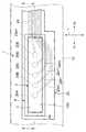
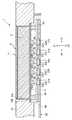
図1は本発明の押圧センサを操作面側から見たときの平面図、図2は図1の2−2線での切断断面図、図3ないし図5は動作説明図である。 FIG. 1 is a plan view of the pressure sensor of the present invention as viewed from the operation surface side, FIG. 2 is a cross-sectional view taken along line 2-2 of FIG. 1, and FIGS.
図1に示すように、押圧センサ1は、X方向に細長い帯状の弾性部材2を有している。また弾性部材2の裏面側にはメンブレンシート(基板シート)20が設けられ、前記メンブレンシート20にはX方向に沿って接点20A,20B,20C,20D,20Eが設けられている。各接点20A〜20Eは、等ピッチで形成されている。本実施の形態では、接点の間隔は10mm以下、具体的には4mmで形成されている。 As shown in FIG. 1, the
前記押圧センサ1は、小型の電子機器、例えばカメラ、携帯電話、オーディオ関連のリモコンなどに搭載することができる。前記押圧センサ1は、電子機器の筐体10に長方形の切欠き穴10aが形成されて、この切欠き穴10aから前記弾性部材2の表面の操作面3が露出している。 The
前記弾性部材2は、弾性変形可能な軟質な素材で形成され、また前記操作面3は、低摩擦抵抗の材料で形成されて前記弾性部材2の表面に重ねられている。このような低摩擦抵抗の操作面3が設けられていると、操作面3に対して指をX1−X2方向へ滑らかに移動させることができ、操作性を向上させることができる。ただし前記低摩擦抵抗の層は前記操作面3に設けられていなくてもよく、前記弾性部材2の表面がそのまま操作面3として機能していてもよい。 The
図2に示すように、前記弾性部材2のZ2側の面(裏面)には、補強部材4が重ねて形成されている。図1及び図2に示す実施形態では、前記弾性部材2、前記弾性部材2の表面に形成された低摩擦抵抗の層、及び前記弾性部材2の裏面に設けられた補強部材4の3層で所定厚みの複合シート11が構成されている。 As shown in FIG. 2, a reinforcing member 4 is formed on the Z2 side surface (back surface) of the
前記補強部材4は、図1に示すように、フィルム状に形成されたものであり、前記操作面3よりも側方に突出する形状である。前記操作面3よりも外側に突出する部分が本実施の形態での鍔部4aとなっている。この鍔部4aは、操作面3を取り囲むようにして全周に形成されている。 As shown in FIG. 1, the reinforcing member 4 is formed in a film shape, and has a shape protruding sideward from the operation surface 3. A portion protruding outward from the operation surface 3 is a
前記補強部材4のZ2側の面には、5個の半球状の突起5a,5b,5c,5d,5eが直線状に等間隔に設けられている。このとき、前記突起5a〜5eは、前記接点20A〜20Eの真上に位置にするように設けられている。なお前記突起は半球状である必要はない。さらに突起5aと5eの外側には支持部6a,6bが形成されている。これら突起5a〜5e及び支持部6a,6bは、いずれも紫外線硬化型の樹脂で形成され、印刷によって同時に形成されている。ただし、前記突起5a〜5e、支持部6a,6bは、必ずしも紫外線硬化樹脂である必要はない。前記紫外線硬化樹脂には、エポキシ系の樹脂の紫外線硬化促進剤が含有されたものを使用できる。 Five
なお、図示していないが、前記支持部6a,6bの表面には、粘着性を有する粘着層が形成されて、メンブレンシート20と接着固定されている。 In addition, although not shown in figure, the adhesive layer which has adhesiveness is formed in the surface of the said
図1と図2に示すように、前記メンブレンシート20は、上側シート21と下側シート22が対向して設けられ、前記上側シート21と下側シート22との間にシート状のスペーサ23が挿入されて、互いに接着固定されている。前記上側シート21と下側シート22は、いずれもPET樹脂やポリイミド樹脂など可撓性を有する素材で形成され、前記スペーサ23は接着層で形成されている。ただし、各シート21,22とスペーサ23のすべてがPET樹脂などで形成され、互いに接着固定されたものでもよい。 As shown in FIGS. 1 and 2, the
図2に示すように、前記上側シート21と下側シート22の対向面には、前記突起5aの対向位置に円形の導電部21a,22aが形成されている。また前記スペーサ23には、前記導電部21a,22aが露出する前記導電部21a,22aよりも大径の円形の貫通孔23aが形成されている。なお、前記と同様にして、前記突起5b,5c,5d,5eについても、導電部21b,21c,21d,21e、22b,22c,22d,22e及び貫通孔23b,23c,23d,23eが形成されている。互いに対向する一対の前記導電部によって、本実施の形態の接点が形成されている。 As shown in FIG. 2, circular
図1に示すように、前記メンブレンシート20では、前記下側シート22には、前記導電部22a〜22eから線状の電極部22a1,22b1,22c1,22d1,22e1と1本の共通電極部24がそれぞれX1方向へ互いに重ならないように延びて形成されている。共通電極部24は、下側シート22から上側シート21の各導電部21a〜21eまで延びて形成されている。また、前記電極部22a1〜22e1および共通電極部24が図示しない制御部まで延びて形成されている。 As shown in FIG. 1, in the
なお、前記導電部21a〜21e,22a〜22e、電極部22a1〜22e1および共通電極部24は、いずれも銅や銀などの金属材料で形成されている。 The
前記制御部では、前記共通電極部24に対して電流が与えられる。例えばこのとき導電部21cと22cとが互いに接触して前記電流が電極部22c1から出力されると、前記制御部では接点20Cが押圧操作されたと検知される。このようにして他の接点20A,20B,20D,20Eについても同様に検知される。 In the control unit, a current is applied to the
本実施の形態における弾性部材2は、シリコーンゴムで形成されていることが好ましい。以下においてその理由を説明する。 The
上記のような接点間隔の非常に狭い押圧センサ1では、接点1個当たり人の指で操作面3を触ったときに作用する力が例えば0.196N(ニュートン)である。よって、操作面3に0.196Nが作用したときに接点が入力状態に切り替えられることが好ましい。なお、メンブレンシート20に対して単体の接点を入力状態に切り替えるために必要な力は、例えば0.098〜0.147Nである。よって、弾性部材2としては、0.049〜0.098Nの低加重で撓み変形する素材が必要となる。そこで様々な素材について検討したところ、高密度ポリエチレンやポリプロピレンでは硬度が高く、低荷重で撓み変形できるものではなかった。特に高密度ポリエチレンなどは硬度における膜厚の依存性が高く、膜厚変化に対して硬度の大きさが大きく変動してしまう。 In the
また逆に低密度ポリエチレンでは高温での特性が悪く使用に耐え得るものではなかった。そこで最終的には、シリコーンゴムを使用したときに低荷重でしかも局部的に撓み変形させることができることが確認された。またシリコーンゴムは硬度における膜厚の依存性が、高密度ポリエチレンほど大きくなく使い勝手が良い。なお、この弾性部材2としては、シリコーンゴムに限定されるものではなく、その他のゴム系の部材であってもよい。 On the other hand, low density polyethylene has poor characteristics at high temperatures and cannot be used. Therefore, it was finally confirmed that when silicone rubber is used, it can be bent and deformed locally with a low load. Silicone rubber has a film thickness dependency on hardness that is not as great as high-density polyethylene and is easy to use. The
しかし前記弾性部材2単体であると、押圧力に対するZ方向への撓み変形が大きくなりすぎるため、適度な撓み変形とするため前記弾性部材2の裏面に補強部材4を設けている。前記補強部材4は、PET樹脂やポリプロピレン樹脂などで形成することができ、この補強部材4を弾性部材2の裏面に設けることで、Z方向へ所定量以上に撓むのを規制することが可能である。 However, if the
本発明では、上記のように例えばシリコーンゴムで形成された弾性部材2と前記弾性部材2が所定量以上に撓むのを規制する補強部材4とを有した複合シート11が使用されるが、このような構成の複合シート11を用いることで、押圧力による前記複合シート11の撓みの変形範囲を前記押圧力の大きさの変動に伴って連続的に変化させやすい。 In the present invention, as described above, the
図3に示すように、本実施の形態の押圧センサ1では、操作面3の表面に操作者が指Fを載せたときに、接点20B,20C,20Dを覆うことができる程度に前記接点間の間隔が規制されている。このとき、例えば接点20Cの真上をZ2方向へ押し下げると、まず指Fの腹の頂点F1から主に荷重M1が弾性部材2に加わり、前記弾性部材2が局部的に撓み変形させられる。このとき前記弾性部材2が撓み変形する範囲は、概ね前記指Fが前記弾性部材2上に接触した範囲である。そして、弾性部材2の変形に伴って補強部材4も撓み変形させられて、突起5cのみがZ2方向へ押し下げられる。上記したように、弾性部材2単体であると荷重M1が加えられたときに前記弾性部材2が撓みすぎ、特に指Fが前記弾性部材2上に接触した範囲よりも、さらに広い範囲に撓み変形が起こり、例えば突起5cのみならず突起5bや5dも下方に押し下げられる可能性がある。このためできる限り指Fで押した範囲内だけが撓むように前記弾性部材2の下に補強部材4を設け前記弾性部材2の撓みをある程度前記補強部材4が吸収する構成にする。 As shown in FIG. 3, in the
図3のように前記突起5cの下方への移動力によって、上側シート21が撓み変形させられて、上側シート21の導電部21cと下側シート22の導電部22cとが互いに接触して導通する。これにより、接点20Cが押圧操作されたことが検知される。 As shown in FIG. 3, the
上記したように、1個の入力点数を得るために必要な押圧力は例えば0.196Nであるから、図3は例えば押圧力を0.196Nとした場合である。 As described above, the pressing force necessary to obtain one input point is 0.196 N, for example, and FIG. 3 shows a case where the pressing force is 0.196 N, for example.
図4では、図3に示す状態から、さらに指FをZ2方向に押し前記弾性部材2への荷重M2が増すと、前記指Fの腹は、図3の状態よりも平たく潰れて前記弾性部材2への接触面積が増し、広い範囲にわたって前記弾性部材2の下方に押す。このため図4では、前記弾性部材2の撓み変形の範囲は図3の場合よりも広がる。この結果、図4の状態では、突起5bと5cの2つの突起が下方に移動し、この移動力によって前記上側シート21の導電部21bと21cと下側シート22の導電部22bと22cとが互いに接触して導通する。これにより、接点20Bと20Cが押圧操作されたことが検知される。 In FIG. 4, when the finger M is further pushed in the Z2 direction from the state shown in FIG. 3 and the load M2 applied to the
図5では、図4の状態から、さらに指FをZ2方向へ押し前記弾性部材2への荷重M3が増すと、前記指Fの腹は、図4の状態よりもさらに平たく潰れて前記弾性部材2への接触面積が増し、前記弾性部材2の撓み変形の範囲が図4の場合よりも広がる。この結果、図5の状態では、突起5b、5c、5dの3つの突起が下方に移動し、この移動力によって前記上側シート21の導電部21b、21c、21dと下側シート22の導電部22b、22c、22dとが互いに接触して導通する。これにより、接点20B、20C、20Dが押圧操作されたことが検知される。 In FIG. 5, when the finger M is further pushed in the Z2 direction from the state of FIG. 4 and the load M3 on the
このように前記弾性部材2は、押圧力(荷重)の大きさに合わせてその撓み変形範囲が変化し、押圧力を大きくしていくと、それに伴って前記弾性部材2の撓み変形範囲も徐々に大きくなり、図3の最も荷重が低い状態では接点数が1であるのに対し、図4の中間の荷重状態では接点数を2にでき、図5の最も荷重が大きい状態では前記接点数を3にできる。 As described above, the elastic deformation of the
この接点数の数は、前記導電部21a〜21e及び22a〜22e間、及び突起5a〜5e間の間隔を変えれば、当然に変わる。前記間隔を狭くすれば、押圧力を増すことで、前記入力点数を図5の状態の3よりも多くすることが可能である。例えば図3の軽荷重状態で前記入力点数を1〜2、図4の中間の荷重状態で前記入力点数を3〜4、図5の高荷重状態で前記入力点数を5以上に設定することができる。 The number of the contact points is naturally changed by changing the distance between the
いずれにしても本発明では、弾性部材2と補強部材3とで構成された複合シート11を用いれば、例えば図3の状態を低荷重の第1段階、図4の状態を中間の荷重の第2段階、図5の状態を高荷重の第3段階と規定したときに、各段階での前記入力点数を異なる数に高精度に規制することが可能になる。特に本発明では、上記第1段階での入力点数が1、第2段階での入力点数が2、第3段階での入力点数が3のように、各段階ごとの入力点数が規則的に変化することが好ましい。 In any case, in the present invention, when the
図3ないし図5の状態を維持することができれば、例えば突起5a〜5eを導電部材で形成し、メンブレンシート20を下側シート22と導電部22a〜22eのみで構成してもよい。かかる場合、突起と導電部との接触によって入力動作となる。 If the state of FIGS. 3 to 5 can be maintained, for example, the
しかし前記弾性部材2が図2の弾性部材2よりも、より軟質な材質でわずかな荷重を加えただけで、その撓み変形範囲が容易に広がってしまうような場合、図3と同様の荷重M1を加えただけで、図5のように弾性部材2が大きく撓み、3つの突起5b〜5dが上側シート21上に接触する可能性もある。逆に、より硬質の材質の場合、押された部分が撓まず、一気に多接点がONする可能性もある。かかる場合に突起5b〜5dを導電部材とし、例えばメンブレンシート20を下側シート22と導電部22a〜22eのみで構成してしまうと、ある荷重状態で既に入力点数が3つになり、前記荷重をそれ以上に増やしていっても、指Fの大きさに対向する部分に3つの突起5b〜5dしかない場合には、前記入力点数を増やすことができない。このため荷重を徐々に大きくしていっても前記入力点数を効果的に変化させる構成とすることができない。 However, when the
そのため本発明では、メンブレンシート20を少なくとも下側シート22と、前記下側シート22から所定距離離れた上側シート21と、前記上側シート21と下側シート22との対向面に形成された導電部21a〜21e,22a〜22eとを有して構成し、樹脂材の突起5a〜5eが前記上側シート21上を下側シート22側に押圧し、前記導電部21a〜21e,22a〜22e間が接触することで初めて入力動作となる構成により、徐々に大きくなる荷重に対して入力点数が増加する構成にできる。 Therefore, in the present invention, the
すなわち低い荷重M1で図5のように3つの突起5b,5c、5dが前記上側シート21上に接触してもこの状態では入力動作にはならない。この状態からさらに強い荷重が前記メンブレンシート20に加えられて導電部21a〜21e,22a〜22e間が接触して初めて入力動作になるが、メンブレンシート20を押す段階では、上側シート21上に接触した突起のうち真中の突起5cに最も強い荷重が加わっているはずで、前記突起5cにはその下方にある導電部21c,22c間を接触させるだけの荷重が与えらえられた状態であるのに対し、両脇の突起5b,5dには、前記突起5cほどの荷重が加わっておらず、その下方にある導電部21bと22b、21dと22d間を接触させるだけの荷重を有していない。よって低い荷重M1の状態で3つの突起が仮に上側シート21上に接触した状態でも、入力点数を1にでき、その状態から徐々に荷重を強めていけば、突起5b,5dにも導電部間を接触させるだけの強い荷重が加わり、入力点数を荷重の大きさに合わせて1→2→3と規則的に変化させやすい構成を得ることができる。 That is, even if the three
なお弾性部材2を撓ませて突起を上側シート21上にまで接触させるに必要な荷重よりも、メンブレンシート20にある導電部21a〜21e,22a〜22e間を接触させるために必要な荷重の方が大きいことが、荷重の大きさに合わせて、入力点数の変化をより高精度に規制できるため好ましい。 Note that the load necessary for bringing the
また、図1ないし図5はいずれも、非押圧状態では突起5a〜5eが上側シート21上に接触していないが、図1、図2の構造であれば、前記突起5a〜5eが前記上側シート21上に接触していても入力動作にはならないから、非押圧状態で既に前記突起5a〜5eが前記上側シート21上に接触した状態であってもよい。 1 to 5, the
また本実施の形態での補強部材4は、図1に示すように、操作面3の周縁部よりもX−Y平面方向へ延びる形成された鍔部4aを有している。このように鍔部4aが形成されていると、前記押圧センサ1を電子機器の筐体10に取り付ける際に筐体10の裏側から押圧センサ1が切欠き穴10aに挿入されると、前記鍔部4aが筐体10の内側に形成された段差状の係止部10bで係止されて、押圧センサ1が筐体10から抜け出るのが防止される。 Further, the reinforcing member 4 in the present embodiment has a
なお、前記押圧センサ1では、補強部材4が一枚のフィルム状のシートで形成されているが、これに限られるものではなく、弾性部材2の裏面に補強部材が固定され、さらに前記突起5a〜5eを設けた別のフィルム状の部材を前記補強部材に固定するようにしてもよい。このときの補強部材と別の部材は、PETなどの同じ樹脂を用いて形成することができる。 In the
図6は、第2の実施の形態の押圧センサを示す平面図である。この押圧センサ30は、操作面33が円形のリング状に形成されたものである。この押圧センサ30も前記押圧センサ1と基本的な構造は同じであり、シリコーンゴムで形成された弾性部材32と、補強部材34で形成されている。 FIG. 6 is a plan view showing a pressure sensor according to the second embodiment. The
前記押圧センサ30では、操作面33に沿って円周状に12個の接点31が設けられている。前記補強部材34は、操作面33の外周縁に沿って突出する環状の鍔部34aと、内周縁側に突出する環状の鍔部34bを有している。これにより、前記押圧センサ30が筐体に形成されたリング状の切欠き穴に筐体の裏側から挿入されたときに、前記鍔部34a,34bが前記筐体の内側で係止されて、前記押圧センサ30が筐体から抜け出るのが防止される。 In the
なお、前記押圧センサの操作面の形状としては、直線状や円形リング状のものに限らず、楕円形状であってもよく、十字形状であってもよい。 In addition, the shape of the operation surface of the press sensor is not limited to a linear shape or a circular ring shape, and may be an elliptical shape or a cross shape.
また、上記実施の形態では、透明系のシリコーンゴムとPET樹脂などを使用することで、操作面とは逆側から印刷や塗装することが可能となり、各色で外観を呈することができ、デザイン上の自由度も上げることが可能になる。 In the above embodiment, by using transparent silicone rubber and PET resin, it is possible to print and paint from the opposite side of the operation surface, and to have an appearance in each color, The degree of freedom can be increased.
図3ないし図5で説明したように本発明では、荷重の大きさに合わせて、入力点数が変化し、特に荷重の大きさの範囲を多段階に分けたときに、各段階に合わせて各段階での前記入力点数を異なる数に高精度に規制することが可能である。特に各段階に合わせて前記入力点数が規則的に変化する構成とすることができる。 As described with reference to FIGS. 3 to 5, in the present invention, the number of input points changes according to the magnitude of the load, and particularly when the range of the magnitude of the load is divided into multiple stages, It is possible to regulate the number of input points in a stage to a different number with high accuracy. In particular, the number of input points can be changed regularly according to each stage.
このため図1ないし図6に示す押圧センサは、例えばオーディオ機器のボリューム操作部として、あるいはチャンネル切替部等として機能させることができる。例えば指で徐々に強く押していきそれに伴って入力点数が増えていくと、ボリュームが上がり、逆に指での押圧力を弱めていくとボリュームが下がる等である。また前記弾性部材2の表面に前記弾性部材2よりも低摩擦抵抗の層を塗布し、前記複合シート11の操作面上を指でなぞったときに、チャンネルが切り替わるようにし、かかる場合に指で押す力を強めると、その切替スピードを変えることが可能な構成にでもできる。 For this reason, the press sensor shown in FIGS. 1 to 6 can function as, for example, a volume operation unit of an audio device or a channel switching unit. For example, if the finger is gradually strongly pressed and the number of input points is increased accordingly, the volume is increased, and conversely, if the finger is weakened, the volume is decreased. Further, when a layer having a lower friction resistance than that of the
本発明の押圧センサ1に設けられた制御部では、操作面3をX1−X2方向に軽い操作力で操作したときに選択項目の選択操作が可能になり、また操作面3を強い押圧力で操作したときに選択された選択項目の決定操作が可能になるように制御できる。以下、その構成について詳述する。 In the control unit provided in the
図7は押圧センサ1の回路ブロック図の一例を示すものである。
図7に示すように、機器本体に設けられた所定のバス40に、本発明の押圧センサ(本デバイス)1が所定のインターフェース1aを介して接続され、ディスプレイ41が表示制御部41aを介して接続されている。さらに前記バス40には、CPU42,ROM43,RAM44,タイマー45が接続されている。なお、本実施の形態での制御部は、CPU42,ROM43,RAM44,タイマー45などで構成されている。なお、押圧スイッチ1は、例えばデジタルスチルカメラ、デジタルビデオカメラ、携帯電話、PDA(パーソナルデジタルアシスタント)などの機器本体に搭載できる。FIG. 7 shows an example of a circuit block diagram of the
As shown in FIG. 7, the press sensor (present device) 1 of the present invention is connected to a
前記ディスプレイ41には、メニュー画面として複数の選択項目が上下方向や左右方向に表示可能であり、いずれかの選択項目を押圧センサ1の操作によって選択操作や選択決定操作できるように前記制御部で制御される。 On the
図8は、前記制御部での処理の流れを示すフローチャートである。なお、図8では、ステップを「ST」と略記して説明する。 FIG. 8 is a flowchart showing the flow of processing in the control unit. In FIG. 8, the step is abbreviated as “ST”.
まず、前記制御部において押圧スイッチ1の入力操作が監視されており、前記押圧スイッチ1が操作されたか否かが確認される(ST1)。操作されていない場合には(No)、処理を終了する。そして押圧スイッチ1が操作されるまでその操作を定期的に監視する。 First, an input operation of the
操作が検出された場合には(Yes)、ST2において動作に変化があったか否かが確認される。ST2において操作変化を検出すると、ST3において荷重変化の有無が確認される。ST3で荷重変化が検出された場合には(Yes)、ST5に移行して操作荷重が増加したかまたは減少したかが判断される。操作荷重が増加した場合には最大の荷重値を更新し(ST6)、この最大荷重値をRAM44に記憶する。 If an operation is detected (Yes), it is confirmed in ST2 whether or not the operation has changed. When an operation change is detected in ST2, the presence or absence of a load change is confirmed in ST3. If a load change is detected in ST3 (Yes), it is determined whether the operation load has increased or decreased in ST5. When the operation load increases, the maximum load value is updated (ST6), and this maximum load value is stored in the
またST5で操作荷重が減少したときにはST7に移行して、所定の最大荷重を超えているか否かが判断される。所定の最大荷重を超えた場合には(Yes)、選択決定操作(Enter操作)を出力し、そして最大荷重値をクリアする。また所定の最大荷重を超えなかった場合には(No)、ST1に戻る。なお、前記選択決定操作を出力する場合には、押圧スイッチ1の操作によって所定時間内に所定の変動幅を超えて検出された場合、例えば0.3秒の短時間内に4または5の接点(入力点)がONして最大荷重を超えてさらに操作荷重が減少した場合に選択決定操作と判断して、そのとき選択されていた選択項目を決定する。なお前記所定時間は前記タイマー45を動作させることにより計測する。 When the operation load decreases in ST5, the process proceeds to ST7 to determine whether or not the predetermined maximum load is exceeded. When the predetermined maximum load is exceeded (Yes), a selection determination operation (Enter operation) is output, and the maximum load value is cleared. If the predetermined maximum load is not exceeded (No), the process returns to ST1. In the case of outputting the selection determination operation, when the operation of the
ST4において、移動操作、例えば操作面3が所定の軽押圧力(1〜3個の接点がONしている状態)で摺動操作されたことが検出された場合には(Yes)、ST9に移行して移動操作の操作方向を検出する。例えば、図3乃至図5に示す押圧スイッチ1において、X1方向を上方向とし、X2方向を下方向としたときに、操作面3がX1方向に摺動操作されたときにはプラス(+)信号が出力され(ST10)、X2方向に摺動操作されたときにはマイナス(−)信号が出力される(ST11)。 In ST4, when it is detected that the moving operation, for example, the operation surface 3 is slid with a predetermined light pressing force (1 to 3 contacts are ON) (Yes), the process goes to ST9. The operation direction of the moving operation is detected by shifting. For example, in the
前記ST2において、操作に変化がない場合には(No)、前回検出された操作が移動出力である否かが判断される(ST12)。すなわち、操作面3が継続して押し下げ操作されている状態である。前回検出された操作はRAM44に記憶されており、今回検出された操作とがCPU42での演算処理により比較される。比較した結果、前回検出された操作による動作が移動出力であった場合には、前回と同じ移動データを出力する(ST13)。すなわち、同じ移動データであるため選択項目は移動することがなく、したがって選択項目の選択位置はそのままである。またST12において、前回検出された操作による動作が移動出力でない場合にはST1の処理に戻る。 In ST2, if there is no change in the operation (No), it is determined whether or not the operation detected last time is a movement output (ST12). That is, the operation surface 3 is continuously pressed down. The operation detected last time is stored in the
このように、押圧スイッチ1の操作面3を接点が1〜3個オンするような軽押圧力で移動させることにより移動信号が出力されて選択項目が上下左右に移動させられ、また押圧スイッチ1の操作面3をZ方向に接点が4または5個オンするような強押圧力で押し込み、所定の変動幅を超えたことが検出された場合には、選択決定操作に切り換えられてそのとき選択されている選択項目が選択決定と判断される。選択項目が決定されると、その選択項目に割り当てられているプログラムが作動して、例えば所定のアプリケーションが起動する。 As described above, by moving the operation surface 3 of the
なお、ST8においてEnter操作を出力する場合にそのEnter操作時に接点(入力点)の位置がずれて、操作者が選択したいと望んでいる選択項目とは異なる選択項目が選択決定されるおそれがある。この問題を解消するために、入力点数(ONしている接点の個数)が所定時間内に所定の変動幅を超えて検出された場合に、この入力点数が大幅に変動する前の位置で選択されている選択項目を選択決定の位置と判断する。変動前の位置は、タイマー45によって所定の時間(例えば0.5秒前など)を設定することができる。 When an Enter operation is output in ST8, the position of the contact (input point) may be shifted during the Enter operation, and a selection item different from the selection item that the operator desires to select may be selected. . In order to solve this problem, if the number of input points (number of contacts that are turned on) is detected within a predetermined fluctuation range within a predetermined time, select the position before this input point fluctuates significantly. The selected item is determined as the selection decision position. The position before the change can be set for a predetermined time (for example, 0.5 seconds before) by the
またその他の手段としては、例えば15個の接点を一列に配列して、これを3つの領域に区分して、各領域に5個の接点を配置する。この構成では、ONの接点数が多い領域が選択決定されたと判断する。このように、多くの接点を配置することで、選択決定操作時のずれによる誤操作を吸収することができる。 As another means, for example, 15 contacts are arranged in a line, and this is divided into three regions, and five contacts are arranged in each region. In this configuration, it is determined that a region having a large number of ON contacts has been selected and determined. In this way, by arranging many contact points, it is possible to absorb an erroneous operation due to a shift during the selection determination operation.
このように設定することで、選択項目の決定操作まで同じ位置を保持する必要がなくなり、操作性を損なうことなく滑らかな入力操作が可能になる。 By setting in this way, it is not necessary to hold the same position until the selection item determination operation, and a smooth input operation is possible without impairing operability.
なお、図6に示す押圧スイッチ30についても同様に制御することで、選択項目の選択操作と選択決定操作とを入力可能である。 Note that the selection switch selection operation and the selection determination operation can be input by similarly controlling the
1 押圧センサ
2 弾性部材
3 操作面
4 補強部材
4a 鍔部
5a〜5e 突起
6a,6b 支持部
10 筐体
10a 切欠き穴
10b 係止部
11 複合シート
20A〜20E 接点
20 メンブレンシート
21 上側シート
22 下側シート
23 スペーサDESCRIPTION OF
Claims (12)
Translated fromJapanese前記複合シートの補強部材には、前記各接点に個別に対向してそれぞれが前記接点に向けて突出する複数の突起が設けられ、
前記弾性体の表面が押圧されて変形すると、前記補強部材が前記基板シートに向けて撓み変形させられて、前記突起で前記接点が押圧されて前記接点が入力状態に切り替えられるものであり、
前記補強部材が前記基板シートに向けて撓んだときに、その撓み量の大きさによって、前記補強部材に設けられた1個の前記突起で1個の前記接点のみが入力状態に切り替えられ、あるいは前記補強部材に設けられた複数の前記突起で複数の前記接点が入力状態に切り替えられることを特徴とする押圧センサ。An elastic bodyformed of a rubber material, a composite sheet having a predetermined thickness is provided on the backside have a reinforcing memberof a resin sheet for regulating wrinklesMiof the elastic body of the elastic body, wherein comprises a substrate sheetwas found provided apart reinforcing membera predetermined distance of the composite sheet,and a plurality of contacts switched to the input state by the pressing operation provided on the substrate sheet, and
The reinforcing memberof the composite sheet isprovided witha plurality of protrusions thatindividually faceeach of the contacts andprotrude toward thecontacts ,
When the surface of theelastic bodyyou deformed by being pressed,said reinforcingmember being resiliently deformed towardthe substrate sheet, the projections said contacts are pressed bythose Erareru switch to the contact input statusYes,
When the reinforcing member bends toward the substrate sheet, depending on the amount of bending, only one of the contacts is switched to the input state by one protrusion provided on the reinforcing member, Alternatively, the plurality of contacts are switched to the input state by the plurality of protrusions provided on the reinforcing member .
Priority Applications (1)
| Application Number | Priority Date | Filing Date | Title |
|---|---|---|---|
| JP2004006421AJP4028491B2 (en) | 2003-07-03 | 2004-01-14 | Press sensor |
Applications Claiming Priority (2)
| Application Number | Priority Date | Filing Date | Title |
|---|---|---|---|
| JP2003190760 | 2003-07-03 | ||
| JP2004006421AJP4028491B2 (en) | 2003-07-03 | 2004-01-14 | Press sensor |
Publications (2)
| Publication Number | Publication Date |
|---|---|
| JP2005038812A JP2005038812A (en) | 2005-02-10 |
| JP4028491B2true JP4028491B2 (en) | 2007-12-26 |
Family
ID=34220594
Family Applications (1)
| Application Number | Title | Priority Date | Filing Date |
|---|---|---|---|
| JP2004006421AExpired - Fee RelatedJP4028491B2 (en) | 2003-07-03 | 2004-01-14 | Press sensor |
Country Status (1)
| Country | Link |
|---|---|
| JP (1) | JP4028491B2 (en) |
Families Citing this family (5)
| Publication number | Priority date | Publication date | Assignee | Title |
|---|---|---|---|---|
| JP2006345209A (en) | 2005-06-08 | 2006-12-21 | Sony Corp | Input device, information processing apparatus, information processing method, and program |
| JP2008305174A (en) | 2007-06-07 | 2008-12-18 | Sony Corp | Information processor, information processing method, and program |
| KR101168710B1 (en) | 2011-02-24 | 2012-07-30 | 주식회사 마블덱스 | A method to calibrate key button with membrane pressure sensor |
| CN102620866A (en)* | 2012-03-30 | 2012-08-01 | 山东昌润科技有限公司 | Digital-type temperature pressure oil-filled core |
| CN111049510B (en)* | 2019-12-25 | 2023-10-27 | 维沃移动通信有限公司 | Touch key, control method and electronic equipment |
- 2004
- 2004-01-14JPJP2004006421Apatent/JP4028491B2/ennot_activeExpired - Fee Related
Also Published As
| Publication number | Publication date |
|---|---|
| JP2005038812A (en) | 2005-02-10 |
Similar Documents
| Publication | Publication Date | Title |
|---|---|---|
| KR100791378B1 (en) | User command input device supporting various input modes and equipment using the same | |
| CN101449230B (en) | input device | |
| US6704005B2 (en) | Input device which allows button input operation and coordinate input operation to be performed in the same operation plane | |
| US7310088B2 (en) | Input operation device | |
| US20080316180A1 (en) | Touch Screen Keyboard With Tactile Feedback, and Associated Method | |
| US20100321330A1 (en) | Touch panel and electronic device including the same | |
| US20120068934A1 (en) | Interactive keyboard with viewable display | |
| US20110248921A1 (en) | Keycap construction for keyboard with display functionality | |
| US20110079450A1 (en) | Small Device | |
| US7176899B2 (en) | Display screen operation device | |
| JP2013156095A (en) | Sensor device, input device and electronic apparatus | |
| JP4028491B2 (en) | Press sensor | |
| JP4005833B2 (en) | Display screen operation device | |
| JP4288205B2 (en) | Coordinate input device | |
| US7936335B2 (en) | Operation direction judging method for operation key in direction detecting switch | |
| US20060278512A1 (en) | Electronic device | |
| JP2004192413A (en) | Input device, mobile information processor, remote control device, and piezoelectric actuator driving control method for input device | |
| JP2008146679A (en) | Input device and electronic device equipped therewith | |
| JP2006134609A (en) | Operation device | |
| US20060060459A1 (en) | Operation device | |
| JP4278555B2 (en) | Touch input device | |
| JP4336535B2 (en) | Operating device | |
| JP4301884B2 (en) | Push-type operating device | |
| JP2005063936A (en) | Operation device | |
| JP4276584B2 (en) | Operating device |
Legal Events
| Date | Code | Title | Description |
|---|---|---|---|
| A131 | Notification of reasons for refusal | Free format text:JAPANESE INTERMEDIATE CODE: A131 Effective date:20070529 | |
| A521 | Written amendment | Free format text:JAPANESE INTERMEDIATE CODE: A523 Effective date:20070725 | |
| TRDD | Decision of grant or rejection written | ||
| A01 | Written decision to grant a patent or to grant a registration (utility model) | Free format text:JAPANESE INTERMEDIATE CODE: A01 Effective date:20071002 | |
| A61 | First payment of annual fees (during grant procedure) | Free format text:JAPANESE INTERMEDIATE CODE: A61 Effective date:20071011 | |
| FPAY | Renewal fee payment (event date is renewal date of database) | Free format text:PAYMENT UNTIL: 20101019 Year of fee payment:3 | |
| R150 | Certificate of patent or registration of utility model | Free format text:JAPANESE INTERMEDIATE CODE: R150 | |
| FPAY | Renewal fee payment (event date is renewal date of database) | Free format text:PAYMENT UNTIL: 20111019 Year of fee payment:4 | |
| FPAY | Renewal fee payment (event date is renewal date of database) | Free format text:PAYMENT UNTIL: 20111019 Year of fee payment:4 | |
| FPAY | Renewal fee payment (event date is renewal date of database) | Free format text:PAYMENT UNTIL: 20121019 Year of fee payment:5 | |
| FPAY | Renewal fee payment (event date is renewal date of database) | Free format text:PAYMENT UNTIL: 20131019 Year of fee payment:6 | |
| LAPS | Cancellation because of no payment of annual fees |