JP4025646B2 - High pressure low capacity pump - Google Patents
High pressure low capacity pumpDownload PDFInfo
- Publication number
- JP4025646B2 JP4025646B2JP2002549862AJP2002549862AJP4025646B2JP 4025646 B2JP4025646 B2JP 4025646B2JP 2002549862 AJP2002549862 AJP 2002549862AJP 2002549862 AJP2002549862 AJP 2002549862AJP 4025646 B2JP4025646 B2JP 4025646B2
- Authority
- JP
- Japan
- Prior art keywords
- piston
- pump
- ball
- socket
- drive
- Prior art date
- Legal status (The legal status is an assumption and is not a legal conclusion. Google has not performed a legal analysis and makes no representation as to the accuracy of the status listed.)
- Expired - Fee Related
Links
- 239000000463materialSubstances0.000claimsabstractdescription13
- 125000006850spacer groupChemical group0.000claimsdescription7
- XEEYBQQBJWHFJM-UHFFFAOYSA-NIronChemical compound[Fe]XEEYBQQBJWHFJM-UHFFFAOYSA-N0.000claimsdescription6
- 229910052742ironInorganic materials0.000claimsdescription3
- 239000012530fluidSubstances0.000abstractdescription6
- 229910052594sapphireInorganic materials0.000abstractdescription4
- 239000010980sapphireSubstances0.000abstractdescription4
- 229910052845zirconInorganic materials0.000abstractdescription4
- GFQYVLUOOAAOGM-UHFFFAOYSA-Nzirconium(iv) silicateChemical compound[Zr+4].[O-][Si]([O-])([O-])[O-]GFQYVLUOOAAOGM-UHFFFAOYSA-N0.000abstractdescription4
- 230000014759maintenance of locationEffects0.000abstractdescription2
- 238000004128high performance liquid chromatographyMethods0.000description7
- 239000007788liquidSubstances0.000description7
- 230000033001locomotionEffects0.000description7
- KFZMGEQAYNKOFK-UHFFFAOYSA-NIsopropanolChemical compoundCC(C)OKFZMGEQAYNKOFK-UHFFFAOYSA-N0.000description6
- OKKJLVBELUTLKV-UHFFFAOYSA-NMethanolChemical compoundOCOKKJLVBELUTLKV-UHFFFAOYSA-N0.000description6
- 230000005540biological transmissionEffects0.000description4
- 239000002904solventSubstances0.000description4
- WEVYAHXRMPXWCK-UHFFFAOYSA-NAcetonitrileChemical compoundCC#NWEVYAHXRMPXWCK-UHFFFAOYSA-N0.000description3
- 230000008901benefitEffects0.000description3
- 230000008878couplingEffects0.000description3
- 238000010168coupling processMethods0.000description3
- 238000005859coupling reactionMethods0.000description3
- 230000004907fluxEffects0.000description2
- 229910052761rare earth metalInorganic materials0.000description2
- 238000004587chromatography analysisMethods0.000description1
- 238000004891communicationMethods0.000description1
- 239000002178crystalline materialSubstances0.000description1
- 229910052500inorganic mineralInorganic materials0.000description1
- 238000003780insertionMethods0.000description1
- 230000037431insertionEffects0.000description1
- 239000000696magnetic materialSubstances0.000description1
- 238000000034methodMethods0.000description1
- 239000011707mineralSubstances0.000description1
- 238000005086pumpingMethods0.000description1
- 229910001404rare earth metal oxideInorganic materials0.000description1
- 150000002910rare earth metalsChemical class0.000description1
- 230000035939shockEffects0.000description1
Images
Classifications
- F—MECHANICAL ENGINEERING; LIGHTING; HEATING; WEAPONS; BLASTING
- F04—POSITIVE - DISPLACEMENT MACHINES FOR LIQUIDS; PUMPS FOR LIQUIDS OR ELASTIC FLUIDS
- F04B—POSITIVE-DISPLACEMENT MACHINES FOR LIQUIDS; PUMPS
- F04B53/00—Component parts, details or accessories not provided for in, or of interest apart from, groups F04B1/00 - F04B23/00 or F04B39/00 - F04B47/00
- F04B53/14—Pistons, piston-rods or piston-rod connections
- F—MECHANICAL ENGINEERING; LIGHTING; HEATING; WEAPONS; BLASTING
- F04—POSITIVE - DISPLACEMENT MACHINES FOR LIQUIDS; PUMPS FOR LIQUIDS OR ELASTIC FLUIDS
- F04B—POSITIVE-DISPLACEMENT MACHINES FOR LIQUIDS; PUMPS
- F04B53/00—Component parts, details or accessories not provided for in, or of interest apart from, groups F04B1/00 - F04B23/00 or F04B39/00 - F04B47/00
- F04B53/22—Arrangements for enabling ready assembly or disassembly
- F—MECHANICAL ENGINEERING; LIGHTING; HEATING; WEAPONS; BLASTING
- F04—POSITIVE - DISPLACEMENT MACHINES FOR LIQUIDS; PUMPS FOR LIQUIDS OR ELASTIC FLUIDS
- F04B—POSITIVE-DISPLACEMENT MACHINES FOR LIQUIDS; PUMPS
- F04B53/00—Component parts, details or accessories not provided for in, or of interest apart from, groups F04B1/00 - F04B23/00 or F04B39/00 - F04B47/00
- F04B53/14—Pistons, piston-rods or piston-rod connections
- F04B53/144—Adaptation of piston-rods
- F04B53/147—Mounting or detaching of piston rod
- B—PERFORMING OPERATIONS; TRANSPORTING
- B82—NANOTECHNOLOGY
- B82Y—SPECIFIC USES OR APPLICATIONS OF NANOSTRUCTURES; MEASUREMENT OR ANALYSIS OF NANOSTRUCTURES; MANUFACTURE OR TREATMENT OF NANOSTRUCTURES
- B82Y40/00—Manufacture or treatment of nanostructures
- F—MECHANICAL ENGINEERING; LIGHTING; HEATING; WEAPONS; BLASTING
- F05—INDEXING SCHEMES RELATING TO ENGINES OR PUMPS IN VARIOUS SUBCLASSES OF CLASSES F01-F04
- F05C—INDEXING SCHEME RELATING TO MATERIALS, MATERIAL PROPERTIES OR MATERIAL CHARACTERISTICS FOR MACHINES, ENGINES OR PUMPS OTHER THAN NON-POSITIVE-DISPLACEMENT MACHINES OR ENGINES
- F05C2203/00—Non-metallic inorganic materials
- F05C2203/08—Ceramics; Oxides
- F05C2203/0804—Non-oxide ceramics
- F05C2203/083—Nitrides
- F05C2203/0852—Nitrides of zirconium
- F—MECHANICAL ENGINEERING; LIGHTING; HEATING; WEAPONS; BLASTING
- F05—INDEXING SCHEMES RELATING TO ENGINES OR PUMPS IN VARIOUS SUBCLASSES OF CLASSES F01-F04
- F05C—INDEXING SCHEME RELATING TO MATERIALS, MATERIAL PROPERTIES OR MATERIAL CHARACTERISTICS FOR MACHINES, ENGINES OR PUMPS OTHER THAN NON-POSITIVE-DISPLACEMENT MACHINES OR ENGINES
- F05C2203/00—Non-metallic inorganic materials
- F05C2203/08—Ceramics; Oxides
- F05C2203/0865—Oxide ceramics
- F05C2203/0869—Aluminium oxide
- F05C2203/0873—Sapphire
Landscapes
- Engineering & Computer Science (AREA)
- Mechanical Engineering (AREA)
- General Engineering & Computer Science (AREA)
- Reciprocating Pumps (AREA)
- Details Of Reciprocating Pumps (AREA)
- Feeding And Controlling Fuel (AREA)
- Pistons, Piston Rings, And Cylinders (AREA)
- Non-Positive Displacement Air Blowers (AREA)
- Applications Or Details Of Rotary Compressors (AREA)
Abstract
Description
Translated fromJapanese【0001】
〔発明の分野〕
本発明は、高圧液体クロマトグラフィに適した、改良された高圧低容量ポンプに関する。
【0002】
〔従来技術の説明〕
厳密に測定された微小容量の液体を非常な高圧で正確に送出するポンプの要望がある。例えば、高圧液体クロマトグラフィ(HPLC)法を行う際、典型的には、メタノール又はイソプロピルアルコール等の液体溶剤を送出するモーター駆動ポンプが使用される。クロマトグラフィカラムの移動相のための溶剤を、より少ない量使用し、それをより高圧で作動させる傾向がある。例えば、数百バールの圧力で1分間当たり約50ナノリットル乃至約250マイクロリットルの範囲の低流量の流体を送出することができるポンプを提供することが望ましい。
【0003】
かかる低流量容量のために設計されたピストンポンプは、このピストンポンプの液体取扱い構成要素の寸法を非常に小さくしなければならないので、必然的に精密になる。サファイヤ又はジルコン等の材料は、精密な寸法公差及び表面公差を非常に小さい寸法で提供することができるので、サファイヤ又はジルコン等で作られた小直径ピストンの使用により、低容量HPLCポンプは利益を得る。しかしながら、これらの材料は脆弱であり且つ容易に破損するので、問題が存在する。高圧低容量ポンプの組立て及び作動中、小さくて精密なピストンの破損を回避することは困難である。
【0004】
〔発明の概要〕
本発明の主目的は、数百バールの高圧で1分間当たりナノリットルのレンジの正確に測定された液体流量を供給することが可能な、改良された高圧低容量ポンプを提供することにある。更に、本発明の目的は、ポンプの組立て及び作動中におけるピストンの破損の問題を解決すると共に、脆弱な材料で作られた微小ピストンを採用することができるポンプを提供すること、スプリングのような機械式ピストン保持の必要を回避するポンプを提供すること、ピストンとピストン駆動装置との厳密且つ高価な心出し作業の必要がないポンプを提供すること、及び、過去に使用されてきたポンプの不利益を解消する高圧低容量ポンプを提供することにある。
【0005】
本発明によれば、概略的には、高圧液体クロマトグラフィ等のための高圧低容量ポンプが提供される。ポンプは、ポンプセクションを含み、このポンプセクションは、ポンプシリンダーと、ポンピングされた流体がポンプシリンダに流入するための通路とそれから流出するための通路とを含む。ピストン組立体は、シリンダーの中を往復動可能なピストンと、第1端でこのピストンを支持するピストンホルダーとを含む。モーターの作動に応答してピストン組立体を往復動させるために、ピストン駆動装置がモーターとピストンホルダーの第2端との間に連結される。ピストンは、約10ミリメートルよりも小さい直径を有する細くて長いロッドである。ピストン駆動装置とピストンホルダーの第2端との相互連結部は、ソケットの中に枢動可能に受入れられる球形部材を有するボール−ソケットカップリングを含む。ソケット内の磁石が、磁力を使用して、球形部材をソケットの中に保持する。
【0006】
本発明は、上述及びその他の目的及び利点と共に、図面に示した本発明の好ましい実施形態の以下の詳細な説明から良く理解されよう。
【0007】
〔好ましい実施形態の詳細な説明〕
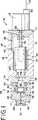
図1を参照すれば、本発明の原理に従って構成され、全体的に10として指示される高圧低容量ポンプが図示されている。ポンプ10は、高圧液体クロマトグラフィ法の溶剤液体移動相を提供するのに有用であり、メタノール、イソプロピルアルコール、アセトニトリル等の溶剤を、少なくとも6百バールの圧力で1分間当たり約50ナノリットル乃至約250マイクロリットルの範囲の低流量でポンピングすることが可能である。
【0008】
これらの望ましい性能特性を達成するために、ポンプ10は、約10ミリメートルよりも小さい直径、好ましくは、約1乃至約3ミリメートルの範囲の直径を有する細くて長いロッドの形態のピストン12を含んでいる。ピストン12は、結晶性材料、好ましくは、サファイヤで、又は、鉱物のような同様の特性を有する材料、好ましくは、ジルコンで作られるのが良い。かかる材料の利点は、厳密な公差と表面特性を有するこれらの材料を、本発明に必要な非常に小さい寸法で提供することができることにある。この材料及び寸法で作られたピストン12の潜在的な不利益は、ピストン12が脆弱であり、ポンプを組立てて作動させるとき、ピストン12が破損し易いことにある。本発明は、この潜在的な不利益を乗り越え、ポンプピストン12の破損の問題を解決する。
【0009】
ポンプ10の更に詳細な説明を続けると、ポンプ10は、端キャップ16を支持するポンプ本体14を含み、端キャップ16には、駆動モーター18が固着されている。駆動モーター18は、マイクロプロセッサの制御の下で正確に回転させることができるステッピングモーターであり、マイクロプロセッサは、駆動モーター18の後部のエンコーダからの信号を受信する検出器22からケーブル20を通して提供される位置フィードバック信号を受信する。
【0010】
ピストン12を含むピストン組立体24は、駆動伝達装置28によって駆動モーター18に連結されているピストン駆動装置26によって直線的に往復動され、駆動伝達装置28は、モーター18の回転運動をピストン駆動装置26及びピストン組立体24の直線運動に変換する。ピストン12は、ピストンハウジング36に取付けたポンプヘッド34に機械加工されたポンプセクション32の一部分であるポンプシリンダ30内を往復動し、ピストンハウジング36は、ポンプ本体14に固着されたキャップ38と、キャップ38とポンプヘッド34との間に配置されたスペーサ40とを含んでいる。
【0011】
ポンプヘッド34のポンプセクション32は、流入通路42と、流出通路44とを含み、両者は、ポンプシリンダ30と連通している。ピストン12の周りには、流体がピストン12の表面に沿ってポンプシリンダ30の中に流れるのに十分な隙間があり、流入通路42及び流出通路44は、所望ならば、ポンプシリンダの長さ方向に沿ったその他の箇所、例えば、流入バルブ及び流出バルブをポンプヘッド34の内部に又はその上に直接取付けることが可能な箇所に配置されていても良い。ポンプヘッド34のところに又はそこから遠くに配置された流入バルブ(図示せず)は、ピストン12がポンプシリンダ30から外方に(図1に示す右方に)移動されたとき、流体を流入通路42及びポンプシリンダ30に流入させるように開口する。ポンプヘッド34のところに又はそこから遠くに配置された流出バルブ(図示せず)は、ピストン12がポンプシリンダ30の内方に(図1に示す左方に)移動されたとき開口する。流入バルブ及び流出バルブは、チェックバルブ、又は、ソレノイドバルブのようなマイクロプロセッサー制御バルブであるのが良い。HPLC装置内の移動相連続流を提供するために、複数のバルブ10の組立体が、少なくとも1つのバルブ10が常に流出する流れを提供するように使用される。
【0012】
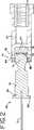
ピストン組立体24は、ピストンホルダー46を含み、このピストンホルダー46は、その一端に、ピストン12が挿入され且つ固着された、軸線方向に延びる細くて長い孔を有する。ピストンホルダー46は、スペーサ本体40の中のリンスチャンバー48内で往復動する。リンスポート50の中を流れるリンス液体は、リンスチャンバー48の中を通って流れる。ポンピングされた流体は、折畳み可能なベローズシール52によってリンス液体から隔絶され、ベローズシール52は、ピストンホルダー46の溝54内にある一端と、キャップ38とスペーサ本体40との間に捕捉された他端とを有している。図1に示している、ピストン12が完全に延びた位置は、ピストンホルダー46の係止フランジ56がポンプヘッド34にぶつかって係合することによって定められる。
【0013】
駆動伝達装置26は、シャフトカップリング62によって駆動モーター18の駆動シャフト60と軸線方向に整列し且つそれに固着されているねじスクリュー58を有する。駆動伝達装置26は、駆動ねじスクリュー58を軸線方向に受入れる中空の駆動カラー64を含んでいる。駆動カラー64の半径方向に延びる突出部66が、駆動カラー64の回転を防止するために、ポンプ本体14の軸線方向に延びるスロット68に受入れられている。駆動ねじ用ナット70が駆動カラー64の中に取付けられ、駆動ねじスクリュー58と噛合っている。ベアリング72が駆動カラー64を、駆動カラー64がポンプ10の軸線に沿う直線運動をすることができるように支持している。駆動モーター18が駆動シャフト60を回転させるとき、駆動ねじスクリュー58の回転により、それに噛合っている駆動ねじ用ナット70及び駆動カラー64の直線運動が厳密に制御されることになる。
【0014】
本発明によれば、ボールソケット連結部74が駆動カラー64とピストンホルダー46との間の駆動力を伝達する。ピストン12と反対側のピストンホルダー46の端部は、カップリングボール76を構成するために球形である。駆動カラー64の端部は、ボール76を受入れるソケット78を備えている。ボールソケット連結部74を使用することにより、ピストン駆動装置26の軸線とピストン組立体24の運動軸線とを正確に心出しする必要を回避する。厳密な公差のコストが省略され、心ずれによるピストン12の破損が防止される。
【0015】
ボール76をソケット78の中に維持し、ピストン駆動装置26がピストン組立体を押すことと引くことの両方を可能にするために、磁石80がソケット78に組込まれる。ボール78は、スプリングまたはその他の保持装置によって機械的に保持されるのではなく、磁力によって保持される。ソケット78は、ほぼカップ形状であり、マグネット80を保持するためのネスト又は凹所を構成するベース壁82と、ボールを包囲する側壁84とを有する。ボール76を含んでいるピストンホルダー46は、磁石80によって引き付けられる磁気材料、好ましくは、鉄材料で形成される。好ましくはプラスチックからなる、非磁気スペーサ86が、ボール76を磁石80の表面のところに且つ磁石80にきわめて近接して配置し、ソケット78内でのボール76の枢動自在運動を可能にする。磁石80は、レアアース(希土類元素又はその酸化物)、ネオジム−鉄−バロン磁石であるのが好ましいが、その他の材料であっても良い。
【0016】
磁気保持力は、側壁84の中に支持され且つボール76の中央平面を包囲する、軟鉄のような低磁気抵抗材料のリング88によって最大にされる。リング88は、磁石80とボール76を含む低磁気抵抗経路に寄与し、開放端磁束経路をより多くの閉磁束経路を変えることによって、磁気保持力を増大させる。
【0017】
ポンプ10を組立てる際、キャップ38をポンプ本体14に接合すると、ボール76がソケット78に入り込み、マグネット80によってボール76を図1に示す完全に着座した位置に推す。これは、ピストン12に衝撃又は応力を付与しない緩やかで滑らかな運動であり、かくして、破損を回避する。もし機械的な保持装置が使用されていれば、ソケット78へのピストン12の挿入は、ピストンホルダー46に付与される突然の運動又は非軸線方向力に起因した衝撃又は応力による損傷を引き起こす傾向がある。
【0018】
図面に示した本発明の実施形態の詳細を参照して本発明を説明したけれども、これらの詳細は、請求の範囲に記載された本発明の範囲を限定するものではない。
【図面の簡単な説明】
【図1】 本発明に従って構成された高圧低容量ポンプの主軸における断面図である。
【図2】 図1の高圧低容量ポンプのピストン組立体及びピストン駆動装置の拡大断面図である。[0001]
(Field of the Invention)
The present invention relates to an improved high pressure low volume pump suitable for high pressure liquid chromatography.
[0002]
[Description of prior art]
There is a need for a pump that accurately delivers precisely measured minute volumes of liquid at very high pressures. For example, when performing a high pressure liquid chromatography (HPLC) method, a motor driven pump that typically delivers a liquid solvent such as methanol or isopropyl alcohol is used. There is a tendency to use smaller amounts of solvent for the mobile phase of the chromatography column and to operate it at higher pressures. For example, it would be desirable to provide a pump capable of delivering a low flow rate fluid in the range of about 50 nanoliters to about 250 microliters per minute at a pressure of several hundred bar.
[0003]
Piston pumps designed for such a low flow capacity are necessarily precise because the dimensions of the liquid handling components of the piston pump must be very small. Since materials such as sapphire or zircon can provide precise dimensional tolerances and surface tolerances with very small dimensions, the use of small diameter pistons made of sapphire or zircon etc. makes low volume HPLC pumps profitable. obtain. However, problems exist because these materials are fragile and easily break. During assembly and operation of a high pressure low capacity pump, it is difficult to avoid small and precise piston breakage.
[0004]
[Summary of the Invention]
The main object of the present invention is to provide an improved high pressure low volume pump capable of supplying a precisely measured liquid flow rate in the nanoliter range per minute at high pressures of several hundred bar. It is a further object of the present invention to provide a pump that can solve the problem of piston breakage during pump assembly and operation, and that can employ micropistons made of fragile materials, such as springs. Providing a pump that avoids the need for mechanical piston retention, providing a pump that does not require a rigorous and expensive centering operation between the piston and piston drive, and the disadvantages of pumps that have been used in the past. The object is to provide a high-pressure, low-volume pump that eliminates the benefits.
[0005]
The present invention generally provides a high-pressure low-volume pump for high-pressure liquid chromatography and the like. The pump includes a pump section that includes a pump cylinder and a passage for pumped fluid to flow into and out of the pump cylinder. The piston assembly includes a piston that can reciprocate in a cylinder and a piston holder that supports the piston at a first end. A piston drive is coupled between the motor and the second end of the piston holder for reciprocating the piston assembly in response to operation of the motor. The piston is a thin and long rod with a diameter of less than about 10 millimeters. The interconnection between the piston drive and the second end of the piston holder includes a ball-socket coupling having a spherical member that is pivotally received within the socket. A magnet in the socket uses magnetic force to hold the spherical member in the socket.
[0006]
The invention, together with the foregoing and other objects and advantages, will be better understood from the following detailed description of the preferred embodiments of the invention illustrated in the drawings.
[0007]
Detailed Description of Preferred Embodiments
Referring to FIG. 1, there is illustrated a high pressure low capacity pump constructed in accordance with the principles of the present invention and generally designated as 10. The
[0008]
In order to achieve these desirable performance characteristics, the
[0009]
Continuing with a more detailed description of the
[0010]
The
[0011]
The
[0012]
The
[0013]
The
[0014]
According to the present invention, the ball
[0015]
A
[0016]
The magnetic holding force is maximized by a
[0017]
When assembling the
[0018]
Although the invention has been described with reference to details of embodiments of the invention shown in the drawings, these details do not limit the scope of the invention described in the claims.
[Brief description of the drawings]
FIG. 1 is a cross-sectional view of a main shaft of a high-pressure low-volume pump constructed according to the present invention.
2 is an enlarged cross-sectional view of a piston assembly and a piston driving device of the high-pressure low-capacity pump shown in FIG.
Claims (7)
Translated fromJapanese(B)ピストンホルダーと、を有し、
前記ピストンホルダーは、第1端と、その第1端と反対側に配置された第2端と、を有し、前記ピストンホルダーの第1端に、前記ピストンが取り付けられ、前記ピストンホルダーの第2端に、ボールが配置され、
(C)さらに、ピストン駆動装置の一端に設けられたソケットを有し、
前記ソケットは、
(1)ベース壁と、
(2)前記ベース壁から軸線方向に延び、前記ボールの少なくとも一部分を取り囲む側壁と、
(3)前記ベース壁内に保持され、前記ボールを前記ソケットの中に磁力を使って保持する磁石と、を有し、
前記ボールと前記磁石との間に配置されたスペーサを更に有する、高圧低容量ポンプ。(A) a piston;
(B) a piston holder,
The piston holder has a first end and a second end disposed opposite to the first end. The piston is attached to the first end of the piston holder, and the piston holder has a first end. A ball is placed at the two ends,
(C) Furthermore, it has a socket provided at one end of the piston drive device,
The socket is
(1) a base wall;
(2) a side wall extending in an axial direction from the base wall and surrounding at least a part of the ball;
(3) a magnet that is held in the base wall and holds the ball in the socket using magnetic force,
A high-pressure and low-capacity pump further comprising a spacer disposed between the ball and the magnet.
Applications Claiming Priority (2)
| Application Number | Priority Date | Filing Date | Title |
|---|---|---|---|
| EP00403469AEP1213479B1 (en) | 2000-12-11 | 2000-12-11 | High pressure low volume pump |
| PCT/US2001/044927WO2002048582A1 (en) | 2000-12-11 | 2001-11-30 | High pressure low volume pump |
Publications (3)
| Publication Number | Publication Date |
|---|---|
| JP2004515697A JP2004515697A (en) | 2004-05-27 |
| JP2004515697A5 JP2004515697A5 (en) | 2005-12-22 |
| JP4025646B2true JP4025646B2 (en) | 2007-12-26 |
Family
ID=8173978
Family Applications (1)
| Application Number | Title | Priority Date | Filing Date |
|---|---|---|---|
| JP2002549862AExpired - Fee RelatedJP4025646B2 (en) | 2000-12-11 | 2001-11-30 | High pressure low capacity pump |
Country Status (14)
| Country | Link |
|---|---|
| EP (1) | EP1213479B1 (en) |
| JP (1) | JP4025646B2 (en) |
| KR (1) | KR100851592B1 (en) |
| CN (1) | CN1304772C (en) |
| AT (1) | ATE234429T1 (en) |
| AU (2) | AU2002219963B2 (en) |
| CA (1) | CA2399817A1 (en) |
| DE (1) | DE60001672T2 (en) |
| DK (1) | DK1213479T3 (en) |
| ES (1) | ES2188493T3 (en) |
| MX (1) | MXPA02007718A (en) |
| PT (1) | PT1213479E (en) |
| RU (1) | RU2002121629A (en) |
| WO (1) | WO2002048582A1 (en) |
Cited By (1)
| Publication number | Priority date | Publication date | Assignee | Title |
|---|---|---|---|---|
| KR101801377B1 (en)* | 2017-09-20 | 2017-12-20 | 김근식 | Suck valve for two component liquidgrouting pumping device |
Families Citing this family (14)
| Publication number | Priority date | Publication date | Assignee | Title |
|---|---|---|---|---|
| FR2904066B1 (en)* | 2006-07-18 | 2012-08-24 | Pulssar Technologies | PUMPING UNIT WITH HIGH LIFETIME. |
| FR2904065A1 (en)* | 2006-07-18 | 2008-01-25 | Pulssar Technologies Sarl | Pumping unit for e.g. rinsing liquid substance sample, has guiding and connection module connecting pumping module and actuation module, and cylinder-spherical joint and cylindrical groove assembled to assure coupling between rod and piston |
| JP5338196B2 (en)* | 2008-08-21 | 2013-11-13 | 株式会社島津製作所 | Plunger pump |
| CN102645934B (en)* | 2012-04-12 | 2014-07-02 | 天津市同业科技发展有限公司 | Pneumatic-electric-control volume-variable type amount of liquid control device |
| CN104956199B (en)* | 2013-01-16 | 2018-08-21 | 万科仪器有限合伙公司 | Pump and introduction valve for liquid chromatography |
| JP5998333B2 (en)* | 2013-02-21 | 2016-09-28 | エース技研株式会社 | Liquid discharge valve |
| DE102013105955B4 (en)* | 2013-06-07 | 2018-10-18 | Dionex Softron Gmbh | Device for determining the position of a piston of an HPLC pump |
| DE102013107700B4 (en)* | 2013-07-18 | 2016-05-04 | Dionex Softron Gmbh | Coupling device for coupling a piston with a drive unit in a pump, in particular in an HPLC pump |
| GB2523570A (en)* | 2014-02-27 | 2015-09-02 | Agilent Technologies Inc | Rigid piston-actuator-assembly supported for performing a pendulum-type tolerance compensation motion |
| DE102015003943A1 (en)* | 2015-03-26 | 2016-09-29 | Linde Aktiengesellschaft | Apparatus and method for dosing fluids |
| JP6993303B2 (en)* | 2018-07-26 | 2022-01-13 | 京セラ株式会社 | Plunger, pump, and liquid analyzer |
| JP7286808B2 (en) | 2019-12-27 | 2023-06-05 | 京セラ株式会社 | Plungers, Pumps, and Liquid Analyzers |
| CN113446180A (en)* | 2020-03-26 | 2021-09-28 | 惠州市多科达科技有限公司 | Liquid injection pump |
| CN113404688B (en)* | 2021-05-06 | 2023-03-28 | 普顿流体技术(深圳)有限公司 | Miniature double-hole precision injection pump |
Family Cites Families (7)
| Publication number | Priority date | Publication date | Assignee | Title |
|---|---|---|---|---|
| US4753581A (en)* | 1987-02-10 | 1988-06-28 | Milton Roy Company | Constant suction pump for high performance liquid chromatography |
| FR2626939B1 (en)* | 1988-02-10 | 1993-06-18 | Gilson Med Electr | IMPROVED PISTON PUMP, ESPECIALLY FOR HIGH PERFORMANCE CHROMATOGRAPHY IN LIQUID PHASE |
| US5312233A (en)* | 1992-02-25 | 1994-05-17 | Ivek Corporation | Linear liquid dispensing pump for dispensing liquid in nanoliter volumes |
| US5664938A (en)* | 1992-03-05 | 1997-09-09 | Yang; Frank Jiann-Fu | Mixing apparatus for microflow gradient pumping |
| US5415489A (en)* | 1993-01-11 | 1995-05-16 | Zymark Corporation | Reciprocating driver apparatus |
| JPH07197880A (en)* | 1993-12-29 | 1995-08-01 | Shimadzu Corp | Plunger type liquid delivery pump |
| US5788465A (en)* | 1996-02-23 | 1998-08-04 | Waters Investments Limited | Tool-less pump head configuration |
- 2000
- 2000-12-11ESES00403469Tpatent/ES2188493T3/ennot_activeExpired - Lifetime
- 2000-12-11DKDK00403469Tpatent/DK1213479T3/enactive
- 2000-12-11DEDE60001672Tpatent/DE60001672T2/ennot_activeExpired - Lifetime
- 2000-12-11EPEP00403469Apatent/EP1213479B1/ennot_activeExpired - Lifetime
- 2000-12-11ATAT00403469Tpatent/ATE234429T1/ennot_activeIP Right Cessation
- 2000-12-11PTPT00403469Tpatent/PT1213479E/enunknown
- 2001
- 2001-11-30MXMXPA02007718Apatent/MXPA02007718A/enunknown
- 2001-11-30WOPCT/US2001/044927patent/WO2002048582A1/enactiveApplication Filing
- 2001-11-30CACA002399817Apatent/CA2399817A1/ennot_activeAbandoned
- 2001-11-30AUAU2002219963Apatent/AU2002219963B2/ennot_activeCeased
- 2001-11-30AUAU1996302Apatent/AU1996302A/enactivePending
- 2001-11-30KRKR1020027010160Apatent/KR100851592B1/ennot_activeExpired - Fee Related
- 2001-11-30RURU2002121629/06Apatent/RU2002121629A/ennot_activeApplication Discontinuation
- 2001-11-30JPJP2002549862Apatent/JP4025646B2/ennot_activeExpired - Fee Related
- 2001-11-30CNCNB018047440Apatent/CN1304772C/ennot_activeExpired - Fee Related
Cited By (1)
| Publication number | Priority date | Publication date | Assignee | Title |
|---|---|---|---|---|
| KR101801377B1 (en)* | 2017-09-20 | 2017-12-20 | 김근식 | Suck valve for two component liquidgrouting pumping device |
Also Published As
| Publication number | Publication date |
|---|---|
| CN1398330A (en) | 2003-02-19 |
| ATE234429T1 (en) | 2003-03-15 |
| EP1213479B1 (en) | 2003-03-12 |
| WO2002048582A8 (en) | 2002-09-06 |
| ES2188493T3 (en) | 2003-07-01 |
| EP1213479A1 (en) | 2002-06-12 |
| KR20020077424A (en) | 2002-10-11 |
| DK1213479T3 (en) | 2003-07-07 |
| CA2399817A1 (en) | 2002-06-20 |
| AU1996302A (en) | 2002-06-24 |
| MXPA02007718A (en) | 2004-09-10 |
| JP2004515697A (en) | 2004-05-27 |
| WO2002048582A1 (en) | 2002-06-20 |
| CN1304772C (en) | 2007-03-14 |
| AU2002219963B2 (en) | 2007-01-04 |
| RU2002121629A (en) | 2004-05-10 |
| KR100851592B1 (en) | 2008-08-12 |
| DE60001672T2 (en) | 2003-08-14 |
| DE60001672D1 (en) | 2003-04-17 |
| PT1213479E (en) | 2003-07-31 |
Similar Documents
| Publication | Publication Date | Title |
|---|---|---|
| JP4025646B2 (en) | High pressure low capacity pump | |
| US7325478B2 (en) | High pressure low volume pump | |
| EP0392784B1 (en) | Electromagnetic valve utilizing a permanent magnet | |
| US5472323A (en) | Movable magnet type pump | |
| AU2002219963A1 (en) | High pressure low volume pump | |
| US6853100B2 (en) | Linear actuator and a pump apparatus and compressor apparatus using same | |
| US7165574B2 (en) | Solenoid valve with cylindrical valve guide for the spherical valve element at the pressure inlet | |
| CN101457845A (en) | Mechanical valve | |
| US5104299A (en) | Electromagnetic reciprocating pump | |
| US20080226477A1 (en) | Electromagnetic oscillating fluid pump | |
| US5263681A (en) | Motor-to-spool coupling for rotary-to-linear direct drive valve | |
| JPS6345472A (en) | High-pressure fluid pump | |
| KR20040082299A (en) | A linear actuator, a pump apparatus using the same, and a compressor apparatus | |
| CN113767239A (en) | Electromagnetic valve | |
| JP2006158135A (en) | Linear actuator and valve device using it | |
| US20070041854A1 (en) | Linear compressor, particularly refrigerant compressor | |
| JP4332857B2 (en) | Electromagnetic pump | |
| JP2001059581A (en) | Solenoid valve | |
| US20020162592A1 (en) | Solenoid operated, three way, normally closed, high flow, pressure compensated proportional pilot valve | |
| CN120015460A (en) | Electromagnetic drive and electromagnetic coil assembly | |
| JP2000193336A (en) | Gas compressor for refrigerating machine | |
| JPH11108478A (en) | Compressor | |
| JPH068776U (en) | Bistable linear solenoid | |
| JPH0614478U (en) | Piston pump | |
| JPH04357377A (en) | Diaphragm type three-way directional control valve |
Legal Events
| Date | Code | Title | Description |
|---|---|---|---|
| A521 | Request for written amendment filed | Free format text:JAPANESE INTERMEDIATE CODE: A523 Effective date:20040624 | |
| A621 | Written request for application examination | Free format text:JAPANESE INTERMEDIATE CODE: A621 Effective date:20040624 | |
| A131 | Notification of reasons for refusal | Free format text:JAPANESE INTERMEDIATE CODE: A131 Effective date:20070115 | |
| A521 | Request for written amendment filed | Free format text:JAPANESE INTERMEDIATE CODE: A523 Effective date:20070412 | |
| A131 | Notification of reasons for refusal | Free format text:JAPANESE INTERMEDIATE CODE: A131 Effective date:20070521 | |
| A521 | Request for written amendment filed | Free format text:JAPANESE INTERMEDIATE CODE: A523 Effective date:20070820 | |
| TRDD | Decision of grant or rejection written | ||
| A01 | Written decision to grant a patent or to grant a registration (utility model) | Free format text:JAPANESE INTERMEDIATE CODE: A01 Effective date:20070925 | |
| A61 | First payment of annual fees (during grant procedure) | Free format text:JAPANESE INTERMEDIATE CODE: A61 Effective date:20071005 | |
| R150 | Certificate of patent or registration of utility model | Free format text:JAPANESE INTERMEDIATE CODE: R150 | |
| FPAY | Renewal fee payment (event date is renewal date of database) | Free format text:PAYMENT UNTIL: 20101012 Year of fee payment:3 | |
| LAPS | Cancellation because of no payment of annual fees |