Movatterモバイル変換


[0]ホーム

URL:


JP4025347B2 - Driving information recording device - Google Patents

Driving information recording device
Download PDF

Info

Publication number
JP4025347B2
JP4025347B2JP2006227173AJP2006227173AJP4025347B2JP 4025347 B2JP4025347 B2JP 4025347B2JP 2006227173 AJP2006227173 AJP 2006227173AJP 2006227173 AJP2006227173 AJP 2006227173AJP 4025347 B2JP4025347 B2JP 4025347B2
Authority
JP
Japan
Prior art keywords
vehicle
signal
cpu
drive recorder
information
Prior art date
Legal status (The legal status is an assumption and is not a legal conclusion. Google has not performed a legal analysis and makes no representation as to the accuracy of the status listed.)
Active
Application number
JP2006227173A
Other languages
Japanese (ja)
Other versions
JP2007157113A (en
Inventor
宗則 前田
純一 澤田
Current Assignee (The listed assignees may be inaccurate. Google has not performed a legal analysis and makes no representation or warranty as to the accuracy of the list.)
Denso Ten Ltd
Original Assignee
Denso Ten Ltd
Priority date (The priority date is an assumption and is not a legal conclusion. Google has not performed a legal analysis and makes no representation as to the accuracy of the date listed.)
Filing date
Publication date
Application filed by Denso Ten LtdfiledCriticalDenso Ten Ltd
Priority to JP2006227173ApriorityCriticalpatent/JP4025347B2/en
Priority to US11/598,753prioritypatent/US20070109106A1/en
Publication of JP2007157113ApublicationCriticalpatent/JP2007157113A/en
Application grantedgrantedCritical
Publication of JP4025347B2publicationCriticalpatent/JP4025347B2/en
Activelegal-statusCriticalCurrent
Anticipated expirationlegal-statusCritical

Links

Images

Classifications

Landscapes

Description

Translated fromJapanese

本発明は、運転情報記録装置に関し、その汎用性などを高める技術に関する。  The present invention relates to a driving information recording apparatus, and relates to a technique for improving its versatility.

従来、たとえば400MHz帯域のデジタル無線機を採用し、データ通信量を拡大して、車両位置情報および動態情報の収集精度を高めたタクシー配車システムが実用に供されている。このタクシー配車システムによれば、車両位置情報などの収集精度を高めたので、タクシー利用者の利便性を図り、配車担当者および乗務員の業務効率の向上を図ることができる。ところで車両状態をエンドレスで記録しておき、車両の衝突など事故があると、エンドレスでの記録を停止し、それまでの情報を別の記録媒体に記録させる技術が提案されている(たとえば特許文献1参照)  Conventionally, for example, a taxi dispatch system that employs a 400 MHz band digital radio, expands the amount of data communication, and improves the collection accuracy of vehicle position information and dynamic information has been put to practical use. According to this taxi dispatch system, since the collection accuracy of vehicle position information and the like has been improved, the convenience of taxi users can be improved, and the work efficiency of dispatch staff and crew can be improved. By the way, a technique has been proposed in which the vehicle state is recorded endlessly, and when there is an accident such as a vehicle collision, the endless recording is stopped and the previous information is recorded on another recording medium (for example, Patent Documents). 1)

特開昭63−16785号公報JP-A 63-16785

特許文献1において、トリガは製造時から決まっているものであり、車両メーカや運輸会社などが新たな観点で事故などを分析したいときは、新たに別のトリガを追加する必要がある。したがって最初からドライブレコーダを製造し直す必要があり、コストが非常にかかっていた。  InPatent Document 1, a trigger is determined from the time of manufacture. When a vehicle manufacturer, a transportation company, or the like wants to analyze an accident from a new viewpoint, it is necessary to add another trigger. Therefore, it was necessary to remanufacture the drive recorder from the beginning, which was very expensive.

本発明の目的は、トリガが追加要求されても、簡単に追加できる汎用性の高い運転情報記録装置を提供することである。  An object of the present invention is to provide a highly versatile driving information recording apparatus that can be easily added even when a trigger is requested to be added.

本発明(1)は、車両運転に関する運転情報を記憶手段に巡回的に記憶する手段と、車両が所定の状態になったことを検出する検出手段からの信号を入力し、その信号をトリガとして、当該記憶手段に記憶された運転情報を、挿抜可能な記録媒体に記録する手段とを備えた運転情報記録装置において、
前記検出手段とは異なる別の車両状態検出手段からの信号を入力可能な入力手段と、
前記入力手段に入力される車両状態検出手段からの信号の種別に応じて運転情報を前記記録媒体に記録する条件を、前記記録媒体に設定しておき、前記入力手段から入力された信号をトリガとして、前記記録媒体から読出した車両状態検出手段からの信号の種別に応じた条件に基づいて前記記録媒体に運転情報を記録するよう制御する制御手段とを備えることを特徴とする運転情報記録装置である。
The present invention (1) inputs a signal from a means for cyclically storing driving information relating to vehicle driving in a storage means and a detection means for detecting that the vehicle has entered a predetermined state, and using that signal as a trigger In the driving information recording apparatus comprising: the driving information stored in the storage means; and a meansfor recording the driving information ina removable recording medium.
Input means capable of inputting a signal from another vehicle state detection means different from the detection means;
The conditions to be recorded onsaid recording medium driving information according to the type of signal from the vehicle state detection means is input to said inputmeans, may be setto the recording medium, triggering a signal inputted from said input means And a control means for controlling to record the driving information on the recording medium based ona conditioncorresponding to the type of signal from the vehicle state detecting means read from the recording medium. It is.

また本発明(2)は、前記入力手段は、車両衝突時にエアバッグを展開するエアバッグ制御手段からエアバッグを展開させることを示す信号を入力可能であることを特徴とする。  Further, the present invention (2) is characterized in that the input means can input a signal indicating that the airbag is deployed from an airbag control means that deploys the airbag in the event of a vehicle collision.

また本発明(3)は、前記制御手段、エアバッグを展開させることを示す信号があるか否かを監視するタイミングを、予め設定されている監視タイミングより早いタイミングに設定可能であることを特徴とする請求項2記載の運転情報記録装置。The present invention (3), the control meansmay timing to monitor whether there is a signal indicating that to deploy the air bag can be setin the timing not early from the monitoring timing set in advance The driving information recording device according toclaim 2.

また本発明(4)は、前記入力手段は、車両盗難検知時に警報を行うセキュリティ制御手段から、警報を行わせる信号を入力可能であることを特徴とする。  Further, the present invention (4) is characterized in that the input means can input a signal for giving an alarm from a security control means for giving an alarm when a vehicle theft is detected.

また本発明(5)は、前記制御手段は、車両運転中は、車両が所定の状態になったことを検出する検出手段の信号があるか否かの監視を行い、車両運転停止時には、警報を行わせる信号のみの監視を行うことを特徴とする。In the present invention (5), the control meansmonitors whether there is a signal from a detection means for detecting that the vehicle is in a predetermined state during vehicle operation. It characterized in thatfor monitoringonly the signal for causing an alarm.

本発明(1)によれば、入力手段が車両状態検出手段からの信号を入力すると、制御手段は、入力手段によって入力された車両状態検出手段からの信号の種別に応じて運転情報を挿抜可能な記録媒体に記録する条件を、前記記録媒体に設定しておき、入力手段から入力された信号をトリガとして、前記記録媒体から読出した車両状態検出手段からの信号の種別に応じた条件に基づいて前記記録媒体に運転情報を記録するよう制御する。前述のように前記運転情報を前記記録媒体に記録する条件を、前記記録媒体に設定しているので、前記条件の書換えを容易に行うことができる。したがって前記条件が追加要求されても、前記条件を簡単に追加できる汎用性の高い運転情報記録装置を提供することができる。According to the present invention (1), when the input means inputs a signal from the vehicle state detection means, the control meanscan insert / extract driving information according to the type of the signal from the vehicle state detection means input by theinput means. the recording conditions in theDo recordingmedium, may be setto the recording medium, as a trigger is input from the input means signal, based on theconditions according to the type of the signal from the vehicle condition detecting means read from saidrecording medium And control to record the operation information on the recording medium.As described above, since the condition for recording the operation information on the recording medium is set on the recording medium, the condition can be easily rewritten. Therefore, it is possible to provide a highly versatile driving information recording apparatus that can easily add thecondition even when thecondition is requested to be added.

また本発明(2)によれば、車両状態検出手段としてエアバッグ制御手段を適用し、制御手段は、エアバッグを展開させることを示す信号をトリガとして前記記録媒体に記録するよう制御する。このように運転情報記録装置の汎用性を高めることができる。  According to the invention (2), the airbag control means is applied as the vehicle state detection means, and the control means controls to record on the recording medium a signal indicating that the airbag is deployed. Thus, the versatility of the driving information recording device can be improved.

本発明(3)によれば、エアバッグを展開させることを示す信号があるか否かを監視するタイミングを、予め設定されている監視タイミングより早いタイミングに設定可能であるので、トリガの内容に応じてトリガの監視周期を適切に変更することができる。According to the present invention (3), the timing for monitoring whether or not there is a signal indicating that to deploy the air bag, since it is possible to setthe timing has early from the monitoring timing set in advance, the contents of the trigger Accordingly, the trigger monitoring cycle can be changed appropriately.

また本発明(4)によれば、車両盗難検知時に警報を行うセキュリティ制御手段から、警報を行わせる信号をトリガとして前記記録媒体に記録する。このように運転情報記録装置の汎用性を高めることができる。  According to the present invention (4), the security control unit that issues an alarm when a vehicle theft is detected records the signal that causes the alarm on the recording medium as a trigger. Thus, the versatility of the driving information recording device can be improved.

本発明(5)によれば、車両の運転中は、車両が所定の状態になったことを検出する検出手段の信号があるか否かの監視を行い、車両運転停止時に警報を行わせる信号のみの監視を行い、車両運転停止時に不要なその他のトリガの監視を無視するので、車両状態に応じて監視トリガの内容を限定することができる。したがって制御手段の処理負荷を低減することができる。According to the present invention (5),during driving of the vehicle, it is monitored whether or not there is a signal from a detecting means for detecting that the vehicle has entered a predetermined state, andan alarmis issued whenthe vehicleis stopped.performs signalonly monitoring, so ignore monitoring unnecessary other triggers when the vehicle operation is stopped, it is possible to limit the content of the monitoring trigger in accordance with the vehicle state. Therefore, the processing load of the control means can be reduced.

以下、図面を参照しながら本発明を実施するための形態を、複数の形態について説明する。各形態で先行する形態で説明している事項に対応している部分には同一の参照符を付し、重複する説明を略する場合がある。構成の一部のみを説明している場合、構成の他の部分は、先行して説明している形態と同様とする。実施の各形態で具体的に説明している部分の組合せばかりではなく、特に組合せに支障が生じなければ、実施の形態同士を部分的に組合せることも可能である。  Hereinafter, a plurality of embodiments for carrying out the present invention will be described with reference to the drawings. Parts corresponding to the matters described in the preceding forms in each form are denoted by the same reference numerals, and overlapping description may be omitted. When only a part of the configuration is described, the other parts of the configuration are the same as those described in the preceding. Not only the combination of the parts specifically described in each embodiment, but also the embodiments can be partially combined as long as the combination does not hinder.

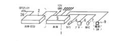
図1は、本発明の第1の実施形態に係るドライブレコーダ1と制御装置2との関係を表す斜視図である。図2は、ドライブレコーダ1を部分的に変更した変更形態の斜視図である。図3は、車両3へのカメラ取付け位置を説明するための図である。図4は、センタ4を表す図であり、図4(a)はセンタ機器構成を表す図であり、図4(b)は、ディスプレイ4aに車両3の走行軌跡、撮像画像およびGセンサ計測値を出力した一態様を表す図である。第1の実施形態では、車両3に予め搭載される運行管理の制御装置2(AVM−ECU2という場合がある)に、ドライブレコーダ1が電気的に接続されて設けられる。たとえば400MHz帯域のデジタル式無線周波数を用いて、制御装置2から車両3の位置、時間および動態情報をセンタ4へ送信可能であり、センタ4は、これらの情報に基づいて、複数の車両3のうち特定車両に配車指示を行うようになっている。またセンタ4は、前記無線周波数などを用いて、制御装置2を介してドライブレコーダ1に画像撮影要求を実施する。ただし適用する無線周波数は400MHz帯域に必ずしも限定されるものではない。たとえば携帯電話機用に割り当てられた周波数帯域を適用する場合もある。デジタル式無線周波数ではなく、アナログ式無線周波数を適用する場合もあり得る。  FIG. 1 is a perspective view showing the relationship between thedrive recorder 1 and thecontrol device 2 according to the first embodiment of the present invention. FIG. 2 is a perspective view of a modified form in which thedrive recorder 1 is partially changed. FIG. 3 is a diagram for explaining a camera mounting position on thevehicle 3. 4 is a diagram showing thecenter 4, FIG. 4 (a) is a diagram showing the center device configuration, and FIG. 4 (b) is adisplay 4a showing a travel locus of thevehicle 3, a captured image, and a G sensor measurement value. It is a figure showing the one aspect | mode which output. In the first embodiment, thedrive recorder 1 is provided by being electrically connected to an operation management control device 2 (sometimes referred to as an AVM-ECU 2) mounted in advance on thevehicle 3. For example, the position, time and dynamic information of thevehicle 3 can be transmitted from thecontrol device 2 to thecenter 4 using a digital radio frequency in the 400 MHz band, and thecenter 4 can transmit a plurality ofvehicles 3 based on the information. Of these, specific vehicles are dispatched. Further, thecenter 4 issues an image photographing request to thedrive recorder 1 via thecontrol device 2 using the radio frequency or the like. However, the applied radio frequency is not necessarily limited to the 400 MHz band. For example, a frequency band allocated for a mobile phone may be applied. An analog radio frequency may be applied instead of a digital radio frequency.

第1の実施形態に係る運転情報記録装置としてのドライブレコーダ1(第1ドラレコ1と称す)は、制御装置2からの車両3の位置、時間および動態情報(これらを情報等と称す)を記録するとともに、予め定める条件が成立した場合に、前記情報等と関連付けて画像および音声情報を記録するように構成されている。センタ機器は、第1ドラレコ1に記録されたこれらの情報を解析可能かつ出力可能に構成されている。  A drive recorder 1 (referred to as first drive recorder 1) as a driving information recording device according to the first embodiment records the position, time and dynamic information (referred to as information etc.) of thevehicle 3 from thecontrol device 2. In addition, when a predetermined condition is satisfied, the image and audio information are recorded in association with the information. The center device is configured to be able to analyze and output these pieces of information recorded in thefirst drive recorder 1.

第1ドラレコ1は、ドライブレコーダ本体5(ドラレコ本体5と称す)、撮像手段であるカメラ6、車室内の音声情報を取得する音声情報取得手段であるマイク7および警告情報を発する情報出力手段であるブザー8を有する。カメラ6およびマイク7は、ドラレコ本体5に電気的に接続されて別体に設けられ、ブザー8はドラレコ本体5に一体に設けられる。当該車両3には少なくとも一台のカメラ6が設けられる。カメラ6はCCDカメラ(CCD:Charge Coupled Device)によって実現される。このカメラ6は、図3の矢符D1で表記する車両前方方向を撮影すべくたとえばルームミラー裏のフロントガラス3aに、図示外のブラケットを介して貼り付けられる。つまりこのカメラ6は車両前方に向けて固定される。第1ドラレコ1では、オプションとして、当該車両3に二台目または三台目のカメラ6を設けることが可能であり、具体的には車室3内の撮影用カメラ6A、または車両後方の撮影用カメラ6Bを設けることも可能である。ドラレコ本体5には、これらのカメラ6を撮像するための撮影スイッチ9が電気的に接続されて別体に設けられる場合もある。  Thefirst drive recorder 1 is a drive recorder main body 5 (referred to as a drive recorder body 5), acamera 6 that is an image pickup means, amicrophone 7 that is a sound information acquisition means for acquiring sound information in the passenger compartment, and an information output means that issues warning information. Abuzzer 8 is provided. Thecamera 6 and themicrophone 7 are electrically connected to thedrive recorder body 5 and provided separately, and thebuzzer 8 is provided integrally with thedrive record body 5. Thevehicle 3 is provided with at least onecamera 6. Thecamera 6 is realized by a CCD camera (CCD: Charge Coupled Device). Thiscamera 6 is affixed to a windshield 3a, for example, on the back of the rearview mirror via a bracket (not shown) so as to photograph the vehicle front direction indicated by the arrow D1 in FIG. That is, thecamera 6 is fixed toward the front of the vehicle. In thefirst draco 1, as an option, a second orthird camera 6 can be provided in thevehicle 3. Specifically, thecamera 6 </ b> A for photographing inside thepassenger compartment 3 or photographing behind the vehicle. It is also possible to provide acamera 6B. There may be a case where the photographing switch 9 for photographing thesecameras 6 is electrically connected to thedorareco body 5 and provided separately.

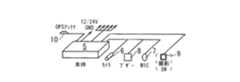
また図2に示すように、ドラレコ本体5に、GPS(GPS:Global Positioning System)アンテナ10および図示外のGPSレシーバなどが付加されたドライブレコーダ1Aを車両に適用することも可能である。  Further, as shown in FIG. 2, a drive recorder 1A in which a GPS (Global Positioning System)antenna 10 and a GPS receiver (not shown) are added to thedorareco body 5 can be applied to the vehicle.

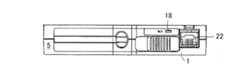
図5はドライブレコーダ1の斜視図であり、図6はドライブレコーダ1の正面図である。ドラレコ本体5には、記録媒体であるCFカード11(CF:Compact Flash)が挿抜可能に構成されている。このCFカード11は、通電しなくても記憶が消えないフラッシュメモリと、外部との入出力を受け持つコントローラ回路とを一枚のカードにまとめた構造になっている。ドラレコ本体5のうち後述する第1RAM12(RAM:Random Access Memory)に、車両周辺画像、車室内のマイクからの音声情報、位置、個人、時間および実空車情報を含む運転情報がエンドレスで順次記録される。予め定める条件が成立した場合に前記CFカード11に、これらの情報の少なくとも一部が記録される。特に、後述する実空車のトリガの場合は、複数の運転情報のうち、音声および実空車情報のみがCFカード11に記録されるようになっている。  FIG. 5 is a perspective view of thedrive recorder 1, and FIG. 6 is a front view of thedrive recorder 1. Thedorareco body 5 is configured such that a CF card 11 (CF: Compact Flash) as a recording medium can be inserted and removed. TheCF card 11 has a structure in which a flash memory that does not lose its memory even when it is not energized, and a controller circuit that is responsible for input / output to / from the outside are combined into a single card. The driving information including the vehicle periphery image, the voice information from the microphone in the vehicle interior, the position, the individual, the time, and the actual empty vehicle information is sequentially recorded in an endless manner in a first RAM 12 (RAM: Random Access Memory) to be described later in thedorareko body 5. The When predetermined conditions are satisfied, at least a part of these pieces of information is recorded on theCF card 11. In particular, in the case of an actual empty vehicle trigger described later, only voice and actual empty vehicle information among a plurality of driving information is recorded on theCF card 11.

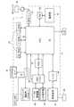
図7は、ドライブレコーダ1、制御装置2およびセンタ4の電気的構成を表すブロック図である。図8は、ドライブレコーダ1の電気的構成を表すブロック図である。図9は、制御装置2の電気的構成を表すブロック図である。ドラレコ本体5は、制御手段としての第1CPU13(CPU:Central Processing Unit)と、第1ROM14(ROM:Read Only Memory)と、記憶手段としての前記第1RAM12と、CFカードインターフェース15と、JPEG IC16(JPEG:Joint Photographic coding Experts Group、IC:Integrated Circuit)と、ビデオスイッチ17と、発光ダイオード18(略称LED:Light Emitting Diode、図5参照)とを有する。ドラレコ本体5は、USBホスト機能を有する手段であるUSB HOST19(USB:Universal Serial Bus)と、USBインタフェース20と、制御装置2との間で情報のやりとりを行う第1通信用ドライバ21と、LCD操作器コネクタ22(LCD:Liquid Crystal Display)と、第1バッファ23と、制御装置2からの電源起動信号を検出する第1回路24と、ウォッチドッグ機能を有する第1ウォッチドッグIC25と、第1電源部26と、Gセンサ27と、車速パルスを集計する図示外のカウンタとをさらに有する。LCD操作器コネクタ22には、後述するメンテナンスモード用のLCD操作器28が接続可能に構成されている。Gセンサ27は、車両3の前後方向および左右方向に作用する重力加速度いわゆるGセンサ出力値を検出するセンサである。当該車両3の運転席に着座した乗務員の正面方向およびその後方を前後方向とし、当該車両3に着座した乗務員の左および右方向を左右方向とする。前後および左右方向に直交する方向を上下方向とする。前記前後方向をY軸方向と定義し、前記左右方向をX軸方向と定義する。X軸方向のGセンサ出力値とY軸方向のGセンサ出力値とは、独立して検出されて記録される。  FIG. 7 is a block diagram showing the electrical configuration of thedrive recorder 1, thecontrol device 2, and thecenter 4. FIG. 8 is a block diagram showing an electrical configuration of thedrive recorder 1. FIG. 9 is a block diagram illustrating an electrical configuration of thecontrol device 2. Thedrive recorder body 5 includes a first CPU 13 (CPU: Central Processing Unit) as control means, a first ROM 14 (ROM: Read Only Memory), thefirst RAM 12 as storage means, aCF card interface 15, and a JPEG IC 16 (JPEG). : Photographic coding Experts Group, IC: Integrated Circuit),video switch 17, and light emitting diode 18 (abbreviation LED: Light Emitting Diode, see FIG. 5). Thedrive recorder 5 includes a USB HOST 19 (USB: Universal Serial Bus) that is a means having a USB host function, aUSB interface 20, afirst communication driver 21 that exchanges information with thecontrol device 2, an LCD A controller connector 22 (LCD: Liquid Crystal Display), afirst buffer 23, afirst circuit 24 for detecting a power activation signal from thecontrol device 2, afirst watchdog IC 25 having a watchdog function, and a first It further has apower supply unit 26, aG sensor 27, and a counter (not shown) that counts vehicle speed pulses. The LCDoperation unit connector 22 is configured to be connectable to anLCD operation unit 28 for maintenance mode, which will be described later. TheG sensor 27 is a sensor that detects a so-called G sensor output value of gravitational acceleration acting in the front-rear direction and the left-right direction of thevehicle 3. The front direction and the rear side of the crew seated in the driver's seat of thevehicle 3 are defined as the front-rear direction, and the left and right directions of the crew seated in thevehicle 3 are defined as the left-right direction. The direction orthogonal to the front-rear and left-right directions is the up-down direction. The front-rear direction is defined as the Y-axis direction, and the left-right direction is defined as the X-axis direction. The G sensor output value in the X-axis direction and the G sensor output value in the Y-axis direction are detected and recorded independently.

前記第1RAM12は第1のSD−RAM29(SD−RAM:Synchronous DRAM)および第2のSD−RAM30を備え、第1のSD−RAM29は、カメラで撮影した生の画像を一旦記録するもので、記録した画像がJPEG形式の画像データに変換される。第2のSD−RAM30は、JPEG形式に変換された画像データ、前記Gセンサ27からのGセンサ出力値および音声などをエンドレスで巡回的に記録するように構成されている。第1CPU13に、第1ROM14、第2のSD−RAM30、CFカードインターフェース15がそれぞれ電気的に接続され、第1CPU13に、JPEG IC16を介して第1のSD−RAM29およびビデオスイッチ17が電気的に接続されている。前記ビデオスイッチ17は、複数のカメラ6,6A(6B)が設けられる場合に所定時間間隔で撮像するカメラ6,6A(6B)を切換えるための切換えスイッチである。第1CPU13には、USB HOST19を介してUSBインタフェース20が電気的に接続されるとともに、通信用ドライバ21、LCD操作器コネクタ22、第1バッファ23、第1ウォッチドッグIC25、Gセンサ27がそれぞれ電気的に接続されている。第1バッファ23は前記第1回路24に電気的に接続される。第1ウォッチドッグIC25には、第1電源部26が電気的に接続される。また第1CPU13は、制御装置2からの電源オン情報に基づいて、主電源である第1電源部26を立ち上げるように構成される。また制御装置2から電源起動信号が得られない場合、制御装置2とは接続されていないものとして、通信用ドライバ21からの入力をスイッチでGPSアンテナ側への入力に切替える。これによって、制御装置2からの位置情報の代わりに単独でGPSからの位置を検出できる。  Thefirst RAM 12 includes a first SD-RAM 29 (SD-RAM: Synchronous DRAM) and a second SD-RAM 30. The first SD-RAM 29 temporarily records a raw image taken by a camera. The recorded image is converted into image data in JPEG format. The second SD-RAM 30 is configured to record endlessly and cyclically the image data converted into the JPEG format, the G sensor output value from theG sensor 27, the sound, and the like. Thefirst ROM 13, the second SD-RAM 30, and theCF card interface 15 are electrically connected to thefirst CPU 13, respectively, and the first SD-RAM 29 and thevideo switch 17 are electrically connected to thefirst CPU 13 via theJPEG IC 16. Has been. Thevideo switch 17 is a change-over switch for switching between thecameras 6 and 6A (6B) that capture images at predetermined time intervals when a plurality ofcameras 6 and 6A (6B) are provided. AUSB interface 20 is electrically connected to thefirst CPU 13 via aUSB HOST 19, and acommunication driver 21, an LCDoperation device connector 22, afirst buffer 23, afirst watchdog IC 25, and aG sensor 27 are electrically connected to thefirst CPU 13. Connected. Thefirst buffer 23 is electrically connected to thefirst circuit 24. A firstpower supply unit 26 is electrically connected to thefirst watchdog IC 25. Thefirst CPU 13 is configured to start up the firstpower supply unit 26 that is the main power supply based on the power-on information from thecontrol device 2. When the power activation signal cannot be obtained from thecontrol device 2, the input from thecommunication driver 21 is switched to the input to the GPS antenna side by a switch, assuming that thecontrol device 2 is not connected. Thus, the position from the GPS can be detected alone instead of the position information from thecontrol device 2.

制御装置2は、AVM用の第2CPU31、第2ROM32および第2RAM33を備えるマイクロコンピュータと、第2バッファ34と、GPS(GPS:Global Positioning System)レシーバ35と、GPSアンテナ36と、ASIC37(ASIC:Application Specific Integrated Circuit)と、第2通信用ドライバ38と、LCD操作器39と、第3バッファ40と、車両3からのHi/Lo信号を検出する第2回路41と、第2ウォッチドッグIC42と、第2電源部43とを有する。第2CPU31に、第2ROM32、第2RAM33がそれぞれ電気的に接続されるとともに、第2バッファ40を介してPCMCIA規格に準拠したカードMが電気的に接続される。第2CPU31に、ASIC37を介して第2通信用ドライバ38が電気的に接続され、この第2通信用ドライバ38に400MHz帯域のデジタル式無線周波数で送受信可能なデジタル無線機45が電気的に接続されている。ところで第1の実施形態では、制御装置2にGPSレシーバ35およびGPSアンテナ36が設けられる構成になっているが、図2に示すように、ドラレコ本体5にGPSレシーバおよびGPSアンテナ10が設けられる構成にすることも可能である。  Thecontrol device 2 includes an AVMsecond CPU 31, asecond ROM 32, and a second RAM 33, asecond buffer 34, a GPS (Global Positioning System)receiver 35, aGPS antenna 36, and an ASIC 37 (ASIC: Application). Specific Integrated Circuit), asecond communication driver 38, anLCD controller 39, athird buffer 40, asecond circuit 41 for detecting a Hi / Lo signal from thevehicle 3, asecond watchdog IC 42, And a secondpower supply unit 43. Asecond ROM 32 and a second RAM 33 are electrically connected to thesecond CPU 31, and a card M conforming to the PCMCIA standard is electrically connected via thesecond buffer 40. Asecond communication driver 38 is electrically connected to thesecond CPU 31 via theASIC 37, and adigital radio 45 capable of transmitting and receiving at a digital radio frequency of 400 MHz band is electrically connected to thesecond communication driver 38. ing. By the way, in 1st Embodiment, although theGPS receiver 35 and theGPS antenna 36 are provided in thecontrol apparatus 2, as shown in FIG. 2, the structure in which the GPS receiver and theGPS antenna 10 are provided in the dorarekomain body 5 is shown. It is also possible to make it.

位置情報、時間情報はGPSアンテナ36およびGPSレシーバ35を用いて取得され、乗務員データはLCD操作器39から入力可能になっている。実空車情報は、運転者で操作がなされる実空車操作手段としての実車/空車メータ44から取得される。実車/空車メータ44には、運転者操作によって作動するスイッチが設けられている。乗客が車内に入り、行き先を確認した時点で運転者により実車側にスイッチのスイッチング状態が操作される。目的地に到着すると、運転者により空車側にスイッチのスイッチング状態が操作され、精算がなされる。  Position information and time information are acquired using theGPS antenna 36 and theGPS receiver 35, and crew data can be input from theLCD controller 39. The actual empty vehicle information is acquired from an actual vehicle /empty vehicle meter 44 as an actual empty vehicle operating means operated by the driver. The actual vehicle /empty vehicle meter 44 is provided with a switch operated by a driver's operation. When the passenger enters the vehicle and confirms the destination, the switching state of the switch is operated to the actual vehicle by the driver. When the vehicle arrives at the destination, the driver operates the switching state of the switch on the empty vehicle side, and payment is made.

これら位置情報や時間情報、乗務員データおよび実空車情報は、一旦第2RAM33に記憶される。センタ4からデジタル無線機45を介して情報送信の要求があると、第2RAM33に記憶されたこれらの情報を、デジタル無線機45を介してセンタ4へ送信する。また定期的に制御装置2が自発的にセンタ4へ送信してもよい。さらに制御装置2はセンタ4からデジタル無線機45を介して配車要求があると、その旨をスピーカSPを介して運転手に伝える。  These position information, time information, crew data, and actual empty vehicle information are temporarily stored in the second RAM 33. When there is a request for information transmission from thecenter 4 via thedigital wireless device 45, the information stored in the second RAM 33 is transmitted to thecenter 4 via thedigital wireless device 45. Moreover, thecontrol apparatus 2 may transmit to thecenter 4 voluntarily regularly. Further, when there is a vehicle allocation request from thecenter 4 via thedigital radio 45, thecontrol device 2 notifies the driver via the speaker SP.

このような基本的な機能を元々制御装置2は有しているので、制御装置2は、得られた位置情報や時間情報、乗務員データおよび実空車情報をドライバ38を介してドライブレコーダ1へシリアル通信ラインSLで送信する。ドライブレコーダ1は、それらの情報を第1通信用ドライバ21を介して受信し、第2のSD−RAM30に記憶する。  Since thecontrol device 2 originally has such a basic function, thecontrol device 2 serializes the obtained position information, time information, crew data and actual vehicle information to thedrive recorder 1 via thedriver 38. It transmits with communication line SL. Thedrive recorder 1 receives the information via thefirst communication driver 21 and stores it in the second SD-RAM 30.

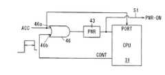
図10は、制御装置2の要部の電気的構成を表すブロック図である。図11は、ドライブレコーダ1の要部の電気的構成を表すブロック図である。図12は、ウォッチドッグパルスが停止または規定の周期で動作しない場合、ハードウェアによりリセットをかける遅延回路を説明する図である。図10に示すように、制御装置2において、論理和回路46つまりOR回路46の入力側一方46aに車両3のアクセサリー電源が接続され、前記OR回路46の入力側他方46bに第2CPU31からの制御信号が供給される。前記OR回路46、第2CPU31間に接続される第2電源部43から、ドライブレコーダ1側に電源オン信号S1が供給される。すなわち図11に示すように、ドライブレコーダ1において、OR回路47の入力側一方47aにアクセサリー電源が接続され、前記OR回路47の入力側他方47bに前記電源オン信号S1が供給される。  FIG. 10 is a block diagram illustrating an electrical configuration of a main part of thecontrol device 2. FIG. 11 is a block diagram showing an electrical configuration of a main part of thedrive recorder 1. FIG. 12 is a diagram for explaining a delay circuit for resetting by hardware when the watchdog pulse is stopped or does not operate at a predetermined cycle. As shown in FIG. 10, in thecontrol device 2, the accessory power source of thevehicle 3 is connected to theinput side 46 a of theOR circuit 46, that is, theOR circuit 46, and thesecond CPU 31 controls theother input side 46 b of theOR circuit 46. A signal is supplied. A power-on signal S1 is supplied from the secondpower supply unit 43 connected between theOR circuit 46 and thesecond CPU 31 to thedrive recorder 1 side. That is, as shown in FIG. 11, in thedrive recorder 1, an accessory power supply is connected to oneinput side 47a of theOR circuit 47, and the power-on signal S1 is supplied to theother input side 47b of theOR circuit 47.

ドライブレコーダ1は、アクセサリー電源から供給されるACC信号がオンまたは制御装置2の電源オンで起動する。またドライブレコーダ1は、ACC信号がオフでかつ、制御装置2の第2電源部43がオフ(図12の立ち下がり信号)になっても、データ記録を実施できるように、ソフトウェアにより終了制御するようになっている。図12に示すように、制御装置2の動作中ソフトウェアでウォッチドッグパルス(図12でWDパルスと表記する)を発生させ、該ウォッチドッグパルスが停止または規定の周期で動作しない場合、ハードウェアによりリセットをかけるようになっている。本実施形態では、第2ウォッチドッグIC42および第2CPU31が遅延回路に相当する。  Thedrive recorder 1 is activated when the ACC signal supplied from the accessory power supply is turned on or thecontrol device 2 is turned on. Further, thedrive recorder 1 performs termination control by software so that data recording can be performed even when the ACC signal is off and the secondpower supply unit 43 of thecontrol device 2 is off (falling signal in FIG. 12). It is like that. As shown in FIG. 12, when a watchdog pulse (denoted as a WD pulse in FIG. 12) is generated by software during operation of thecontrol device 2 and the watchdog pulse is stopped or does not operate at a specified cycle, A reset is applied. In the present embodiment, thesecond watchdog IC 42 and thesecond CPU 31 correspond to a delay circuit.

図13は、ドライブレコーダ1を部分的に変更した変更形態に係る、要部の電気的構成を表すブロック図である。本実施形態では、ドライブレコーダ1においてOR回路47の入力側に、ACC信号、電源オン信号S1が供給されるようになっているが必ずしもこの形態に限定されるものではない。つまり図13に示すように、ドライブレコーダ1においてOR回路47の入力側に、ACC信号、電源オン信号および第1CPU13からの制御信号S2が供給される形態であってもよい。この変更形態であっても、ドライブレコーダ1の動作中ソフトウェアでウォッチドッグパルスを発生させ、該ウォッチドッグパルスが停止または規定の周期で動作しない場合、ハードウェアによりリセットをかけることが可能となる。変更形態では、第1ウォッチドッグIC25および第1CPU13が遅延回路に相当する。  FIG. 13 is a block diagram illustrating an electrical configuration of a main part according to a modified form in which thedrive recorder 1 is partially changed. In the present embodiment, the ACC signal and the power-on signal S1 are supplied to the input side of theOR circuit 47 in thedrive recorder 1, but the present invention is not necessarily limited to this form. That is, as shown in FIG. 13, thedrive recorder 1 may be configured such that the ACC signal, the power-on signal, and the control signal S <b> 2 from thefirst CPU 13 are supplied to the input side of theOR circuit 47. Even in this modified form, when a watchdog pulse is generated by software during operation of thedrive recorder 1 and the watchdog pulse is stopped or does not operate at a predetermined cycle, it can be reset by hardware. In the modified form, thefirst watchdog IC 25 and thefirst CPU 13 correspond to a delay circuit.

図14は、画像情報の一部と位置情報等との関係を表す図である。図15は、Gセンサ出力値に基づいて、静止画像情報が一定間隔δおきにCFカード11に記録される態様を表す図である。第1CPU13は、カメラ6で撮像されドラレコ本体5に入力された入力画像をJPEG IC16によってJPEG変換画像に変換し、その後第1CPU13は、JPEG変換画像を第2のSD−RAM30にエンドレスで順次記録する。このとき一枚の静止画像は、たとえば「画像*.jpg」という形式で記録される。ただし前記「*」は整数である。記録された静止画像の付加情報として、当該車両3のGセンサ出力値、位置、時間、実空車および車速センサ50からの車速情報と、マイク7からの音声情報とを、第2のSD−RAM30にエンドレスで順次記録する。  FIG. 14 is a diagram illustrating a relationship between part of image information and position information. FIG. 15 is a diagram illustrating a mode in which still image information is recorded on theCF card 11 at regular intervals δ based on the G sensor output value. Thefirst CPU 13 converts the input image picked up by thecamera 6 and input to thedrive recorder body 5 into a JPEG converted image by theJPEG IC 16, and then thefirst CPU 13 sequentially records the JPEG converted image in the second SD-RAM 30 in an endless manner. . At this time, one still image is recorded in the format of “image * .jpg”, for example. However, the “*” is an integer. As additional information of the recorded still image, the G sensor output value, position, time, vehicle speed information from the actual sky vehicle and thevehicle speed sensor 50, and voice information from themicrophone 7 are recorded as the second SD-RAM 30. To endlessly.

予め定める記録条件を満たした場合、第1CPU13は、ブザー8に記録開始の合図を出力させる。これとともに第1CPU13は、第2のSD−RAM30に記録されたJPEG変換画像、Gセンサ出力値、位置、時間、実空車および車速センサ50からの車速情報をCFカード11に記録させる。本実施形態では、たとえば1秒間に10枚の静止画像が記録され、1イベント最大30秒間で300枚の静止画像がCFカード11に記録可能に構成されている。1イベントとは、予め定める記録条件を満たした一つの状態と同義である。  When the predetermined recording condition is satisfied, thefirst CPU 13 causes thebuzzer 8 to output a recording start signal. At the same time, thefirst CPU 13 causes theCF card 11 to record the JPEG converted image, G sensor output value, position, time, actual empty vehicle, and vehicle speed information from thevehicle speed sensor 50 recorded in the second SD-RAM 30. In the present embodiment, for example, 10 still images are recorded per second, and 300 still images can be recorded on theCF card 11 per event for a maximum of 30 seconds. One event is synonymous with one state that satisfies a predetermined recording condition.

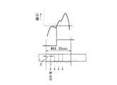
記録条件などについて説明する。図16は、閾値を超過したGセンサ出力値48と、CFカード11に記録される画像情報の記録範囲Rhとの関係を表す図である。記録条件としてGセンサ出力値48が閾値Gmax.またはGmin.を超過すると、閾値超過時点を基準として最大30秒間の記録範囲にわたって、第2のSD−RAMにエンドレスで記録されたJPEG変換画像、そのGセンサ出力値、位置、時間、実空車および車速情報と、マイク7からの音声情報とをCFカード11に記録する。閾値超過時点をトリガ発生時という場合がある。トリガ発生前の記録時間Tbef秒に、トリガ発生後の記録時間Taft秒を加えた時間が、1イベントにおける記録範囲の合計時間に相当する。トリガ発生前5秒以上25秒以下、トリガ発生後5秒以上25秒以下の範囲で最大30秒間を設定可能になっている。The recording conditions will be described. FIG. 16 is a diagram illustrating the relationship between the Gsensor output value 48 that exceeds the threshold and the recording range Rh of the image information recorded on theCF card 11. As a recording condition, the Gsensor output value 48 is a threshold value Gmax. Or Gmin. Exceeding the threshold value, the JPEG converted image recorded in the second SD-RAM endlessly over the recording range of up to 30 seconds, its G sensor output value, position, time, actual empty vehicle and vehicle speed information The voice information from themicrophone 7 is recorded on theCF card 11. The time when the threshold is exceeded may be referred to as a trigger occurrence. The time obtained by adding the recording time Taft seconds after the occurrence of the trigger to the recording time Tbef seconds before the occurrence of the trigger corresponds to the total time of the recording range in one event. A maximum of 30 seconds can be set in a range of 5 seconds to 25 seconds before the trigger occurrence and 5 seconds to 25 seconds after the trigger occurrence.

図17は、Gセンサ出力値の閾値判定方法を説明するための図である。図7、図8も参照しつつ説明する。第1CPU13は、Gセンサの出力を取得し、閾値Gabeを超えたか否かを判定する。Gセンサ27は、前述のようにX、Y軸方向の二軸タイプであり、車両3の前後方向および左右方向の重力加速度を検出可能に構成されている。したがって前後方向の衝突事故だけでなく、左右方向の衝突事故をも確実に検出することができ、その原因を分析することが可能となる。閾値判定は、前後方向の重力加速度と、左右方向の重力加速度とのベクトル和で実施する。この閾値は、設定により任意の値に変更可能になっている。FIG. 17 is a diagram for explaining a threshold determination method for the G sensor output value. This will be described with reference to FIGS. The 1CPU13 obtains the output of the G sensor, determines whether or not exceeding the threshold valueG abe. As described above, theG sensor 27 is a two-axis type in the X and Y axis directions, and is configured to be able to detect the gravitational acceleration in the longitudinal direction and the lateral direction of thevehicle 3. Therefore, not only the longitudinal collision accident but also the lateral collision accident can be reliably detected, and the cause can be analyzed. The threshold determination is performed by the vector sum of the gravitational acceleration in the front-rear direction and the gravitational acceleration in the left-right direction. This threshold value can be changed to an arbitrary value by setting.

本実施形態では、Gセンサ27を内蔵するドラレコ本体5を完全に水平に設置できない状況が考えられるので、Gセンサ27の前後および左右方向のオフセットを補正する処理を行うようになっている。つまり図5に示すように、LCD操作器28をLCD操作器コネクタ22に接続すると、ドラレコ本体5は通常モードから、該ドラレコ本体5を設定、検査するためのメンテナンスモードに移行する。このメンテナンスモードにおいて、Gセンサ27の前後および左右方向のオフセットを補正する処理を実行するようになっている。当該車両3において悪路走行時には、上下方向の振動が不所望に大きくなり、Gセンサ27で前後および左右方向にも重力加速度が検出されることが予想される。したがって悪路走行での上下振動を観測し、誤反応を軽減させる処理をGセンサ出力値に施すようになっている。  In the present embodiment, since the situation in which thedrive body 5 incorporating theG sensor 27 cannot be installed completely horizontally is considered, processing for correcting the offset in the front-rear and left-right directions of theG sensor 27 is performed. That is, as shown in FIG. 5, when theLCD controller 28 is connected to theLCD controller connector 22, thedrive recorder body 5 shifts from the normal mode to a maintenance mode for setting and inspecting thedrive recorder body 5. In this maintenance mode, processing for correcting the front-rear and left-right offsets of theG sensor 27 is executed. When thevehicle 3 travels on a rough road, the vertical vibration is undesirably increased, and it is expected that theG sensor 27 detects gravitational acceleration in the front-rear and left-right directions. Accordingly, the G sensor output value is subjected to processing for observing vertical vibrations on rough roads and reducing false reactions.

図18は、撮影スイッチ9のオン信号S3と、CFカード11に記録される画像情報の記録範囲Rhとの関係を表す図である。記録条件として、乗務員が撮影スイッチ9をオンにして、そのスイッチング態様を切換えると、撮影スイッチオン時点TR1(トリガ発生時と称す)を基準として最大30秒間の記録範囲にわたって、第2のSD−RAM30にエンドレスで記録されたJPEG変換画像、その撮影スイッチオン時点のGセンサ出力値、位置、時間、実空車および車速情報と、マイク7からの音声情報とをCFカード11に記録する。トリガ発生前の記録時間Tbef秒に、トリガ発生後の記録時間Taft秒を加えた時間(Tbef+Taft秒)が、1イベントにおける記録範囲の合計時間に相当する。ただし撮影スイッチ9をトリガとしてJPEG変換画像などをCFカード11に記録する場合には、そのスイッチ操作回数を制限し、所定の操作回数に達すると、以後撮影スイッチ9を操作してもCFカード11に記録しないようにドラレコ本体5を設定することも可能である。FIG. 18 is a diagram illustrating the relationship between the ON signal S3 of the photographingswitch 9 and the recording range Rh of the image information recorded on theCF card 11. As a recording condition, when the crew member turns on the photographingswitch 9 and switches the switching mode, the second SD-RAM 30 extends over a recording range of up to 30 seconds with reference to the photographing switch-on time TR1 (referred to as trigger occurrence). The JPEG conversion image recorded endlessly, the G sensor output value at the time when the photographing switch is turned on, the position, time, actual empty vehicle and vehicle speed information, and the voice information from themicrophone 7 are recorded on theCF card 11. The time (Tbef + Taft seconds) obtained by adding the recording time Taft seconds after the occurrence of the trigger to the recording time Tbef seconds before the occurrence of the trigger corresponds to the total time of the recording range in one event. However, when a JPEG converted image or the like is recorded on theCF card 11 using theshooting switch 9 as a trigger, the number of switch operations is limited, and when the predetermined number of operations is reached, theCF card 11 is operated even if theshooting switch 9 is operated thereafter. It is also possible to set thedrive recorder body 5 so as not to record.

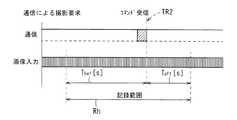
図19は、通信による撮影要求コマンド受信と、CFカード11に記録される画像情報の記録範囲Rhとの関係を表す図である。図7も参照しつつ説明する。記録条件として、センタ4から制御装置2に無線周波数による画像撮影要求があると、ドラレコ本体5の第1CPU13はその信号をコマンド受信する。そうすると、コマンド受信時TR2(トリガ発生時と称す)を基準として最大30秒間の記録範囲にわたって、第2のSD−RAM30にエンドレスで記録されたJPEG変換画像、そのコマンド受信時のGセンサ出力値、位置、時間、実空車および車速情報と、マイク7からの音声情報とをCFカード11に記録する。トリガ発生前の記録時間Tbef秒に、トリガ発生後の記録時間Taft秒を加えた時間(Tbef+Taft秒)が、1イベントにおける記録範囲の合計時間に相当する。たとえば運行データの一つである車速パルスに基づいて求められる当該車両3の速度が、予め定める規定速度よりも大となることをセンタ4が判断すると、センタ4からの画像記録要求が実施される。なお前記トリガ発生に起因するパラメータは、車速パルスだけに限定されるものではない。たとえば定周期記録、急加速、急減速および急ハンドルの少なくともいずれか一方の運行データに基づいて、センタ4から画像記録要求が実施される場合もあり得る。これら複数の運行データを用いることで、センタ4において、乗務員個人の詳細な運転指導を実施することが可能となる。FIG. 19 is a diagram illustrating the relationship between the reception of a shooting request command through communication and the recording range Rh of image information recorded on theCF card 11. This will be described with reference to FIG. As a recording condition, if there is a radio frequency image capturing request from thecenter 4 to thecontrol device 2, thefirst CPU 13 of thedrive recorder body 5 receives the signal as a command. Then, a JPEG conversion image recorded endlessly in the second SD-RAM 30 over a recording range of up to 30 seconds with reference to TR2 (referred to as trigger occurrence) at the time of command reception, the G sensor output value at the time of command reception, The position, time, actual empty vehicle and vehicle speed information, and voice information from themicrophone 7 are recorded on theCF card 11. The time (Tbef + Taft seconds) obtained by adding the recording time Taft seconds after the occurrence of the trigger to the recording time Tbef seconds before the occurrence of the trigger corresponds to the total time of the recording range in one event. For example, when thecenter 4 determines that the speed of thevehicle 3 obtained based on a vehicle speed pulse that is one of the operation data is higher than a predetermined speed, an image recording request from thecenter 4 is executed. . The parameter resulting from the generation of the trigger is not limited to the vehicle speed pulse. For example, an image recording request may be executed from thecenter 4 based on operation data of at least one of periodic recording, sudden acceleration, sudden deceleration, and sudden handle. By using these plurality of operation data, it becomes possible to carry out detailed driving guidance for the crew members at thecenter 4.

図20は、実車/空車メータ44からのHi/Lo信号S4に基づいて、CFカード11に記録される音声情報の記録範囲が規定される態様を表す図である。この音声情報の記録条件として、空車状態から実車状態に切換わるHi信号が出力されると、このHi信号が出力される時点TR3よりもTbef秒(Tbef秒は、たとえば数十秒)前から、取得手段である第2のSD−RAM30に記録された音声情報、実空車および車速情報をCFカード11に記録していく。この記録状態で実車状態から空車状態に切換わるLo信号が出力されると、このLo信号が出力された時点TR4よりもTaft秒(Taft秒は、たとえば数十秒)経過した時点まで音声情報などをCFカード11に記録する。実車/空車メータ44からの信号は、制御装置2が検出しているので、制御装置2とのシリアル通信によりドライブレコーダ1はその実空車状態を検出することができる。なお制御装置2と連携していない場合は、ドライブレコーダ1の外部スイッチとして実車/空車メータ44のメータのオン/オフ信号を取り込むようにすればよい。FIG. 20 is a diagram showing an aspect in which the recording range of the audio information recorded on theCF card 11 is defined based on the Hi / Lo signal S4 from the actual vehicle /empty vehicle meter 44. As a recording condition of the audio information, when a Hi signal for switching from an empty vehicle state to an actual vehicle state is output, Tbef seconds (Tbef seconds is several tens of seconds, for example) before the time point TR3 when the Hi signal is output From the above, the voice information, the actual sky vehicle, and the vehicle speed information recorded in the second SD-RAM 30 as the acquisition means are recorded in theCF card 11. When the Lo signal for switching from the actual vehicle state to the empty vehicle state is output in this recording state, the sound is output until Taft seconds (Taft seconds is, for example, several tens of seconds) from the time point TR4 when the Lo signal is output. Information and the like are recorded on theCF card 11. Since thecontrol device 2 detects the signal from the actual vehicle /empty vehicle meter 44, thedrive recorder 1 can detect the actual empty vehicle state by serial communication with thecontrol device 2. If thecontrol device 2 is not linked, an on / off signal of the meter of the actual vehicle /empty meter 44 may be taken in as an external switch of thedrive recorder 1.

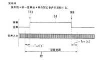
図21は、実車/空車メータ44からのHi信号が出力される時点の前後にわたって画像情報が記録され、Lo信号が出力される時点の前後にわたって画像情報が記録される態様を表す図である。記録条件として、空車状態から実車状態に切換わるHi信号が出力されると、このHi信号が出力される時点TR3(第1トリガ発生時と称す)を基準として最大30秒間の記録範囲にわたって、第2のSD−RAM30にエンドレスで記録された情報のうち、音声情報、実空車情報をCFカード11に記録する。第1トリガ発生前の記録時間Tbef秒に、第1トリガ発生後の記録時間Taft秒を加えた時間Rh(Tbef+Taft秒)が、1イベントにおける記録範囲の合計時間に相当する。第1トリガ発生前5秒以上25秒以下、第1トリガ発生後5秒以上25秒以下の範囲で最大30秒間を設定可能になっている。FIG. 21 is a diagram illustrating a mode in which image information is recorded before and after the time point when the Hi signal is output from the actual vehicle /empty vehicle meter 44, and image information is recorded before and after the time point when the Lo signal is output. As a recording condition, when a Hi signal for switching from an empty vehicle state to an actual vehicle state is output, a recording range of a maximum of 30 seconds is used with reference to a time point TR3 (referred to as the occurrence of the first trigger) at which this Hi signal is output. Among the information recorded endlessly in the SD-RAM 30 of 2, voice information and actual empty vehicle information are recorded on theCF card 11. The time Rh (Tbef + Taft seconds) obtained by adding the recording time Taft seconds after the first trigger to the recording time Tbef seconds before the first trigger corresponds to the total time of the recording range in one event. A maximum of 30 seconds can be set in a range from 5 seconds to 25 seconds before the first trigger occurrence and from 5 seconds to 25 seconds after the first trigger occurrence.

さらに記録条件として、実車状態から空車状態に切換わるLo信号が出力されると、このLo信号が出力される時点TR4(第2トリガ発生時と称す)を基準として最大30秒間の記録範囲にわたって、第2のSD−RAM30に記録された情報のうち、音声情報、実空車情報をCFカード11に記録する。第2トリガ発生前の記録時間Tbef秒に、第2トリガ発生後の記録時間Taft秒を加えた時間Rh(Tbef+Taft秒)が、1イベントにおける記録範囲の合計時間に相当する。第2トリガ発生前5秒以上25秒以下、第2トリガ発生後5秒以上25秒以下の範囲で最大30秒間を設定可能になっている。Further, as a recording condition, when a Lo signal for switching from an actual vehicle state to an empty vehicle state is output, over a recording range of up to 30 seconds with reference to a time point TR4 (referred to as the second trigger occurrence) at which this Lo signal is output, Of the information recorded in the second SD-RAM 30, voice information and actual empty vehicle information are recorded in theCF card 11. A time Rh (Tbef + Taft seconds) obtained by adding a recording time Taft seconds after the occurrence of the second trigger to the recording time Tbef seconds before the occurrence of the second trigger corresponds to the total time of the recording range in one event. A maximum of 30 seconds can be set in a range from 5 seconds to 25 seconds before the second trigger occurrence and from 5 seconds to 25 seconds after the second trigger occurrence.

図22は、ドライブレコーダ1において、トリガの各種とりこみについて説明するブロック図である。本実施形態では、ドライブレコーダ1は、実空車情報を該ドライブレコーダ1に付設のスイッチなどで直接入力するのではなく、制御装置2からのシリアル通信から取得し、それをトリガとして記録する。したがってトリガ入力は、Gセンサ27、通信(センタ4、実空車)、撮影スイッチおよび外部スイッチ49となる。  FIG. 22 is a block diagram for explaining various trigger acquisitions in thedrive recorder 1. In the present embodiment, thedrive recorder 1 does not directly input the actual empty vehicle information with a switch attached to thedrive recorder 1, but acquires it from serial communication from thecontrol device 2 and records it as a trigger. Therefore, the trigger input is theG sensor 27, communication (center 4, actual empty vehicle), photographing switch, andexternal switch 49.

制御装置2からの情報は定期的に送信され、時間軸上では定期的に監視している状態となる。ただし通信では、割り込みとしてのトリガとなる。つまりセンタ4からのトリガ、実空車のトリガは割り込みとなる。外部スイッチ49入力は、他のスイッチのオンオフ信号を入力可能であるので、実空車スイッチのオンオフ信号を当該外部スイッチ入力として採用してもよいし、また、撮影スイッチ(運転者による強制スイッチ)のオンオフ信号を当該外部スイッチ入力として採用してもよい。外部スイッチ入力はトリガおよび状態の両方を検知できる。たとえば実空車の場合、実空車の変化をトリガとして入力するとともに、その実空車の状態を記録のために取り込むことができる。  Information from thecontrol device 2 is periodically transmitted, and is periodically monitored on the time axis. However, in communication, it becomes a trigger as an interrupt. That is, the trigger from thecenter 4 and the trigger of the actual empty vehicle are interrupted. Since the on / off signal of the other switch can be input to theexternal switch 49 input, the on / off signal of the actual empty vehicle switch may be adopted as the external switch input, or the photographing switch (forced switch by the driver) An on / off signal may be adopted as the external switch input. External switch inputs can detect both triggers and conditions. For example, in the case of an actual empty vehicle, a change in the actual empty vehicle can be input as a trigger, and the state of the actual empty vehicle can be captured for recording.

図23は、運行データの閾値に基づいて警告情報を発する態様を表す図である。当該車両3の速度、定周期記録、急加速、急減速および急ハンドルの少なくともいずれか一方の運行データに基づいて、第1CPU13が当該車両3の異常運転を検出すると、ブザー8によって乗務員に警告情報を通知する。この警告情報通知後、異常運転が継続している間はたとえば30秒毎に警告する。ただし第1CPU13は、センタ4から当該車両3に配車指示中ブザー8による警告を禁止する。異常運転であるか否かの判定基準は、予めCFカード11で指定する。図23に示すように、異常検出閾値の上限E1および下限E2、異常判定時間Teがパラメータとして規定される。上限オーバは、予め定める「異常判定時間」以上継続したときに、異常運転であると判断する。本実施形態ではブザー8によって警告情報を通知しているが、これに限定されるものではない。制御装置2または第1ドラレコ1に情報出力手段としてスピーカSP(図7参照)を設け、該スピーカSPから音声合成出力(たとえば「規定の速度を超過しています。減速してください」などの音声合成出力)をすることも可能である。  FIG. 23 is a diagram illustrating a mode in which warning information is issued based on a threshold of operation data. When thefirst CPU 13 detects an abnormal operation of thevehicle 3 based on the operation data of at least one of the speed, fixed period recording, sudden acceleration, sudden deceleration, and sudden handle of thevehicle 3, warning information is sent to the crew by thebuzzer 8. To be notified. After the warning information is notified, a warning is given every 30 seconds while the abnormal operation continues. However, thefirst CPU 13 prohibits warning by thebuzzer 8 during the dispatch instruction from thecenter 4 to thevehicle 3. A criterion for determining whether or not the vehicle is in abnormal operation is designated in advance using theCF card 11. As shown in FIG. 23, the upper limit E1 and lower limit E2 of the abnormality detection threshold and the abnormality determination time Te are defined as parameters. When the upper limit is exceeded for a predetermined “abnormality determination time” or more, it is determined that the operation is abnormal. In the present embodiment, the warning information is notified by thebuzzer 8, but the present invention is not limited to this. A speaker SP (see FIG. 7) is provided as an information output means in thecontrol device 2 or thefirst drive recorder 1, and voice synthesis output (for example, “exceeding the specified speed. Please decelerate”) is output from the speaker SP. (Composite output) is also possible.

急加速、急減速に基づいて異常運転を検知する場合について説明する。第1CPU13は、たとえば0.1秒毎に車速パルスによって当該車両3の速度つまり車速を取得し、1秒間の加速度にて判定する。第1CPU13は、この加速度が判定値を超えた場合に、ブザー8によって乗務員に警告情報を通知し、該加速度をCFカード11に記録する。第1CPU13は、指定の加速度以上の場合には「急加速」と判定し、指定の減速度以上の場合には「急減速」と判定する。判定基準となる加速度、減速度は、実車/空車毎の二種類を設定可能になっている。  A case where abnormal operation is detected based on sudden acceleration and sudden deceleration will be described. Thefirst CPU 13 acquires the speed of thevehicle 3, that is, the vehicle speed by a vehicle speed pulse every 0.1 second, for example, and makes a determination based on an acceleration of 1 second. When the acceleration exceeds the determination value, thefirst CPU 13 notifies the crew member of warning information by thebuzzer 8 and records the acceleration on theCF card 11. Thefirst CPU 13 determines “rapid acceleration” when the acceleration is greater than or equal to the specified acceleration, and determines “rapid deceleration” when the acceleration is greater than or equal to the specified deceleration. Two kinds of acceleration / deceleration as judgment criteria can be set for each actual vehicle / empty vehicle.

速度超過によって異常運転を検知する場合について説明する。第1CPU13は、たとえば0.1秒毎に車速パルスによって車速を取得し、規定の速度オーバ判定速度を超えてかつ規定の警告開始時間を経過した場合に、ブザー8によって乗務員に警告情報を通知する。車速が規定の速度オーバ判定速度を超え、異常判定時間Teを経過を経過した場合には、ブザー8によって警告情報を通知するとともに、該車速3をCFカード11に記録する。車速が速度オーバ判定速度以下になったが、一般道路か高速道路かの道路区分がいずれか一方から他方に変わったとき、速度オーバを解除するようになっている。判定速度、警告開始時間は、前記道路区分毎の二種類を設定可能になっている。  A case where abnormal operation is detected due to overspeed will be described. Thefirst CPU 13 acquires the vehicle speed by a vehicle speed pulse, for example, every 0.1 second, and notifies the crew member of warning information by thebuzzer 8 when the predetermined speed over determination speed is exceeded and the predetermined warning start time has elapsed. . When the vehicle speed exceeds the specified speed over determination speed and the abnormality determination time Te has elapsed, warning information is notified by thebuzzer 8 and thevehicle speed 3 is recorded on theCF card 11. When the vehicle speed is equal to or less than the overspeed determination speed, but the road classification of the general road or the highway is changed from one to the other, the overspeed is canceled. Two types of determination speed and warning start time can be set for each road segment.

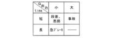
図24は、Gセンサ出力値と検知時間との関係を表す図である。図25は、Gセンサ出力値の大小とその検知時間との関係に基づく傾向を表す図表である。第1CPU13は、CFカード11の記録容量に必要十分な空き容量がなく、該CFカード11にすでに記録したGセンサ出力値が新たに検出されるGセンサ出力値よりも小さいとき、すでに記録したGセンサ出力値を消去し、該検出されるGセンサ出力値をCFカード11に記録させる制御を行う。CFカード11の記録容量の空き容量が必要十分であれば、CFカード11にすでに記録したGセンサ出力値が新たに検出されるGセンサ出力値よりも小さいときであっても、すでに記録したGセンサ出力値を消去することなく、該検出されるGセンサ出力値をCFカード11に記録させるようになっている。  FIG. 24 is a diagram illustrating the relationship between the G sensor output value and the detection time. FIG. 25 is a chart showing a tendency based on the relationship between the magnitude of the G sensor output value and its detection time. When thefirst CPU 13 does not have the necessary and sufficient free space for the recording capacity of theCF card 11 and the G sensor output value already recorded on theCF card 11 is smaller than the newly detected G sensor output value, thefirst CPU 13 Control is performed to erase the sensor output value and record the detected G sensor output value on theCF card 11. If the free space of the recording capacity of theCF card 11 is necessary and sufficient, even if the G sensor output value already recorded on theCF card 11 is smaller than the newly detected G sensor output value, the already recorded G The detected G sensor output value is recorded on theCF card 11 without erasing the sensor output value.

前記Gセンサ出力値が小さく(たとえば0.4G以上2G未満)、その検知時間が短い(たとえば数十ミリsec)場合には、当該車両3が段差または悪路などを通過したことを意味する。Gセンサ出力値が小さく、その検知時間が長い(たとえば100ミリsec以上)場合には、当該車両3が急ブレーキをかけたことを意味する。そしてGセンサ出力値が大きく(たとえば2G以上)、その検知時間が短い場合には、当該車両3が事故を起こしたことを意味する。本件出願人は、このようなGセンサ出力値の大小とその検知時間との関係に基づく傾向のデータを実験などによって、センタ機器のメモリなどにストアしている。  If the G sensor output value is small (for example, 0.4 G or more and less than 2 G) and the detection time is short (for example, several tens of milliseconds), it means that thevehicle 3 has passed through a step or a rough road. If the G sensor output value is small and the detection time is long (for example, 100 milliseconds or more), it means that thevehicle 3 has suddenly braked. When the G sensor output value is large (for example, 2G or more) and the detection time is short, it means that thevehicle 3 has caused an accident. The applicant of the present application stores trend data based on the relationship between the magnitude of the G sensor output value and its detection time in the memory of the center device or the like through experiments or the like.

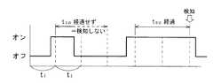
図26は、Gセンサと外部スイッチ検出による基本動作を表すフローチャートである。図27は、Gセンサ出力の閾値とその判定時間との関係を表す図である。図28は、Hi/Lo信号とその判定時間との関係を表すタイミングチャートである。アクセサリー電源から供給されるACC信号がオンまたは制御装置2の電源オンとなる条件で、本フローが開始する。開始後ステップa1において、第1CPU13は、Gセンサ27の定期的な感知タイミングt1(t1は、たとえば10ミリsec)経過したか否かを判断する(図27参照)。「否」との判断でステップa2に移行する。t1経過したとの判断でステップa3に移行して、第1CPU13は、Gセンサ出力値を第2のSD−RAM30に記録させ、ステップa4にてそのGセンサ出力値が閾値よりも大か否かを判断する。「否」との判断でステップa2に戻る。  FIG. 26 is a flowchart showing a basic operation by G sensor and external switch detection. FIG. 27 is a diagram illustrating the relationship between the threshold of the G sensor output and the determination time. FIG. 28 is a timing chart showing the relationship between the Hi / Lo signal and its determination time. This flow starts under the condition that the ACC signal supplied from the accessory power supply is turned on or thecontrol device 2 is turned on. In step a1 after the start, thefirst CPU 13 determines whether or not the periodic sensing timing t1 (t1 is, for example, 10 milliseconds) of theG sensor 27 has elapsed (see FIG. 27). If the determination is “NO”, the process proceeds to step a2. When it is determined that t1 has elapsed, thefirst CPU 13 records the G sensor output value in the second SD-RAM 30 and determines whether or not the G sensor output value is larger than the threshold value in step a4. Judging. If the determination is “NO”, the process returns to step a2.

「否」との判断でステップa5に移行し、第1CPU13は、予め定める閾値判定時間Tg経過したか否かを判断する。閾値判定時間Tgは、感知タイミングt1よりも大きく設定される。Gセンサ出力値が閾値を超えた時点から閾値判定時間Tgの計時が開始され、閾値を超えている連続時間が時間Tgに達すると、閾値判定時間Tg経過したと判断する。閾値判定時間Tg経過していないと判断されると、ステップa2に戻る。閾値判定時間Tg経過したと判断されると、ステップa6に移行する。ここで第1CPU13は、当該車両3が危険運転をしている旨検知する。次にステップa7に移行して第1CPU13は、第2のSD−RAM30に記録された画像情報をCFカード11に記録させる。その後ステップa1に戻る。このような閾値判定時間Tgを設けることで、ノイズ等の誤動作を防止することができる。  When the determination is “NO”, the process proceeds to step a5, and thefirst CPU 13 determines whether or not a predetermined threshold determination time Tg has elapsed. The threshold determination time Tg is set larger than the sensing timing t1. Timing of the threshold determination time Tg is started from the time when the G sensor output value exceeds the threshold, and when the continuous time exceeding the threshold reaches the time Tg, it is determined that the threshold determination time Tg has elapsed. If it is determined that the threshold determination time Tg has not elapsed, the process returns to step a2. If it is determined that the threshold determination time Tg has elapsed, the process proceeds to step a6. Here, thefirst CPU 13 detects that thevehicle 3 is driving dangerously. Next, proceeding to step a7, thefirst CPU 13 causes theCF card 11 to record the image information recorded in the second SD-RAM 30. Thereafter, the process returns to step a1. By providing such a threshold determination time Tg, malfunctions such as noise can be prevented.

ステップa2において、第1CPU13は、外部スイッチ49の定期的な感知タイミングt2(t2は、たとえば100ミリsec)経過したか否かを判断する(図28参照)。「否」との判断でステップa1に戻る。t2経過したとの判断でステップa8に移行して、第1CPU13は外部スイッチ49がオンしたか否かを判断し、「否」との判断でステップa1に戻る。オンしたと判断されるとステップa9に移行し、第1CPU13は、予め定める信号判定時間Tswしたか否かを判断する。この信号判定時間Tswは、感知タイミングt2よりも大きく設定される。オフからオンに切換えられた時点から信号判定時間Tswの計時が開始され、オンとなっている連続時間が時間Tswに達すると、信号判定時間Tsw経過したと判断する。信号判定時間Tsw経過していないと判断されると、ステップa1に戻る。信号判定時間Tsw経過したと判断されると、ステップa10に移行して第1CPU13は外部スイッチ49を検知した後、ステップa7に移行する。前記信号判定時間Tswを設けることで、ノイズ等の誤動作を防止することができる。  In step a2, thefirst CPU 13 determines whether or not the periodic sensing timing t2 of the external switch 49 (t2 is, for example, 100 milliseconds) has elapsed (see FIG. 28). When the determination is “NO”, the process returns to step a1. The process proceeds to step a8 when it is determined that t2 has elapsed, and thefirst CPU 13 determines whether or not theexternal switch 49 is turned on, and returns to step a1 when it is determined as “NO”. If it is determined that the signal is turned on, the process proceeds to step a9, and thefirst CPU 13 determines whether or not a predetermined signal determination time Tsw has been reached. This signal determination time Tsw is set larger than the sensing timing t2. Timing of the signal determination time Tsw is started from the time when the signal is switched from off to on, and when the continuous continuous time reaches the time Tsw, it is determined that the signal determination time Tsw has elapsed. If it is determined that the signal determination time Tsw has not elapsed, the process returns to step a1. If it is determined that the signal determination time Tsw has elapsed, the process proceeds to step a10, thefirst CPU 13 detects theexternal switch 49, and then proceeds to step a7. By providing the signal determination time Tsw, malfunctions such as noise can be prevented.

図29は、音声データを記録する処理を表すフローチャートであり、図29(a)は、実空車変化前後にわたって音声データを記録する処理を表すフローチャート、図29(b)は、実車中の音声データを記録する処理を表すフローチャートである。アクセサリー電源から供給されるACC信号がオンまたは制御装置2の電源オンとなる条件で、本フローが開始する。図29(a)に示すように、開始後ステップb1で第1CPU13は、音声データ(音声情報と同義)を第2のSD−RAM30にエンドレスで記録させる。次にステップb2に移行して、第1CPU13は制御装置2からの信号に基づき実空車スイッチのオンオフを検出する。つまり制御装置2からは実/空車状態しか送ってこないので、ドライブレコーダ1側で実車、空車が変化したことを検出する。  FIG. 29 is a flowchart showing a process for recording voice data, FIG. 29 (a) is a flowchart showing a process for recording voice data before and after the actual empty vehicle change, and FIG. 29 (b) is a voice data in the actual vehicle. It is a flowchart showing the process which records. This flow starts under the condition that the ACC signal supplied from the accessory power supply is turned on or thecontrol device 2 is turned on. As shown in FIG. 29 (a), thefirst CPU 13 causes the second SD-RAM 30 to endlessly record audio data (synonymous with audio information) in step b1 after the start. Next, proceeding to step b2, thefirst CPU 13 detects on / off of the actual empty vehicle switch based on the signal from thecontrol device 2. That is, since only the actual / empty state is sent from thecontrol device 2, it is detected on thedrive recorder 1 side that the actual vehicle and the empty vehicle have changed.

ドライブレコーダ1ではステータスを監視するので、あるタイミングでは空車を検出したなら、これを記憶しておき、その次のタイミングで実車を検出したなら、記憶しておいた「空車」の情報と、今回検出した「実車」の情報との比較により、「空車から実車」に変化したことをドライブレコーダ1が検出できる。このようにしてドライブレコーダ1は、間接的に実空車スイッチのオンオフを検出可能になっている。  Since thedrive recorder 1 monitors the status, if an empty vehicle is detected at a certain timing, it is stored, and if an actual vehicle is detected at the next timing, the stored “empty vehicle” information and this time By comparing with the detected “actual vehicle” information, thedrive recorder 1 can detect that the vehicle has changed from “empty to actual vehicle”. In this way, thedrive recorder 1 can indirectly detect on / off of the actual empty vehicle switch.

ステップb2において「否」との判断でステップb1に戻る。変化したとの判断でステップb3に移行し、第1CPU13は、実車と判断された時点より前の空車時間(Tbef秒)と実車後時間(Taft秒)とを含む経過時間であって、実/空スイッチ44のスイッチング態様の変化前後x秒(x秒は、たとえば30秒)経過したか否かを判断する。「否」との判断でステップb1に戻る。経過したとの判断で、第1CPU13は、前記変化前後x秒(つまり図21で表記する時間Rh)にわたる第2のSD−RAM30に記憶された音声データをCFカード11に記録させる。その後ステップb1に戻る。If it is determined as “NO” in step b2, the process returns to step b1. The process proceeds to step b3 when it is determined that the time has changed, and thefirst CPU 13 is an elapsed time including an empty time (Tbef seconds) and a time after the actual vehicle (Taft seconds) before the time point when the actual vehicle is determined, It is determined whether or not x seconds (x seconds is 30 seconds, for example) have passed before and after the change of the switching mode of the real /empty switch 44. If the determination is “NO”, the process returns to step b1. When determining that the time has elapsed, thefirst CPU 13 causes theCF card 11 to record the audio data stored in the second SD-RAM 30 over x seconds before and after the change (that is, the time Rh shown in FIG. 21). Thereafter, the process returns to step b1.

実車中の音声データをCFカード11に記録させる処理を実行する場合もある。図29(b)に示すように、前記と同じ開始条件でステップc1に移行して、音声データを第2のSD−RAM30にエンドレスで記録させる。次にステップc2で、第1CPU13は制御装置2からの信号に基づき実空車スイッチのオンオフを検出する。つまり制御装置2からは実/空車状態しか送ってこないので、前記ステップb2と同様にドライブレコーダ1側で実車、空車が変化したことを検出する。  There is a case where a process for recording the voice data in the actual vehicle on theCF card 11 is executed. As shown in FIG. 29B, the process proceeds to step c1 under the same start condition as described above, and the audio data is recorded endlessly in the second SD-RAM 30. Next, in step c2, thefirst CPU 13 detects on / off of the actual empty vehicle switch based on the signal from thecontrol device 2. That is, since only the actual / empty state is sent from thecontrol device 2, it is detected on thedrive recorder 1 side that the actual vehicle and the empty vehicle have changed, as in step b2.

ステップc2で「否」との判断でステップc1に戻る。空車から実車に変化したとの判断でステップc3に移行する。ここで第1CPU13は、空車状態から実車状態に切換わる信号が出力される時点よりもx1秒(図20ではTbef秒前から第2のSD−RAM30にエンドレスで記録された音声データをCFカード11に記録させる。次にステップc4で第1CPU13は、CFカード11に実車判断後の音声データを継続的に追加記録させる。次にステップc5において、第1CPU13は実車、空車が変化したか否かを判断する。「否」との判断でステップc4に戻る。ステップc5で実車、空車が変化したとの判断でステップc6に移行し、第1CPU13は、CFカード11に空車判断後の音声データを追加記録させる。その後ステップc7に移行して、第1CPU13は、実車状態から空車状態に切換わる信号が出力される時点よりもx2秒(図20ではTaft秒)経過したか否かを判断する。「否」との判断でステップc6に戻る。x2秒経過したとの判断でステップc1に戻る。If “NO” is determined in step c2, the process returns to step c1. If it is determined that the vehicle has changed from an empty vehicle to an actual vehicle, the process proceeds to step c3. Here, thefirst CPU 13 reads the voice data recorded in the second SD-RAM 30 endlessly in the second SD-RAM 30 from the time point when the signal for switching from the empty state to the actual vehicle state is output (in FIG. 20, Tbef seconds). Next, in step c4, thefirst CPU 13 continuously records the voice data after the actual vehicle determination in theCF card 11. Next, in step c5, thefirst CPU 13 determines whether the actual vehicle and the empty vehicle have changed. If it is determined as “NO”, the process returns to step c4, and if it is determined in step c5 that the actual vehicle and the empty vehicle have changed, the process proceeds to step c6, and thefirst CPU 13 stores the audio data after the empty vehicle determination in theCF card 11. After that, the process proceeds to step c7, where thefirst CPU 13 x2 seconds from the time when the signal for switching from the actual vehicle state to the empty vehicle state is output. 20 (Taft seconds in FIG. 20) is determined, the process returns to step c6 if “no” is determined, and the process returns to step c1 if x2 seconds have elapsed.

図30は、AVM−ECUで合成音声を出力する第1の処理を表すフローチャートである。アクセサリー電源から供給されるACC信号がオンまたは制御装置2の電源オンとなる条件で、本フローが開始する。開始後ステップd1において、第1CPU13が当該車両3の危険運転を検知すると、ステップd2に移行して第1CPU13は、制御装置2の第2CPU31に警告音声出力要求を行う。  FIG. 30 is a flowchart showing a first process of outputting synthesized speech by the AVM-ECU. This flow starts under the condition that the ACC signal supplied from the accessory power supply is turned on or thecontrol device 2 is turned on. When thefirst CPU 13 detects a dangerous driving of thevehicle 3 in step d1 after the start, the process proceeds to step d2 and thefirst CPU 13 makes a warning sound output request to thesecond CPU 31 of thecontrol device 2.

制御装置2側において、ステップE1で第2CPU31が警告音声出力要求を受信すると、ステップEoutにおいて、第2CPU31はスピーカSP(図7参照)に音声合成(たとえば「規定の速度を超過しています。減速してください」などの音声合成)を出力させる。当該車両3がセンタ4から配車指示受信中(ステップE2:YES)は、第2CPU31はスピーカSPに音声を出力させることなく本処理を終了する。配車指示受信中でなければスピーカSPに音声合成を出力させる。  On thecontrol device 2 side, when thesecond CPU 31 receives the warning voice output request at step E1, at step Eout, thesecond CPU 31 synthesizes voice to the speaker SP (see FIG. 7). Please output "speech synthesis". While thevehicle 3 is receiving a dispatch instruction from the center 4 (step E2: YES), thesecond CPU 31 ends the present process without causing the speaker SP to output sound. If the vehicle dispatch instruction is not being received, the speech synthesis is output to the speaker SP.

図31は、AVM−ECUで合成音声を出力する第2の処理を表すフローチャートである。制御装置2側において、ステップE1で第2CPU31が警告音声出力要求を受信するとステップEmに移行し、第2CPU31は、実車/空車メータ44から現在実車中か否かを判断する。「否」との判断でステップEoutに移行し、第2CPU31はスピーカSPに音声合成を出力させる。ステップEmで実車中と判断されると、第2CPU31はスピーカSPに音声を出力させることなく本処理を終了する。  FIG. 31 is a flowchart showing a second process of outputting synthesized speech by the AVM-ECU. On thecontrol device 2 side, when thesecond CPU 31 receives a warning sound output request in step E1, the process proceeds to step Em, and thesecond CPU 31 determines whether or not the actual vehicle is currently in the actual vehicle /empty vehicle meter 44. If the determination is “NO”, the process proceeds to step Eout, and thesecond CPU 31 causes the speaker SP to output speech synthesis. If it is determined in step Em that the vehicle is in the actual vehicle, thesecond CPU 31 ends this process without causing the speaker SP to output sound.

以上説明した本実施形態に係るドライブレコーダ1によれば、第2のSD−RAM30に複数の運転情報(画像、G値、位置、時間、実空車、車速、音声など)をエンドレスで記録する。実空車以外のトリガ(Gセンサなど)の場合は、画像、G値、位置、時間、実空車、車速、音声をカードに記録する。実空車のトリガの場合は、そのうち、音声・実空車のみをCFカード11に記録する。つまり実空車では、乗客に対する運転者の接客態度を見るため、必要とする運転情報は車内のマイクからの運転者の音声、実空車情報で充分であり、画像や車速などは不要である。なぜなら、実空車変化時の運転者の乗客に対する接客態度は、運転者の音声でわかるためである。したがってCFカード11の空き容量を極力確保できる。このように複数のトリガをCFカード11に取り込むにあたっても、実空車に最適な運転情報を取り込み、記録容量の無駄をなくすことが可能となる。  According to thedrive recorder 1 according to the present embodiment described above, a plurality of driving information (image, G value, position, time, actual sky vehicle, vehicle speed, voice, etc.) is recorded endlessly in the second SD-RAM 30. In the case of a trigger (G sensor or the like) other than the actual empty vehicle, the image, G value, position, time, actual empty vehicle, vehicle speed, and voice are recorded on the card. In the case of a real empty vehicle trigger, only the voice / real empty vehicle is recorded in theCF card 11. That is, in an actual sky vehicle, since the driver's service attitude to the passenger is seen, the necessary driving information is sufficient from the driver's voice from the microphone in the vehicle and the actual sky vehicle information, and images and vehicle speed are not required. This is because the driver's attitude toward the passenger when the actual empty vehicle changes can be understood by the driver's voice. Therefore, the free capacity of theCF card 11 can be secured as much as possible. As described above, even when a plurality of triggers are taken into theCF card 11, it is possible to take in the driving information most suitable for the actual empty vehicle and eliminate the waste of the recording capacity.

ただしカメラが車内、つまり運転者に向けられている場合は、画像もCFカード11に記録する。すなわち、複数のトリガを取り込んで複数の運転情報を記録する際、そのトリガの内容に応じた適切な運転情報を記録することができる。実空車時は、実車時および空車時の両方を必須とするものではなく、実車時あるいは空車時のどちらかを適用してもよい。空車時から実車時への変化時に、実車時の運転者の接客態度のみ記録するようにしてもよい。実車時から空車時への変化時に、運転者の接客態度のみ記録するようにしてもよい。このような場合には、CFカード11の空き容量を一層確保でき、記録容量の無駄をなくすことが可能となる。乗客の乗り降りに対応した乗客に対する接客態度に関する情報などを確実に記録できるので、運転者の運転指導を効果的に行うことができる。  However, when the camera is directed in the vehicle, that is, to the driver, an image is also recorded on theCF card 11. That is, when capturing a plurality of triggers and recording a plurality of driving information, it is possible to record appropriate driving information according to the contents of the triggers. When the vehicle is actually empty, both the actual vehicle and the empty vehicle are not essential, and either the actual vehicle or the empty vehicle may be applied. Only the driver's customer service attitude at the time of actual vehicle may be recorded at the time of change from empty to actual vehicle. Only the driver's customer service attitude may be recorded when the vehicle changes from the actual vehicle to the empty vehicle. In such a case, the free capacity of theCF card 11 can be further secured, and the waste of recording capacity can be eliminated. Since it is possible to reliably record information related to the customer service attitude corresponding to passengers getting on and off, it is possible to effectively provide driving guidance to the driver.

ドライブレコーダ1によれば、実車中車両3の室内の音声を記録するが、実車前x1秒の音声データをCFカード11に記録するうえ、空車後x2秒経過後の音声データもCFカード11に記録するので、次のような効果を奏する。タクシーを運行管理する管理者は、実車/空車メータ44を実車にする前から乗客に対して規律ある態度で乗客の希望するサービスを実施するように乗務員を運転指導することができる。管理者は、実車/空車メータ44を空車にした後も、同様のサービスを実施するように乗務員を運転指導することができる。  According to thedrive recorder 1, the sound in the room of thevehicle 3 in the actual vehicle is recorded, but the sound data of x1 seconds before the actual vehicle is recorded on theCF card 11 and the sound data after elapse of x2 seconds after the empty vehicle is also recorded on theCF card 11. Since it is recorded, it produces the following effects. The manager who manages the operation of the taxi can instruct the crew members to perform the service desired by the passenger in a disciplined manner with respect to the passenger before the actual vehicle /empty vehicle meter 44 is turned into the actual vehicle. Even after the actual vehicle /empty vehicle meter 44 is emptied, the manager can instruct the crew members to perform the same service.

図32は、他機器接続用シリアルポート51などを含むドライブレコーダ1の電気的構成を表すブロック図である。ドライブレコーダ1において、Gセンサ27、センタ4からの指令または制御装置2からの実空車情報、撮影スイッチ49をトリガとしている。ただし、その他のトリガでもCFカード11に記録するトリガとして実現可能に、ドライブレコーダ1には、シリアル(通信)ポート51、および入力手段としてのオンオフポート52が他機器と接続可能なように空きポートとして設けられている。外部スイッチは、他のスイッチだけでなく、オンオフ信号を出力するECUであれば接続可能になっている。  FIG. 32 is a block diagram showing an electrical configuration of thedrive recorder 1 including theserial port 51 for connecting other devices and the like. In thedrive recorder 1, theG sensor 27, the command from thecenter 4, the actual empty vehicle information from thecontrol device 2, and the photographingswitch 49 are used as triggers. However, other triggers can also be realized as triggers for recording on theCF card 11, and thedrive recorder 1 has an empty port so that a serial (communication)port 51 and an on / offport 52 as input means can be connected to other devices. It is provided as. The external switch can be connected not only to other switches but also to an ECU that outputs an on / off signal.

トリガを監視する周期は、Gセンサ27による事故検知の場合、遅れなく早く検知する必要があるため、たとえば10msecに設定されている。制御装置2、他のシリアルポート51は割込み、撮影スイッチ49および外部スイッチ入力ポート52は、Gセンサ27より優先度が低く、それらのトリガを監視する周期はたとえば100msecに設定(通常設定と称す)されている。たとえば外部スイッチ入力として、実空車スイッチを入力した場合も、トリガを監視する周期はたとえば100msecに設定されている。  The period for monitoring the trigger is set to 10 msec, for example, because it is necessary to detect the trigger early without delay in the case of an accident detection by theG sensor 27. Thecontrol device 2 and the otherserial port 51 are interrupted, and the photographingswitch 49 and the externalswitch input port 52 have a lower priority than theG sensor 27, and the period for monitoring those triggers is set to, for example, 100 msec (referred to as normal setting). Has been. For example, even when a real empty vehicle switch is input as an external switch input, the trigger monitoring period is set to 100 msec, for example.

図33は、エアバッECU53との接続例を表すブロックである。車両状態検出手段であるエアバッECU53は、GセンサからのG値に基づき、一定以上の衝撃があると、点火装置であるスクイブ54を点火するためのオン信号を出力する。本ドライブレコーダ1では、このオン信号を外部スイッチ入力として取り込むように構成されている。エアバッECU53の場合、衝突検知であり遅れなくトリガを検出する必要があるため、エアバッECU53が接続された場合、トリガ監視周期を100msecから10msecに変更する。このトリガ監視周期を変更する際には、CFカード11を使ってバージョンアップを行う。すなわちCFカード11には、車両状態検出手段からの信号の種別に応じて運転情報を記録媒体に記録する条件である、対応するポート番号、トリガ周期およびトリガの内容を記録しておき、それをドライブレコーダ1がインストールして変更する。Figure 33 is a blockdiagram showing an example of connection of theairbags ECU 53.Airbags ECU53 is a vehicle state detection means, based on the G value from the G sensor, if there is a certain level of impact, and outputs an ON signal to ignite thesquib 54 is an ignition device. Thedrive recorder 1 is configured to capture the ON signal as an external switch input. Forairbags ECU 53, it is necessary to detect the trigger rather have delayed collision detection, ifairbags ECU 53 is connected, to change the trigger monitoring period from 100msec to 10 msec. When changing the trigger monitoring period, theCF card 11 is used to upgrade the version. That is, theCF card 11records the corresponding port number, trigger cycle, and trigger content,which are the conditions for recording the driving information on the recording medium in accordance with the type of signal from the vehicle state detecting means. Thedrive recorder 1 is installed and changed.

図34は、トリガ監視周期などを変更する処理を表し、図34(a)はそのフローチャート、図34(b)は各種トリガに対応したトリガ周期を表すマップである。アクセサリー電源から供給されるACC信号がオンとなる条件で、本フローが開始する。開始後、ステップf1に移行して、第1CPU13は、新しいトリガが追加したか否かを判断する。「否」との判断で本処理を終了する。追加したとの判断でステップf2に移行して、第1CPU13は、CFカード11に記録された前記ポート番号、トリガ周期(100msecから10msecへの変更)およびトリガの内容(エアバッグ起動など)を、第1ROM(フラッシュROM)14に書き込む。その後本処理を終了する。ただし図34(a)のフローチャートに代えて、図34(b)に示すように、各種トリガに対応したトリガ周期を、ドライブレコーダ1の第1ROM14にマップとして保存させておくことも可能である。  FIG. 34 shows processing for changing the trigger monitoring period and the like, FIG. 34 (a) is a flowchart thereof, and FIG. 34 (b) is a map showing trigger periods corresponding to various triggers. This flow starts under the condition that the ACC signal supplied from the accessory power supply is turned on. After the start, the process moves to step f1, and thefirst CPU 13 determines whether or not a new trigger has been added. The process ends when the determination is “NO”. Thefirst CPU 13 moves to step f2 by determining that it has been added, and the port number, trigger period (change from 100 msec to 10 msec) and trigger content (airbag activation, etc.) recorded on theCF card 11 Write to the first ROM (flash ROM) 14. Thereafter, this process is terminated. However, instead of the flowchart of FIG. 34 (a), as shown in FIG. 34 (b), trigger cycles corresponding to various triggers can be stored in thefirst ROM 14 of thedrive recorder 1 as a map.

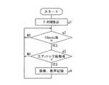
図35は、エアバッグが起動したとき、画像および音声をCFカード11に記録する処理を表すフローチャートである。アクセサリー電源から供給されるACC信号がオンとなる条件で、本フローが開始する。開始後ステップg1において、第1CPU13は、第1ROM14のプログラム等を読込み、次にステップg2に移行する。実際にはそのプログラムに沿って第1CPU13が動作する。ここで第1CPU13は、トリガ監視周期が10msec毎か否か、すなわち監視タイミングになったか否かを判断する。「否」との判断でステップg2に戻る。10msec毎との判断で、ステップg3に移行し、第1CPU13は、エアバッグ起動が有りか否かを判断する。「否」との判断でステップg2に戻る。有りとの判断でステップg4に移行し、第1CPU13は、画像および音声をCFカード11に記録させる。その後ステップg2に戻る。また図示はしないが、Gセンサ27等のその他のトリガも予め定められたトリガ監視周期で監視される。  FIG. 35 is a flowchart showing processing for recording an image and sound on theCF card 11 when the airbag is activated. This flow starts under the condition that the ACC signal supplied from the accessory power supply is turned on. In step g1 after the start, thefirst CPU 13 reads the program in thefirst ROM 14 and then proceeds to step g2. Actually, thefirst CPU 13 operates in accordance with the program. Here, thefirst CPU 13 determines whether or not the trigger monitoring period is every 10 msec, that is, whether or not the monitoring timing has come. If the determination is “NO”, the process returns to step g2. When it is determined every 10 msec, the process proceeds to step g3, and thefirst CPU 13 determines whether or not the airbag is activated. If the determination is “NO”, the process returns to step g2. If it is determined that there is, thefirst CPU 13 causes theCF card 11 to record an image and a sound. Thereafter, the process returns to step g2. Although not shown, other triggers such as theG sensor 27 are also monitored at a predetermined trigger monitoring cycle.

図36は、セキュリティECU55との接続例(1)を表すブロックである。セキュリティの場合には、ドアロックかつIGオフで監視モードに移行する。ドアがロック状態か否かは、ドアロック/アンロック検知スイッチ60により判断する。車両状態検出手段であるセキュリティECU55は、監視モードにおいてガラス割れや車内侵入がセンサ58、59により検知されると、ブザー56を鳴らすようにオン信号を出力する。本実施形態に係るドライブレコーダ1は、前記オン信号を外部入力として取り込めば、セキュリティ作動時に画像(車内外の画像)と音声とをCFカード11に記録する。セキュリティでは、IGオフ時に監視モードに移行するので、ドライブレコーダ1には、セキュリティECU55からドライブレコーダ1にIGオフでも起動信号を出力してドライブレコーダ1を起動させておく。FIG. 36 is a blockdiagram illustrating a connection example (1) with thesecurity ECU 55. In the case of security, it shifts to the monitoring mode when the door is locked and the IG is off. Whether or not the door is locked is determined by the door lock /unlock detection switch 60. Thesecurity ECU 55, which is a vehicle state detection means, outputs an ON signal to sound thebuzzer 56 when a glass break or intrusion in the vehicle is detected by thesensors 58 and 59 in the monitoring mode. Thedrive recorder 1 according to the present embodiment records images (images inside and outside the vehicle) and sound on theCF card 11 during security operation when the ON signal is captured as an external input. In security, since the mode shifts to the monitoring mode when the IG is off, thedrive recorder 1 is activated by outputting a start signal from thesecurity ECU 55 to thedrive recorder 1 even when the IG is off.

セキュリティの場合には、トリガの監視周期は100msecであるが、IGオフ時の監視するポートは外部入力スイッチだけでGセンサ27および制御装置2等の他のポートをみる必要がない。車両は停止しており、監視する必要がないからである。したがって第1CPU13の処理負荷を軽減して、電力消費の低減を図ることができる。セキュリティECU55を新たに接続する方法は、エアバッグECU53の場合と同様であるので省略する。  In the case of security, the monitoring period of the trigger is 100 msec, but the port to be monitored when the IG is off is only an external input switch, and it is not necessary to look at other ports such as theG sensor 27 and thecontrol device 2. This is because the vehicle is stopped and does not need to be monitored. Therefore, the processing load on thefirst CPU 13 can be reduced and the power consumption can be reduced. Since the method for newly connecting thesecurity ECU 55 is the same as that for theairbag ECU 53, a description thereof will be omitted.

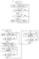
図37は、外部入力SWだけを監視する処理を表すフローチャートである。セキュリティECU55からドライブレコーダ1に起動信号を出力してドライブレコーダ1を起動させておく条件(ACC ON)で本処理が開始する。開始後ステップh1に移行して、第1CPU13は、第1ROM14の内容等を読込み、次にステップh2に移行する。ここで第1CPU13は、IGがオンが否かを判断する。「否」、すなわちIGオフで車両運転停止との判断でステップh3に移行し、IGがオンとの判断でステップh4に移行する。ステップh4において、第1CPU13は、通常のトリガ入力があるとCFカード11に記録させる処理を実行する。  FIG. 37 is a flowchart showing a process for monitoring only the external input SW. This process starts under the condition (ACC ON) for starting thedrive recorder 1 by outputting a start signal from thesecurity ECU 55 to thedrive recorder 1. After the start, the process proceeds to step h1, and thefirst CPU 13 reads the contents of thefirst ROM 14 and then proceeds to step h2. Here, thefirst CPU 13 determines whether or not the IG is on. If the determination is “NO”, that is, if the vehicle operation is stopped when IG is OFF, the process proceeds to step h3, and if it is determined that IG is ON, the process proceeds to step h4. In step h <b> 4, thefirst CPU 13 executes a process of recording on theCF card 11 when there is a normal trigger input.

ステップh3では、第1CPU13は、トリガの周期が100msec毎か否か、すなわち監視タイミングか否かを判断する。「否」との判断でステップh2に戻る。100msec毎との判断でステップh5に移行し、第1CPU13は、セキュリティ起動が有るか(警報信号があるか)否かを判断する。「否」との判断でステップh2に戻る。セキュリティ起動有りとの判断でステップh6に移行し、第1CPU13は画像および音声をCFカード11に記録させる。その後ステップh2に戻る。したがってIGオフ時は、ステップh4には進まず、その他のトリガの監視が無視される。  In step h3, thefirst CPU 13 determines whether or not the trigger cycle is every 100 msec, that is, whether or not it is a monitoring timing. When the determination is “NO”, the process returns to step h2. If it is determined every 100 msec, the process proceeds to step h5, and thefirst CPU 13 determines whether there is a security activation (there is an alarm signal). When the determination is “NO”, the process returns to step h2. When it is determined that the security is activated, the process proceeds to step h6, and thefirst CPU 13 records the image and sound on theCF card 11. Thereafter, the process returns to step h2. Therefore, when the IG is off, the process does not proceed to step h4, and monitoring of other triggers is ignored.

図38は、複数機器との接続例を表すブロックである。ドライブレコーダ1のシリアル通信ポート51を適用すれば、トリガ入力だけでなく、情報の入出力が可能となる。たとえばエアバッグからのトリガがあった場合、エアバッグECU53からの衝撃度およびオーディオ・ナビゲーションシステム57からの交通情報(渋滞情報など)を取込み、ドライブレコーダ1がこれらをCFカード11に記録することで、事故分析をより詳細に行える。FIG. 38 is a blockdiagram illustrating a connection example with a plurality of devices. If theserial communication port 51 of thedrive recorder 1 is applied, not only trigger input but also information input / output becomes possible. For example, when there is a trigger from an airbag, the impact degree from theairbag ECU 53 and traffic information (such as traffic jam information) from theaudio navigation system 57 are taken in, and thedrive recorder 1 records them on theCF card 11. , More detailed accident analysis.

以上説明したドライブレコーダ1によれば、オンオフポート52がエアバッECU53またはセキュリティECU55などからの信号を入力すると、第1CPU13は入力された信号をトリガとしてCFカード11に記録するよう制御する。特にオンオフポート52は、車両3が所定の状態になったことを検出する検出手段とは異なる別の車両状態検出手段からの信号を入力可能になっているので、最初からドライブレコーダを製造し直す必要がなく、その分コスト低減を図ることができる。したがってトリガが追加要求されても、簡単に追加できる汎用性の高いドライブレコーダを提供することができる。According to thedrive recorder 1 described above, the on-off port 52 for inputting a signal from suchairbags ECU53 orsecurity ECU 55, the 1CPU13 controls to record theCF card 11 the input signal as a trigger. In particular, the on / offport 52 can input a signal from another vehicle state detection means different from the detection means for detecting that thevehicle 3 is in a predetermined state, so that the drive recorder is manufactured again from the beginning. There is no need, and the cost can be reduced accordingly. Therefore, it is possible to provide a versatile drive recorder that can be easily added even when an additional trigger is requested.

エアバッグを展開させることを示す信号があるか否かを監視するタイミングを、予め設定されている監視タイミングより早く設定可能であるので、トリガの内容に応じてトリガの監視周期を適切に変更することができる。車両運転停止時に警報を行わせる信号があるか否かの監視を行ない、車両運転停止時に不要なその他のトリガの監視を無視するので、車両状態に応じて監視トリガの内容を限定することができる。したがって第1CPU13の処理負荷を低減することができる。  Since the timing for monitoring whether or not there is a signal indicating that the airbag is to be deployed can be set earlier than the preset monitoring timing, the trigger monitoring cycle is appropriately changed according to the trigger content be able to. Since it is monitored whether or not there is a signal for giving an alarm when the vehicle is stopped and monitoring of other unnecessary triggers is ignored when the vehicle is stopped, the contents of the monitor trigger can be limited according to the vehicle state. . Therefore, the processing load on thefirst CPU 13 can be reduced.

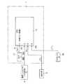
図39は、本発明の実施形態に係り、セキュリティECU55とドライブレコーダ1との接続例(2)を表すブロック図である。本実施形態に係る説明は、運転情報記録方法の説明をも含む。図8も参照しつつ説明する。セキュリティECU55は、車両のガラス割れなどを検知するガラス割れセンサ58、車両への侵入を電波や超音波により検知する侵入センサ59、ドアの開閉状態を検出するドアカーテシスイッチ66、車両バッテリ(図においてBATTと表記)、イグニッションスイッチ(図においてIG SWと表記)などと電気的に接続されている。セキュリティECU55は、送信機RSからロックまたはアンロック要求信号を受け、車両ドアをロック状態とアンロック(非ロック)状態とにわたって切換えるように制御する。セキュリティECU55は、ブザー56を鳴らす信号を出力するため該ブザー56と電気的に接続され、さらにドアロック機構を駆動する(つまりロックする)駆動源61と電気的に接続されている。ドライブレコーダ1には、セキュリティECU55から前記駆動源61へのいわゆるロック信号を外部入力として取り込むポート62等が予め設けられている。  FIG. 39 is a block diagram illustrating a connection example (2) between thesecurity ECU 55 and thedrive recorder 1 according to the embodiment of the present invention. The description according to the present embodiment also includes the description of the driving information recording method. This will be described with reference to FIG. Thesecurity ECU 55 includes aglass break sensor 58 that detects glass breakage of the vehicle, anintrusion sensor 59 that detects intrusion into the vehicle by radio waves and ultrasonic waves, adoor courtesy switch 66 that detects the open / closed state of the door, a vehicle battery (BATT in the figure). And an ignition switch (denoted as IG SW in the figure) and the like. Thesecurity ECU 55 receives a lock or unlock request signal from the transmitter RS, and controls the vehicle door to be switched between a locked state and an unlocked (unlocked) state. Thesecurity ECU 55 is electrically connected to thebuzzer 56 in order to output a signal for sounding thebuzzer 56, and further electrically connected to adrive source 61 that drives (that is, locks) the door lock mechanism. Thedrive recorder 1 is previously provided with aport 62 and the like for taking in a so-called lock signal from thesecurity ECU 55 to thedrive source 61 as an external input.

セキュリティECU55は、送信機RSからIDコード(ID:Identification)とともにロック要求信号を受信すると、セキュリティECU55自身に予め記憶されているIDコードと受信したIDコードとを比較し、両者が一致した場合、駆動源61にロック信号を出力してドアをロックするとともに、盗難監視モードに移行する。盗難監視モードでは、ガラス割れセンサ58、侵入センサ59、ドアカーテシスイッチ66により盗難が発生したか否かを判断する。盗難の発生を検出すると警報モードに移行し、セキュリティECU55はブザー56を鳴動すべくアラーム信号を出力する。  When thesecurity ECU 55 receives the lock request signal together with the ID code (ID: Identification) from the transmitter RS, thesecurity ECU 55 compares the ID code stored in advance in thesecurity ECU 55 with the received ID code. A lock signal is output to thedrive source 61 to lock the door and shift to the theft monitoring mode. In the theft monitoring mode, theglass break sensor 58, theintrusion sensor 59, and thedoor courtesy switch 66 determine whether the theft has occurred. When the theft occurrence is detected, the mode is shifted to the alarm mode, and thesecurity ECU 55 outputs an alarm signal to sound thebuzzer 56.

ドライブレコーダ1はたとえば前記ロック信号によっても起動するように構成される。そのため、ロック信号は図13のOR回路47に他の入力(ACCなど)とともに入力されている。つまりOR回路47の入力側に、ACC信号、パワーオン信号や本実施形態に係るロック信号がそれぞれ供給可能に構成される。当該ドライブレコーダ1の第1CPU13は、前記ロック信号でドライブレコーダ1が起動した状態においてアラーム信号があるか否かを監視するように構成されている。第1CPU13は、アラーム信号ありと判断すると、該アラーム信号をトリガとして第2のSD−RAM30に巡回的に記憶された画像、音声などを、トリガ発生前後にわたって、書換え可能なフラッシュROMである第1ROM14に記録するよう制御する。第1ROM14が、運転情報記録装置内部の記憶媒体に相当する。  Thedrive recorder 1 is configured to be activated by the lock signal, for example. For this reason, the lock signal is input to theOR circuit 47 of FIG. 13 together with other inputs (such as ACC). That is, the ACC signal, the power-on signal, and the lock signal according to the present embodiment can be supplied to the input side of theOR circuit 47, respectively. Thefirst CPU 13 of thedrive recorder 1 is configured to monitor whether there is an alarm signal when thedrive recorder 1 is activated by the lock signal. When thefirst CPU 13 determines that there is an alarm signal, thefirst ROM 14 is a flash ROM that can rewrite images, sounds, and the like stored cyclically in the second SD-RAM 30 using the alarm signal as a trigger before and after the occurrence of the trigger. Control to record. Thefirst ROM 14 corresponds to a storage medium inside the driving information recording device.

図40は、ロック信号などに基づき、画像などを第1ROM14に記録する処理を表すフローチャートである。ACCなどまたはロック信号等によるドライブレコーダ本体5の電源投入で本処理が開始する。本処理開始後ステップi1に移行し、第1CPU13は電源制御信号S2を出力する(図13参照)。次にステップi2に移行し、運転中か否かを区別するため、第1CPU13はIGがオンか否かを判断する。  FIG. 40 is a flowchart showing processing for recording an image or the like in thefirst ROM 14 based on a lock signal or the like. This process starts when the power of the drive recordermain body 5 is turned on by ACC or the like or a lock signal or the like. After the start of this process, the process proceeds to step i1, and thefirst CPU 13 outputs a power control signal S2 (see FIG. 13). Next, the process proceeds to step i2, and thefirst CPU 13 determines whether or not the IG is on in order to distinguish whether or not the vehicle is in operation.

ここでIGオンつまり運転中との判断でステップi3に移行する。運転中ではないとの判断でステップi4aに移行する。本ステップi4aにおいて、第1CPU13は、図12に示す通常制御か否か区別するため、ロック信号を外部入力として取り込んだか否かを判断する。「否」との判断でステップi7に移行し、ACC信号がオフになってもドライブレコーダ1がデータ記録できるように、第1CPU13は、ACC信号オフ(図41、PL1)後、T1秒経過後に電源制御信号S2をオフにするように制御する(つまり図12に示す通常制御を実行する)。その後ステップi2に戻る。  If IG is turned on, that is, it is determined that the vehicle is operating, the process proceeds to step i3. If it is determined that the vehicle is not in operation, the process proceeds to step i4a. In step i4a, thefirst CPU 13 determines whether or not the lock signal is taken in as an external input in order to distinguish whether or not the normal control shown in FIG. If the determination is “NO”, the process proceeds to step i7, and thefirst CPU 13 waits for T1 seconds after the ACC signal is turned off (PL1 in FIG. 41) so that thedrive recorder 1 can record data even if the ACC signal is turned off. Control is performed to turn off the power supply control signal S2 (that is, normal control shown in FIG. 12 is executed). Thereafter, the process returns to step i2.

ステップi4aにおいて、第1CPU13は、セキュリティECU55から前記駆動源61へのロック信号を外部入力として取り込むとセキュリティセットと判断し、次にステップi8に移行し、定期的にセキュリティ起動すなわちアラーム信号出力の有無を判断するため、第1CPU13はたとえば「100msec」毎か否かを判断する。ただし必ずしも100msec毎に限定されるものではない。「否」との判断でステップi2に戻る。  In step i4a, thefirst CPU 13 determines that it is a security set when it receives a lock signal from thesecurity ECU 55 to thedrive source 61 as an external input, and then proceeds to step i8 to periodically perform security activation, that is, whether an alarm signal is output. For example, thefirst CPU 13 determines whether or not every “100 msec”. However, it is not necessarily limited to every 100 msec. If the determination is “NO”, the process returns to step i2.

100msec毎であるとの判断でステップi9に移行し、画像、音声などを記録するトリガとして、第1CPU13はアラーム信号の有無を判断する。アラーム信号出力なしとの判断で、ステップi2に戻る。アラーム信号出力あり、すなわち盗難発生との判断で、ステップi10に移行する。該ステップにおいて、第1CPU13は、第2のSD−RAM30に記憶されたたとえば画像、音声などの運転情報を第1ROM14に記録させる処理を実行する。その後ステップi2に戻る。盗難発生時に運転情報をCFカード11ではなく第1ROM14に記録することで、記録媒体が泥棒によって持ち去られることを防止できる。  If it is determined every 100 msec, the process proceeds to step i9, where thefirst CPU 13 determines the presence or absence of an alarm signal as a trigger for recording images, sounds, and the like. If it is determined that no alarm signal is output, the process returns to step i2. If there is an alarm signal output, that is, it is determined that theft has occurred, the process proceeds to step i10. In this step, thefirst CPU 13 executes a process for causing thefirst ROM 14 to record driving information such as images and sounds stored in the second SD-RAM 30. Thereafter, the process returns to step i2. By recording the operation information in thefirst ROM 14 instead of theCF card 11 when a theft occurs, the recording medium can be prevented from being taken away by a thief.

ステップi2でIGオンつまり運転中との判断で、第1CPU13は、車両運転中における通常の記録処理を行う。すなわち、トリガ入力があると第2のSD−RAM30に記憶されたたとえば画像などの運転情報をCFカード11に記録させる処理を実行する。次にステップi5に移行し、第1CPU13は、第1ROM14に記録した運転情報の出力指示の有無を判断する。出力指示なしの判断でステップi2に戻る。出力指示ありとの判断でステップi6に移行し、ステップi10で第1ROM14に記録した運転情報すなわちセキュリティの記録をCFカード11に記録させる処理を実行する。  If it is determined in step i2 that IG is on, that is, during driving, thefirst CPU 13 performs normal recording processing during driving of the vehicle. That is, when there is a trigger input, a process for recording driving information such as an image stored in the second SD-RAM 30 on theCF card 11 is executed. Next, the process proceeds to step i5, and thefirst CPU 13 determines whether or not there is an instruction to output the driving information recorded in thefirst ROM 14. If there is no output instruction, the process returns to step i2. If it is determined that there is an output instruction, the process proceeds to step i6, and the operation information recorded in thefirst ROM 14, that is, the security record, is recorded in theCF card 11 in step i10.

図41はタイミングチャートを表し、図41(a)は、ACC信号オフ(PL1)後、T1秒経過後に電源制御信号S2がオフとなった状態で、第1CPU13はロック信号ありと判断した形態を表すタイミングチャート、図41(b)は、ACC信号オフ(PL1)後T1秒経過前に、第1CPU13はロック信号ありと判断した形態を表すタイミングチャートである。  FIG. 41 shows a timing chart. FIG. 41A shows a state in which thefirst CPU 13 determines that there is a lock signal in a state where the power control signal S2 is turned off after T1 seconds have elapsed after the ACC signal is turned off (PL1). A timing chart shown in FIG. 41B is a timing chart showing a form in which thefirst CPU 13 determines that there is a lock signal before the lapse of T1 seconds after the ACC signal is turned off (PL1).

図41(a),(b)に示すように、第1CPU13は、ACC信号オフ(PL1)を起算時として計時する。ACC信号オフ時点で電源制御信号S2はオン状態を維持する。図41(b)に示すように、第1CPU13は、ACC信号オフ(PL1)後T1秒経過前にロック信号あり(つまりセキュリティセット)と判断すると、電源制御信号S2のオン状態を維持する。図41(a)に示すように、第1CPU13は、ACC信号オフ(PL1)後T1秒経過後、電源制御信号S2をオン状態からオフにする。その後第1CPU13は、ロック信号があるつまりセキュリティセットされると、電源制御信号S2をオンにする。  As shown in FIGS. 41A and 41B, thefirst CPU 13 counts the time when the ACC signal is off (PL1). When the ACC signal is off, the power supply control signal S2 is kept on. As shown in FIG. 41 (b), when thefirst CPU 13 determines that there is a lock signal (that is, a security set) before the lapse of T1 seconds after the ACC signal is turned off (PL1), thefirst CPU 13 maintains the on state of the power control signal S2. As shown in FIG. 41A, thefirst CPU 13 turns off the power supply control signal S2 from the on state after T1 seconds have elapsed after the ACC signal is turned off (PL1). Thereafter, when there is a lock signal, that is, when security is set, thefirst CPU 13 turns on the power control signal S2.

以上説明したセキュリティECU55とドライブレコーダとの接続例(2)によれば、セキュリティECUが出力するロック信号によってドライブレコーダ1が起動する、換言すれば専用信号ではなく、元々の盗難監視状態になったことを表す信号を用いてドライブレコーダ1を起動することができる。図40のステップi4aに示すように、第1CPU13は、セキュリティECU55から駆動源61へのロック信号を外部入力として取り込むとセキュリティセットされたと判断する(ステップi4a:YES)。したがって前記専用信号を用いるものに比べて、(セキュリティECU55など一切改造することなく)ドライブレコーダ1の配線接続を簡単化でき、部品点数の低減および工数の低減を図ることができる。  According to the connection example (2) between thesecurity ECU 55 and the drive recorder described above, thedrive recorder 1 is activated by the lock signal output from the security ECU, in other words, not the dedicated signal but the original theft monitoring state. Thedrive recorder 1 can be activated using a signal indicating this. As shown in step i4a of FIG. 40, thefirst CPU 13 determines that the security is set when the lock signal from thesecurity ECU 55 to thedrive source 61 is taken as an external input (step i4a: YES). Therefore, the wiring connection of thedrive recorder 1 can be simplified (without modifying thesecurity ECU 55 or the like), and the number of parts and the number of man-hours can be reduced as compared with those using the dedicated signal.

セキュリティセットされた後(ステップi4a:YES)、微小時間毎(たとえば100msec毎)にアラーム信号出力の有無を判断するので、セキュリティ性を高めることができる。図40のステップi10において、ドライブレコーダ内部の第1ROM14に記録したセキュリティの記録を、ステップi6においてCFカード11に記録させるので、センタ機器または各種機関などにCFカード11を容易にかつ確実に提供することができる。  After the security is set (step i4a: YES), the presence or absence of the alarm signal output is determined every minute time (for example, every 100 msec), so that the security can be improved. In step i10 in FIG. 40, the security record recorded in thefirst ROM 14 inside the drive recorder is recorded in theCF card 11 in step i6, so that theCF card 11 can be easily and reliably provided to a center device or various institutions. be able to.

第1ROM14に記録した運転情報を、ACC信号オンからオフ後、たとえば一定時間(T2秒=15秒)以内に撮影スイッチ9を長押し(たとえば4秒以上15秒以下)するなどの操作によって、CFカード11に複写または移動することも可能である。その後CFカード11に記録された運転情報をセンタなどにおいて容易にかつ迅速に解析することができる。つまりドライブレコーダ1を車両から取り外すことなく、運転情報を容易にかつ迅速に解析でき、利便性を高めることが可能となる。  After the operation information recorded in thefirst ROM 14 is turned off after the ACC signal is turned on, for example, by pressing and holding theshooting switch 9 within a certain time (T2 seconds = 15 seconds) (for example, 4 seconds to 15 seconds), the CF It is also possible to copy or move to thecard 11. Thereafter, the operation information recorded on theCF card 11 can be easily and quickly analyzed at the center or the like. That is, driving information can be analyzed easily and quickly without removing thedrive recorder 1 from the vehicle, and convenience can be improved.

車両に設けられるバッテリとは異なる二次電池BATT2(図39参照)をドライブレコーダ内部に設け、IGオフでかつセキュリティが起動したときは、該二次電池BATT2によってドライブレコーダ1の起動状態を継続する構成にしてもよい。または第1CPU13は、前記バッテリが予め定める電圧値(たとえば10V以下)になったと判断すると、ドライブレコーダ1の電源を車両付属のバッテリから二次電池BATT2に切換える制御を行うようにしてもよい。このような構成によれば、ドライブレコーダ1の起動状態を継続する確実性を高めることができる。  A secondary battery BATT2 (see FIG. 39) different from the battery provided in the vehicle is provided inside the drive recorder, and when the IG is off and the security is activated, the activated state of thedrive recorder 1 is continued by the secondary battery BATT2. It may be configured. Alternatively, when thefirst CPU 13 determines that the battery has reached a predetermined voltage value (for example, 10 V or less), thefirst CPU 13 may perform control to switch the power source of thedrive recorder 1 from the battery attached to the vehicle to the secondary battery BATT2. According to such a configuration, it is possible to improve the certainty of continuing the activated state of thedrive recorder 1.

図42は、本発明の実施形態に係り、セキュリティECU55とドライブレコーダ1との接続例(3)を表すブロック図である。前述の図39に示す接続例(2)では、ドライブレコーダは、セキュリティECU55から出力されるロック信号を外部入力として取り込んでいるが、本実施形態に係る接続例(3)では、ドライブレコーダ1は、セキュリティECU55から、盗難監視モードの間たとえば車両のダッシュボードなどに設けられる発光ダイオード63(略称LED:Light Emitting Diode)に出力される監視信号を外部入力として取り込む。  FIG. 42 is a block diagram illustrating a connection example (3) between thesecurity ECU 55 and thedrive recorder 1 according to the embodiment of the present invention. In the connection example (2) shown in FIG. 39 described above, the drive recorder takes in the lock signal output from thesecurity ECU 55 as an external input. However, in the connection example (3) according to the present embodiment, thedrive recorder 1 Thesecurity ECU 55 captures, as an external input, a monitoring signal output to a light emitting diode 63 (abbreviated as LED: Light Emitting Diode) provided, for example, on the dashboard of the vehicle during the theft monitoring mode.

本実施形態に係るドライブレコーダ1には、前記監視信号を外部入力として取り込むポート64が予め設けられている。ドライブレコーダ1はたとえば前記監視信号によって起動するように構成され、当該ドライブレコーダ1の第1CPU13は、前記監視信号でドライブレコーダ1が起動した状態においてアラーム信号があるか否かを監視するように構成されている。本実施形態に係る接続例(3)においても、前記専用信号を用いるものに比べて、ドライブレコーダ1の配線接続を簡単化でき、部品点数の低減および工数の低減を図ることができる。  Thedrive recorder 1 according to the present embodiment is provided with aport 64 that takes in the monitoring signal as an external input in advance. Thedrive recorder 1 is configured to be activated by, for example, the monitoring signal, and thefirst CPU 13 of thedrive recorder 1 is configured to monitor whether or not there is an alarm signal when thedrive recorder 1 is activated by the monitoring signal. Has been. Also in the connection example (3) according to the present embodiment, the wiring connection of thedrive recorder 1 can be simplified and the number of parts and the number of man-hours can be reduced as compared with the connection example using the dedicated signal.

前述の図39に示した接続例(2)では、図40のステップi4aにおいて、第1CPU13がロック信号を外部入力として取り込んだか否かを判断していた。これに対して図42に示す本接続例(3)では、図40のステップi4aにおいて、第1CPU13が前記監視信号を外部入力として取り込んだか否かを判断している。「否」との判断でステップi7に移行する。前記監視信号を取り込むと、次にステップi8に移行する。本接続例(3)のフローチャートでは、ステップi4a以外、図40のフローチャートと同一の開始条件でかつ、同一ステップとなっている。  In the connection example (2) shown in FIG. 39 described above, in step i4a of FIG. 40, thefirst CPU 13 determines whether or not the lock signal is taken as an external input. On the other hand, in this connection example (3) shown in FIG. 42, in step i4a of FIG. 40, thefirst CPU 13 determines whether or not the monitoring signal is taken as an external input. If it is determined as “NO”, the process proceeds to step i7. When the monitoring signal is captured, the process proceeds to step i8. In the flowchart of this connection example (3), except for step i4a, the same start conditions and the same steps as those in the flowchart of FIG.

第1CPU13は、前記監視信号およびロック信号の少なくともいずれか一つを外部入力として取り込んだか否かを判断してもよい。この場合には、LED63への配線が断線した場合においても、接続例(2)と同様にステップi4aにおいて第1CPU13はロック信号を外部入力として取り込んだか否かを判断することが可能となる。したがって監視信号だけを外部入力として取り込む形態よりもセキュリティ性を一層高めることができる。  Thefirst CPU 13 may determine whether at least one of the monitoring signal and the lock signal is taken as an external input. In this case, even when the wiring to theLED 63 is disconnected, thefirst CPU 13 can determine whether or not the lock signal has been taken in as an external input in step i4a as in the connection example (2). Therefore, the security can be further improved as compared with a mode in which only the monitoring signal is taken as an external input.

図43は、本発明の実施形態に係り、セキュリティECU55とドライブレコーダとの接続例(4)を表すブロック図である。本実施形態に係る接続例(4)のドライブレコーダ1には、セキュリティECU55が電気的接続されるか否かを設定する設定スイッチ65が設けられている。  FIG. 43 is a block diagram illustrating a connection example (4) between thesecurity ECU 55 and the drive recorder according to the embodiment of the present invention. Thedrive recorder 1 of the connection example (4) according to the present embodiment is provided with a settingswitch 65 for setting whether or not thesecurity ECU 55 is electrically connected.

図44は、設定スイッチ65などに基づき、画像などを第1ROM14に記録する処理を表すフローチャートである。本処理の開始条件は、ACC信号などによるドライブレコーダ本体5の電源投入である。本フローチャートにおいて、図40で説明したフローチャートと同一のステップについては同一のステップ番号を付し、その説明を省略する。ステップi2で運転中ではないとの判断で、ステップi4bに移行し、第1CPU13は設定スイッチ65に基づきセキュリティECU55が電気的に接続されるか否かを判断している。  FIG. 44 is a flowchart showing processing for recording an image or the like in thefirst ROM 14 based on the settingswitch 65 or the like. The starting condition of this process is to turn on the power of thedrive recorder body 5 by an ACC signal or the like. In this flowchart, the same steps as those in the flowchart described in FIG. 40 are denoted by the same step numbers, and the description thereof is omitted. If it is determined in step i2 that the vehicle is not operating, the process proceeds to step i4b, and thefirst CPU 13 determines whether or not thesecurity ECU 55 is electrically connected based on the settingswitch 65.

具体的にステップi4bにおいて、第1CPU13は、セキュリティECU55と電気的に接続されていないと判断すると(ステップi4b:NO)、ステップi7に移行し、第1CPU13は、ACC信号オフ後、T1秒経過後に電源制御信号S2をオフにするように制御する、つまり図12に示す通常制御を実行する。ステップi4bにおいて、第1CPU13は、セキュリティECU55と電気的に接続されていると判断すると(ステップi4b:YES)、ステップi8に移行する。  Specifically, in step i4b, if thefirst CPU 13 determines that it is not electrically connected to the security ECU 55 (step i4b: NO), the process proceeds to step i7, and thefirst CPU 13 waits for T1 seconds after the ACC signal is turned off. Control is performed to turn off the power supply control signal S2, that is, normal control shown in FIG. 12 is executed. In step i4b, when determining that thefirst CPU 13 is electrically connected to the security ECU 55 (step i4b: YES), thefirst CPU 13 proceeds to step i8.

以上説明した接続例(4)によれば、セキュリティECU55との電気的接続を自由にかつ簡単に選択できるシステムを実現できる。このように汎用性の高いドライブレコーダを実現できる。前記設定スイッチ65をたとえば撮影スイッチ9などと兼用することも可能である。たとえばメンテナンスモードにおいて、撮影スイッチ9を設定スイッチに切換えてもよい。この場合には、ドライブレコーダの部品点数の低減を図り、製造コストを低減することができる。ドライブレコーダ1において、CFカード11に記録された設定プログラムに基づいて、セキュリティECU55との電気的接続を維持するか解消するかを設定してもよい。センタ機器を用いて、CFカード11に前記設定プログラムを記録することができる。ドライブレコーダ本体5のたとえば第1ROM14に、前記設定プログラムを予め記録させておくことも可能である。このような構成によっても、セキュリティECU55との電気的接続を自由にかつ簡単に選択できるシステムを実現できる。  According to the connection example (4) described above, it is possible to realize a system that can freely and easily select an electrical connection with thesecurity ECU 55. Thus, a highly versatile drive recorder can be realized. For example, the settingswitch 65 can also be used as the photographingswitch 9 or the like. For example, the photographingswitch 9 may be switched to the setting switch in the maintenance mode. In this case, the number of parts of the drive recorder can be reduced and the manufacturing cost can be reduced. In thedrive recorder 1, whether to maintain or cancel the electrical connection with thesecurity ECU 55 may be set based on the setting program recorded in theCF card 11. The setting program can be recorded on theCF card 11 using the center device. For example, the setting program can be recorded in advance in thefirst ROM 14 of the drive recordermain body 5. Even with such a configuration, it is possible to realize a system capable of freely and easily selecting an electrical connection with thesecurity ECU 55.

本発明の第1の実施形態に係るドライブレコーダ1と制御装置2との関係を表す斜視図である。It is a perspective view showing the relationship between thedrive recorder 1 and thecontrol apparatus 2 which concern on the 1st Embodiment of this invention.ドライブレコーダ1を部分的に変更した変更形態の斜視図である。It is the perspective view of the modified form which changed thedrive recorder 1 partially.車両3へのカメラ取付け位置を説明するための図である。FIG. 4 is a diagram for explaining a camera mounting position on avehicle 3.センタ4を表す図であり、図4(a)はセンタ機器構成を表す図であり、図4(b)は、ディスプレイ4aに車両3の走行軌跡、撮像画像およびGセンサ計測値を出力した一態様を表す図である。4A is a diagram showing thecenter 4, FIG. 4A is a diagram showing the center device configuration, and FIG. 4B is a diagram in which a traveling locus, a captured image, and a G sensor measurement value of thevehicle 3 are output to thedisplay 4a. It is a figure showing an aspect.ドライブレコーダ1の斜視図である。1 is a perspective view of adrive recorder 1. FIG.ドライブレコーダ1の正面図である。1 is a front view of adrive recorder 1. FIG.ドライブレコーダ1、制御装置2およびセンタ4の電気的構成を表すブロック図である。2 is a block diagram showing an electrical configuration of adrive recorder 1, acontrol device 2, and acenter 4. FIG.ドライブレコーダ1の電気的構成を表すブロック図である。2 is a block diagram showing an electrical configuration of thedrive recorder 1. FIG.制御装置2の電気的構成を表すブロック図である。3 is a block diagram illustrating an electrical configuration of acontrol device 2. FIG.制御装置2の要部の電気的構成を表すブロック図である。3 is a block diagram illustrating an electrical configuration of a main part of thecontrol device 2. FIG.ドライブレコーダ1の要部の電気的構成を表すブロック図である。2 is a block diagram illustrating an electrical configuration of a main part of thedrive recorder 1. FIG.ウォッチドッグパルスが停止または規定の周期で動作しない場合、ハードウェアによりリセットをかける遅延回路を説明する図である。It is a figure explaining the delay circuit which resets by hardware, when a watchdog pulse stops or does not operate | work with a regular period.ドライブレコーダ1を部分的に変更した変更形態に係る、要部の電気的構成を表すブロック図である。It is a block diagram showing the electric constitution of the principal part concerning the modification which changeddrive recorder 1 partially.画像情報の一部と位置情報等との関係を表す図である。It is a figure showing the relationship between a part of image information, position information, etc.Gセンサ出力値に基づいて、静止画像情報が一定間隔δおきにCFカード11に記録される態様を表す図である。It is a figure showing the aspect by which still image information is recorded on theCF card 11 at fixed intervals (delta) based on G sensor output value.閾値を超過したGセンサ出力値48と、CFカード11に記録される画像情報の記録範囲Rhとの関係を表す図である。6 is a diagram illustrating a relationship between a Gsensor output value 48 that exceeds a threshold and a recording range Rh of image information recorded on theCF card 11. FIG.Gセンサ出力値の閾値判定方法を説明するための図である。It is a figure for demonstrating the threshold value determination method of G sensor output value.撮影スイッチ9のオン信号S3と、CFカード11に記録される画像情報の記録範囲Rhとの関係を表す図である。6 is a diagram illustrating a relationship between an ON signal S3 of the photographingswitch 9 and a recording range Rh of image information recorded on theCF card 11. FIG.通信による撮影要求コマンド受信と、CFカード11に記録される画像情報の記録範囲Rhとの関係を表す図である。6 is a diagram illustrating a relationship between reception of a shooting request command by communication and a recording range Rh of image information recorded on theCF card 11.実車/空車メータ44からのHi/Lo信号S4に基づいて、CFカード11に記録される音声情報の記録範囲が規定される態様を表す図である。It is a figure showing the aspect by which the recording range of the audio | voice information recorded on theCF card 11 is prescribed | regulated based on the Hi / Lo signal S4 from the actual vehicle / empty vehicle meter.

実車/空車メータ44からのHi信号が出力される時点の前後にわたって画像情報が記録され、Lo信号が出力される時点の前後にわたって画像情報が記録される態様を表す図である。It is a figure showing the aspect by which image information is recorded before and after the time of outputting the Hi signal from the actual vehicle /empty vehicle meter 44, and before and after the time of outputting the Lo signal.ドライブレコーダ1において、トリガの各種とりこみについて説明するブロック図である。It is a block diagram explaining the various acquisition of a trigger in the drive recorder.運行データの閾値に基づいて警告情報を発する態様を表す図である。It is a figure showing the aspect which emits warning information based on the threshold value of operation data.Gセンサ出力値と検知時間との関係を表す図である。It is a figure showing the relationship between G sensor output value and detection time.Gセンサ出力値の大小とその検知時間との関係に基づく傾向を表す図表である。It is a chart showing the tendency based on the relationship between the magnitude of G sensor output value and its detection time.Gセンサと外部スイッチ検出による基本動作を表すフローチャートである。It is a flowchart showing the basic operation | movement by G sensor and external switch detection.Gセンサ出力の閾値とその判定時間との関係を表す図である。It is a figure showing the relationship between the threshold value of G sensor output, and its determination time.Hi/Lo信号とその判定時間との関係を表すタイミングチャートである。It is a timing chart showing the relationship between a Hi / Lo signal and its determination time.音声データを記録する処理を表すフローチャートであり、図29(a)は、実空車変化前後にわたって音声データを記録する処理を表すフローチャート、図29(b)は、実車中の音声データを記録する処理を表すフローチャートである。FIG. 29A is a flowchart showing a process for recording voice data, FIG. 29A is a flowchart showing a process for recording voice data before and after the actual empty vehicle change, and FIG. 29B is a process for recording voice data in the actual vehicle. It is a flowchart showing.制御装置で合成音声を出力する第1の処理を表すフローチャートである。It is a flowchart showing the 1st process which outputs a synthetic | combination voice with a control apparatus.制御装置で合成音声を出力する第2の処理を表すフローチャートである。It is a flowchart showing the 2nd process which outputs a synthetic | combination voice with a control apparatus.他機器接続用シリアルポート51などを含むドライブレコーダ1の電気的構成を表すブロック図である。2 is a block diagram showing an electrical configuration of adrive recorder 1 including aserial port 51 for connecting other devices and the like. FIG.エアバッECU53との接続例を表すブロックである。Is a blockdiagram showing an example of connection of theairbags ECU 53.トリガ監視周期などを変更する処理を表し、図34(a)はそのフローチャート、図34(b)は各種トリガに対応したトリガ周期を表すマップである。FIG. 34A shows a process for changing the trigger monitoring period and the like, and FIG. 34B is a map showing trigger periods corresponding to various triggers.エアバッグが起動したとき、画像および音声をCFカード11に記録する処理を表すフローチャートである。6 is a flowchart showing a process for recording an image and sound on theCF card 11 when the airbag is activated.セキュリティECU55との接続例(1)を表すブロックである。It is a blockdiagram showing the example of connection (1) with security ECU55.外部入力スイッチだけを監視する処理を表すフローチャートである。It is a flowchart showing the process which monitors only an external input switch.複数機器との接続例を表すブロックである。It is a blockdiagram showing the example of a connection with multiple apparatuses.本発明の実施形態に係り、セキュリティECU55とドライブレコーダ1との接続例(2)を表すブロック図である。FIG. 6 is a block diagram illustrating a connection example (2) between thesecurity ECU 55 and thedrive recorder 1 according to the embodiment of the present invention.ロック信号などに基づき、画像などを第1ROM14に記録する処理を表すフローチャートである。4 is a flowchart showing processing for recording an image or the like in thefirst ROM 14 based on a lock signal or the like.

タイミングチャートを表し、図41(a)は、ACC信号オフ(PL1)後、T1秒経過後に電源制御信号S2がオフとなった状態で、第1CPU13はロック信号ありと判断した形態を表すタイミングチャート、図41(b)は、ACC信号オフ(PL1)後T1秒経過前に、第1CPU13はロック信号ありと判断した形態を表すタイミングチャートである。41A shows a timing chart. FIG. 41A is a timing chart showing a mode in which thefirst CPU 13 determines that there is a lock signal in a state in which the power control signal S2 is turned off after T1 seconds have elapsed after the ACC signal is turned off (PL1). FIG. 41B is a timing chart showing a form in which thefirst CPU 13 determines that there is a lock signal before the lapse of T1 seconds after the ACC signal is turned off (PL1).本発明の実施形態に係り、セキュリティECU55とドライブレコーダ1との接続例(3)を表すブロック図である。FIG. 10 is a block diagram illustrating a connection example (3) between thesecurity ECU 55 and thedrive recorder 1 according to the embodiment of the present invention.本発明の実施形態に係り、セキュリティECU55とドライブレコーダ1との接続例(4)を表すブロック図である。FIG. 6 is a block diagram illustrating a connection example (4) between thesecurity ECU 55 and thedrive recorder 1 according to the embodiment of the present invention.設定スイッチ65などに基づき、画像などを第1ROM14に記録する処理を表すフローチャートである。4 is a flowchart showing a process for recording an image or the like in thefirst ROM 14 based on a settingswitch 65 or the like.

符号の説明Explanation of symbols

1 ドライブレコーダ
11 CFカード
12 第1RAM
13 第1CPU
14 第1ROM
52 オンオフポート
53 エアバッECU
55 セキュリティECU
65 設定スイッチ
1drive recorder 11CF card 12 first RAM
13 First CPU
14 First ROM
52 offport 53airbags ECU
55 Security ECU
65 Setting switch

Claims (5)

Translated fromJapanese
車両運転に関する運転情報を記憶手段に巡回的に記憶する手段と、車両が所定の状態になったことを検出する検出手段からの信号を入力し、その信号をトリガとして、当該記憶手段に記憶された運転情報を、挿抜可能な記録媒体に記録する手段とを備えた運転情報記録装置において、
前記検出手段とは異なる別の車両状態検出手段からの信号を入力可能な入力手段と、
前記入力手段に入力される車両状態検出手段からの信号の種別に応じて運転情報を前記記録媒体に記録する条件を、前記記録媒体に設定しておき、前記入力手段から入力された信号をトリガとして、前記記録媒体から読出した車両状態検出手段からの信号の種別に応じた条件に基づいて前記記録媒体に運転情報を記録するよう制御する制御手段とを備えることを特徴とする運転情報記録装置。
A signal from a means for cyclically storing driving information relating to vehicle driving in the storage means and a signal from a detection means for detecting that the vehicle has entered a predetermined state is input, and the signal is stored in the storage means as a trigger. In the driving information recording apparatus provided with meansfor recording the driving information ona removable recording medium,
Input means capable of inputting a signal from another vehicle state detection means different from the detection means;
The conditions to be recorded onsaid recording medium driving information according to the type of signal from the vehicle state detection means is input to said inputmeans, may be setto the recording medium, triggering a signal inputted from said input means And a control means for controlling to record the driving information on the recording medium based ona conditioncorresponding to the type of signal from the vehicle state detecting means read from the recording medium. .
前記入力手段は、車両衝突時にエアバッグを展開するエアバッグ制御手段からエアバッグを展開させることを示す信号を入力可能であることを特徴とする請求項1記載の運転情報記録装置。  2. The driving information recording apparatus according to claim 1, wherein the input means can input a signal indicating that the airbag is deployed from an airbag control means that deploys the airbag in the event of a vehicle collision. 前記制御手段は、エアバッグを展開させることを示す信号があるか否かを監視するタイミングを、予め設定されている監視タイミングより早いタイミングに設定可能であることを特徴とする請求項2記載の運転情報記録装置。  The said control means can set the timing which monitors whether there exists a signal which shows that an airbag is expand | deployed to timing earlier than the preset monitoring timing. Driving information recording device. 前記入力手段は、車両盗難検知時に警報を行うセキュリティ制御手段から、警報を行わせる信号を入力可能であることを特徴とする請求項1記載の運転情報記録装置。  2. The driving information recording apparatus according to claim 1, wherein the input means is capable of inputting a signal for giving an alarm from a security control means for giving an alarm when a vehicle theft is detected. 前記制御手段は、車両運転中は、車両が所定の状態になったことを検出する検出手段の信号があるか否かの監視を行い、車両運転停止時には、警報を行わせる信号のみの監視を行うことを特徴とする請求項1記載の運転情報記録装置。  The control means monitors whether or not there is a signal from a detection means for detecting that the vehicle is in a predetermined state during driving of the vehicle, and monitors only a signal for giving an alarm when the vehicle is stopped. The operation information recording apparatus according to claim 1, wherein the operation information recording apparatus is performed.
JP2006227173A2005-11-142006-08-23 Driving information recording deviceActiveJP4025347B2 (en)

Priority Applications (2)

Application NumberPriority DateFiling DateTitle
JP2006227173AJP4025347B2 (en)2005-11-142006-08-23 Driving information recording device
US11/598,753US20070109106A1 (en)2005-11-142006-11-14Driving information recording apparatus

Applications Claiming Priority (2)

Application NumberPriority DateFiling DateTitle
JP20053295262005-11-14
JP2006227173AJP4025347B2 (en)2005-11-142006-08-23 Driving information recording device

Related Child Applications (2)

Application NumberTitlePriority DateFiling Date
JP2007100720ADivisionJP4512112B2 (en)2005-11-142007-04-06 Driving information recording device
JP2007228273ADivisionJP4763666B2 (en)2005-11-142007-09-03 Driving information recording device

Publications (2)

Publication NumberPublication Date
JP2007157113A JP2007157113A (en)2007-06-21
JP4025347B2true JP4025347B2 (en)2007-12-19

Family

ID=38040187

Family Applications (1)

Application NumberTitlePriority DateFiling Date
JP2006227173AActiveJP4025347B2 (en)2005-11-142006-08-23 Driving information recording device

Country Status (2)

CountryLink
US (1)US20070109106A1 (en)
JP (1)JP4025347B2 (en)

Families Citing this family (30)

* Cited by examiner, † Cited by third party
Publication numberPriority datePublication dateAssigneeTitle
JP2005255027A (en)*2004-03-122005-09-22Denso CorpOccupant protection device for vehicle
JP2009032143A (en)*2007-07-302009-02-12Seiko Epson Corp Drive recorder, drive recorder system, drive recorder control method and program
CN101809629B (en)*2007-09-282012-11-21富士通天株式会社Drive recorder and setting method for the same
JP4439550B2 (en)*2007-09-282010-03-24富士通テン株式会社 Drive recorder
WO2009041718A1 (en)*2007-09-282009-04-02Fujitsu Ten LimitedDrive recorder
JP2009116576A (en)*2007-11-062009-05-28Toyota Motor Corp Vehicle information recording device, vehicle information collecting device, and vehicle information recording and collecting system
JP2009122946A (en)2007-11-142009-06-04Fujitsu Ten LtdInformation storage device
JP5114177B2 (en)2007-12-122013-01-09富士通テン株式会社 Information recording device
JP2010130114A (en)*2008-11-252010-06-10Fujitsu Ten LtdDrive recorder
WO2010061463A1 (en)*2008-11-272010-06-03トヨタ自動車株式会社Door courtesy switch abnormality detection apparatus and method
JP4888520B2 (en)*2009-05-262012-02-29トヨタ自動車株式会社 Vehicle event information collection device
US9491420B2 (en)*2009-09-202016-11-08Tibet MIMARVehicle security with accident notification and embedded driver analytics
US20120303533A1 (en)2011-05-262012-11-29Michael Collins PinkusSystem and method for securing, distributing and enforcing for-hire vehicle operating parameters
US9037852B2 (en)2011-09-022015-05-19Ivsc Ip LlcSystem and method for independent control of for-hire vehicles
US20130060721A1 (en)2011-09-022013-03-07Frias Transportation Infrastructure, LlcSystems and methods for pairing of for-hire vehicle meters and medallions
JP5454542B2 (en)*2011-10-052014-03-26株式会社デンソー Electronic control unit
KR101405679B1 (en)*2011-10-112014-06-13현대자동차주식회사An abnormal driving state detact and warning system which based on location-based service
TWI453615B (en)*2011-11-252014-09-21Intelligent drive recording and inspection system
US20130253999A1 (en)2012-03-222013-09-26Frias Transportation Infrastructure LlcTransaction and communication system and method for vendors and promoters
KR102162445B1 (en)*2013-04-292020-10-20팅크웨어(주)Image-processing Apparatus for Car and Method of Handling Event Using The Same
CN106327609A (en)*2015-07-072017-01-11北京易车互联信息技术有限公司Control method, device and system for automobile data recorder
CN105976452A (en)*2016-04-282016-09-28乐视控股(北京)有限公司Automobile data recorder
CN105865598A (en)*2016-05-042016-08-17成都皆为科技有限公司Dynamic real-time monitoring system and method of car
CN105843144A (en)*2016-05-042016-08-10成都皆为科技有限公司Vehicle real-time networking monitoring system and monitoring method
CN106127883B (en)*2016-06-232018-11-02北京航空航天大学driving event detection method
JP6778626B2 (en)*2017-02-012020-11-04株式会社デンソーテン Driving information recording device, driving information display processing system, driving information recording method, display processing method, and program
US20200216027A1 (en)*2019-01-042020-07-09Byton North America CorporationDetecting vehicle intrusion using command pattern models
US11400944B2 (en)2019-01-042022-08-02Byton North America CorporationDetecting and diagnosing anomalous driving behavior using driving behavior models
BR112022018044A2 (en)*2020-03-122022-11-08Overhaul Group Inc ELECTRONIC REGISTRATION DEVICE; OPERATOR MCD; METHOD FOR TRACKING VEHICLES AND SHIPMENTS; AND; METHOD PERFORMED BY AN SMS SERVER TO TRACK AND DETECT STOLEN VEHICLES AND LOADS
US11820324B2 (en)*2021-02-242023-11-21William D. YatesVehicle equipped with safety system and method of responding to an unauthorized possession of a vehicle

Family Cites Families (8)

* Cited by examiner, † Cited by third party
Publication numberPriority datePublication dateAssigneeTitle
US6100792A (en)*1996-05-202000-08-08Alpine Electronics, Inc.Car security apparatus and car security system
US5680123A (en)*1996-08-061997-10-21Lee; Gul NamVehicle monitoring system
US6405112B1 (en)*1998-02-092002-06-11Gary A. RaynerVehicle operator performance monitor with enhanced data retrieval capabilities
US6593848B1 (en)*2000-02-232003-07-15Atkins, Iii William T.Motor vehicle recorder system
JP4345948B2 (en)*2000-05-192009-10-14本田技研工業株式会社 Motorcycle accident notification system
JP2002362435A (en)*2001-06-012002-12-18Mitsubishi Electric Corp Vehicle drive recorder and data reading device thereof
US7423529B2 (en)*2003-01-162008-09-09Obs, Inc.Systems and methods for mobile security and monitoring
JP2005014686A (en)*2003-06-242005-01-20Matsushita Electric Ind Co Ltd Drive recorder

Also Published As

Publication numberPublication date
JP2007157113A (en)2007-06-21
US20070109106A1 (en)2007-05-17

Similar Documents

PublicationPublication DateTitle
JP4025347B2 (en) Driving information recording device
JP5114177B2 (en) Information recording device
JP2000043764A (en)Traveling state recorder for vehicle and vehicle state monitor
JP2007141213A (en)Warning device, drive recorder and warning method
US20070131755A1 (en)Left/right side direction switching mechanism of traveling data recorder for vehicle
JP2006235732A (en)Drive recorder
KR20150121529A (en)Method for Recording Event Video by Impact Detecting in Vehicle Black Box and System thereof
JP4903443B2 (en) Drive recorder
KR101455847B1 (en)Digital tachograph with black-box and lane departure warning
JP4512112B2 (en) Driving information recording device
KR101580567B1 (en)Apparatus of recording event based image data
JP2009021993A (en)Image data recording apparatus and data transmitting/receiving system
JP4211562B2 (en) Vehicle periphery monitoring device
JP5995800B2 (en) Airbag device
US11995927B2 (en)On-vehicle recording control apparatus, on-vehicle recording apparatus, on-vehicle recording control method, and non-transitory computer-readable recording medium
JP4768541B2 (en) Driving information recording device
JP5048237B2 (en) Driving information recording device
JP4763666B2 (en) Driving information recording device
KR101535610B1 (en)Black box and control method thereof
CN100585644C (en) Driving Information Recording Device
US11847830B2 (en)Vehicle and method of controlling the same
JP2007141214A (en)Drive recorder
JP5075242B2 (en) Drive recorder
JPH1178999A (en)Airbag system for vehicle
JP2007140615A (en)Drive recorder

Legal Events

DateCodeTitleDescription
A521Request for written amendment filed

Free format text:JAPANESE INTERMEDIATE CODE: A523

Effective date:20070406

A02Decision of refusal

Free format text:JAPANESE INTERMEDIATE CODE: A02

Effective date:20070703

A521Request for written amendment filed

Free format text:JAPANESE INTERMEDIATE CODE: A523

Effective date:20070903

A911Transfer to examiner for re-examination before appeal (zenchi)

Free format text:JAPANESE INTERMEDIATE CODE: A911

Effective date:20070907

TRDDDecision of grant or rejection written
A01Written decision to grant a patent or to grant a registration (utility model)

Free format text:JAPANESE INTERMEDIATE CODE: A01

Effective date:20071002

A61First payment of annual fees (during grant procedure)

Free format text:JAPANESE INTERMEDIATE CODE: A61

Effective date:20071004

R150Certificate of patent or registration of utility model

Ref document number:4025347

Country of ref document:JP

Free format text:JAPANESE INTERMEDIATE CODE: R150

Free format text:JAPANESE INTERMEDIATE CODE: R150

FPAYRenewal fee payment (event date is renewal date of database)

Free format text:PAYMENT UNTIL: 20101012

Year of fee payment:3

FPAYRenewal fee payment (event date is renewal date of database)

Free format text:PAYMENT UNTIL: 20111012

Year of fee payment:4

FPAYRenewal fee payment (event date is renewal date of database)

Free format text:PAYMENT UNTIL: 20121012

Year of fee payment:5

FPAYRenewal fee payment (event date is renewal date of database)

Free format text:PAYMENT UNTIL: 20121012

Year of fee payment:5

FPAYRenewal fee payment (event date is renewal date of database)

Free format text:PAYMENT UNTIL: 20131012

Year of fee payment:6

FPAYRenewal fee payment (event date is renewal date of database)

Free format text:PAYMENT UNTIL: 20131012

Year of fee payment:6

R250Receipt of annual fees

Free format text:JAPANESE INTERMEDIATE CODE: R250

R250Receipt of annual fees

Free format text:JAPANESE INTERMEDIATE CODE: R250

R250Receipt of annual fees

Free format text:JAPANESE INTERMEDIATE CODE: R250

R250Receipt of annual fees

Free format text:JAPANESE INTERMEDIATE CODE: R250

R250Receipt of annual fees

Free format text:JAPANESE INTERMEDIATE CODE: R250

R250Receipt of annual fees

Free format text:JAPANESE INTERMEDIATE CODE: R250


[8]ページ先頭

©2009-2025 Movatter.jp