JP4024638B2 - Car navigation system - Google Patents
Car navigation systemDownload PDFInfo
- Publication number
- JP4024638B2 JP4024638B2JP2002301304AJP2002301304AJP4024638B2JP 4024638 B2JP4024638 B2JP 4024638B2JP 2002301304 AJP2002301304 AJP 2002301304AJP 2002301304 AJP2002301304 AJP 2002301304AJP 4024638 B2JP4024638 B2JP 4024638B2
- Authority
- JP
- Japan
- Prior art keywords
- intersection
- cost
- vehicle
- information
- traffic
- Prior art date
- Legal status (The legal status is an assumption and is not a legal conclusion. Google has not performed a legal analysis and makes no representation as to the accuracy of the status listed.)
- Expired - Fee Related
Links
- 238000000034methodMethods0.000description21
- 230000015654memoryEffects0.000description11
- 230000006870functionEffects0.000description8
- 238000004891communicationMethods0.000description3
- 238000005516engineering processMethods0.000description2
- 238000013459approachMethods0.000description1
- 230000033228biological regulationEffects0.000description1
- 238000001514detection methodMethods0.000description1
- 238000010586diagramMethods0.000description1
- 230000000694effectsEffects0.000description1
- 230000005764inhibitory processEffects0.000description1
- 230000003287optical effectEffects0.000description1
- 230000005236sound signalEffects0.000description1
Images


Landscapes
- Traffic Control Systems (AREA)
- Navigation (AREA)
Description
Translated fromJapanese【0001】
【発明の属する技術分野】
本発明は、車載用ナビゲーション装置に関し、特に、欧米等のように各州や地域毎に交通規則が異なる場合において目的地までの経路探索を行う際にその交通規則の違いを探索経路についての通行コストに反映させる機能を備えた車載用ナビゲーション装置に関する。
【0002】
【従来の技術】
従来の典型的な車載用ナビゲーション装置においては、ナビゲーションに係る一切の処理を制御するCPU、地図データを予め記憶させたCD−ROMやDVD−ROM等の記憶装置、ディスプレイ装置、自車の現在位置を検出するためのGPS(Global Positioning System) 受信機、自車の進行方位や走行速度等を検出するためのジャイロや車速センサ等を備えており、CPUにより、自車の現在位置を含む地図データを記憶装置から読み出し、この地図データに基づいて自車位置の周囲の地図画像をディスプレイ画面に描画すると共に、自車の現在位置を指示する車両位置マークをディスプレイ画面に重ね合わせて表示し、自車の移動に応じて地図画像をスクロール表示したり、地図画像を画面に固定して車両位置マークを移動させたりして、自車が現在何処を走行しているのかを一目で判るようにしている。
【0003】
また、車載用ナビゲーション装置には、通常、ユーザが目的地に向けて道路を間違うことなく容易に走行できるように案内する機能(経路誘導機能)が搭載されている。この経路誘導機能によれば、CPUにより、地図データを用いて出発地から目的地までを結ぶ最適な経路(典型的にはコストが最も低い経路)を、横型探索法やダイクストラ法等のシミュレーション計算を行って自動探索し、その探索した経路を誘導経路として記憶しておき、走行中、地図画像上にその誘導経路を他の道路とは識別可能に(例えば、色を変えたり、線幅を太くして)表示したり、また自車が誘導経路上で進路を変更すべき交差点に所定距離内に近づいたときに、地図画像上にその交差点の拡大図と共に交差点通過方向を示す矢印を表示したりすることで、目的地までの誘導経路をユーザが把握できるようになっている。
【0004】
ここに、コストとは、誘導経路としての適正の程度を数値化したものであり、ノード(経緯度で表現された点)に係るコストと、リンク(2つのノードを連結した部分、すなわち道路の一部分)に係るコストの2種類がある。リンクに係るコストは、距離(道路長)を基に、一般道か高速道かなどを示す道路種別(道路クラス)、車線数、道路幅員などに応じてそれぞれ一定の規則に基づき定められた係数(所定の重み付けがなされた係数)を乗じた値(相対値)や車両の走行予測時間などである。一方、ノードに係るコストは、交差点での通過方向(右折角度、左折角度等)、交差点での信号機の有無などに応じてそれぞれ一定の規則に基づき定められた係数(所定の重み付けがなされた係数)を乗じた値(相対値)である。
【0005】
従って、距離が同じ2つの経路があったとしても、ユーザが例えば有料道路を使用するか否か、走行距離を優先させるか走行時間を優先させるかなどにより、コストは異なったものとなる。また、同じ交差点を通過するにしても、右折するか、左折するか、直進するかなどによってもコストは異なったものとなり、さらに、同じ交差点で右折(左折)するにしても、その曲がる角度によってもコストは異なったものとなる。
【0006】
従来の車載用ナビゲーション装置において、目的地までの経路の計算は、走行する実際の道路をノードとリンクに抽象化したネットワークを用いて行われている。目的地までの「最適な経路」とは、出発地から目的地に至るまでの各リンク毎のリンクコストと各ノード毎の交差点通過方向コスト(右左折等角度コスト)とを合計した値(つまり、目的地までのトータルの通行コスト)が最小になるようなリンク列である。
【0007】
1つ1つのリンクを通行した場合の通行コストは、例えば、以下の式(1)により算出される。
【0008】
【0009】
一方、通常の車載用ナビゲーション装置においては、右左折禁止、一方通行等の交通規則を考慮した経路探索が行われる。このため、ディスプレイ画面上で案内される誘導経路は、交通規則を遵守した経路となる。
【0010】
このような交通規則を考慮した経路探索に関連する技術としては、例えば、救急車等の緊急自動車においてその走行状態に基づき、緊急走行の場合には右折禁止等の交通規制条件を除外した探索条件で経路探索を行うようにしたものがある(例えば、特許文献1参照)。また、出発地から目的地までのコストが最も低い経路を提供する技術としては、例えば、ユーザのマニュアル操作に基づいて経路探索を行う際のパラメータ(距離、時間、費用など)の変更を行うようにしたものがある(例えば、特許文献2参照)。
【0011】
【特許文献1】
特開2000−298030号公報
【特許文献2】
特開平5−126590号公報
【0012】
【発明が解決しようとする課題】
上述したように従来の車載用ナビゲーション装置では、基本的に、出発地から目的地までのトータルの通行コストが最小になる経路を誘導経路(推奨経路)として案内し、しかも、この案内経路は交通規則を遵守した経路となっていた。
【0013】
しかしながら、実際の交通規則は各地域によって異なる。特に米国では、州によって交通規則が異なる場合がある。例えば、カリフォルニア州では赤信号の時も右折のみは可能であるが、州によっては赤信号時に右折できない州もある。また、同じ州の中でも地域によっては右折可能であったり、あるいは右折禁止となっている場合(例えば、ニューヨーク州のマンハッタン地区など)もある。
【0014】
従来の車載用ナビゲーション装置では、このような州や地域による交通規則の違いを探索経路についての通行コストに反映させていなかった。このため、地域によってはユーザが希望する経路と異なる経路を推奨経路として案内することがあった。つまり、各州や地域毎の交通規則の違いにより、必ずしもユーザが希望する経路を常に提供できるとは限らないといった不都合があった。
【0015】
本発明は、かかる従来技術における課題に鑑み創作されたもので、各州や地域毎に交通規則が異なる場合においてもユーザにとって常に最適な誘導経路を提供することができる車載用ナビゲーション装置を提供することを目的とする。
【0016】
【課題を解決するための手段】
上述した従来技術の課題を解決するため、本発明によれば、目的地までの経路探索を行う際に実際の道路をノードとリンクに抽象化したネットワークを用いて目的地までの通行コストを算出する機能を備えた車載用ナビゲーション装置において、交差点に信号機が付属しているか否かを指示する第1の情報と、各州や地域毎に異なる交通規則の違いを反映させた第2の情報とを含む地図データを格納した第1の記憶手段と、道路種別や車線数等に応じて一定の規則に基づき定められたリンクコストと、各ノードの交差点での右左折等角度、前記第1の情報及び前記第2の情報に応じて一定の規則に基づき定められた交差点通過方向コストの各データを格納した第2の記憶手段と、前記第1及び第2の記憶手段に動作可能に接続された制御手段とを備え、該制御手段は、目的地の設定が行われたときに前記地図データと前記リンクコスト及び交差点通過方向コストの各データを参照して、自車の現在位置から目的地までの各リンク毎にそれぞれリンクコストと交差点通過方向コストを設定し、該設定した各コストを加算して前記目的地までの通行コストが最小になるような経路探索を行うことを特徴とする車載用ナビゲーション装置が提供される。
【0017】
本発明に係る車載用ナビゲーション装置によれば、各州や地域毎に交通規則が異なる場合において出発地から目的地までの経路探索を行うにあたり、その交通規則の違い(例えば、赤信号時右折禁止、赤信号時右折可能など)を探索経路についての通行コストに反映させるようにしているので、各州や地域毎にユーザが希望する経路を提供することができる。つまり、各州や地域毎に交通規則が異なる場合においてもユーザにとって常に最適な誘導経路を提供することが可能となる。
【0018】
【発明の実施の形態】
以下、本発明の実施の形態について、添付の図面を参照しながら説明する。
【0019】
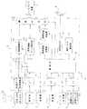
図1は本発明の一実施形態に係る車載用ナビゲーション装置の構成を概略的に示したものである。
【0020】
図示の車載用ナビゲーション装置30において、1はDVD−ROMドライブを示し、このDVD−ROMドライブ1によって駆動されるDVD−ROM1aには、縮尺レベル(1/12500、1/25000、1/50000等)に応じて適当な大きさの経度幅及び緯度幅に区切られた地図データが予め格納されている。この地図データは、経緯度で表現された点(ノード)の座標集合で表されており、また、道路は2以上のノードの連結からなり、2つのノードを連結した部分はリンクと呼ばれる。地図データは、道路リスト、ノードテーブル、交差点構成ノードリスト、交差点ネットリスト等からなるマップマッチング用及び経路探索用の道路レイヤ、地図画面上に道路、公園、河川、目印となる建物や施設等の各種物件を表示するための背景レイヤ、市町村名などの行政区画名、道路名、交差点名、建物の名前等の文字や地図記号等を表示するための文字・記号レイヤなどから構成されている。
【0021】
地図データを構成する各種レイヤのうち本発明に関連するのは道路レイヤであり、そのデータ構造について特に図示はしないが、道路リストは、道路毎に、道路の種別(道路クラス)、道路を構成するノードの数、道路を構成する各ノードのノードテーブル上での位置と、次のノードまでの幅員等のデータから構成されている。また、交差点構成ノードリストは、地図上の各交差点毎に、当該交差点に連結するリンク他端ノード(「交差点構成ノード」という。)のノードテーブル上での位置の集合からなっている。ノードテーブルは地図上の全ノードのリストであり、ノード毎に位置情報(経緯度で表現された点の座標データ)、当該ノードが交差点であるか否かを指示する交差点識別フラグ、交差点の場合には交差点構成ノードリスト上での当該ノードの位置を示すポインタ、交差点でない場合には道路リスト上で当該ノードが属する道路の位置を示すポインタ等によって構成されている。また、交差点ネットリストは、交差点を構成するノードを特定するID情報(当該交差点のシーケンシャル番号、当該交差点ノードが含まれる区分地図の番号等)、交差点構成ノード数、各隣接交差点のシーケンシャル番号、各隣接交差点までの距離と道路の属性(道路種別、幅員)等のデータからなっている。さらに、ノードテーブルにおいて交差点を指示するノードには、当該交差点に信号機が付属しているか否かを指示する信号機識別情報が付加されており、信号機が付属している場合には、赤信号時に右折禁止か否かを指示する赤信号時右折可否識別情報も付加されている。
【0022】
また、2は後述するナビゲーション装置本体10を操作するための操作部を示し、例えば、リモコン送信器の形態を有している。特に図示はしないが、かかるリモコン送信器には、ディスプレイ装置(後述)の画面上の各種メニュー、各種項目等を選択したり、選択したメニュー等を実行させるための各種操作ボタン、ジョイスティック等が適宜設けられている。また、3は各種のサービスセンタと通信するための車載電話機等の通信機、4は電波ビーコン又は光ビーコンから送られてくるVICS(道路交通情報通信システム)情報を受信するVICS受信機、5はGPS衛星から送られてくるGPS信号を受信するGPS受信機、6は自立航法センサを示す。この自立航法センサ6は、自車の進行方位を検出するためのジャイロ等の角度センサ6aと、一定の走行距離毎にパルスを発生する距離センサ6bとにより構成されており、自車の走行速度を検出し、またGPS受信機5と協働して自車の現在位置を検出するのに用いられる。
【0023】
また、7はLCD等のディスプレイ装置を示し、後述するナビゲーション装置本体10からの制御に基づいて、基本的にはナビゲーションに係る案内情報(自車の現在位置(車両位置マーク)及びその周囲の地図、出発地から目的地までの誘導経路、その他の案内情報等)を画面上でユーザ(特に運転者)に提供するものである。8はスピーカを示し、後述するナビゲーション装置本体10からの制御に基づいて、上記のナビゲーションに係る案内情報を音声によりユーザに提供するものである。
【0024】
また、ナビゲーション装置本体10において、11はDVD−ROMドライブ1を介してDVD−ROM1aから地図データを読み取るための地図データ読取制御部、12は地図データ読取制御部11により読み出された地図データを一時的に格納するバッファメモリ、13,14,15,16及び17はそれぞれ操作部2、通信機3、VICS受信機4、GPS受信機5及び自立航法センサ6に接続されるインタフェース(I/F)を示す。
【0025】
また、18はマイクロコンピュータ等により構成された制御部を示し、この制御部18は、ナビゲーション用のプログラム(経路探索の処理やそれに基づく経路案内に必要な表示出力制御等を行うためのプログラム)を内蔵しており、このプログラムに従い、GPS受信機5及び自立航法センサ6から出力される各信号に基づいて自車の現在位置を検出したり、自立航法センサ6から出力される信号に基づいて自車の走行速度(車速)を算出したり、地図データ読取制御部11を制御して、表示させたい地図のデータをDVD−ROMドライブ1を介してDVD−ROM1aからバッファメモリ12に読み出したり、バッファメモリ12に読み出した地図データを用いて設定された探索条件で出発地(自車の現在位置)から目的地までの誘導経路を探索するなど、ナビゲーションに係る種々の処理を実行する。さらに制御部18は、後述するように車載用ナビゲーション装置30が行う経路探索に係る通行コスト算出処理を制御する機能を有している。
【0026】
また、19はバッファメモリ12に読み出された地図データを用いて地図画像の描画処理を行う地図描画部、20は動作状況に応じて各種メニュー画面(操作画面)及び車両位置マーク、カーソル等の各種マークを生成する操作画面・マーク発生部、21は誘導経路に関するデータを格納しておくための誘導経路記憶部を示す。この誘導経路記憶部21には、制御部18によって探索された誘導経路の出発地から目的地までの道路を構成する全てのノード(経緯度で表現された点の座標)に関するデータを経路順に並べたノードデータ列(誘導経路データ)が格納される。また、22は誘導経路描画部を示し、誘導経路記憶部21から誘導経路データを読み出して、当該誘導経路を他の道路とは異なる表示態様(色を変える、線幅を太くするなど)で描画する機能を有している。
【0027】
また、23は画像合成部を示し、制御部18からの制御に基づいて、地図描画部19で描画された地図画像に、誘導経路描画部22で描画された誘導経路、操作画面・マーク発生部20で生成された操作画面及び各種マーク等を重ね合わせて、ディスプレイ装置7の画面上に表示させる機能を有している。24は音声出力部を示し、制御部18からの制御に基づいて音声信号(ナビゲーションに係る案内情報)をスピーカ8に出力する。
【0028】
また、25は制御部18に接続されたEEPROM等のメモリからなる通行コスト格納部を示す。この通行コスト格納部25には、DVD−ROM1aに格納されている地図データを構成する道路レイヤ(道路リスト、ノードテーブル、交差点構成ノードリスト、交差点ネットリスト等)のデータに対応させて、リンクコストと、当該リンクの他端ノード(交差点構成ノード)での交差点通過方向コスト(右左折等角度コスト)の各データが格納されている。
【0029】
リンクコストは、式(1)で定義したような道路クラスコストに相当し、道路種別に応じて走行速度の速い道路ほど小さくなるように定められた値(相対値)である。一方、交差点通過方向コスト(右左折等角度コスト)は、当該交差点での通過方向(右折角度、左折角度等)と、当該交差点に信号機が付属しているか否かを指示する信号機識別情報と、赤信号時に右折禁止か否かを指示する赤信号時右折可否識別情報とに応じてそれぞれ一定の規則に基づき定められた値(相対値)である。
【0030】
なお、本実施形態では、通行コスト格納用のメモリ(通行コスト格納部25)を地図データ格納用のDVD−ROM1aと別個に設けているが、DVD−ROM1aの記憶容量に十分な余裕がある場合には、通行コストの各データを地図データと共にDVD−ROM1aに格納するようにしてもよい。この場合、通行コストを格納するための専用のメモリ(通行コスト格納部25)を不要とすることができる。
【0031】
以上のように構成された車載用ナビゲーション装置30において、DVD−ROM1aは「第1の記憶手段」に、制御部18は「制御手段」に、通行コスト格納部25は「第2の記憶手段」にそれぞれ対応している。
【0032】
本実施形態に係る車載用ナビゲーション装置30では、その基本的な動作として、制御部18は、GPS受信機5で受信したGPS信号と自立航法センサ6から入力した信号とに基づいて自車の現在位置を検出する。そして、DVD−ROMドライブ1を介してDVD−ROM1aから自車周囲の地図データを読み出してバッファメモリ12に格納する。地図描画部19は、バッファメモリ12に読み出された地図データに基づいて地図画像を生成し、画像合成部23を介してディスプレイ装置7の画面上に自車周囲の地図画像を表示する。
【0033】
また、制御部18は、自車の移動に伴ってGPS受信機5及び自立航法センサ6から入力した各信号に基づいて自車の現在位置を検出し、その検出結果に応じて、ディスプレイ装置7の画面上に表示された地図画像に車両位置マークを重ね合わせて表示し、自車の移動に伴って車両位置マークを移動させたり、地図画像をスクロール表示する。
【0034】
さらに、ユーザが操作部2(リモコン送信器)を操作して目的地及びその他必要な情報(目的地に至る途中の経由地の情報等)を設定すると、制御部18は、GPS受信機5及び自立航法センサ6からの各信号に基づいて検出した自車の現在位置を出発地とし、後述するように、出発地から目的地まで通行コストが最も低い経路をDVD−ROM1aの地図データを用いて探索する。そして、探索により得られた経路を誘導経路(データ)として誘導経路記憶部21に格納し、誘導経路描画部22及び画像合成部23を介してディスプレイ装置7に対し、画面上の地図画像に誘導経路を重ね合わせて表示させる。このとき、誘導経路を、ユーザが識別し易いように他の道路とは異なる表示態様(例えば、線幅を太くしたり、目立つ色で表示したりするなど)で表示させる。このように制御部18は、自車の走行に伴って適宜案内情報を出力し、自車を目的地まで誘導経路に沿って走行するように案内する。これによって、ユーザは、ディスプレイ装置7の画面を通して目的地まで自車が案内されるべき誘導経路を把握することができる。
【0035】
以下、本実施形態に係る車載用ナビゲーション装置30が行う経路探索に係る通行コスト算出処理について、その処理フローの一例を示す図2及び図3を参照しながら説明する。
【0036】
先ず、初期状態において、自車の現在位置は交差点(ノード)上にあるものとする。この状態で、最初のステップS1では、制御部18において、ユーザが操作部2(リモコン送信器)を操作して目的地を設定したことをインタフェース13を介して検出する。説明の便宜上、この目的地についても交差点(ノード)上にあるものとする。
【0037】
次のステップS2では、制御部18が、操作部2を介して入力された目的地のデータと、GPS受信機5及び自立航法センサ6からの各信号に基づき検出した自車の現在位置を出発地として設定した出発地のデータとに基づき、地図データ読取制御部11を制御して、出発地から目的地までが入る範囲の地図データをDVD−ROMドライブ1を介してDVD−ROM1aからバッファメモリ12に読み出す。そして、この読み出した地図データに基づいて、以下に記述するように出発地から目的地までのトータルの通行コストが最小になるような経路(最適な誘導経路)を横型探索法などにより探索する。
【0038】
次のステップS3では、制御部18が、バッファメモリ12に読み出した地図データ(道路リスト、ノードテーブル、交差点構成ノードリスト、交差点ネットリスト等)と、通行コスト格納部25に格納されているリンクコストのデータとを参照して、1番目のリンク、すなわち自車の現在位置である交差点(ノード)をその一端ノードとして含むリンクについて、そのリンクコスト(LCi)を設定する。この設定されたリンクコスト(LCi)は、レジスタ等(図示せず)にいったん格納される。
【0039】
次のステップS4では、制御部18が、当該地図データ(道路リスト、ノードテーブル、交差点構成ノードリスト、交差点ネットリスト等)を参照して、当該リンク(この場合、1番目のリンク)の他端ノード(交差点)において右折方向を設定した(YES)か否(NO)かを判定する。そして、判定結果がYESの場合にはステップS5に進み、判定結果がNOの場合にはステップS10にジャンプする。
【0040】
次のステップS5では、制御部18が、当該地図データ(ノードテーブルにおける付加情報としての信号機識別情報)を参照して、当該交差点に信号機が付属している(YES)か否(NO)かを判定する。そして、判定結果がYESの場合にはステップS6に進み、判定結果がNOの場合にはステップS9にジャンプする。
【0041】
次のステップS6では、制御部18が、当該地図データ(道路リスト、ノードテーブル、交差点構成ノードリスト、交差点ネットリスト等)を参照して、当該信号機は、原則的に「赤信号時右折禁止」の州に属するもの(YES)か否(NO)かを判定する。そして、判定結果がYESの場合にはステップS7に進み、判定結果がNOの場合にはステップS9にジャンプする。
【0042】
なお、ここで言及している「原則的に」とは、前述したように同じ州の中でも地域によっては右折可能であったり、あるいは右折禁止となっている場合もあることから、その州全体として見た場合に概ね「赤信号時右折禁止」となっている状況をいう。
【0043】
次のステップS7では、制御部18が、当該地図データ(ノードテーブルにおける付加情報としての赤信号時右折可否識別情報)を参照して、当該識別情報が「赤信号時右折禁止」を指示している(YES)か否(NO)かを判定する。そして、判定結果がYESの場合にはステップS8に進み、判定結果がNOの場合にはステップS9に進む。
【0044】
ステップS8では(すなわち、当該交差点に信号機が有って、その信号機が原則的に「赤信号時右折禁止」の州に属するものであり、かつ、当該交差点に「赤信号時右折禁止」の情報が付加されている場合)、制御部18が、当該地図データ(道路リスト、ノードテーブル、交差点構成ノードリスト、交差点ネットリスト等)と、通行コスト格納部25に格納されている交差点通過方向コスト(右左折等角度コスト)のデータとを参照して、当該リンクの他端ノード(交差点)での特定の右折角度コスト(NCi)を設定する。この特定の右折角度コストは、後述する通常の右折角度コストよりも大きい値に設定されている。この設定された特定の右折角度コスト(NCi)は、上記設定されたリンクコスト(LCi)と共にレジスタ等(図示せず)にいったん格納される。この後、ステップS11に進む。
【0045】
一方、ステップS9では(すなわち、当該交差点に信号機が無い場合、又は、信号機が有ってもその信号機が原則的に「赤信号時右折禁止」の州に属していない場合、又は、原則的に「赤信号時右折禁止」の州に属してはいるが当該交差点に「赤信号時右折禁止」の情報が付加されていない場合)、ステップS8で行った処理と同様にして、制御部18が、当該地図データと、交差点通過方向コスト(右左折等角度コスト)のデータとを参照して、当該リンクの他端ノード(交差点)での通常の右折角度コスト(NCi)を設定する。同様に、この設定された通常の右折角度コスト(NCi)はレジスタ等(図示せず)にいったん格納される。この後、ステップS11に進む。
【0046】
他方、ステップS10では(すなわち、当該リンクの他端ノード(交差点)において右折方向以外の方向を設定した場合)、ステップS8で行った処理と同様にして、制御部18が、当該地図データと、交差点通過方向コスト(右左折等角度コスト)のデータとを参照して、当該リンクの他端ノード(交差点)でのその他の交差点通過方向(左折等)コスト(NCi)を設定する。同様に、この設定された交差点通過方向(左折等)コスト(NCi)はレジスタ等(図示せず)にいったん格納される。この後、ステップS11に進む。
【0047】
ステップS11では、制御部18が、前述した式(1)に従って、当該リンクについての通行コスト(PCi)を算出する。すなわち、ステップS3で設定したリンクコスト(LCi)に、ステップS8〜S10のいずれかで設定した交差点通過方向(右左折等角度)コスト(NCi)を加算して通行コスト(PCi)を算出する(PCi=LCi+NCi)。
【0048】
次のステップS12では、制御部18において、次のリンク(1番目のリンクの他端ノード(交差点)に接続された2番目のリンク)以降、目的地までの各リンクについて、それぞれステップS3〜S11で行った処理と同様の処理を繰り返す。
【0049】
次のステップS13では、制御部18が、ステップS3〜S12の処理によって算出した出発地から目的地までの各リンク毎の通行コスト(PCi)を加算して、トータルの通行コスト(ΣPCi)を算出する。
【0050】
これによって、出発地(自車の現在位置)から目的地までの1つの経路についてその通行コスト(ΣPCi)が算出されたことになる。しかし実際は、自車の現在位置である交差点(ノード)には複数の道路(リンク)が接続されているため、その接続数に応じた1番目のリンクが存在する。従って、目的地までのトータルの通行コスト(ΣPCi)の計算は、出発地のノードに接続されているリンクの数だけ行われる。これは、ステップS3〜S13で行った処理と同様の処理を繰り返すことにより実行される。
【0051】
最後のステップS14では、制御部18が、ステップS13で算出した目的地までの複数の探索経路についての各々のトータルの通行コスト(ΣPCi)のうち、ΣPCiが最小となる経路のデータを誘導経路記憶部21に格納する。そして、本処理フローは「終了」となる。
【0052】
なお、誘導経路記憶部21に格納された誘導経路(データ)は、上述したように制御部18からの制御に基づいて、自車の走行中、誘導経路描画部22及び画像合成部23を介してディスプレイ装置7の画面上に、ユーザが識別し易い目立った表示態様で地図画像に重ね合わされて表示される。
【0053】
以上説明したように、本実施形態に係る車載用ナビゲーション装置30によれば、各州や地域毎に交通規則が異なる場合において出発地から目的地までの経路探索を行うにあたり、図2及び図3の処理フローに示したように交差点通過方向コスト(右左折等角度コスト)を設定することで(ステップS8〜S10)、例えば、赤信号時右折禁止の州(地域)においては信号機の無い交差点で右折するような経路を探索することができ、また、赤信号時右折可能な州(地域)においては積極的に当該交差点を右折するような経路を探索することができる。
【0054】
つまり、各州や地域毎の交通規則の違い(赤信号時の右折可否など)を探索経路についての通行コストに反映させているので、各州や地域毎にユーザが希望する経路(最適な誘導経路)を常に提供することが可能となる。
【0055】
なお、上述した実施形態では、各州や地域毎の交通規則の違いを反映させた情報の一例として、赤信号時に右折禁止か否かを指示する赤信号時右折可否識別情報を利用した場合について説明したが、交通規則の違いを反映させた情報はこれに限定されないことはもちろんである。例えば、右折禁止の代わりに左折禁止に係る識別情報を利用することも可能である。
【0056】
【発明の効果】
以上説明したように本発明によれば、各州や地域毎に異なる交通規則の違いを探索経路についての通行コストに反映させることにより、ユーザにとって常に最適な誘導経路を提供することが可能となる。
【図面の簡単な説明】
【図1】本発明の一実施形態に係る車載用ナビゲーション装置の構成を概略的に示すブロック図である。
【図2】図1の車載用ナビゲーション装置が行う経路探索に係る通行コスト算出処理の一例を示すフロー図である。
【図3】図2の処理フローに続く処理を示すフロー図である。
【符号の説明】
1a…DVD−ROM(第1の記憶手段)、
2…操作部、
4…GPS受信機、
6…自立航法センサ、
7…ディスプレイ装置、
18…制御部(制御手段)、
19…地図描画部、
20…操作画面・マーク発生部、
22…誘導経路描画部、
23…画像合成部、
25…通行コスト格納部(第2の記憶手段)、
30…車載用ナビゲーション装置。[0001]
BACKGROUND OF THE INVENTION
The present invention relates to an in-vehicle navigation device, and in particular, when a route search to a destination is performed when a traffic rule is different for each state or region as in Europe and the United States, the difference in the traffic rule is determined as a traffic cost for the searched route. The present invention relates to an in-vehicle navigation device having a function to be reflected on the vehicle.
[0002]
[Prior art]
In a conventional typical vehicle-mounted navigation device, a CPU that controls all processing related to navigation, a storage device such as a CD-ROM or DVD-ROM that stores map data in advance, a display device, and the current position of the vehicle GPS (Global Positioning System) for detecting the vehicle, a gyro for detecting the traveling direction and traveling speed of the own vehicle, a vehicle speed sensor, etc., and map data including the current position of the own vehicle by the CPU From the storage device, and based on this map data, a map image around the vehicle position is drawn on the display screen, and a vehicle position mark indicating the current position of the vehicle is superimposed on the display screen and displayed. Scroll the map image as the car moves, or fix the map image to the screen and move the vehicle position mark It is possible to see at a glance where the car is currently driving.
[0003]
In-vehicle navigation devices are usually equipped with a function (route guidance function) that guides a user so that the user can easily travel on the road without making a mistake. According to this route guidance function, the CPU calculates the optimal route (typically the route with the lowest cost) from the starting point to the destination using the map data, such as a horizontal search method or Dijkstra method. To automatically search and store the searched route as a guide route so that it can be distinguished from other roads on the map image while driving (for example, changing the color or changing the line width) When the vehicle approaches the intersection where the course should be changed on the guidance route within a predetermined distance, an enlarged map of the intersection is displayed on the map image and an arrow indicating the intersection passing direction is displayed. By doing so, the user can grasp the guidance route to the destination.
[0004]
Here, the cost is a numerical value of the appropriate degree as a guide route, and the cost related to a node (a point expressed by longitude and latitude) and a link (a portion connecting two nodes, that is, a road) There are two types of costs related to (part). The cost of the link is a coefficient determined based on certain rules according to the road type (road class), the number of lanes, the road width, etc. indicating whether it is a general road or a highway based on the distance (road length) For example, a value (relative value) multiplied by (a coefficient with a predetermined weighting) or a predicted traveling time of the vehicle. On the other hand, the cost associated with a node is a coefficient (coefficient with a predetermined weight) determined based on certain rules depending on the passing direction at the intersection (right turn angle, left turn angle, etc.) and the presence or absence of traffic lights at the intersection. ) Multiplied by (relative value).
[0005]
Therefore, even if there are two routes having the same distance, the cost differs depending on whether the user uses a toll road, whether the travel distance is prioritized or the travel time is prioritized. Even if you pass through the same intersection, the cost varies depending on whether you turn right, turn left, or go straight, and even if you make a right turn (left turn) at the same intersection, depending on the angle of turn But the cost will be different.
[0006]
In a conventional in-vehicle navigation device, a route to a destination is calculated using a network in which an actual road that is running is abstracted into nodes and links. The “optimum route” to the destination is the sum of the link cost for each link from the departure point to the destination and the intersection direction cost (right and left turn equiangular cost) for each node. , The total link cost to the destination) is minimized.
[0007]
The traffic cost when passing through each link is calculated by the following equation (1), for example.
[0008]
[0009]
On the other hand, in a normal vehicle-mounted navigation device, a route search is performed in consideration of traffic rules such as right / left turn prohibition and one-way traffic. For this reason, the guidance route guided on the display screen is a route that complies with the traffic rules.
[0010]
As a technology related to the route search in consideration of such traffic rules, for example, in an emergency vehicle such as an ambulance, based on the driving state, in the case of emergency driving, a search condition that excludes traffic regulation conditions such as a right turn prohibition. There is one that performs a route search (see, for example, Patent Document 1). In addition, as a technique for providing a route with the lowest cost from the departure point to the destination, for example, parameters (distance, time, cost, etc.) when performing a route search based on a user's manual operation are changed. (For example, refer to Patent Document 2).
[0011]
[Patent Document 1]
JP 2000-298030 A
[Patent Document 2]
JP-A-5-126590
[0012]
[Problems to be solved by the invention]
As described above, the conventional in-vehicle navigation device basically guides a route that minimizes the total travel cost from the departure point to the destination as a guide route (recommended route), and this guide route is a traffic route. The route followed the rules.
[0013]
However, actual traffic rules vary from region to region. Especially in the United States, traffic rules may vary from state to state. For example, in California, only a right turn is possible when the light is red, but some states cannot turn right when the light is red. Also, within the same state, there are cases where it is possible to make a right turn or a right turn is prohibited (for example, the Manhattan area of New York).
[0014]
In conventional in-vehicle navigation devices, such differences in traffic rules between states and regions have not been reflected in the travel costs for the searched route. For this reason, a route different from the route desired by the user may be guided as a recommended route depending on the region. That is, there is a problem in that the route desired by the user cannot always be provided due to the difference in traffic rules in each state or region.
[0015]
The present invention was created in view of the problems in the prior art, and provides an in-vehicle navigation device that can always provide an optimum guidance route for a user even when the traffic rules differ for each state or region. With the goal.
[0016]
[Means for Solving the Problems]
In order to solve the above-described problems of the prior art, according to the present invention, when a route search to a destination is performed, a traffic cost to the destination is calculated using a network in which an actual road is abstracted into nodes and links. In the in-vehicle navigation device having a function to perform the first information, the first information that indicates whether or not a traffic light is attached to the intersection, and the second information that reflects the difference in traffic rules that differ in each state or region First storage means storing map data including the link cost determined based on a certain rule according to the road type, the number of lanes, the right and left turn equiangularity at the intersection of each node, the first information And second storage means for storing each data of intersection passing direction cost determined based on a certain rule according to the second information, and operably connected to the first and second storage means Control means The control means refers to the map data, the link cost, and the intersection direction cost when the destination is set, and links each link from the current position of the vehicle to the destination. An in-vehicle navigation device characterized in that a link cost and an intersection passing direction cost are set for each, and the set cost is added to perform a route search that minimizes the traffic cost to the destination. Provided.
[0017]
According to the in-vehicle navigation device according to the present invention, when the route search from the departure place to the destination is performed when the traffic rules are different for each state or region, the difference in the traffic rules (for example, the right turn prohibition at red light, Since a right turn at the time of a red light is reflected in the travel cost for the searched route, the route desired by the user can be provided for each state or region. That is, it is possible to always provide an optimum guide route for the user even when the traffic rules differ for each state or region.
[0018]
DETAILED DESCRIPTION OF THE INVENTION
Hereinafter, embodiments of the present invention will be described with reference to the accompanying drawings.
[0019]
FIG. 1 schematically shows the configuration of an in-vehicle navigation device according to an embodiment of the present invention.
[0020]
In the illustrated in-
[0021]
Of the various layers constituting the map data, the road layer is relevant to the present invention, and the data structure is not particularly shown, but the road list comprises the road type (road class) and road for each road. It is composed of data such as the number of nodes to be performed, the position of each node constituting the road on the node table, and the width to the next node. The intersection configuration node list includes a set of positions on the node table of link other end nodes (referred to as “intersection configuration nodes”) connected to the intersection for each intersection on the map. The node table is a list of all nodes on the map. For each node, position information (coordinate data of points expressed in longitude and latitude), intersection identification flag indicating whether the node is an intersection, and in the case of an intersection Is composed of a pointer indicating the position of the node on the intersection constituting node list, and a pointer indicating the position of the road to which the node belongs on the road list if the intersection is not an intersection. In addition, the intersection netlist includes ID information (sequential number of the intersection, the number of a division map including the intersection node, etc.), the number of nodes constituting the intersection, the sequential number of each adjacent intersection, It consists of data such as distance to adjacent intersections and road attributes (road type, width). Furthermore, a traffic signal identification information indicating whether or not a traffic signal is attached to the intersection is added to the node that indicates the intersection in the node table. Identification information for whether or not to turn right at the time of a red signal instructing whether or not to prohibit is also added.
[0022]
Reference numeral 2 denotes an operation unit for operating a
[0023]
Reference numeral 7 denotes a display device such as an LCD. Basically, guidance information related to navigation (current position of the vehicle (vehicle position mark) and a map around it based on control from the
[0024]
In the
[0025]
[0026]
[0027]
[0028]
[0029]
The link cost corresponds to a road class cost as defined by equation (1), and is a value (relative value) determined so as to decrease as the road travels faster according to the road type. On the other hand, the intersection passing direction cost (right-left turn equal angle cost) is the passing direction (right turn angle, left turn angle, etc.) at the intersection, and traffic signal identification information indicating whether a traffic light is attached to the intersection, These are values (relative values) determined based on certain rules according to the right turn right turn permission / inhibition identification information for instructing whether or not a right turn is prohibited at the time of a red light.
[0030]
In the present embodiment, the memory for storing the traffic cost (the traffic cost storage unit 25) is provided separately from the DVD-ROM 1a for storing the map data. However, the storage capacity of the DVD-ROM 1a has a sufficient margin. Alternatively, each data of the traffic cost may be stored in the DVD-ROM 1a together with the map data. In this case, a dedicated memory (the traffic cost storage unit 25) for storing the traffic cost can be eliminated.
[0031]
In the in-
[0032]
In the in-
[0033]
Further, the
[0034]
Further, when the user operates the operation unit 2 (remote control transmitter) to set the destination and other necessary information (such as information about the waypoint on the way to the destination), the
[0035]
Hereinafter, the traffic cost calculation processing related to the route search performed by the vehicle-mounted
[0036]
First, in the initial state, it is assumed that the current position of the vehicle is on an intersection (node). In this state, in the first step S1, the
[0037]
In the next step S2, the
[0038]
In the next step S3, the map data (road list, node table, intersection configuration node list, intersection net list, etc.) read out by the
[0039]
In the next step S4, the
[0040]
In the next step S5, the
[0041]
In the next step S6, the
[0042]
Note that “in principle” as referred to here means that in the same state as mentioned above, depending on the region, it is possible to make a right turn or a right turn is prohibited. When viewed, it is a situation that is generally "no right turn at red light".
[0043]
In the next step S7, the
[0044]
In step S8 (that is, there is a traffic light at the intersection, the traffic light belongs to the state of “no right turn at red light” in principle), and information on “no right turn at red light” is present at the intersection. ) Is added to the map data (road list, node table, intersection configuration node list, intersection net list, etc.) and the intersection passing direction cost stored in the traffic cost storage unit 25 ( A specific right turn angle cost (NCi) at the other end node (intersection) of the link is set with reference to the data of right and left turn equal angle cost). This specific right turn angle cost is set to a value larger than a normal right turn angle cost described later. The set right turn angle cost (NCi) is temporarily stored in a register or the like (not shown) together with the set link cost (LCi). Thereafter, the process proceeds to step S11.
[0045]
On the other hand, in step S9 (that is, when there is no traffic light at the intersection, or when there is a traffic light, the traffic light is not in the state of “no right turn at red light” in principle, or in principle. If the information belongs to the state of “no right turn at red light” but the information of “no right turn at red light” is added to the intersection), the
[0046]
On the other hand, in step S10 (that is, when a direction other than the right turn direction is set at the other end node (intersection) of the link), the
[0047]
In step S11, the
[0048]
In the next step S12, the
[0049]
In the next step S13, the
[0050]
As a result, the traffic cost (ΣPCi) is calculated for one route from the departure point (the current position of the vehicle) to the destination. However, actually, since a plurality of roads (links) are connected to the intersection (node) which is the current position of the own vehicle, a first link corresponding to the number of connections exists. Accordingly, the total traffic cost (ΣPCi) to the destination is calculated by the number of links connected to the departure node. This is executed by repeating the same process as the process performed in steps S3 to S13.
[0051]
In the last step S14, the
[0052]
The guidance route (data) stored in the guidance
[0053]
As described above, according to the vehicle-mounted
[0054]
In other words, differences in traffic rules between states and regions (such as whether to turn right at red light) are reflected in the travel costs for the searched route, so the route desired by the user for each state or region (optimum guidance route) Can always be provided.
[0055]
In the above-described embodiment, as an example of information reflecting the difference in traffic rules for each state or region, a case where the right turn right / no-turn identification information indicating whether or not to turn right at the time of red light is used will be described. However, the information reflecting the difference in traffic rules is not limited to this. For example, it is also possible to use identification information relating to a left turn prohibition instead of a right turn prohibition.
[0056]
【The invention's effect】
As described above, according to the present invention, it is possible to always provide an optimum guide route for the user by reflecting the difference in traffic rules in each state or region in the travel cost of the searched route.
[Brief description of the drawings]
FIG. 1 is a block diagram schematically showing the configuration of an in-vehicle navigation device according to an embodiment of the present invention.
FIG. 2 is a flowchart showing an example of a traffic cost calculation process related to a route search performed by the in-vehicle navigation device of FIG.
FIG. 3 is a flowchart showing processing subsequent to the processing flow of FIG. 2;
[Explanation of symbols]
1a ... DVD-ROM (first storage means),
2 ... operation part,
4 ... GPS receiver,
6 ... Self-contained navigation sensor,
7 ... display device,
18 ... control part (control means),
19 ... Map drawing part,
20 ... operation screen / mark generator,
22 ... guide route drawing unit,
23. Image composition unit,
25: Traffic cost storage unit (second storage means),
30: In-vehicle navigation device.
Claims (7)
Translated fromJapanese交差点に信号機が付属しているか否かを指示する第1の情報と、各州や地域毎に異なる交通規則の違いを反映させた第2の情報とを含む地図データを格納した第1の記憶手段と、
道路種別や車線数等に応じて一定の規則に基づき定められたリンクコストと、各ノードの交差点での右左折等角度、前記第1の情報及び前記第2の情報に応じて一定の規則に基づき定められた交差点通過方向コストの各データを格納した第2の記憶手段と、
前記第1及び第2の記憶手段に動作可能に接続された制御手段とを備え、
該制御手段は、目的地の設定が行われたときに前記地図データと前記リンクコスト及び交差点通過方向コストの各データを参照して、自車の現在位置から目的地までの各リンク毎にそれぞれリンクコストと交差点通過方向コストを設定し、該設定した各コストを加算して前記目的地までの通行コストが最小になるような経路探索を行うことを特徴とする車載用ナビゲーション装置。In the in-vehicle navigation device with the function of calculating the travel cost to the destination using a network that abstracts the actual road into nodes and links when searching for the route to the destination,
First storage means for storing map data including first information indicating whether or not a traffic light is attached to an intersection and second information reflecting a difference in traffic rules different in each state or region When,
The link cost determined based on a certain rule according to the road type, the number of lanes, etc., the right and left turn equal angle at the intersection of each node, the first information and the second information Second storage means for storing each data of the intersection passing direction cost determined on the basis of;
Control means operably connected to the first and second storage means,
The control means refers to the map data, the link cost, and the intersection direction cost when the destination is set, and for each link from the current position of the vehicle to the destination. A vehicle-mounted navigation device characterized by setting a link cost and an intersection passing direction cost, and adding the set costs to perform a route search that minimizes the traffic cost to the destination.
Priority Applications (1)
| Application Number | Priority Date | Filing Date | Title |
|---|---|---|---|
| JP2002301304AJP4024638B2 (en) | 2002-10-16 | 2002-10-16 | Car navigation system |
Applications Claiming Priority (1)
| Application Number | Priority Date | Filing Date | Title |
|---|---|---|---|
| JP2002301304AJP4024638B2 (en) | 2002-10-16 | 2002-10-16 | Car navigation system |
Publications (2)
| Publication Number | Publication Date |
|---|---|
| JP2004138421A JP2004138421A (en) | 2004-05-13 |
| JP4024638B2true JP4024638B2 (en) | 2007-12-19 |
Family
ID=32449680
Family Applications (1)
| Application Number | Title | Priority Date | Filing Date |
|---|---|---|---|
| JP2002301304AExpired - Fee RelatedJP4024638B2 (en) | 2002-10-16 | 2002-10-16 | Car navigation system |
Country Status (1)
| Country | Link |
|---|---|
| JP (1) | JP4024638B2 (en) |
Families Citing this family (6)
| Publication number | Priority date | Publication date | Assignee | Title |
|---|---|---|---|---|
| WO2007043437A1 (en)* | 2005-10-14 | 2007-04-19 | Pioneer Corporation | Route guidance device, route guidance method, route guidance program, and computer-readable recording medium |
| WO2007043436A1 (en)* | 2005-10-14 | 2007-04-19 | Pioneer Corporation | Route guidance device, route guidance method, route guidance program, and computer-readable recording medium |
| JP4989981B2 (en)* | 2007-01-16 | 2012-08-01 | クラリオン株式会社 | Navigation device |
| JP5595293B2 (en)* | 2011-01-21 | 2014-09-24 | アルパイン株式会社 | Navigation device and cost calculation method in landabout |
| KR101501526B1 (en)* | 2013-07-24 | 2015-03-12 | 재단법인대구경북과학기술원 | Apparatus and method for route guidance using directional turning movement of vehicle |
| US9163950B2 (en) | 2014-01-24 | 2015-10-20 | Maan ALDUAIJI | Vehicle navigation device, a method for navigating and a non-transitory computer readable medium |
- 2002
- 2002-10-16JPJP2002301304Apatent/JP4024638B2/ennot_activeExpired - Fee Related
Also Published As
| Publication number | Publication date |
|---|---|
| JP2004138421A (en) | 2004-05-13 |
Similar Documents
| Publication | Publication Date | Title |
|---|---|---|
| US6732049B2 (en) | Vehicle navigation system and method | |
| US8670922B2 (en) | Guiding route generation device and guiding route generation method | |
| JP3443975B2 (en) | Guidance device | |
| JP2003214879A (en) | Navigation system | |
| JP2003121186A (en) | Guide route searching method for navigator | |
| JP2009150821A (en) | Onboard navigation device | |
| JP2006200978A (en) | Guide route generation device and guide route generation method | |
| JP2002090167A (en) | Route guiding method for on-vehicle navigation device | |
| JP4461041B2 (en) | Guide route generation device, vehicle navigation system, and guide route generation method | |
| JP3941605B2 (en) | Car navigation system | |
| JP2009270886A (en) | On-vehicle navigation device | |
| JP4024638B2 (en) | Car navigation system | |
| JP2002071369A (en) | On-vehicle navigation device | |
| JP2008045933A (en) | Road map display apparatus for vehicle | |
| JP3961378B2 (en) | Car navigation system | |
| JP2012149957A (en) | On-vehicle map display device | |
| JP2005003419A (en) | Vehicle-mounted navigation apparatus | |
| JP2001116574A (en) | Navigation device | |
| JP2005077187A (en) | In-vehicle navigation device and route guiding method | |
| JP2005017037A (en) | Navigation system | |
| JP3737875B2 (en) | Navigation device | |
| JP2003042787A (en) | Navigation system and navigation program | |
| JP4969392B2 (en) | Navigation device | |
| JP4731263B2 (en) | Navigation device and map display method | |
| JP2006162398A (en) | Navigation device and navigation method |
Legal Events
| Date | Code | Title | Description |
|---|---|---|---|
| A621 | Written request for application examination | Free format text:JAPANESE INTERMEDIATE CODE: A621 Effective date:20050930 | |
| A977 | Report on retrieval | Free format text:JAPANESE INTERMEDIATE CODE: A971007 Effective date:20070828 | |
| TRDD | Decision of grant or rejection written | ||
| A01 | Written decision to grant a patent or to grant a registration (utility model) | Free format text:JAPANESE INTERMEDIATE CODE: A01 Effective date:20071002 | |
| A61 | First payment of annual fees (during grant procedure) | Free format text:JAPANESE INTERMEDIATE CODE: A61 Effective date:20071003 | |
| R150 | Certificate of patent or registration of utility model | Ref document number:4024638 Country of ref document:JP Free format text:JAPANESE INTERMEDIATE CODE: R150 Free format text:JAPANESE INTERMEDIATE CODE: R150 | |
| FPAY | Renewal fee payment (event date is renewal date of database) | Free format text:PAYMENT UNTIL: 20101012 Year of fee payment:3 | |
| FPAY | Renewal fee payment (event date is renewal date of database) | Free format text:PAYMENT UNTIL: 20101012 Year of fee payment:3 | |
| FPAY | Renewal fee payment (event date is renewal date of database) | Free format text:PAYMENT UNTIL: 20111012 Year of fee payment:4 | |
| FPAY | Renewal fee payment (event date is renewal date of database) | Free format text:PAYMENT UNTIL: 20111012 Year of fee payment:4 | |
| FPAY | Renewal fee payment (event date is renewal date of database) | Free format text:PAYMENT UNTIL: 20121012 Year of fee payment:5 | |
| FPAY | Renewal fee payment (event date is renewal date of database) | Free format text:PAYMENT UNTIL: 20121012 Year of fee payment:5 | |
| FPAY | Renewal fee payment (event date is renewal date of database) | Free format text:PAYMENT UNTIL: 20131012 Year of fee payment:6 | |
| LAPS | Cancellation because of no payment of annual fees |