JP4024585B2 - Image forming apparatus network system, image forming apparatus, control method, and control program - Google Patents
Image forming apparatus network system, image forming apparatus, control method, and control programDownload PDFInfo
- Publication number
- JP4024585B2 JP4024585B2JP2002123147AJP2002123147AJP4024585B2JP 4024585 B2JP4024585 B2JP 4024585B2JP 2002123147 AJP2002123147 AJP 2002123147AJP 2002123147 AJP2002123147 AJP 2002123147AJP 4024585 B2JP4024585 B2JP 4024585B2
- Authority
- JP
- Japan
- Prior art keywords
- image forming
- forming apparatus
- color
- printing
- toner
- Prior art date
- Legal status (The legal status is an assumption and is not a legal conclusion. Google has not performed a legal analysis and makes no representation as to the accuracy of the status listed.)
- Expired - Fee Related
Links
Images


Landscapes
- Facsimiles In General (AREA)
- Control Or Security For Electrophotography (AREA)
- Color Electrophotography (AREA)
Description
Translated fromJapanese【0001】
【発明の属する技術分野】
本発明は、画像形成装置ネットワークシステム、画像形成装置、制御方法及び制御プログラムに関し、特に2色以上の作像機構を有する2台以上の画像形成装置(デジタル複写機)間で画像データを転送し合う画像形成装置ネットワークシステム、画像形成装置、制御方法及び制御プログラムに関する。
【0002】
【従来の技術】
画像形成装置を2台以上接続したネットワークシステムは、従来より存在した。そのようなシステムとしては、例えば、特開2001−100956号公報に記載された画像形成装置連結システムが知られていた。このシステムは、各画像形成装置の記憶装置の使用状態を検知して、ジョブに使用する記憶装置を適宜割り付けることにより、記憶装置の使用効率の向上を図っている。
【0003】
【発明が解決しようとする課題】
しかし、このようなシステムにおいても、画像形成装置がカラー機の場合、連結された画像形成装置間における機内情報(特にトナー情報)の検知の問題が残っていた。すなわち、カラー機においては、ある特定のトナーがない場合、印刷可能な印刷色が変わることが知られている。連結された画像形成装置間においても、各モードや連結を設定する画像形成装置(以下親機という)と連結される側の画像形成装置(以下子機という)のトナー残量状態によって印刷可能な印刷色が異なってくる。よって、トナー残量状態によっては、印刷後の色の均一性が保てないことがある。例えば、印刷中にニアエンドになった場合、トナーエンドにより装置が停止するまでは印刷が続けられるので、最初と最後では印刷物の色が異なってしまうことがある。特に、業者による大量コピーの場合にはこのような事態が起こり易いし、現にそのような事態になれば、顧客または業者が余計な手間や費用を負担することになりかねない。
【0004】
そこで、本発明は、連結された各画像形成装置のトナー残量状態に応じて、印刷色の決定や印刷動作の割り当てを適宜行えるようにすることにより、ユーザの作業効率を向上させることができ、かつ、印刷された画像の均一性を保証(以下、画像の保証という)できる画像形成装置ネットワークシステム、画像形成装置、制御方法及び制御プログラムを提供することを目的とする。
【0005】
【課題を解決するための手段】
かかる目的を達成するために、本発明は以下の特徴を有することとする。
【0006】
本発明にかかる画像形成装置ネットワークシステムは、
複数の画像形成装置を連結した画像形成装置ネットワークシステムであって、
各画像形成装置における各色のトナー残量状態を、連結された他の前記画像形成装置に通知する通知手段と、
前記通知手段により通知された各画像形成装置の各色のトナー残量状態に応じて、連結複写を行う画像形成装置において印刷可能な印刷色内で印刷色を指定し、該指定した印刷色で連結複写を行う連結動作手段と、
前記連結動作手段により連結複写中となった画像形成装置において、前記指定した印刷色での印刷に必要なトナーがトナーエンドになった場合に、前記印刷色での印刷を中止する中止手段と、を有することを特徴とする。
【0007】
また、本発明にかかる画像形成装置ネットワークシステムは、
前記中止手段により前記印刷色での印刷を中止した場合に、残印刷内容を他の前記画像形成装置に割り当てる割当手段を有することを特徴とする。
【0008】
また、本発明にかかる画像形成装置は、
複数の画像形成装置を連結した画像形成装置ネットワークシステムを構成するマスタ側の画像形成装置であって、
各画像形成装置における各色のトナー残量状態を取得し、該取得した各画像形成装置の各色のトナー残量状態に応じて、連結複写を行う画像形成装置において印刷可能な印刷色内で印刷色を指定し、該指定した印刷色で連結複写を行う連結動作手段と、
前記連結動作手段により連結複写中となった前記マスタ側の画像形成装置において、前記指定した印刷色での印刷に必要なトナーがトナーエンドになった場合に、前記印刷色での印刷を中止する中止手段と、を有することを特徴とする。
【0009】
また、本発明にかかる画像形成装置は、
前記中止手段により前記印刷色での印刷を中止した場合に、残印刷内容を他の前記画像形成装置に割り当てる割当手段を有することを特徴とする。
【0010】
また、本発明にかかる画像形成装置は、
前記連結動作手段により連結複写中となった前記スレーブ側の画像形成装置において、前記指定した印刷色での印刷に必要なトナーがトナーエンドになり、前記印刷色での印刷を前記スレーブ側の画像形成装置において中止し、中止状態と残印刷内容とを前記スレーブ側の画像形成装置から受付けた場合に、前記残印刷内容を他の前記画像形成装置に割り当てる割当手段を有することを特徴とする。
【0011】
また、本発明にかかる画像形成装置は、
複数の画像形成装置を連結した画像形成装置ネットワークシステムを構成するスレーブ側の画像形成装置であって、
前記スレーブ側の画像形成装置における各色のトナー残量状態を、連結された他の画像形成装置に通知する通知手段と、
マスタ側の画像形成装置から前記各色のトナー残量状態に応じて指定された印刷色で連結複写を行う連結動作手段と、
前記連結動作手段により連結複写中となった前記スレーブ側の画像形成装置において、前記指定された印刷色での印刷に必要なトナーがトナーエンドになった場合に、前記印刷色での印刷を中止する中止手段と、を有することを特徴とする。
【0012】
また、本発明にかかる画像形成装置は、
前記中止手段により前記印刷色での印刷を中止した場合に、中止状態と残印刷内容とをマスタ側の画像形成装置に通知する通知手段を有することを特徴とする。
【0013】
また、本発明にかかる制御方法は、
複数の画像形成装置を連結した画像形成装置ネットワークシステムを構成するマスタ側の画像形成装置で行う制御方法であって、
各画像形成装置における各色のトナー残量状態を取得し、該取得した各画像形成装置の各色のトナー残量状態に応じて、連結複写を行う画像形成装置において印刷可能な印刷色内で印刷色を指定し、該指定した印刷色で連結複写を行う連結動作工程と、
前記連結動作工程により連結複写中となった前記マスタ側の画像形成装置において、前記指定した印刷色での印刷に必要なトナーがトナーエンドになった場合に、前記印刷色での印刷を中止する中止工程と、を前記マスタ側の画像形成装置が行うことを特徴とする。
また、本発明にかかる制御方法は、
複数の画像形成装置を連結した画像形成装置ネットワークシステムを構成するスレーブ側の画像形成装置で行う制御方法であって、
前記スレーブ側の画像形成装置における各色のトナー残量状態を、連結された他の画像形成装置に通知する通知工程と、
マスタ側の画像形成装置から前記各色のトナー残量状態に応じて指定された印刷色で連結複写を行う連結動作工程と、
前記連結動作工程により連結複写中となった前記スレーブ側の画像形成装置において、前記指定された印刷色での印刷に必要なトナーがトナーエンドになった場合に、前記印刷色での印刷を中止する中止工程と、を、前記スレーブ側の画像形成装置が行うことを特徴とする。
【0014】
また、本発明にかかる制御プログラムは、
複数の画像形成装置を連結した画像形成装置ネットワークシステムを構成するマスタ側の画像形成装置に実行させる制御プログラムであって、
各画像形成装置における各色のトナー残量状態を取得し、該取得した各画像形成装置の各色のトナー残量状態に応じて、連結複写を行う画像形成装置において印刷可能な印刷色内で印刷色を指定し、該指定した印刷色で連結複写を行う連結動作処理と、
前記連結動作処理により連結複写中となった前記マスタ側の画像形成装置において、前記指定した印刷色での印刷に必要なトナーがトナーエンドになった場合に、前記印刷色での印刷を中止する中止処理と、を前記マスタ側の画像形成装置に実行させることを特徴とする。
また、本発明にかかる制御プログラムは、
複数の画像形成装置を連結した画像形成装置ネットワークシステムを構成するスレーブ側の画像形成装置に実行させる制御プログラムであって、
前記スレーブ側の画像形成装置における各色のトナー残量状態を、連結された他の画像形成装置に通知する通知処理と、
マスタ側の画像形成装置から前記各色のトナー残量状態に応じて指定された印刷色で連結複写を行う連結動作処理と、
前記連結動作処理により連結複写中となった前記スレーブ側の画像形成装置において、前記指定された印刷色での印刷に必要なトナーがトナーエンドになった場合に、前記印刷色での印刷を中止する中止処理と、を、前記スレーブ側の画像形成装置に実行させることを特徴とする。
【0015】
【発明の実施の形態】
添付図面を参照して、本発明による画像形成装置及び画像形成装置ネットワークシステムの実施の形態を以下詳細に説明する。
【0016】
まず、図1〜図6を用いて、本発明による画像形成装置及び画像形成装置ネットワークシステムの一実施形態における画像形成装置について説明する。
【0017】
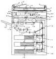
図1には、本発明による画像形成装置及び画像形成装置ネットワークシステムの一実施形態における画像形成装置(複写機)全体の概略図が示されている。
【0018】
自動原稿送り装置(以後ADFという)1にある、原稿台2に原稿の画像面を上にして置かれた原稿束は、手前側上面にある図2に示す操作部30上のスタートキー(プリントキー)34が押下されると、一番下の原稿から給送ローラ3と給送ベルトとによってコンタクトガラス6上の所定の位置に給送される。なお、ADF1は、一枚の原稿を給送完了に毎に原稿枚数をカウントアップするカウント機能を有している。
【0019】
コンタクトガラス6上に給送された原稿の画像データは、読み取りユニット50によって読み取られ、その後、読み取りが終了した原稿は、給送ベルト4及び排送ローラ5によって排出される。
【0020】
さらに、原稿セット検知7にて原稿台2に次の原稿が有ることが検知された場合、その原稿も前原稿と同様にコンタクトガラス6上に給送される。なお、給送ローラ3と、給送ベルト4と、排送ローラ5とは、図4に示す搬送モータ26によって駆動される。
【0021】
第1トレイ8と、第2トレイ9と、第3トレイ10とに積載された転写紙は、各々第1給紙装置11と、第2給紙装置12と、第3給紙装置13とによって給紙され、縦搬送ユニット14によって感光体15に当接する位置まで搬送される。
【0022】
読み取りユニット50にて読み込まれた画像データが、書き込みユニット57からのレーザーによって感光体15に書き込まれ、現像ユニット27を通過することによって、トナー像が形成される。そして、転写紙は、感光体15の回転と等速で搬送ベルト16によって搬送されながら、感光体15上のトナー像を転写される。その後、定着ユニット17にて画像を定着させ、排紙ユニット18によって排紙トレイ19に排出される。
【0023】
転写紙の両面に画像を作像する場合は、各給紙トレイ8〜10から給紙され作像された転写紙を排紙トレイ19側に導かないで、両面入紙搬送路113に搬送し、反転ユニット112でスイッチバック反転させ、両面搬送ユニット111に送る。両面搬送ユニット111に送られた用紙は、再度縦搬送ユニット14に送られて裏面に画像を印刷された後に排紙される。
【0024】
また、転写紙を反転して排出する場合は、上記のように反転ユニット112でスイッチバック反転した用紙を両面搬送ユニット111に送らずに反転排紙搬送路114に送り出して排紙する。
【0025】
感光体15と、搬送ベルト16と、定着ユニット17と、排紙ユニット18と、現像ユニット27とは、図4に示すメインモータ25によって駆動される。また、各給紙装置11〜13は、メインモータ25の駆動が各々図4の給紙クラッチ22〜24によって伝達されて駆動される。縦搬送ユニット14は、メインモータ25の駆動が同じく図4の中間クラッチ21によって伝達されて駆動される。
【0026】
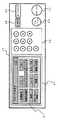
図2には、本発明による画像形成装置及び画像形成装置ネットワークシステムの一実施形態における画像形成装置(複写機)の操作部30が示されている。
【0027】
操作部30には、液晶タッチパネル31と、テンキー32と、クリア/ストップキー33と、プリントキー(スタートキー)34と、モードクリアキー35とがあり、液晶タッチパネル31には、機能キー37と、部数や画像形成装置の状態等を示すメッセージなどとが表示される。もっとも、ここで示したキーの名称、配置、表示されるメッセージの内容などは、一例にすぎず、この図に限定されるものではない。
【0028】
図3には、本発明による画像形成装置及び画像形成装置ネットワークシステムの一実施形態における画像形成装置(複写機)の操作部30内にある液晶タッチパネル31の表示例が示されている。
【0029】
オペレータが液晶タッチパネル31に表示されたキーにタッチすることで、選択された機能を示すキーが黒く反転する。また、機能の詳細を指定しなければならない場合(例えば変倍であれは変倍値等)は、キーにタッチすることで、詳細機能の設定画面が表示される。このように、液晶タッチパネル31は、ドット表示器を使用しているため、その時の最適な表示をグラフィカルに行うことが可能である。なお、操作部ないしタッチパネルは外付けも可能である。
【0030】
図3では、接続された画像形成装置と情報の送受信を行うか否かを設定するための表示部の一例が示されている。この場合、例えば、「連結」キーをタッチすることにより、接続されている複数の画像形成装置を用いた連結動作の設定が選択される。そして、自機が連結動作のマスター機として、後述のように、接続された自機以外の画像形成装置(スレーブ機)に対して動作の要求を行う。
【0031】
図4には、本発明による画像形成装置及び画像形成装置ネットワークシステムの一実施形態における画像形成装置のメインコントローラを中心にした制御装置の構成が示されている。メインコントローラ20には、操作部30と、画像処理ユニット(IPU)49と、原稿自動送り装置(ADF)1等の分散制御装置と、連結I/F48とが接続されている。
【0032】
メインコントローラ20は、画像形成装置全体を制御する。操作部30は、オペレータ(ユーザ)に対する表示およびオペレータ(ユーザ)からの機能設定入力制御を行う。画像処理ユニット(IPU)49は、スキャナの制御と、原稿画像を画像メモリに書き込む制御と、画像メモリからの作像を行う制御等とを行う。原稿自動送り装置(ADF)1については前述したとおりである。
【0033】
また、連結I/F48は、複数の画像形成装置に接続して各装置の構成、機能情報、および動作制御に関する情報の送受信を行う。メインコントローラ20は、連結I/F48を介して接続された画像形成装置の情報を獲得し、動作を設定することにより連結動作の制御を行う、もしくは接続された他の画像形成装置からの要求を獲得し自機の動作の制御を行う。また、各分散制御装置とメインコントローラ20は必要に応じて機械の状態、動作司令のやりとりを行っている。なお、前述したように、メインコントローラ20には紙搬送等に必要なメインモータ25や各種クラッチ21〜24も接続されている。
【0034】
以上説明した図を用いて、以下、本発明による画像形成装置及び画像形成装置ネットワークシステムの一実施形態における画像形成装置の原稿読み取りから、画像の書き込みまでの動作を説明する。
【0035】
読み取りユニット50は、原稿を載置するコンタクトガラス6と光学走査系で構成されており、光学走査系は、露光ランプ51と、第1ミラー52と、レンズ53と、CCDイメージセンサ54等とで構成されている。
【0036】
露光ランプ51及び第1ミラー52は、図示しない第1キャリッジ上に固定され、第2ミラー55及び第3ミラー56は図示しない第1キャリッジ上に固定されている。原稿像を読み取るときには、光路長が変わらないように、第1キャリッジと第2キャリッジとが2対1の相対速度で機械的に操作される。この光学走査系は、図示しないスキャナ駆動モータにて駆動される。
原稿画像は、CCDイメージセンサ54によって読み取られ、電気信号に変換されて処理される。
【0037】
書き込みユニット57は、レーザ出力ユニット58と、結像レンズ59と、ミラー60とで構成され、レーザ出力ユニット58の内部には、レーザ光源であるレーザダイオード及びモータによって高速で定速回転する多角形ミラー(ポリゴンミラー)が備わっている。
【0038】
書き込みユニット57から出力されるレーザ光が、画像作像系の感光体15に照射される。図示しないが感光体15の一端近傍のレーザビームを照射される位置に、主走査同期信号を発生するビームセンサが配置されている。
【0039】
図5には、本発明による画像形成装置ネットワークシステムの一実施形態における画像処理ユニット(IPU)49の内部構成のブロック図が示されている。
【0040】
図1の露光ランプ51から照射された光の反射を、CCDイメージセンサ54にて光電変換し、A/Dコンバータ61にてデジタル信号に変換する。デジタル信号に変換された画像信号は、シェーディング補正62がなされた後、画像処理部63にてMTF補正と、γ補正等とがなされる。変倍部72を経由した画像信号は変倍率に合せて拡大縮小され、セレクタ64に流れる。セレクタ64では、画像信号の送り先を、書き込みγ補正ユニット71にするか画像メモリコントローラ65にするかの切り替えが行われる。書き込みγ補正ユニット71を経由した画像信号は作像条件に合わせて書き込みγが補正され、書き込みユニット57に送られる。なお、画像メモリコントローラ65とセレクタ64の間は、双方向に画像信号を入出力可能な構成となっている。
【0041】
また、画像処理ユニット(IPU)49は、画像メモリコントローラ65等への設定や、図1の読み取り部50と書き込み部57の制御を行うCPU68と、そのプログラムやデータを格納するROM69と、RAM70とを備えている。さらにCPU68は、画像メモリコントローラ65を介して、画像メモリ66のデータの書き込み、読み出しが行える。
【0042】
連結I/F48は、画像情報の送受信のため、画像メモリコントローラ65のデータバスに接続され、データの入出力が可能な構成になっている。画像形成装置間のデータ転送速度に応じて、画像情報は画像メモリ66を介して転送される。すなわち、画像出力時にはメモリコントローラ65から画像メモリ66に画像データを格納した後、画像形成装置間のデータ転送速度に応じて順次画像メモリ66からデータを読み出して、連結I/F48によりデータを転送する。画像入力時には転送されてくる画像データを連結I/F48より画像メモリ66に格納した後、画像メモリ66からメモリコントローラ65を介して装置内部で画像データの処理を行う。
上述の構成により、画像形成装置の機能の制約を受けることなく連結動作の実現が可能となる。
【0043】
原稿画像で画像メモリコントローラ65へ送られた画像は、画像メモリコントローラ65内にある画像圧縮装置によって画像データを圧縮した後、画像メモリ66に送られる。ここで画像圧縮する理由は次のとおりである。
最大画像サイズ分の256階調のデータをそのまま画像メモリ66に書き込むことも可能であるが、1枚の原稿画像で画像メモリを大変多く使用する。画像圧縮を行うことで、限られた画像メモリを有効に利用できる。また、一度に多くの原稿画像データを記憶することができるため、ソート機能として、貯えられた原稿画像イメージデータをページ順に出力することができる。この場合画像を出力する際に画像メモリ66のデータを画像メモリコントローラ65内の伸長装置で順次伸長しながら出力を行う。このような機能は一般に「電子ソート」と呼ばれている。
また、画像メモリの機能を利用して、複数枚の原稿画像を、画像メモリの転写紙一枚分のエリアを分割したエリアに順次読み込むことも可能となる。例えば、4枚の原稿画像を、画像メモリの転写紙一枚分の4等分されたエリアに順次書き込むことで、4枚の原稿が一枚の転写紙イメージに合成され集約されたコピー出力を得ることが可能となる。このような機能は一般に「集約コピー」と呼ばれている。
【0044】
画像メモリ66の画像は、CPU68からアクセス可能な構成となっている。このため画像メモリの内容を加工することが可能であり、例えば、画像の間引き処理、画像の切り出し処理等が行える。加工には、画像メモリコントローラー65のレジスタにデータを書き込むことで画像メモリの処理を行うことができる。加工された画像は再度画像メモリ66に保持される。また、画像メモリ66の内容をCPU68が読みだし、I/Oポート67を経て、画像データ73として操作部30に転送することが可能な構成となっている。一般に、操作部30の画面表示解像度は低いため、画像メモリ66の原画像は画像間引きが行われ操作部30に送られる。
【0045】
なお、画像メモリ66としては、多くの画像データを収納するためにハードディスクが用いられることもある。ハードディスクを用いることにより、外部電源が不用で永久的に画像を保持できる特徴もある。また、複数の定型の原稿(フォーマット原稿)をスキャナで読み込み保持するためには、このハードディスクが用いられのが一般的である。
【0046】
ここで、図6を用いて、セレクタ64における1ページ分の画像信号について説明する。
/FGATEは、1ページの画像データの副走査方向の有効期間を表している。/LSYNCは、1ライン毎の主走査同期信号であり、この信号が立ち上がった後の所定クロックで、画像信号が有効となる。主走査方向の画像信号が有効であることを示す信号が、/LGATEである。これらの信号は、画素クロックVCLKに同期しており、VCLKの1周期に対し1画素8ビット(256階調)のデータが送られてくる。また本実施例では、画像データは255に近いほど白画像になるとする。
【0047】
以上を前提にして、以下、本発明による画像形成装置及び画像形成装置ネットワークシステムの一実施形態の動作に付いて説明する。
【0048】
まず、図7のフローチャートにより、本発明による画像形成装置ネットワークシステムの一実施形態におけるイベント処理について説明する。
電源を投入すると、まず初期化処理が行われる(ステップS1)。
初期化の主な内容は、各種フラグのリセット、各種カウンターのクリア、画像メモリのクリア、画像形成モード(変倍、分割など)のリセット等である。(初期化のフローは図示せず。)
初期化終了後、キー入力、または画像形成エンジンからのイベント(何等かの変化要因)の発生待ちとなる(ステップS2)。ユーザが何らかのキー操作を行うと、操作部30よりキー入力イベントとして通知される。同様に、何らかの前記画像形成制エンジンの変化、例えばADF1に原稿をセットすると原稿セット検知7の信号の変化がエンジン・イベントとして通知される。キーまたはエンジンの、いずれかのイベントが発生すると、ステップS3に進む。
ステップS3では、発生したイベントがキー入力なのか、エンジンなのかを判定する。エンジンの場合は、エンジン・イベント処理(ステップS4)が、キー入力の場合は、キー入力イベント処理(ステップS5)が呼び出され、再びステップS2のイベント待ちとなる。
【0049】
次に、本発明による画像形成装置及び画像形成装置ネットワークシステムの一実施形態の全体の動作を説明する。
【0050】
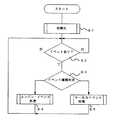
図8には、本発明による画像形成装置ネットワークシステムの一実施形態のメインフローのフローチャートが示されている。
連結された画像形成装置(図9参照。以下、装置という)のうちのある一台のトナー残量状態は、オンラインで他の装置に通知される。そして、トナーエンドが通知された場合には(ステップS11)、トナーエンドエンド情報を元に印刷可能な印刷色が表示手段に表示される(ステップS12)。ユーザは、かかる表示に応じて操作手段により、印刷可能な印刷色内で印刷色を指定した後に(ステップS13)、コピーをスタートする(ステップS14)。印刷中の装置において、印刷に必要なトナーがなくなったら、その装置における印刷は中止され、他の装置によって、残り分が印刷される(ステップS15)。
【0051】
上記実施形態について以下さらに具体的に説明する。
【0052】
子機のトナー残量が変化するたびに親機または他の子機に通知される。例えば、子機のマゼンタがなくなった場合は、フルカラーモード、ACSモード、2色コピーの赤/黒、単色赤、マゼンダの指定ができなくなる。そこで、2色モードの青/黒モードを指定して連結機能を使って印刷をする。そして、印刷中に、子機のシアントナーがトナーエンドになった際は子機の印刷動作を中止し、残りの印刷は他の子機または親機で行う。
【0053】
トナーエンドになった場合に連結された他の装置に伝送(通知)される情報には、他に給紙段情報や残紙情報も含むことができる。このような機器情報は、ある親機から常にポーリングで問い合わせる方式や各装置にてステータスが変化するたびに通知する方式により伝送される。これは、後述するコピー動作の中止状態や残部数の通知についても同様である。
もっとも、本発明はかかる方式によるものに限定されるものではない。
【0054】
このようにして子機のトナーエンド情報を得た親機または他の子機は、当該子機の残り部数の情報も同様にして得て、子機の残り部数をコピーする。
【0055】
印刷動作の中止と残内容の印刷の構成例としては、以下の2とおりが考えられる。
第1の構成例は次のとおりである。
まず、子機が、コピー動作を中止し、中止状態を親機に通知する。これを受けて、親機は、ユーザにアラート通知をする。これに応じて、ユーザは、親機にて子機にトナーを補給し再開させるか、親機への残部数分をコピーさせるかを選択する。(アラート通知および選択操作は、子機またはPC上のいずれで行われてもよい。)この構成例は、残部数のコピー動作がユーザにゆだねられることが特徴といえる。
第2の構成例は次のとおりである。
まず、子機は、コピーを停止し、親機に停止と残部数を通知する。これを受けて、親機または他の子機が、残部数を自動的にコピーする。すなわち、親機は、子機の残部数分を追加してコピーするか、コピー可能な子機を探して、その子機にコピーを指示する。この構成例は、残部数が自動的にコピーされることが特徴といえる。
【0056】
なお、上記2つの構成例は、子機がトナーエンドで停止した場合を想定しているが、親機がトナーエンドになった場合には、子機が親機のように振舞うことにより同様のことが可能となる。また、そもそも本発明は、上記構成例に限定されるものではなく、他の構成例にも適用される。
【0057】
以上のようにして、トナーエンドになった現像機を使用する印刷色による印刷を中止することにより、装置の品質のダウンを防止できる。また、他の装置に残印刷内容を印刷させることにより、ユーザは、トナーを補給したり、他の装置により原稿の読み取りを再度行ったりする手間が省ける。また、ユーザは、印刷色を指定することにより、当初の印刷色が途中で変わってしまうことを防ぐことができる。
【0058】
印刷可能な印刷色の表示手段と、印刷色の指定などの操作手段は、図2の操作部30上の何処か、または、図3の液晶タッチパネルないし外付けの操作部上に設けられることが可能である。もっとも、コピー機の操作部には種々の制約がある。そこで、ネットワーク経由にてPC上で連結コピーなどの操作ができるようにする構成も考えられる。例えば、図9には、Adobe社のPhotoshopにてリコーのスキャナにて読み込む際のPC上の画面が示されているが、このような画面上に印刷可能な印刷色などの情報が表示されるようにして、PCの操作により印刷色の指定などの作業ができるようにすることも可能である。こうすれば、作業状況がわかりやすくユーザにとって使い勝手がより良くなる。ただし、本発明における表示手段と操作手段は、以上の構成例に限定されるものではない。
【0059】
さらに、印刷中に子機が切り替わったことを親機にて表示させれば、出力先が追加されたことが直ちにわかり、ユーザは、どこにコピーが出力されたかを容易に知ることができる。さらに、トナーエンドとなった子機や残印刷を割り当てられた子機にも同様の表示をさせるという構成も可能である。すなわち、印刷中に子機が切り替わったことを当該子機または残印刷を割り当てられた子機においても表示させる構成である。要するに、印刷中に子機が切り替わったことを表示する手段については特に制約はないということである。
【0060】
なお、本実施例における装置の連結手段としては、基本的にはLANが予定されているが、本発明は、これに限定されるものではなく、WANなどの他のネットワークやインターネットにより装置が連結された場合にも適用可能である。
【0061】
以下、図10と図11を用いて、本発明による画像形成装置ネットワークシステムの一実施形態における使用装置の選択について説明する。
【0062】
図10には、本発明による画像形成装置ネットワークシステムの一例の概略図が示されている。ここでは、A、B、C、D、Eの5台の装置が連結されている。
【0063】
その中から、例えば、Eという装置で、操作を行ったとする。この場合、何も設定せずに、連結コピーを実行すると、A、B、C、D、E全てが動作してしまう。また、図10においては各装置は近くに設置されているように見えるが、 各装置が実際に設置されている場所は、 物理的に遠く離れている場合もあり、フロアが違う可能性さえもある。そのように装置間が離れている場合、ユーザとしては、自己の近くの何台かだけを連結動作させたいと考えるのが通常である。
【0064】
そこで、例えば、ユーザが、装置C、D、Eのみで連結させたい場合、図11に示されたフローチャートに従って、Eの操作パネルにて、連結可能な装置リストを表示させる(ステップS21)。すると、A、B、C、Dが操作パネル上にあらわれる。この中から、ユーザは、今回のジョブで使用したい装置であるC、Dのみを選択する(ステップS22)。この時に、選択された装置C、D各々の操作パネル上に、「連結選択」されたことの表示がされる。さらに、選択された装置C、Dより、ブザー音で、「連結選択」されたことユーザにを知らせるという構成も可能である。
【0065】
なお、上記操作パネルは、印刷可能な印刷色の表示や印刷色の指定のところで述べたのと同様、図2と図3に示した操作部30ないし外付けの操作部上に設けられても、図 に示したようなPC上の画面上に設けられてもよいが、これらの方式に限定されるものではなく、他の方式であってもよい。
【0066】
また、連結I/F汎用インターフェースであるIEEE1394またはEthernet(登録商標)を使用することにより、上述の効果が得られるが、これらに限定されるものではない。
【0067】
【発明の効果】
本発明によれば、連結された各画像形成装置のトナー残量状態に応じて、印刷色の決定や印刷動作の割り当てを適宜行えるので、ユーザの作業効率を向上させることができると同時に、画像の保証もできる。
【0068】
本発明によれば、連結された各画像形成装置のトナー残量情報を元に可能な印刷色のみを用いて印刷することが可能となるので、ユーザの作業効率を向上させることができ、画像の保証も図れる。
【0069】
本発明によれば、連結状態で印刷中に親機、子機のいずれかがトナーエンドになった印刷を中断した場合に残りの印刷を別の装置で行えるので、ユーザの作業効率を向上させることができ、画像の保証も図れる。
【0070】
本発明によれば、ユーザは出力先の追加と追加出力される場所が容易にわかるので、ユーザの作業効率をさらに向上させることができる。
【0071】
本発明によれば、ユーザは追加して出力できる場所を事前に知ることができるので、ユーザの作業効率をさらに向上させることができる。
【0072】
本発明によれば、ユーザは追加して出力される場所を諸事情に応じて自由に選択できるので、ユーザの作業効率をさらに向上させることができる。
【0073】
本発明によれば、ユーザは自己が選択した出力先を容易に知ることができるので、ユーザの作業効率をさらに向上させることができる。
【図面の簡単な説明】
【図1】本発明による画像形成装置及び画像形成装置ネットワークシステムの一実施形態における画像形成装置(複写機)の概略図である。
【図2】本発明による画像形成装置及び画像形成装置ネットワークシステムの一実施形態における操作部の平面図である。
【図3】本発明による画像形成装置及び画像形成装置ネットワークシステムの一実施形態における操作部内の液晶タッチパネルの説明図である。
【図4】本発明による画像形成装置及び画像形成装置ネットワークシステムの一実施形態における制御装置の構成図である。
【図5】本発明による画像形成装置及び画像形成装置ネットワークシステムの一実施形態における画像処理ユニット(IPU)のブロック図である。
【図6】本発明による画像形成装置及び画像形成装置ネットワークシステムの一実施形態におけるセレクタにおける画像信号の説明図である。
【図7】本発明による画像形成装置及び画像形成装置ネットワークシステムの一実施形態におけるイベント処理のフローチャートである。
【図8】本発明による画像形成装置及び画像形成装置ネットワークシステムの一実施形態のメインフローチャートである。
【図9】本発明による画像形成装置及び画像形成装置ネットワークシステムの一実施形態の説明図である。
【図10】本発明による画像形成装置及び画像形成装置ネットワークシステムの一実施形態の概略図である。
【図11】本発明による画像形成装置及び画像形成装置ネットワークシステムの一実施形態における使用装置選択処理のフローチャートである。
【符号の説明】
1 自動原稿送り装置(ADF)
2 原稿台
3 給送ローラ
4 給送ベルト
5 排送ローラ
6 コンタクトガラス
7 原稿セット検知
8 第1トレイ
9 第2トレイ
10 第3トレイ
11 第1給紙装置
12 第2給紙装置
13 第3給紙装置
14 縦搬送ユニット
15 感光体
16 搬送ベルト
17 定着ユニット
18 排紙ユニット
19 排紙トレイ
20 メインコントローラ
21 中間クラッチ
22 第1給紙クラッチ
23 第2給紙クラッチ
24 第3給紙クラッチ
25 メインモータ
26 搬送モータ
27 現像ユニット
30 操作部
31 液晶タッチパネル
32 テンキー
33 クリア/ストップキー
34 プリントキー(スタートキー)
35 モードクリアキー
36 初期設定キー
48 連結I/F
49 画像処理ユニット(IPU)
50 読み取りユニット
51 露光ランプ
52 第1ミラー
53 レンズ
54 CCDイメージセンサ
55 第2ミラー
56 第3ミラー
57 書き込みユニット
58 レーザ出力ユニット
59 結像レンズ
60 ミラー
61 A/Dコンバータ
62 シェーディング補正
63 画像処理部
64 セレクタ
65 画像メモリコントローラ
66 画像メモリ
67 I/Oポート
68 CPU
69 ROM
70 RAM
71 書き込み補正γ訂正
72 変倍処理[0001]
BACKGROUND OF THE INVENTION
The present inventionImage forming apparatus network system, image forming apparatus, control method, and control programIn particular, image data is transferred between two or more image forming apparatuses (digital copying machines) having an image forming mechanism of two or more colors.Image forming apparatus network system, image forming apparatus, control method, and control programAbout.
[0002]
[Prior art]
Conventionally, there has been a network system in which two or more image forming apparatuses are connected. As such a system, for example, an image forming apparatus connection system described in Japanese Patent Laid-Open No. 2001-100756 has been known. This system is designed to improve the use efficiency of the storage device by detecting the use state of the storage device of each image forming apparatus and appropriately assigning the storage device used for the job.
[0003]
[Problems to be solved by the invention]
However, even in such a system, when the image forming apparatus is a color machine, there remains a problem of detecting in-machine information (particularly toner information) between the connected image forming apparatuses. That is, it is known that in a color machine, the printable print color changes when there is no specific toner. Printing can also be performed between connected image forming apparatuses depending on the remaining amount of toner in an image forming apparatus (hereinafter referred to as a slave unit) connected to an image forming apparatus (hereinafter referred to as a master unit) for setting each mode or connection. The printing color is different. Therefore, depending on the remaining amount of toner, the color uniformity after printing may not be maintained. For example, when the near end is reached during printing, printing continues until the apparatus is stopped due to the toner end, so the color of the printed product may be different at the beginning and at the end. In particular, such a situation is likely to occur in the case of mass copying by a trader, and if such a situation actually occurs, the customer or the trader may be burdened with extra effort and cost.
[0004]
Therefore, according to the present invention, it is possible to improve the user's work efficiency by appropriately determining the printing color and assigning the printing operation according to the toner remaining state of each connected image forming apparatus. In addition, the uniformity of the printed image can be guaranteed (hereinafter referred to as image guarantee).Image forming apparatus network system, image forming apparatus, control method, and control programThe purpose is to provide.
[0005]
[Means for Solving the Problems]
In order to achieve this object, the present invention has the following features.
[0006]
An image forming apparatus network system according to the present invention includes:
An image forming apparatus network system connecting a plurality of image forming apparatuses,
In each image forming deviceEach colorToner remaining status,Notify other connected image forming apparatusesnotificationMeans and,
In accordance with the toner remaining state of each color of each image forming apparatus notified by the notification means, a print color is designated within the print colors that can be printed in the image forming apparatus that performs concatenated copying, and the specified print color is connected. Connecting operation means for performing copying;
In the image forming apparatus that has undergone linked copying by the linkage operation means, when the toner necessary for printing in the designated printing color reaches a toner end, a stopping means for stopping printing in the printing color;It is characterized by having.
[0007]
An image forming apparatus network system according to the present invention includes:
And an allocating unit that allocates the remaining print contents to the other image forming apparatus when the printing by the printing unit is stopped by the canceling unit.
[0008]
Further, the image forming apparatus according to the present invention includes:
An image forming apparatus on the master side constituting an image forming apparatus network system in which a plurality of image forming apparatuses are connected,
The toner remaining state of each color in each image forming apparatus is acquired, and the print color within the print colors that can be printed in the image forming apparatus that performs linked copying according to the acquired toner remaining state of each color of each image forming apparatus Linking operation means for linking and copying with the specified printing color;
In the master-side image forming apparatus that has undergone linked copying by the linkage operation means, when the toner necessary for printing in the designated printing color reaches a toner end, printing in the printing color is stopped. And a canceling means.
[0009]
Further, the image forming apparatus according to the present invention includes:
And an allocating unit that allocates the remaining print contents to the other image forming apparatus when the printing by the printing unit is stopped by the canceling unit.
[0010]
Further, the image forming apparatus according to the present invention includes:
In the slave-side image forming apparatus that has undergone linked copying by the linkage operation means, the toner necessary for printing in the designated printing color becomes a toner end, and printing in the printing color is performed on the slave-side image. And an allocating unit for allocating the remaining print contents to the other image forming apparatuses when the forming apparatus cancels and accepts the canceled state and the remaining print contents from the image forming apparatus on the slave side.
[0011]
Further, the image forming apparatus according to the present invention includes:
An image forming apparatus on a slave side constituting an image forming apparatus network system in which a plurality of image forming apparatuses are connected,
Notification means for notifying other connected image forming apparatuses of the remaining amount of toner for each color in the slave-side image forming apparatus;
A connection operation means for performing connection copying with a print color designated according to the remaining amount of toner of each color from the image forming apparatus on the master side;
In the slave-side image forming apparatus that has undergone linked copying by the linkage operation means, when the toner necessary for printing in the designated printing color reaches the toner end, printing in the printing color is stopped. And a canceling means.
[0012]
Further, the image forming apparatus according to the present invention includes:
And a notification unit that notifies the image forming apparatus on the master side of the cancellation state and the remaining print contents when printing in the print color is stopped by the cancellation unit.
[0013]
Further, the control method according to the present invention includes:
A control method performed by an image forming apparatus on a master side constituting an image forming apparatus network system in which a plurality of image forming apparatuses are connected,
The toner remaining state of each color in each image forming apparatus is acquired, and the print color within the print colors that can be printed in the image forming apparatus that performs linked copying according to the acquired toner remaining state of each color of each image forming apparatus And a connecting operation step of performing linked copying with the specified printing color;
In the master-side image forming apparatus that has undergone linked copying in the linked operation step, printing in the print color is stopped when the toner necessary for printing in the designated print color reaches a toner end. The stopping process is performed by the image forming apparatus on the master side.
Further, the control method according to the present invention includes:
A control method performed by a slave-side image forming apparatus constituting an image forming apparatus network system in which a plurality of image forming apparatuses are connected,
A notification step of notifying other connected image forming apparatuses of the remaining amount of toner of each color in the image forming apparatus on the slave side;
A concatenation operation step of performing concatenated copying with a printing color designated according to the remaining amount of toner of each color from the image forming apparatus on the master side;
In the slave-side image forming apparatus that has undergone linked copying in the linked operation step, when the toner necessary for printing in the designated printing color reaches the toner end, printing in the printed color is stopped. The stopping process is performed by the slave-side image forming apparatus.
[0014]
Further, the control program according to the present invention is:
A control program to be executed by a master image forming apparatus constituting an image forming apparatus network system in which a plurality of image forming apparatuses are connected,
The toner remaining state of each color in each image forming apparatus is acquired, and the print color within the print colors that can be printed in the image forming apparatus that performs linked copying according to the acquired toner remaining state of each color of each image forming apparatus Linking operation processing for linking and copying with the specified printing color;
In the master-side image forming apparatus that has undergone linked copying by the linkage operation processing, printing in the printing color is stopped when the toner necessary for printing in the designated printing color reaches a toner end. The stop processing is executed by the image forming apparatus on the master side.
Further, the control program according to the present invention is:
A control program to be executed by a slave-side image forming apparatus constituting an image forming apparatus network system in which a plurality of image forming apparatuses are connected,
A notification process for notifying other connected image forming apparatuses of the remaining amount of toner for each color in the image forming apparatus on the slave side;
A concatenation operation process for performing concatenated copying in a print color designated according to the remaining toner state of each color from the image forming apparatus on the master side;
In the slave-side image forming apparatus that has undergone linked copying as a result of the linked operation processing, printing in the print color is stopped when the toner necessary for printing in the designated print color reaches a toner end. The stop processing is executed by the image forming apparatus on the slave side.
[0015]
DETAILED DESCRIPTION OF THE INVENTION
Embodiments of an image forming apparatus and an image forming apparatus network system according to the present invention will be described below in detail with reference to the accompanying drawings.
[0016]
First, an image forming apparatus and an image forming apparatus according to an embodiment of the present invention will be described with reference to FIGS.
[0017]
FIG. 1 shows a schematic diagram of an entire image forming apparatus (copier) in an embodiment of an image forming apparatus and an image forming apparatus network system according to the present invention.
[0018]
A document bundle placed on a document table 2 with an image surface facing up in an automatic document feeder (hereinafter referred to as ADF) 1 is a start key (print) on the
[0019]
The image data of the document fed on the
[0020]
Further, when it is detected by the document set
[0021]
The transfer sheets stacked on the
[0022]
The image data read by the
[0023]
When forming an image on both sides of the transfer paper, the transfer paper fed from each of the
[0024]
When the transfer sheet is reversed and discharged, the sheet switchback reversed by the reversing unit 112 as described above is sent to the reverse discharge conveyance path 114 without being sent to the duplex conveying unit 111 and discharged.
[0025]
The
[0026]
FIG. 2 shows an
[0027]
The
[0028]
FIG. 3 shows a display example of the liquid
[0029]
When the operator touches a key displayed on the liquid
[0030]
FIG. 3 shows an example of a display unit for setting whether to transmit / receive information to / from a connected image forming apparatus. In this case, for example, by touching a “link” key, setting of a link operation using a plurality of connected image forming apparatuses is selected. Then, as described later, the own machine requests the image forming apparatus (slave machine) other than the connected own machine as a master machine for the linked operation.
[0031]
FIG. 4 shows the configuration of a control device centering on the main controller of the image forming apparatus in an embodiment of the image forming apparatus and the image forming apparatus network system according to the present invention. An
[0032]
The
[0033]
Further, the connection I /
[0034]
With reference to the drawings described above, the operation from reading an original to writing an image in the image forming apparatus according to an embodiment of the image forming apparatus and the image forming apparatus network system according to the present invention will be described below.
[0035]
The
[0036]
The exposure lamp 51 and the first mirror 52 are fixed on a first carriage (not shown), and the
The document image is read by the
[0037]
The writing unit 57 includes a laser output unit 58, an imaging lens 59, and a mirror 60. Inside the laser output unit 58 is a polygon that rotates at a constant speed at high speed by a laser diode and a motor that are laser light sources. A mirror (polygon mirror) is provided.
[0038]
The laser beam output from the writing unit 57 is applied to the
[0039]
FIG. 5 is a block diagram showing an internal configuration of an image processing unit (IPU) 49 in an embodiment of the image forming apparatus network system according to the present invention.
[0040]
The reflection of light emitted from the exposure lamp 51 in FIG. 1 is photoelectrically converted by the
[0041]
The image processing unit (IPU) 49 includes a
[0042]
The connection I /
With the above-described configuration, it is possible to realize the connecting operation without being restricted by the function of the image forming apparatus.
[0043]
The image sent to the image memory controller 65 as a document image is sent to the image memory 66 after the image data is compressed by an image compression device in the image memory controller 65. Here, the reason for compressing the image is as follows.
Although it is possible to directly write 256 gradation data corresponding to the maximum image size to the image memory 66, the image memory is very much used for one original image. By performing image compression, a limited image memory can be used effectively. In addition, since a large amount of original image data can be stored at one time, the stored original image data can be output in page order as a sorting function. In this case, when the image is output, the data in the image memory 66 is output while being sequentially expanded by the expansion device in the image memory controller 65. Such a function is generally called “electronic sort”.
Further, by using the function of the image memory, it is possible to sequentially read a plurality of document images into an area obtained by dividing the area of one transfer sheet of the image memory. For example, four original images are sequentially written into an area divided into four equal parts for one transfer paper in the image memory, and the four copy originals are combined into a single transfer paper image to produce a consolidated copy output. Can be obtained. Such a function is generally called “aggregate copy”.
[0044]
The image in the image memory 66 is configured to be accessible from the
[0045]
As the image memory 66, a hard disk may be used to store a lot of image data. By using a hard disk, there is a feature that an external power source is unnecessary and an image can be retained permanently. In order to read and hold a plurality of standard documents (format documents) with a scanner, this hard disk is generally used.
[0046]
Here, an image signal for one page in the selector 64 will be described with reference to FIG.
/ FGATE represents a valid period in the sub-scanning direction of one page of image data. / LSYNC is a main scanning synchronization signal for each line, and the image signal becomes valid at a predetermined clock after this signal rises. A signal indicating that the image signal in the main scanning direction is valid is / LGATE. These signals are synchronized with the pixel clock VCLK, and data of 8 bits per pixel (256 gradations) is sent for one cycle of VCLK. In this embodiment, it is assumed that the closer the image data is to 255, the more white the image is.
[0047]
Based on the above, the operation of an embodiment of an image forming apparatus and an image forming apparatus network system according to the present invention will be described below.
[0048]
First, event processing in an embodiment of the image forming apparatus network system according to the present invention will be described with reference to the flowchart of FIG.
When the power is turned on, an initialization process is first performed (step S1).
The main contents of initialization are resetting various flags, clearing various counters, clearing an image memory, resetting an image forming mode (magnification, division, etc.), and the like. (The initialization flow is not shown.)
After completion of initialization, the process waits for an input from the key input or the image forming engine (any change factor) (step S2). When the user performs any key operation, the
In step S3, it is determined whether the generated event is a key input or an engine. In the case of the engine, the engine event process (step S4) is called. In the case of key input, the key input event process (step S5) is called, and the process waits for the event in step S2 again.
[0049]
Next, the overall operation of an embodiment of the image forming apparatus and the image forming apparatus network system according to the present invention will be described.
[0050]
FIG. 8 shows a flowchart of the main flow of an embodiment of the image forming apparatus network system according to the present invention.
The remaining toner level of one of the connected image forming apparatuses (see FIG. 9; hereinafter referred to as “apparatus”) is notified to other apparatuses online. When the toner end is notified (step S11), a printable print color is displayed on the display unit based on the toner end-end information (step S12). In response to the display, the user designates a print color within the printable print colors using the operation means (step S13), and then starts copying (step S14). When there is no toner necessary for printing in the printing apparatus, printing in the printing apparatus is stopped, and the remaining part is printed by another apparatus (step S15).
[0051]
The above embodiment will be described more specifically below.
[0052]
Whenever the remaining amount of toner in the slave unit changes, the master unit or another slave unit is notified. For example, when there is no magenta of the slave unit, it is impossible to specify full color mode, ACS mode, two-color copy red / black, single color red, and magenta. Therefore, the blue / black mode of the two-color mode is designated and printing is performed using the connection function. During printing, when the cyan toner of the slave unit reaches the toner end, the printing operation of the slave unit is stopped, and the remaining printing is performed by another slave unit or the master unit.
[0053]
The information transmitted (notified) to other apparatuses connected when the toner end is reached can also include paper feed stage information and remaining paper information. Such device information is transmitted by a method that always inquires from a parent device by polling or a method that notifies each time the status changes in each device. The same applies to the notification of the copy operation cancellation status and the remaining number of copies, which will be described later.
However, the present invention is not limited to the above method.
[0054]
The master unit or other slave unit that has obtained the toner end information of the slave unit in this manner also obtains information on the remaining number of copies of the slave unit and copies the remaining number of copies of the slave unit.
[0055]
The following two examples are conceivable as a configuration example of canceling the printing operation and printing the remaining contents.
The first configuration example is as follows.
First, the slave unit stops the copy operation and notifies the master unit of the stop state. In response to this, the master unit notifies the user of an alert. In response to this, the user selects whether to replenish and restart the toner in the slave unit in the master unit or to copy the remaining number of copies to the master unit. (Alert notification and selection operation may be performed either on the slave unit or on the PC.) This configuration example is characterized in that the copy operation of the remaining number is left to the user.
The second configuration example is as follows.
First, the slave unit stops copying, and notifies the master unit of the stop and the remaining number of copies. In response, the parent device or other child device automatically copies the remaining number of copies. That is, the master unit adds and copies the remaining number of slave units, or searches for a slave unit that can be copied and instructs the slave unit to copy. This configuration example is characterized by the fact that the remaining number of copies is automatically copied.
[0056]
The above two configuration examples assume a case where the slave unit stops at the toner end. However, when the master unit becomes a toner end, the slave unit behaves like the master unit and is similar. It becomes possible. In the first place, the present invention is not limited to the above-described configuration example, but can be applied to other configuration examples.
[0057]
As described above, the quality of the apparatus can be prevented from being lowered by canceling the printing with the printing color using the developing machine that has become the toner end. In addition, by printing the remaining print contents on another device, the user can save time and effort for replenishing toner and reading the document again using another device. In addition, the user can prevent the original print color from being changed midway by designating the print color.
[0058]
Printable print color display means and operation means such as print color designation may be provided somewhere on the
[0059]
Furthermore, if the parent device displays that the child device has been switched during printing, it can be immediately recognized that the output destination has been added, and the user can easily know where the copy has been output. Further, it is possible to make a similar display on a slave unit that has become a toner end or a slave unit to which remaining printing is assigned. In other words, this is a configuration in which the slave device or the slave device to which the remaining printing is assigned is displayed to indicate that the slave device has been switched during printing. In short, there is no particular restriction on the means for displaying that the slave unit has been switched during printing.
[0060]
Note that a LAN is basically planned as a device connection unit in this embodiment, but the present invention is not limited to this, and the device is connected by another network such as a WAN or the Internet. It is also possible to apply it.
[0061]
Hereinafter, selection of a device to be used in an embodiment of the image forming apparatus network system according to the present invention will be described with reference to FIGS. 10 and 11.
[0062]
FIG. 10 shows a schematic diagram of an example of an image forming apparatus network system according to the present invention. Here, five devices A, B, C, D, and E are connected.
[0063]
For example, it is assumed that an operation is performed with an apparatus E. In this case, if concatenated copying is executed without setting anything, all of A, B, C, D, and E operate. Also, in Fig. 10, each device appears to be installed nearby, but the location where each device is actually installed may be physically far away, and even the floor may be different. is there. In such a case where the devices are separated from each other, the user normally wants to connect only a few units near him.
[0064]
Therefore, for example, when the user wants to connect only with the devices C, D, and E, according to the flowchart shown in FIG. 11, a list of devices that can be connected is displayed on the operation panel of E (step S21). Then, A, B, C, and D appear on the operation panel. Among these, the user selects only C and D, which are apparatuses that are desired to be used in the current job (step S22). At this time, an indication that “connected” has been selected is displayed on the operation panel of each of the selected devices C and D. Further, it is also possible to notify the user that “connection selection” has been made by a buzzer sound from the selected devices C and D.
[0065]
The operation panel may be provided on the
[0066]
Moreover, although the above-mentioned effect is acquired by using IEEE1394 or Ethernet (registered trademark) which is a general-purpose I / F interface, the present invention is not limited to these.
[0067]
【The invention's effect】
According to the present invention, it is possible to appropriately determine the printing color and assign the printing operation in accordance with the toner remaining state of each of the connected image forming apparatuses. Can also guarantee.
[0068]
The present inventionAccordingly, it is possible to perform printing using only possible print colors based on the remaining toner information of the connected image forming apparatuses, so that the user's work efficiency can be improved and the image can be guaranteed. Can also be planned.
[0069]
The present inventionAccording to the above, either the master unit or the slave unit becomes a toner end during printing in the connected state.TheWhen printing is interrupted, the remaining printing can be performed by another apparatus, so that the user's work efficiency can be improved and the image can be guaranteed.
[0070]
The present inventionAccording to this, since the user can easily know the addition of the output destination and the location where the output is additionally output, the user's work efficiency can be further improved.
[0071]
The present inventionAccording to this, since the user can know in advance the place where the user can additionally output, the user's work efficiency can be further improved.
[0072]
The present inventionAccording to this, the user can freely select a place to be additionally output according to various circumstances, so that the user's work efficiency can be further improved.
[0073]
The present inventionSince the user can easily know the output destination selected by the user, the user's work efficiency can be further improved.
[Brief description of the drawings]
FIG. 1 is a schematic diagram of an image forming apparatus (copier) in an embodiment of an image forming apparatus and an image forming apparatus network system according to the present invention.
FIG. 2 is a plan view of an operation unit in an embodiment of an image forming apparatus and an image forming apparatus network system according to the present invention.
FIG. 3 is an explanatory diagram of a liquid crystal touch panel in an operation unit in an embodiment of an image forming apparatus and an image forming apparatus network system according to the present invention.
FIG. 4 is a configuration diagram of a control device in an embodiment of an image forming apparatus and an image forming apparatus network system according to the present invention.
FIG. 5 is a block diagram of an image processing unit (IPU) in an embodiment of an image forming apparatus and an image forming apparatus network system according to the present invention.
FIG. 6 is an explanatory diagram of an image signal in a selector in an embodiment of an image forming apparatus and an image forming apparatus network system according to the present invention.
FIG. 7 is a flowchart of event processing in an embodiment of an image forming apparatus and an image forming apparatus network system according to the present invention.
FIG. 8 is a main flowchart of an embodiment of an image forming apparatus and an image forming apparatus network system according to the present invention.
FIG. 9 is an explanatory diagram of an embodiment of an image forming apparatus and an image forming apparatus network system according to the present invention.
FIG. 10 is a schematic diagram of an embodiment of an image forming apparatus and an image forming apparatus network system according to the present invention.
FIG. 11 is a flowchart of a device selection process in an embodiment of an image forming apparatus and an image forming apparatus network system according to the present invention.
[Explanation of symbols]
1 Automatic document feeder (ADF)
2 Document table
3 Feeding roller
4 Feeding belt
5 Discharge roller
6 Contact glass
7 Document set detection
8 First tray
9 Second tray
10 Third tray
11 First paper feeder
12 Second paper feeder
13 Third paper feeder
14 Vertical transport unit
15 photoconductor
16 Conveyor belt
17 Fixing unit
18 Paper discharge unit
19 Output tray
20 Main controller
21 Intermediate clutch
22 First feed clutch
23 Second paper feed clutch
24 Third paper feed clutch
25 Main motor
26 Conveyor motor
27 Development unit
30 Operation unit
31 LCD touch panel
32 numeric keypad
33 Clear / Stop key
34 Print key (Start key)
35 Mode clear key
36 Initial setting key
48 Linked I / F
49 Image processing unit (IPU)
50 reading unit
51 Exposure lamp
52 First mirror
53 lenses
54 CCD image sensor
55 Second mirror
56 Third mirror
57 Writing unit
58 Laser output unit
59 Imaging lens
60 mirror
61 A / D converter
62 Shading correction
63 Image processing unit
64 selector
65 Image memory controller
66 Image memory
67 I / O port
68 CPU
69 ROM
70 RAM
71 Write correction γ correction
72 Scaling processing
Claims (11)
Translated fromJapanese各画像形成装置における各色のトナー残量状態を、連結された他の前記画像形成装置に通知する通知手段と、
前記通知手段により通知された各画像形成装置の各色のトナー残量状態に応じて、連結複写を行う画像形成装置において印刷可能な印刷色内で印刷色を指定し、該指定した印刷色で連結複写を行う連結動作手段と、
前記連結動作手段により連結複写中となった画像形成装置において、前記指定した印刷色での印刷に必要なトナーがトナーエンドになった場合に、前記印刷色での印刷を中止する中止手段と、を有することを特徴とする画像形成装置ネットワークシステム。An image forming apparatus network system connecting a plurality of image forming apparatuses,
Thecolor toner remaining amount status conditionof the respective image formingapparatuses, anotification unit for notifying other of the image forming apparatusconnected,
In accordance with the toner remaining state of each color of each image forming apparatus notified by the notification means, a print color is designated within the print colors that can be printed in the image forming apparatus that performs concatenated copying, and the specified print color is connected. Connecting operation means for performing copying;
In the image forming apparatus that has undergone linked copying by the linkage operation means, when the toner necessary for printing in the designated printing color reaches a toner end, a stopping means for stopping printing in the printing color; An image forming apparatus network system comprising:
各画像形成装置における各色のトナー残量状態を取得し、該取得した各画像形成装置の各色のトナー残量状態に応じて、連結複写を行う画像形成装置において印刷可能な印刷色内で印刷色を指定し、該指定した印刷色で連結複写を行う連結動作手段と、 The toner remaining state of each color in each image forming apparatus is acquired, and the print color within the print colors that can be printed in the image forming apparatus that performs linked copying according to the acquired toner remaining state of each color of each image forming apparatus Linking operation means for linking and copying with the specified printing color;
前記連結動作手段により連結複写中となった前記マスタ側の画像形成装置において、前記指定した印刷色での印刷に必要なトナーがトナーエンドになった場合に、前記印刷色での印刷を中止する中止手段と、を有することを特徴とする画像形成装置。 In the master-side image forming apparatus that has undergone linked copying by the linkage operation means, when the toner necessary for printing in the designated printing color reaches a toner end, printing in the printing color is stopped. An image forming apparatus comprising: a canceling unit;
前記スレーブ側の画像形成装置における各色のトナー残量状態を、連結された他の画像形成装置に通知する通知手段と、
マスタ側の画像形成装置から前記各色のトナー残量状態に応じて指定された印刷色で連結複写を行う連結動作手段と、
前記連結動作手段により連結複写中となった前記スレーブ側の画像形成装置において、前記指定された印刷色での印刷に必要なトナーがトナーエンドになった場合に、前記印刷色での印刷を中止する中止手段と、を有することを特徴とする画像形成装置。An image forming apparatus ona slave side constituting an image forming apparatus network system in which a plurality of image forming apparatuses are connected,
Notification means for notifying other connected image forming apparatuses of the remaining amount of toner for each color in the slave-side image forming apparatus;
A connection operation means for performing connection copying with a print color designated according to the remaining amount of toner of each color from the image forming apparatus on the master side;
In the slave-side image forming apparatus that has undergone linked copying by the linkage operation means, when the toner necessary for printing in the designated printing color reaches the toner end, printing in the printing color is stopped. An image forming apparatus comprising: an suspending unit for stopping the image.
各画像形成装置における各色のトナー残量状態を取得し、該取得した各画像形成装置の各色のトナー残量状態に応じて、連結複写を行う画像形成装置において印刷可能な印刷色内で印刷色を指定し、該指定した印刷色で連結複写を行う連結動作工程と、 The toner remaining state of each color in each image forming apparatus is acquired, and the print color within the print colors that can be printed in the image forming apparatus that performs linked copying according to the acquired toner remaining state of each color of each image forming apparatus And a connecting operation step of connecting and copying with the specified printing color;
前記連結動作工程により連結複写中となった前記マスタ側の画像形成装置において、前記指定した印刷色での印刷に必要なトナーがトナーエンドになった場合に、前記印刷色で In the master-side image forming apparatus that has undergone linked copying in the linked operation step, when the toner required for printing in the designated print color reaches the toner end, the print color isの印刷を中止する中止工程と、を前記マスタ側の画像形成装置が行うことを特徴とする制御方法。A control method characterized in that the master side image forming apparatus performs a canceling step of canceling printing.
前記スレーブ側の画像形成装置における各色のトナー残量状態を、連結された他の画像形成装置に通知する通知工程と、 A notification step of notifying other connected image forming apparatuses of the remaining amount of toner of each color in the image forming apparatus on the slave side;
マスタ側の画像形成装置から前記各色のトナー残量状態に応じて指定された印刷色で連結複写を行う連結動作工程と、 A concatenation operation step of performing concatenation copying with a printing color designated according to the remaining amount of toner of each color from the image forming apparatus on the master side;
前記連結動作工程により連結複写中となった前記スレーブ側の画像形成装置において、前記指定された印刷色での印刷に必要なトナーがトナーエンドになった場合に、前記印刷色での印刷を中止する中止工程と、を、前記スレーブ側の画像形成装置が行うことを特徴とする制御方法。 In the slave-side image forming apparatus that has undergone linked copying in the linked operation step, when the toner required for printing in the designated printing color reaches the toner end, printing in the printed color is stopped. A control step, wherein the slave-side image forming apparatus performs the canceling step.
各画像形成装置における各色のトナー残量状態を取得し、該取得した各画像形成装置の各色のトナー残量状態に応じて、連結複写を行う画像形成装置において印刷可能な印刷色内で印刷色を指定し、該指定した印刷色で連結複写を行う連結動作処理と、 The toner remaining state of each color in each image forming apparatus is acquired, and the print color within the print colors that can be printed in the image forming apparatus that performs linked copying according to the acquired toner remaining state of each color of each image forming apparatus Linking operation processing for linking and copying with the specified printing color;
前記連結動作処理により連結複写中となった前記マスタ側の画像形成装置において、前記指定した印刷色での印刷に必要なトナーがトナーエンドになった場合に、前記印刷色での印刷を中止する中止処理と、を前記マスタ側の画像形成装置に実行させることを特徴とする制御プログラム。 In the master-side image forming apparatus that has undergone linked copying by the linkage operation processing, printing in the printing color is stopped when the toner necessary for printing in the designated printing color reaches a toner end. A control program that causes the image forming apparatus on the master side to execute a cancellation process.
前記スレーブ側の画像形成装置における各色のトナー残量状態を、連結された他の画像形成装置に通知する通知処理と、 A notification process for notifying other connected image forming apparatuses of the remaining amount of toner for each color in the image forming apparatus on the slave side;
マスタ側の画像形成装置から前記各色のトナー残量状態に応じて指定された印刷色で連結複写を行う連結動作処理と、 A concatenation operation process for performing concatenated copying in a print color designated according to the remaining toner state of each color from the image forming apparatus on the master side;
前記連結動作処理により連結複写中となった前記スレーブ側の画像形成装置において、前記指定された印刷色での印刷に必要なトナーがトナーエンドになった場合に、前記印刷色での印刷を中止する中止処理と、を、前記スレーブ側の画像形成装置に実行させることを特徴とする制御プログラム。 In the slave-side image forming apparatus that has undergone linked copying as a result of the linked operation processing, printing in the print color is stopped when the toner necessary for printing in the designated print color reaches a toner end. A control program for causing the slave-side image forming apparatus to execute a canceling process.
Priority Applications (1)
| Application Number | Priority Date | Filing Date | Title |
|---|---|---|---|
| JP2002123147AJP4024585B2 (en) | 2002-04-24 | 2002-04-24 | Image forming apparatus network system, image forming apparatus, control method, and control program |
Applications Claiming Priority (1)
| Application Number | Priority Date | Filing Date | Title |
|---|---|---|---|
| JP2002123147AJP4024585B2 (en) | 2002-04-24 | 2002-04-24 | Image forming apparatus network system, image forming apparatus, control method, and control program |
Publications (2)
| Publication Number | Publication Date |
|---|---|
| JP2003316214A JP2003316214A (en) | 2003-11-07 |
| JP4024585B2true JP4024585B2 (en) | 2007-12-19 |
Family
ID=29538571
Family Applications (1)
| Application Number | Title | Priority Date | Filing Date |
|---|---|---|---|
| JP2002123147AExpired - Fee RelatedJP4024585B2 (en) | 2002-04-24 | 2002-04-24 | Image forming apparatus network system, image forming apparatus, control method, and control program |
Country Status (1)
| Country | Link |
|---|---|
| JP (1) | JP4024585B2 (en) |
- 2002
- 2002-04-24JPJP2002123147Apatent/JP4024585B2/ennot_activeExpired - Fee Related
Also Published As
| Publication number | Publication date |
|---|---|
| JP2003316214A (en) | 2003-11-07 |
Similar Documents
| Publication | Publication Date | Title |
|---|---|---|
| US7006249B2 (en) | Image forming system | |
| KR100738602B1 (en) | Imaging device, image processing device, image forming apparatus and image processing system | |
| JP2008003235A (en) | Image forming system, image forming apparatus, and control method thereof | |
| JP4562574B2 (en) | Tandem image forming apparatus | |
| JPH10257281A (en) | Image forming device | |
| JP2918784B2 (en) | Image processing apparatus and method | |
| JP4056402B2 (en) | Image forming apparatus network system, image forming apparatus, connection operation method, and program | |
| JP4024585B2 (en) | Image forming apparatus network system, image forming apparatus, control method, and control program | |
| JP3537612B2 (en) | Image forming system | |
| JP4023722B2 (en) | Image forming apparatus system and image forming apparatus | |
| JP2002199152A (en) | Network system having a plurality of imaging devices | |
| JP2000335057A (en) | Image forming system and method | |
| JP2005014247A (en) | Image forming apparatus | |
| JP3589547B2 (en) | Copying system | |
| JP2005191804A (en) | Image forming apparatus and image processing program | |
| JP2005349657A (en) | Image forming apparatus, use environment control method, program, and storage medium | |
| JP2005193394A (en) | Image forming apparatus, computer program, and recording medium | |
| JPH11231730A (en) | Image forming device | |
| JP2000181295A (en) | Image forming device | |
| JP2000203126A (en) | Image forming device | |
| JP2001103256A (en) | Image processing system | |
| JP2001022224A (en) | Image forming device | |
| JP2001013827A (en) | Image forming apparatus and image forming system | |
| JP2001100956A (en) | Image forming device connection system | |
| JPH10153928A (en) | Copier network system |
Legal Events
| Date | Code | Title | Description |
|---|---|---|---|
| A621 | Written request for application examination | Free format text:JAPANESE INTERMEDIATE CODE: A621 Effective date:20041208 | |
| RD02 | Notification of acceptance of power of attorney | Free format text:JAPANESE INTERMEDIATE CODE: A7422 Effective date:20050105 | |
| A131 | Notification of reasons for refusal | Free format text:JAPANESE INTERMEDIATE CODE: A131 Effective date:20070612 | |
| A521 | Written amendment | Free format text:JAPANESE INTERMEDIATE CODE: A523 Effective date:20070806 | |
| TRDD | Decision of grant or rejection written | ||
| A01 | Written decision to grant a patent or to grant a registration (utility model) | Free format text:JAPANESE INTERMEDIATE CODE: A01 Effective date:20070925 | |
| A61 | First payment of annual fees (during grant procedure) | Free format text:JAPANESE INTERMEDIATE CODE: A61 Effective date:20071003 | |
| R150 | Certificate of patent or registration of utility model | Free format text:JAPANESE INTERMEDIATE CODE: R150 | |
| FPAY | Renewal fee payment (event date is renewal date of database) | Free format text:PAYMENT UNTIL: 20101012 Year of fee payment:3 | |
| FPAY | Renewal fee payment (event date is renewal date of database) | Free format text:PAYMENT UNTIL: 20111012 Year of fee payment:4 | |
| FPAY | Renewal fee payment (event date is renewal date of database) | Free format text:PAYMENT UNTIL: 20121012 Year of fee payment:5 | |
| FPAY | Renewal fee payment (event date is renewal date of database) | Free format text:PAYMENT UNTIL: 20131012 Year of fee payment:6 | |
| LAPS | Cancellation because of no payment of annual fees |