JP4024394B2 - Paper processing device - Google Patents
Paper processing deviceDownload PDFInfo
- Publication number
- JP4024394B2 JP4024394B2JP22415898AJP22415898AJP4024394B2JP 4024394 B2JP4024394 B2JP 4024394B2JP 22415898 AJP22415898 AJP 22415898AJP 22415898 AJP22415898 AJP 22415898AJP 4024394 B2JP4024394 B2JP 4024394B2
- Authority
- JP
- Japan
- Prior art keywords
- paper
- sheet
- unit
- fed
- processing
- Prior art date
- Legal status (The legal status is an assumption and is not a legal conclusion. Google has not performed a legal analysis and makes no representation as to the accuracy of the status listed.)
- Expired - Fee Related
Links
Images


Classifications
- G—PHYSICS
- G03—PHOTOGRAPHY; CINEMATOGRAPHY; ANALOGOUS TECHNIQUES USING WAVES OTHER THAN OPTICAL WAVES; ELECTROGRAPHY; HOLOGRAPHY
- G03G—ELECTROGRAPHY; ELECTROPHOTOGRAPHY; MAGNETOGRAPHY
- G03G15/00—Apparatus for electrographic processes using a charge pattern
- G03G15/65—Apparatus which relate to the handling of copy material
- G03G15/6502—Supplying of sheet copy material; Cassettes therefor
- G03G15/6508—Automatic supply devices interacting with the rest of the apparatus, e.g. selection of a specific cassette
- B—PERFORMING OPERATIONS; TRANSPORTING
- B65—CONVEYING; PACKING; STORING; HANDLING THIN OR FILAMENTARY MATERIAL
- B65H—HANDLING THIN OR FILAMENTARY MATERIAL, e.g. SHEETS, WEBS, CABLES
- B65H5/00—Feeding articles separated from piles; Feeding articles to machines
- B65H5/26—Duplicate, alternate, selective, or coacting feeds
- B—PERFORMING OPERATIONS; TRANSPORTING
- B65—CONVEYING; PACKING; STORING; HANDLING THIN OR FILAMENTARY MATERIAL
- B65H—HANDLING THIN OR FILAMENTARY MATERIAL, e.g. SHEETS, WEBS, CABLES
- B65H2511/00—Dimensions; Position; Numbers; Identification; Occurrences
- B65H2511/40—Identification
- B65H2511/414—Identification of mode of operation
- B—PERFORMING OPERATIONS; TRANSPORTING
- B65—CONVEYING; PACKING; STORING; HANDLING THIN OR FILAMENTARY MATERIAL
- B65H—HANDLING THIN OR FILAMENTARY MATERIAL, e.g. SHEETS, WEBS, CABLES
- B65H2513/00—Dynamic entities; Timing aspects
- B65H2513/50—Timing
- B65H2513/51—Sequence of process
Landscapes
- Engineering & Computer Science (AREA)
- Mechanical Engineering (AREA)
- Physics & Mathematics (AREA)
- General Physics & Mathematics (AREA)
- Control Or Security For Electrophotography (AREA)
- Sheets, Magazines, And Separation Thereof (AREA)
- Handling Of Cut Paper (AREA)
- Paper Feeding For Electrophotography (AREA)
Description
Translated fromJapanese【0001】
【産業上の利用分野】
この発明は、給紙部に収納された複数種の用紙のいずれかを選択的に処理部に給紙して用紙に対する所定の処理を実行する用紙処理装置に関する。
【0002】
【従来の技術】
給紙部に収納されている用紙を処理部に給紙して用紙に対する所定の処理を実行する画像形成装置等の用紙処理装置では、用紙に対する処理に応じたサイズの用紙を処理部に給紙する必要がある。例えば、原稿の画像を用紙上に複写処理する複写機では、原稿の画像サイズや複写倍率に応じたサイズの用紙を処理部に給紙する必要がある。また、処理終了後の用紙の使用目的に応じて素材や厚さの異なる用紙が処理部に給紙される。例えば、複写機における表紙の画像の複写作業時には、本文の画像が複写される用紙と素材や厚さの異なる用紙が処理部に給紙される場合がある。
【0003】
このように、給紙部から処理部に対して複数種の用紙が給紙される可能性がある用紙処理装置では、給紙すべき用紙の交換作業を容易にすべく、予め給紙部に複数種の用紙を収納しておき、処理内容に応じて給紙部に収納されている複数種の用紙のうち処理部に給紙する用紙を用紙選択キー等の操作部材の操作によって選択できるようにしたものがある。この用紙処理装置では、操作部材が操作される毎に給紙部に収納されている複数種の用紙のうち処理部に給紙すべき用紙が所定の順序で切り換えて設定される。
【0004】
ところが、給紙部に多数種の用紙を収納することができる用紙処理装置では、処理部に給紙すべき用紙としてオペレータが所望する種類の用紙を設定するまでに操作部材を何度も繰り返し操作しなければならない場合が生じ、処理部に給紙すべき用紙の選択作業が煩雑化及び長時間化し、用紙処理装置の稼働効率の低下を招く問題がある。
【0005】
そこで、特公昭62−40257号公報には、給紙部に新たな用紙が装填された際には、操作部材の操作に拘らず、新たに装填された用紙を処理部に給紙するようにした構成が開示されている。この構成により、オペレータが処理の実行を所望する用紙を給紙部に装填した場合には、操作部材を操作することなく新たに装填された用紙を自動的に選択して処理部に給紙するようにし、処理部に給紙すべき用紙の選択作業を簡略化することができるとともに、オペレータが給紙部に用紙を装填した後に操作部材を操作し忘れた際の給紙ミスによる用紙の無駄を防止できるとされている。
【0006】
【発明が解決しようとする課題】
しかしながら、特公昭62−40257号公報に開示された構成では、給紙部に新たに用紙を装填した場合には、オペレータは操作部材の操作によって処理部に給紙すべき用紙を選択することができず、処理部に給紙すべき用紙の選択にオペレータの意思を反映することができなくなる。このため、例えば、給紙部に収納しておくべき複数種の用紙のいずれかが用紙切れを生じていることに気づいたオペレータが処理部に対する給紙を所望していない用紙についての装填作業を行った場合や、用紙の選択作業を行おうとしているオペレータと異なるオペレータが給紙部に用紙を装填した場合等のように、処理部に対して給紙すべきでない用紙が新たに給紙部に装填された場合には、オペレータが所望する用紙と異なる用紙が処理部に給紙されてしまい、用紙の給紙作業を正確に行うことができなくなる問題がある。
【0007】
この発明の目的は、給紙部に新たな用紙が収納された場合に、オペレータによる操作部材の操作を待って新たに収納された用紙を処理部に給紙すべき用紙として設定するようにし、処理部に給紙すべき用紙の選択作業を効率的にかつ正確に行うことができる用紙処理装置を提供することにある。
【0008】
【課題を解決するための手段】
請求項1に記載した発明は、用紙サイズ設定モード時に処理部に給紙すべき用紙の設定操作を受け付ける操作部材を備え、該操作部材が操作される毎に給紙部における複数の給紙位置のそれぞれに収納されている用紙を、前記複数の給紙位置を特定する値に基づいて所定の順序で処理部に給紙すべき用紙として選択し、処理部に給紙した用紙に対して所定の処理を実行する用紙処理装置において、
前記操作部材の操作回数を前記給紙位置の数を最大値として計数するカウンタを備えるとともに、前記給紙位置のそれぞれに、給紙位置として特定するための値を予め設定しておき、前記カウンタの計数値に対応する値が設定されている給紙位置の用紙を給紙すべき用紙として選択し、
用紙サイズ設定モード時に給紙部における複数の給紙位置の何れかに新たに用紙が収納された場合に、該新たに用紙が収納された給紙位置に対応する値を、次に前記操作部材が操作された際に処理部に給紙すべき用紙を収納した給紙位置として確定される値として前記カウンタに設定し、次に前記操作部材が操作されることなく所定時間が経過した時に前記カウンタの計数値に対応する値が設定されている給紙位置を給紙すべき用紙を収納した給紙位置として確定する手段を設けたことを特徴とする。
【0009】
請求項1に記載した発明においては、給紙すべき用紙の選択作業に先立って給紙部に新たな用紙を収納すると、新たに収納された用紙から所定の順序で給紙すべき用紙が選択される。したがって、給紙すべき用紙を給紙部に収納した後の用紙の選択作業では、処理部に給紙すべき用紙が素早く選択されるとともに、給紙すべき用紙と異なる用紙を給紙部に収納した後の用紙の選択作業では、所定の順序にしたがって処理部に給紙すべき用紙が選択される。
【0010】
請求項2に記載した発明は、給紙部に対する収納タイミングが最新の用紙について収納タイミングからの経過時間を計時する計時手段を備え、計時手段が所定時間を計時するまでの間において前記操作部材が操作される毎に給紙部に対する収納タイミングが最新の用紙から順に所定の順序で切り換えて選択し、所定時間が経過した時に前記カウンタの計数値に対応する値が設定されている給紙位置を給紙すべき用紙を収納した給紙位置として確定することを特徴とする。
【0011】
請求項2に記載した発明においては、給紙すべき用紙の選択作業に先立って給紙部に新たな用紙を収納すると、新たな用紙の収納タイミングから所定時間を経過するまでの間において、新たに収納された用紙から所定の順序で給紙すべき用紙が選択される。したがって、給紙すべき用紙を給紙部に収納してから所定時間を経過するまでの間における用紙の選択作業では、処理部に給紙すべき用紙が素早く選択されるとともに、用紙を給紙部に収納してから所定時間を経過した後、又は、給紙すべき用紙と異なる用紙を給紙部に収納した後の用紙の選択作業では、所定の順序にしたがって処理部に給紙すべき用紙が選択される。
【0014】
請求項3に記載した発明は、前記処理部が、給紙部から給紙された用紙に対して画像形成を行う画像形成部であることを特徴とする。
【0015】
請求項3に記載した発明においては、画像形成部に対して給紙すべき用紙の選択作業に先立って給紙部に新たな用紙を収納すると、新たに収納された用紙から所定の順序で給紙すべき用紙が選択される。したがって、給紙すべき用紙を給紙部に収納した後の用紙の選択作業では、画像形成部に給紙すべき用紙が素早く選択されるとともに、給紙すべき用紙と異なる用紙を給紙部に収納した後の用紙の選択作業では、所定の順序にしたがって画像形成部に給紙すべき用紙が選択される。
【0016】
【発明の実施の形態】
図1は、この発明の実施形態に係る用紙処理装置であるディジタル複写機の構成を示す図である。この発明の実施形態に係るディジタル複写機30は、原稿画像についての複写モード、パーソナルコンピュータ等の外部装置において作成された画像データについてのプリンタモード、及び、公衆電話回線網を介して送信されたファクシミリ画像についてのファクスモード等の各モードによる画像形成処理を実行する。
【0017】
ディジタル複写機30は、スキャナ部31とレーザ記録部32とに大別される。スキャナ部31は、透明ガラス体の原稿台35、原稿台35の上面に原稿を給送する自動両面原稿送り装置(以下、RADFという。)36、原稿台35の上面に載置された原稿の画像を読み取るスキャナユニット40によって構成されている。スキャナ部31において読み取られた原稿の画像データは、レーザ記録部32に出力される。
【0018】
RADF36は、図外の原稿トレイから原稿台35を経由して図外の排出トレイに至る片面原稿給送路、スキャナユニット40による片面の画像の読取が完了した原稿の表裏面を反転して再度原稿台35に導く両面原稿給送路、オペレータの選択に応じて片面原稿給送路又は両面原稿給送路のいずれかを有効にする給送路切換手段、各給送路中において原稿に給送力を与える給送ローラ及び給送ベルト、並びに、給送路中における原稿の給送状態を検出するセンサ等を備えている。
【0019】
スキャナユニット40は、ランプリフレクタアセンブリ41、ミラー42a〜42c、レンズ43及び光電変換素子44を備えている。ランプリフレクタアセンブリ41はミラー42とともに第1ミラーベース40aに搭載されており、ミラー42b及び42cは第2ミラーベース40bに搭載されている。第1ミラーベース40aは、原稿台35の下面を所定速度で移動し、原稿台35に載置された原稿の画像面の全面をランプリフレクタアセンブリ41から照射される光によって走査する。第2ミラーベース40bは、原稿台35の下面を第1ミラーベース40aの移動速度の1/2の速度で移動し、原稿の画像面における反射光を光路長を変化させることなくレンズ43に配光する。レンズ43は、原稿の画像面における反射光を光電変換素子44の受光面に結像させる。光電変換素子44は、原稿の画像面における反射光を電気信号に変換し、後述する画像処理部に出力する。
【0020】
レーザ記録部32は、用紙を搬送する用紙搬送部50、レーザ書込ユニット46及び電子写真プロセス部(画像形成部)47を備えている。用紙搬送部50は、手差しトレイ54及び給紙カセット51,52から電子写真プロセス部47を経由して複写機30の排紙側の側面に装着された後処理装置34に至る用紙搬送路を構成する給紙ローラ、搬送ローラ、搬送ベルト及び排紙ローラを備えている。
【0021】
また、用紙搬送部50は、用紙の両面に画像を形成する両面複写モード時、又は、用紙の片面に複数の原稿の画像を形成する多重複写モード時に、定着ローラ49を通過した用紙を表裏面を反転して、又は、表裏面を反転せずに中間トレイ53を経由して再度電子写真プロセス部47に導く副搬送路を備えている。なお、この発明の給紙部に含まれる手差しトレイ54及び給紙カセット51,52のそれぞれには、用紙の装填を検出するセンサが設けられている。
【0022】
レーザ書込ユニット46は、画像処理部から供給される画像データに基づいてレーザ光を照射する半導体レーザ、半導体レーザから照射された光を電子写真プロセス部47の感光体ドラム48の表面に主走査方向に配光するポリゴンミラー、及び、ポリゴンミラーにおいて配光されたレーザ光を等角速度偏光するf−θレンズを備えている。この構成により、レーザ書込ユニット46は、画像処理部において画像処理を施された画像データに基づく画像光を感光体ドラム48の表面に配光する。
【0023】
電子写真プロセス部47は、回転自在に支持された感光体ドラム48の周囲に、帯電チャージャ、現像装置、転写チャージャ、剥離チャージャ、クリーナ及び除電器等を配置して構成されている。感光体ドラム48の表面は、レーザ書込ユニット46による画像光の配光に先立って、帯電チャージャにより単一極性の電荷が均一に付与されており、画像光が配光されると光導電作用により静電潜像が形成される。この静電潜像に対して現像装置からトナーが供給され、トナー画像に顕像化される。
【0024】
用紙搬送部50は、感光体ドラム48の回転に同期して用紙を感光体ドラム48と転写チャージャとの間に導き、転写チャージャのコロナ放電により感光体ドラム48の表面に担持されたトナー画像が用紙の表面に転写される。トナー画像が転写された用紙は、剥離チャージャのコロナ放電により感光体ドラム48の表面から剥離された後に定着ローラ49に導かれ、加熱及び加圧を受け、トナー画像が溶融して用紙の表面に定着する。トナー画像を用紙に転写した感光体ドラム48の表面は、クリーナによる残留トナーの除去、及び、除電器による残留電荷の除去を受けた後、再度帯電チャージャによる電荷の付与を受け、電子写真プロセスに繰り返し使用される。
【0025】
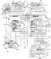
図2は、上記複写機の制御部の構成を示すブロック図である。複写機30の制御部は、メイン画像処理ボード400に搭載されたCPU401により、ユニット毎に配置されたボードに搭載されたCPUを介して各ユニットを構成する機器を統括して制御する。即ち、複写機30の制御部は、複写機30の上面に設けられた操作パネルを管理するオペレーションパネルボード100、複写機30内の各機器を管理するマシンコントロールボード200、光電変換素子44を周辺部品とともに搭載したCCDボード300、画像データに対して基本的な各種の画像処理を施すCPU41を周辺部品とともに搭載したメイン画像処理ボード400、メイン画像処理ボード400における画像処理後の画像データに対して種々の画像処理を選択的に施すサブ画像処理ボード500、並びに、複写機30のプリンタ機能やファクシミリ機能等の拡張機能に対応したプリンタボード601、機能拡張ボード602及びファクシミリボード603等の拡張ボード群600によって構成されている。
【0026】
オペレーションパネルボード700は、メイン画像処理ボード400のCPU401をマスタCPUとするスレーブCPUであるCPU701をメモリ702とともに搭載している。CPU701は、操作パネル75に配置された液晶ディスプレイ(LCD)100に供給する表示データ、及び、タッチパネルを含む操作キー105の操作データを管理し、CPU701に入出力されるデータをメモリ702に一時格納する。なお、操作パネル75の構成については後述する。CPU701はCPU401との間でデータの通信を行い、操作キー105の操作によるオペレータの動作指示の内容を表すデータをCPU401に送信するとともに、CPU401から送信されるデータに基づいて表示装置6に複写機30の動作状態に応じた表示を行う。
【0027】
マシンコントロールボード200は、メイン画像処理ボード400のCPU401をマスタCPUとするスレーブCPUであるCPU201をメモリ202とともに搭載している。CPU201は、後処理装置34、RADF36、スキャナ部31、電子写真プロセス部47及び用紙搬送部50のそれぞれを管理する。CCDボード300は、光電変換素子44、光電変換素子44を駆動するゲートアレイ302、光電変換素子44の出力信号のゲイン調整等を行うアナログ回路303、及び、アナログ回路303の出力信号をディジタルデータに変換するA/D変換回路304を搭載している。これらの光電変換素子44及び各回路302〜304は、メイン画像処理ボード400に搭載されているCPU401によって管理される。
【0028】
メイン画像処理ボード400は、CPU401、多値画像処理部402、メモリ403及びレーザコントロール部404を搭載している。多値画像処理部402は、CCDボード300のA/D変換回路304を介して入力された画像データに対して、画像の階調性を所望の状態で表現するためのシェーディング補正、濃度補正、領域分離、フィルタ処理、MTF補正、解像度変換、変倍処理及びγ補正等の多値の画像データに対する画像処理を実行する。メモリ403は、画像処理後の画像データを画像処理手順管理のための制御データとともに記憶する。レーザコントロール部404は、画像処理後の画像データによってレーザ書込ユニット46の半導体レーザを駆動する。
【0029】
サブ画像処理ボード500は、メイン画像処理ボード400とコネクタ405,505を介して接続されており、メイン画像処理ボード400に搭載されたCPU401によって制御される2値画像処理部501、メモリ502、ハードディスク503及びSCSI504が搭載されている。2値画像処理部501は、多値画像データを2値画像データに変換する変換処理部、画像を回転する回転処理部、及び、2値画像データの倍率変換を行う変倍処理部等の処理部とともに、ファクシミリ画像の送受信を行うファクシミリインタフェースを備えている。また、メモリ502、ハードディスク503及びSCSI504に対するデータの入出力は、ゲートアレイを介して行われる。
【0030】
拡張ボード600には、パーソナルコンピュータ等の外部装置からの画像データの入力を受け付けるプリンタボード601、複写機30が有する編集機能を用いて編集した画像データを外部装置において活用するための機能拡張ボード602、及び、画像データを公衆電話回線網を介して送受信するためのファクシミリボード603等がある。
【0031】
以下に、複写機30におけるコピーモード、プリンタモード及びファクシミリモードのそれぞれにおける画像データの処理について説明する。
【0032】
通常のコピーモード時には、RADF36を介して原稿台35に給送された原稿の画像がスキャナユニット40によって順次読み取られ、8ビットの画像データとしてメイン画像処理ボード400に送られ、多値画像処理部402において所定の画像処理が施された後、レーザコントロール部404を介してレーザ書込ユニット46に供給される。これによって、記録部32において階調性のあるコピー画像が記録用紙上に形成されて出力される。
【0033】
電子RDH機能によるコピーモード時には、RADF36を介して原稿台35に給送された原稿の画像がスキャナユニット40によって順次読み取られ、8ビットの画像データとしてメイン画像処理ボード400に送られ、多値画像処理部402において所定の画像処理が施された後、サブ画像処理ボード500に供給される。サブ画像処理ボード500では、2値画像処理部501において、8ビットの画像データに対して誤差拡散等の処理を含む2値化処理を行い、1ビットの画像データとして原稿1枚毎にハードディスク503に格納される。これらの処理がRADF36にセットされた全ての原稿について実行される。ハードディスク503に格納された複数枚の画像データは、ゲートアレイの制御によりページ順に読み出す処理が設定部数回だけ繰り返して実行され、メイン画像処理ボード400において所定の画像処理の後にレーザコントロール部404を介してレーザ書込ユニット46に供給される。
【0034】
したがって、各原稿の画像を複数部ずつ画像形成する場合にも、各原稿の画像についての読取動作を1回のみ行うだけでよい。また、この電子RDH機能によるコピーモードでは、RADF36にセットされた全ての原稿の画像を一旦ハードディスク503に格納する際に、画像データを2値化するため、ハードディスク503として多量のメモリ容量が必要となることがない。さらに、この2値化処理時に誤差拡散等の処理を実行するため、画質の著しい低下を招くこともない。なお、1部目の画像形成処理時には、ハードディスク503への書込と同時に2値化処理後の画像データをメイン画像処理ボード400に出力するようにしてもよい。
【0035】
プリンタモード時には、パーソナルコンピュータ等の外部装置から入力された画像データはプリンタボード601においてページ単位の画像として展開された後、SCSI504から一旦サブ画像処理ボード500に供給されてハードディスク503に格納される。この時、サブ画像処理ボード500において2値化処理は行わない。ハードディスク503に格納された画像データは、所定のページ順となるように読み出されてメイン画像処理ボード400に出力され、γ補正等の処理の後にレーザコントロール部404を介してレーザ書込ユニット46に供給される。
【0036】
ファクシミリモード時の処理としては、画像データを送信する処理と受信する処理とがある。原稿の画像データを送信する際には、RADF36にセットされた送信原稿が1枚ずつ原稿台35に給送され、スキャナユニット40による読取処理を受ける。スキャナユニット40によって読み取られた送信原稿の画像データは、8ビットの画像データとしてメイン画像処理ボード400の多値画像処理部402において所定の画像処理が施された後にサブ画像処理ボード500に転送され、2値画像処理部501において誤差拡散処理を含む2値化処理、及び、所定の形式による圧縮処理を施された後にメモリ502に格納される。次いで、公衆電話回線網に対して送信先のファクシミリ番号を発呼し、送信可能な状態が確保されると、メモリ502に格納されている画像データを読み出してファクシミリボード603において圧縮形式の変更等の必要な処理を施した後、送信先のファクシミリ装置に送信する。
【0037】
公衆電話回線網を介して送信された画像データを受信する際には、ファクシミリボード603において受信した画像データをファクシミリインタフェースを介して2値画像処理部501に転送し、2値画像処理部501において伸長処理を施してページ画像に再現する。ページ単位の画像として再現された画像データは、メイン画像処理ボード400に転送され、γ補正等の画像処理後にレーザコントロール部404を介してレーザ書込ユニット46に供給される。
【0038】
以上のように、複写機30では、多値画像データを処理するメイン画像処理ボード400と2値画像データを処理するサブ画像処理ボード500とに分割して画像処理部を構成しており、スキャナ部31において読み取られた原稿の画像は、メイン画像処理ボード400において多値画像データとして画像処理してレーザ書込ユニット46に供給することにより、原稿の画像の特徴を損なうことなく記録用紙上に複写画像を形成することができるとともに、大量の原稿の画像を多量部数出力する場合には、サブ画像処理ボード500において2値画像データとして画像処理することにより、処理の高速化を図ることができる。
【0039】
また、画像処理部を分散させることによって複写機の機能の多様化に対応することができる。さらに、メイン画像処理ボード400に搭載されたCPU401によってサブ画像処理ボード500に搭載されている各部を制御するようにしているため、メイン画像処理ボード400及びサブ画像処理ボード500において連続して画像データを処理する際に画像データ及び処理の流れを円滑に行うことができ、画像データの損失を生じることがない。
【0040】
図3は、上記複写機に備えられる操作パネルの平面図である。操作パネル75の中央部には表示装置6が配置されている。操作パネル75における表示装置6の右側には、複写枚数等の数値情報を入力するためのテンキー15、複写動作の実行中に別の複写モードに係る複写動作を割込処理させるための割込キー16、テンキー15等による設定内容を消去するクリアキー17、複写機30に対する全ての設定内容を標準状態に復帰させる全解除キー18、及び、複写動作の開始を指示するためのスタートキー19が配置されている。さらに、操作パネル75における表示装置6の左側には、複写機30の動作モードをファクシミリモード、プリンタモード及びコピーモードのそれぞれに切り換えるためのモード切換キー20〜22が配置されている。
【0041】
なお、上述した操作パネル75における表示装置やキーの配置状態は一例を示すものであり、複写機30が有する機能に応じて配置されるキーや表示装置6における表示内容も変化する。
【0042】
図4は、上記複写機の操作パネルに配置された表示装置の詳細を示す図である。複写機30の表示装置6は、中央に液晶ディスプレイ100を備えている。この液晶ディスプレイ100の左右側面の近傍のパネル面には、表示装置6の表示画面に、画像編集機能の設定のための編集モード設定画面を表示させる特別機能モードキー10、両面複写機能の設定のための両面複写モード設定画面を表示させる両面複写モードキー11、ソータ処理やステープル処理等の後処理機能の設定のための後処理設定画面を表示させるソータ/ステープルキー12、現在設定されているモードの内容を確認するための設定確認キー13、操作方法等のガイダンスを表示させる操作ガイドキー14、ガイダンスの表示内容をスクロールさせるスクロールキー141及び142、並びに、外部装置との通信状況を確認するための通信状況確認キー23が表記されている。
【0043】
表示装置6において、液晶ディスプレイ100の上面、及び、パネル面に表記された特別機能モードキー10等のキーの上面には、タッチパネル101が積層して配置されている。タッチパネル101は、表示装置6に表示されたキー、及び、パネル面に表記されたキーの操作状態を検出する。
【0044】
複写機30は、スタートキー19の操作によるコピー動作開始の指示を待機する標準状態において、表示装置6の液晶ディスプレイ100に図4に示す基本画面を表示する。この基本画面では、中央部に複写機30の外観を示す概略図102が表示される。この概略図102には、複写機30の本体概略図102aやソータ概略図102bとともに給紙部概略図102cが含まれ、本体概略図102a及び給紙部概略図102cには準備されている記録用紙のサイズ等が表示される。また、複写機30の概略図の下方には、コピー濃度を設定するための濃度設定キー7、用紙サイズを設定する用紙サイズ設定キー8、及び、複写倍率を設定する倍率設定キー9が表示される。用紙サイズ設定キー8が、この発明の操作部材に相当する。
【0045】
図5は、上記表示装置において基本画面内のキーが操作された際に表示される設定画面を示す図である。表示装置6の液晶ディスプレイ100に図4に示す基本画面を表示している状態で、両面コピーモードキー11が押圧操作されると、液晶ディスプレイ100の表示画面は図5(A)に示す両面複写モード設定画面に切り換わる。また、表示装置6の液晶ディスプレイ100に図4に示す基本画面を表示している状態で、ソータ/ステープルキー12が押圧操作されると、液晶ディスプレイ100の表示画面は図5(B)に示す後処理設定画面に切り換わる。さらに、表示装置6の液晶ディスプレイ100に図4に示す基本画面を表示している状態で、用紙サイズ設定キー8が押圧操作されると、液晶ディスプレイ100の表示画面は図5(C)に示す用紙サイズ設定画面に切り換わる。
【0046】
図6は、上記複写機の表示装置における両面複写モード設定画面の表示状態を示す図である。図4に示す表示画面において概略図102における本体概略図102aの表示位置、又は、両面コピーキー11の表記位置を押圧操作すると、表示装置6の表示画面は、図6(A)に示す両面複写モード設定画面に切り換わる。この両面複写モード設定画面では、表示装置6に図4の基本画面に表示されていた概略図102の本体概略図102aとともに、両面複写モードにおける処理内容を設定するための設定キーが表示される。
【0047】
即ち、両面複写モード設定画面では、本体概略図102aの左側には片面原稿から片面コピーを作成する標準状態のモードを指示するためのキー106が表示される。また、本体概略図102aの下側には、偶数枚の片面原稿から両面コピーを作成するモードを指示するためのキー107、奇数枚の片面原稿から両面コピーを作成するモードを指示するためのキー108、両面原稿から両面コピーを作成するモードを指示するためのキー109、及び、両面原稿から片面コピーを作成するモードを指示するためのキー110が、それぞれのモードの内容を示すアイコンとともに表示される。さらに、本体概略図102aの右側には、処理すべき片面原稿が偶数枚であるか奇数枚であるかが不明である場合に原稿の枚数を計数する処理を行わせる際に操作するキー111、及び、両面複写モード設定画面における設定操作を終了する際に操作するキー113が表示される。
【0048】
なお、液晶ディスプレイ100における本体概略図102a及びキー106〜113の表示位置は、図6(A)に示す状態に限るものではない。即ち、図6(A)に示す両面複写モード設定画面では本体概略図102aを図4に示した基本画面における表示位置のままで表示しているが、両面複写モード設定画面においてキー106〜113の表示位置を優先的に決定し、本体概略図102aを基本画面における表示位置と異なる位置に表示するようにしてもよい。但し、オペレータの錯誤を防止するためには、両面複写モード設定画面における本体概略図102aの表示位置や表示サイズは基本画面と同一にすることが望ましい。
【0049】
図6(A)に示す両面複写モード設定画面において、キー106〜キー110のいずれかが押圧操作されると、指示された処理内容を示すアイコンが表示画面中の本体概略図102a内に表示される。例えば、図6(A)に示す表示画面において偶数枚の片面原稿から両面コピーを作成するモードを指示するキー107が押圧操作されると、図6(B)に示すように、キー107内に表示されているものと同じアイコン112が本体概略図102a内に表示される。この状態からキー113が押圧操作されると、偶数枚の片面原稿から両面コピーを作成するモードの設定が確定し、液晶ディスプレイ100の表示画面は、図6(C)に示すように、本体概略図102a内にアイコン112を表示したままの状態で基本画面に切り換わる。
【0050】
このように、両面複写モード設定画面の表示中に押圧操作されたキーに表記されているアイコンを以後の表示画面における本体概略図102a内にそのままの状態で表示することにより、オペレータ自身が設定した処理内容の確認を容易に行うことができる。
【0051】
但し、オペレータがキー106を操作して片面原稿についての片面コピーを設定した場合には、両面複写モードが設定されていないことになり、この場合には、キー106内に表記されているアイコンを本体概略図102a内に表示する必要はない。
【0052】
なお、液晶ディスプレイ100が両面複写モード設定画面を表示している間において、操作パネル75において液晶ディスプレイ100に表示されているキー106〜111,113以外のキーによる処理内容の設定入力が可能である場合にも、操作されたキーに表記されているアイコンを本体概略図102a内に表示するようにしてもよい。
【0053】
図7及び図8は、上記複写機の表示装置における後処理設定画面の表示状態を示す図である。図4に示す基本画面において概略図102におけるソータ概略図102bの表示位置、又は、ソータ/ステープルキー12の表記位置を押圧操作すると、液晶ディスプレイ100の表示画面は、図7(A)に示す後処理設定画面に切り換わる。この後処理設定画面では、基本画面に表示されていたソータ概略図102bが表示されるとともに、後処理機能における処理内容を設定するための設定キーが表示される。
【0054】
即ち、液晶ディスプレイ100において、ソータ概略図102bの右側には、コピー済みの用紙を丁合した状態で複数の部数に仕分けるソート機能を指示するためのキー114、コピー済みの用紙に対するステープル処理を施すステープル機能を指示するためのキー115、及び、コピー済みの用紙を丁合した状態で各部毎に異なる位置に排出するオフセット機能を指示するキー116が、それぞれの機能の内容を示すアイコンとともに表示される。また、ソータ概略図102bの右側の上部には、アウトプット機能の表示画面の表示を終了させる際に操作するキー113が表示される。
【0055】
なお、液晶ディスプレイ100におけるソータ概略図102b及びキー113〜116の表示位置は、図7(A)に示す状態に限るものではない。即ち、図7(A)に示す後処理設定画面ではソータ概略図102bを図4に示した基本画面における表示位置のままで表示しているが、後処理設定画面においてキー113〜116の表示位置を優先的に決定し、ソータ概略図102bを基本画面における表示位置と異なる位置に表示するようにしてもよい。但し、オペレータの錯誤を防止するためには、後処理設定画面におけるソータ概略図102bの表示位置や表示サイズは基本画面と同一にすることが望ましい。
【0056】
図7(A)に示す表示画面において、キー114〜キー116のいずれかが押圧操作されると、表示画面中のソータ概略図102b内に指示された処理内容を示すアイコンが表示される。例えば、図7(A)に示す表示画面においてソート機能を指示するキー114が押圧操作されると、図7(B)に示すように、キー114内に表示されているものと同じアイコン117がソータ概略図102b内に表示される。また、図7(A)に示す表示画面において、キー114〜キー116のうち、重複して設定することができる複数の機能に係る複数のキーが押圧操作された場合には、重複して設定された複数の機能を示すアイコンをソータ概略図102b内に表示するようにしてもよい。
【0057】
例えば、ソート機能とステープル機能とが重複して設定された場合には、図7(C)に示すように、キー114及び115のアイコン117及び118を組み合わせたアイコン119をソータ概略図102b内に表示する。図7(B)又は(C)に示す状態からキー113が押圧操作されると、ソート機能又はソート機能とステープル機能の設定が確定し、液晶ディスプレイ100の表示画面は、図8に示すように、ソータ概略図102b内にアイコン118又は119を表示した状態で基本画面に切り換わる。
【0058】
このように、後処理設定画面の表示中に押圧操作されたキーに表記されているアイコンを以後の表示画面におけるソータ概略図102b内にそのままの状態で表示することにより、オペレータ自身が設定した処理内容の確認を容易に行うことができる。
【0059】
但し、オペレータが標準モードにおいて予め設定されている処理内容に係るキーを押圧操作した場合、例えば、複数枚の原稿について複数部のコピーを行う際にコピー用紙をソート処理することが予め設定されている場合には、オペレータがキー114を操作してソート処理を設定してもキー114内に表記されているアイコンをソータ概略図102b内に表示する必要はない。
【0060】
なお、液晶ディスプレイ100が後処理設定画面を表示している間において、操作パネル75において液晶ディスプレイ100に表示されているキー113〜116以外のキーによる処理内容の設定入力が可能である場合にも、操作されたキーに表記されているアイコンをソータ概略図102b内に表示するようにしてもよい。
【0061】
図9は、上記複写機の表示装置における用紙サイズ設定画面の表示状態を示す図である。図4に示す基本画面において概略図102における給紙部概略図102cの表示位置、又は、用紙サイズ設定キー8の表示位置を押圧操作すると、液晶ディスプレイ100の表示画面は、図9(A)に示す用紙サイズ設定画面に移行する。この用紙サイズ設定画面では、図4に示した基本画面における自動選択サイズの表示を消去するとともに、用紙サイズ設定キー8の上方から右側にかけて、複写機30の給紙部における実際の位置関係に対応した位置に給紙位置120a〜120hが表示される。このとき、給紙位置120a〜120hは、基本画面における概略図102の上に重ねた状態で表示される。
【0062】
図10は、上記複写機の制御部の用紙設定モード時における処理手順を示すフローチャートである。液晶ディスプレイ100に図4に示す基本画面を表示している間において、概略図102における給紙部概略図102cの表示位置、又は、用紙サイズ設定キー8の表示位置が押圧操作されると、オペレーションパネルボート700のCPU701は、用紙サイズ設定モードの処理を開始し、液晶ディスプレイ100に図9(A)に示す用紙サイズ設定画面を表示し(s1)、用紙サイズ設定キー8の操作を待機する(s2)。
【0063】
CPU701は、用紙サイズ設定キー8が操作されると、カウンタCの計数値をインクリメントする(s3)。このカウンタCは、メモリ702の所定のメモリエリアに割り当てられている。カウンタCの計数値は、用紙サイズ設定画面における給紙位置120a〜120hのいずれかを特定する値であり、給紙位置120a〜120hのそれぞれに対応した“1”〜“8”の値をとる。
【0064】
CPU701は、インクリメント後のカウンタCの計数値が最大値Cm(この例ではCm=8)を越えるか否かを判別し(s4)、カウンタCの計数値が最大値Cmを越える場合にはカウンタCの計数値を“1”にする(s5)。この後、CPU701は、用紙サイズ設定画面における給紙位置120a〜120hのうちでカウンタCの計数値に対応する給紙位置を反転表示する(s6)。
【0065】
CPU701は、用紙サイズ設定キー8の操作を待機している間において、複写機30の各給紙位置に配置されたセンサが新たな用紙の装填を検出した場合には、新たな用紙が装填された給紙位置に対応する計数値Csを判別し(s7→s8)、カウンタCに(Cs−1)を設定する(s9)。CPU701は、用紙サイズ設定キー8の操作、及び、新たな用紙の装填がなされることなく所定時間を経過した時に、カウンタCの計数値に対応する給紙位置を用紙を給紙すべき位置として確定し、図9(B)に示すように、確定した給紙位置を反転表示した状態で基本画面を液晶ディスプレイ100に表示して用紙サイズ設定モードの処理を終了する(s2→s7→s10,s11)。
【0066】
以上の処理により、オペレータが用紙サイズ設定モードを選択して複写機30の給紙部のいずれかの給紙位置に新たな用紙を装填した場合には、オペレータがその後に最初に用紙サイズ設定キー8を操作した際に、新たな用紙が装填された給紙位置が選択される。通常、オペレータが新たな用紙を装填した場合には、新たに装填された用紙を用いてコピー処理が実行される可能性が高い。一方で、複写作業を実行しようとしているオペレータとは別のオペレータが次の複写作業において給紙すべき用紙を給紙部に予め装填する場合や、所望のサイズと異なるサイズの用紙が用紙切れを起こしていることに気づいたオペレータがそのサイズの用紙を補充する場合も考えられ、必ずしも新たに装填された用紙を用いてコピー処理が実行されるとは限らない。そこで、オペレータが用紙サイズ設定キー8を操作することによる確認作業を待って新たに装填された用紙を選択するようにし、用紙サイズの選択作業をオペレータの意思を反映した状態で効率よく、かつ、正確に行うことができる。
【0067】
図11は、この発明の別の実施形態に係る複写機の制御部の用紙設定モード時における処理手順を示すフローチャートである。液晶ディスプレイ100に図4に示す基本画面を表示している間において給紙部概略図102cの表示位置、又は、用紙サイズ設定キー8の表示位置が押圧操作されると、オペレーションパネルボート700のCPU701は、用紙サイズ設定モードの処理を開始し、液晶ディスプレイ100に図9(A)に示す用紙サイズ設定画面を表示し(s21)、用紙サイズ設定キー8の操作を待機する(s22)。
【0068】
CPU701は、用紙サイズ設定キー8が操作されると、タイマTがタイムアップしたか否かの判別を行う(s23)。このタイマTはメモリ702の所定のメモリエリアに割り当てられており、予め設定された一定時間を計時する。CPU701は、タイマTがタイムアップしていない場合にはカウンタCに(Cs−1)を設定した後(s24)、タイマTがタイムアップしている場合にはそのまま、カウンタCの計数値をインクリメントする(s25)。このカウンタCは、図10に示した処理におけるカウンタCと同様である。また、計数値Csは、後述する処理によってメモリ702の所定のメモリエリアに記憶されている。
【0069】
CPU701は、インクリメント後のカウンタCの計数値が最大値Cm(この例ではCm=8)を越えるか否かを判別し(s26)、カウンタCの計数値が最大値Cmを越える場合にはカウンタCの計数値を“1”にする(s27)。この後、CPU701は、用紙サイズ設定画面における給紙位置120a〜120hのうちでカウンタCの計数値に対応する給紙位置を反転表示する(s28)。
【0070】
CPU701は、用紙サイズ設定キー8の操作を待機している間において、複写機30の各給紙位置に配置されたセンサが新たな用紙の装填を検出した場合には、タイマTを起動した後(s29,s30)、新たな用紙が装填された給紙位置に対応する計数値Csを判別し(s31)、この判別結果をメモリ702の所定のメモリエリアに記憶する(s32)。CPU701は、用紙サイズ設定キー8の操作、及び、新たな用紙の装填がなされることなく所定時間を経過した時に、カウンタCの計数値に対応する給紙位置を用紙を給紙すべき位置として確定し、図9(B)に示すように、確定した給紙位置を反転表示した状態で基本画面を液晶ディスプレイ100に表示して用紙サイズ設定モードの処理を終了する(s33,s34)。
【0071】
以上の処理により、オペレータが用紙サイズ設定モードを選択して複写機30の給紙部のいずれかの給紙位置に新たな用紙を装填した場合には、新たな用紙が装填された後、所定時間を経過するまでの間にオペレータが用紙サイズ設定キー8を操作した際に新たな用紙が装填された給紙位置が最初に選択される。これによって、用紙サイズ設定モードが設定されている間において、新たに用紙が装填された時から最初に用紙サイズ設定キー8が操作されるまでに所定時間を経過するか否かに応じて、用紙サイズ設定キー8の操作による給紙位置の選択順序を変更するようにし、用紙サイズの選択をさらに効率よく、かつ、正確に行うことができる。
【0072】
図12は、この発明のさらに別の実施形態に係る複写機の制御部の処理手順の一部を示すフローチャートである。この実施形態に係る複写機では、設定されているモードに拘らず、センサが給紙部における新たな用紙の装填が検出された際に、図12(A)に示すセンサ割込処理を実行する。このセンサ割込処理では、CPU701は、メモリ702の所定のメモリエリアに割り当てられているタイマTを起動した後に(s41)、用紙が新たに装填された給紙位置に対応するカウンタCの計数値Csを判別し(s42)、この判別結果をメモリ702の所定のメモリエリアに記憶する(s43)。なお、タイマT及びカウンタCは、図11に示した処理において使用したタイマT及びカウンタCと同様に機能する。
【0073】
一方、CPU701は、オペレータが液晶ディスプレイ100に図4に示す基本画面を表示している間において給紙部概略図102cの表示位置、又は、用紙サイズ設定キー8の表示位置が押圧操作されると、オペレーションパネルボート700のCPU701は、用紙サイズ設定モードの処理を開始し、液晶ディスプレイ100に図9(A)に示す用紙サイズ設定画面を表示し(s51)、用紙サイズ設定キー8の操作を待機する(s52)。
【0074】
CPU701は、用紙サイズ設定キー8が操作されると、タイマTがタイムアップしたか否かの判別を行う(s53)。このタイマTはメモリ702の所定のメモリエリアに割り当てられており、予め設定された一定時間を計時する。CPU701は、タイマTがタイムアップしていない場合にはカウンタCに(Cs−1)を設定した後(s54)、タイマTがタイムアップしている場合にはそのまま、カウンタCの計数値をインクリメントする(s55)。
【0075】
CPU701は、インクリメント後のカウンタCの計数値が最大値Cm(この例ではCm=8)を越えるか否かを判別し(s56)、カウンタCの計数値が最大値Cmを越える場合にはカウンタCの計数値を“1”にする(s57)。この後、CPU701は、用紙サイズ設定画面における給紙位置120a〜120hのうちでカウンタCの計数値に対応する給紙位置を反転表示する(s58)。
【0076】
以上の処理により、オペレータが複写機30の給紙部のいずれかの給紙位置に新たな用紙を装填した場合には、新たな用紙が装填された後、用紙サイズ設定モードにおいて、所定時間を経過するまでの間にオペレータが用紙サイズ設定キー8を操作した際に新たな用紙が装填された給紙位置が最初に選択される。これによって、新たに用紙が装填された時から用紙サイズ設定モードが設定され、さらに、最初に用紙サイズ設定キー8が操作されるまでに所定時間を経過するか否かに応じて、用紙サイズ設定キー8の操作による給紙位置の選択順序を変更するようにし、新たな用紙が装填された際に設定されているモードに拘らず、常に、用紙サイズの選択を効率よく、かつ、正確に行うことができる。
【0077】
なお、上述したいずれの実施形態に係る複写機においても、用紙サイズ設定キー8が操作される毎に複数の給紙位置のそれぞれを1方向に順次切り換えて選択するようにしたが、用紙サイズ設定キー8をカウントアップキー及びカウントダウンキーによって構成し、カウントアップキー又はカウントダウンキーが操作される毎に、複数の給紙位置のそれぞれを互いに異なる2方向に順次切り換えて選択するようにしてもよい。この場合において、新たな用紙が給紙部に装填された後に最初にカウントアップキー又はカウントダウンキーが操作された時に、新たに装填された用紙を給紙すべき用紙として選択する。
【0078】
以上、この発明の実施形態を複写機を例にあげて説明したが、給紙部にセットされている複数種の用紙のいずれかを選択的に処理部に給紙して用紙に対する処理を実行する他の用紙処理装置においても、この発明を同様に実施することができる。また、給紙部の複数の給紙位置に収納する複数種の用紙は、互いにサイズが異なる用紙のみならず、素材や厚さが互いに異なる用紙であってもよい。
【0079】
【発明の効果】
請求項1に記載した発明によれば、新たに収納された用紙から所定の順序で給紙すべき用紙を選択することにより、給紙すべき用紙を給紙部に収納した後の用紙の選択作業では処理部に給紙すべき用紙を素早く選択することができるとともに、給紙すべき用紙と異なる用紙を給紙部に収納した後の用紙の選択作業では所定の順序にしたがって処理部に給紙すべき用紙を選択することができ、オペレータの意思を反映した状態で用紙サイズの選択を効率よく、かつ、正確に行うことができる。これによって、用紙の選択作業を簡略化及び短時間化して装置の稼働効率を向上することができ、オペレータの意思に反した用紙が給紙されることによる用紙の無駄を確実に防止することができる。
【0080】
請求項2に記載した発明によれば、新たな用紙の収納タイミングから所定時間を経過するまでの間において、新たに収納された用紙から所定の順序で給紙すべき用紙を選択することにより、給紙すべき用紙を給紙部に収納してから所定時間を経過するまでの間における用紙の選択作業では処理部に給紙すべき用紙を素早く選択することができるとともに、用紙を給紙部に収納してから所定時間を経過した後、又は、給紙すべき用紙と異なる用紙を給紙部に収納した後の用紙の選択作業では所定の順序にしたがって処理部に給紙すべき用紙を選択することができ、オペレータの意思を反映した状態で用紙サイズの選択をさらに効率よく、かつ、正確に行うことができる。これによって、用紙の選択作業を簡略化及び短時間化して装置の稼働効率をより向上することができ、オペレータの意思に反した用紙が給紙されることによる用紙の無駄をより確実に防止することができる。
【0082】
請求項3に記載した発明によれば、新たに収納された用紙から所定の順序で画像形成部に給紙すべき用紙を選択することにより、給紙すべき用紙を給紙部に収納した後の用紙の選択作業では、画像形成部に給紙すべき用紙を素早く選択することができるとともに、給紙すべき用紙と異なる用紙を給紙部に収納した後の用紙の選択作業では、所定の順序にしたがって画像形成部に給紙すべき用紙を選択することができ、オペレータの意思を反映した状態で用紙サイズの選択を効率よく、かつ、正確に行うことができる。これによって、用紙の選択作業を簡略化及び短時間化して画像形成装置の稼働効率を向上することができ、オペレータの意思に反した用紙が給紙されることによる用紙の無駄を確実に防止することができる。
【図面の簡単な説明】
【図1】この発明の実施形態に係る用紙処理装置であるディジタル複写機の構成を示す図である。
【図2】上記複写機の制御部の構成を示すブロック図である。
【図3】上記複写機に備えられる操作パネルの平面図である。
【図4】上記複写機の操作パネルに配置された表示装置の詳細を示す図である。
【図5】上記表示装置において基本画面内のキーが操作された際に表示される設定画面を示す図である。
【図6】上記複写機の表示装置における両面複写モード設定画面の表示状態を示す図である。
【図7】上記複写機の表示装置における後処理設定画面の表示状態を示す図である。
【図8】上記複写機の表示装置における後処理設定画面の表示状態を示す図である。
【図9】上記複写機の表示装置における用紙サイズ設定画面の表示状態を示す図である。
【図10】上記複写機の制御部の用紙設定モード時における処理手順を示すフローチャートである。
【図11】この発明の別の実施形態に係る複写機の制御部の用紙設定モード時における処理手順を示すフローチャートである。
【図12】この発明のさらに別の実施形態に係る複写機の制御部の用紙設定モード時における処理手順を示すフローチャートである。
【符号の説明】
8−用紙サイズ設定キー
30−複写機
51,52−給紙カセット
54−手差しトレイ[0001]
[Industrial application fields]
The present invention relates to a sheet processing apparatus that selectively supplies one of a plurality of types of sheets stored in a sheet feeding unit to a processing unit and executes a predetermined process on the sheet.
[0002]
[Prior art]
In a paper processing device such as an image forming apparatus that feeds paper stored in a paper feeding unit to a processing unit and executes predetermined processing on the paper, paper of a size corresponding to the processing for the paper is fed to the processing unit. There is a need to. For example, in a copying machine that copies a document image onto a sheet, it is necessary to feed a sheet having a size corresponding to the image size of the document and the copy magnification to the processing unit. Further, sheets of different materials and thicknesses are fed to the processing unit according to the purpose of use of the sheets after the process is completed. For example, when copying a cover image in a copying machine, a sheet having a material and a thickness different from those of a body image may be fed to the processing unit.
[0003]
As described above, in a paper processing apparatus in which a plurality of types of paper may be fed from the paper feeding unit to the processing unit, the paper feeding unit is previously set to facilitate replacement of the paper to be fed. A plurality of types of sheets are stored, and a sheet to be fed to the processing unit among a plurality of types of sheets stored in the sheet feeding unit can be selected by operating an operation member such as a sheet selection key. There is something that was made. In this sheet processing apparatus, a sheet to be fed to the processing unit among a plurality of types of sheets stored in the sheet feeding unit is switched and set in a predetermined order each time the operation member is operated.
[0004]
However, in a paper processing apparatus that can store many types of paper in the paper supply unit, the operator repeatedly operates the operation member many times before setting the desired type of paper as the paper to be supplied to the processing unit. There is a problem that the operation of selecting a sheet to be fed to the processing unit becomes complicated and takes a long time, resulting in a decrease in operating efficiency of the sheet processing apparatus.
[0005]
Therefore, Japanese Patent Publication No. 62-40257 discloses that when a new sheet is loaded in the sheet feeding unit, the newly loaded sheet is fed to the processing unit regardless of the operation of the operation member. The configuration is disclosed. With this configuration, when a sheet of paper that the operator desires to execute is loaded in the sheet feeding unit, the newly loaded sheet is automatically selected and fed to the processing unit without operating the operation member. Thus, it is possible to simplify the operation of selecting paper to be fed to the processing unit, and waste of paper due to a paper feeding error when the operator forgets to operate the operation member after loading the paper into the paper feeding unit. Can be prevented.
[0006]
[Problems to be solved by the invention]
However, in the configuration disclosed in Japanese Examined Patent Publication No. 62-40257, when a new sheet is loaded in the sheet feeding unit, the operator can select the sheet to be fed to the processing unit by operating the operation member. The operator's intention cannot be reflected in the selection of the sheet to be fed to the processing unit. For this reason, for example, an operator who notices that any of a plurality of types of paper to be stored in the paper feed unit has run out of paper performs a loading operation for paper that does not desire paper feed to the processing unit. If a new paper is not supplied to the processing unit, such as when an operator other than the operator who selects the paper is loaded, or when a paper is loaded into the paper supply unit, etc. If the sheet is loaded, a sheet different from the sheet desired by the operator is fed to the processing unit, and the sheet feeding operation cannot be performed accurately.
[0007]
An object of the present invention is to set a newly stored sheet as a sheet to be fed to the processing unit after waiting for an operation of the operation member by the operator when a new sheet is stored in the sheet feeding unit. An object of the present invention is to provide a sheet processing apparatus capable of efficiently and accurately selecting a sheet to be fed to a processing unit.
[0008]
[Means for Solving the Problems]
The invention described in
The counter includes a counter that counts the number of operations of the operation member with the number of the paper feed positions as a maximum value, and a value for specifying the paper feed position in each of the paper feed positions is set in advance. Select the paper at the paper feed position that has a value corresponding to the count value of
In the paper size setting modeAny of multiple paper feed positionsWhen new paper is stored,The value corresponding to the paper feed position where the paper is stored is set to the value when the operation member is operated next time.Paper to be fed to the processing unitPaper feed positionAsThe value to be determined is set in the counter, and the feeding position where the value corresponding to the count value of the counter is set when the predetermined time has passed without the operation member being operated next should be fed. A means to confirm the paper feed position where the paper was stored was providedIt is characterized by.
[0009]
Claim1In the described invention, when a new paper is stored in the paper supply unit prior to the selection operation of the paper to be supplied, the paper to be supplied in a predetermined order is selected from the newly stored paper. Therefore, in the paper selection operation after the paper to be fed is stored in the paper feeding unit, the paper to be fed to the processing unit is quickly selected, and a paper different from the paper to be fed is fed to the paper feeding unit. In the paper selection operation after storing, the paper to be fed to the processing unit is selected according to a predetermined order.
[0010]
Claim2The invention described in theIn contrast, a timing unit that measures the elapsed time from the storage timing for the latest storage timing is provided, and each time the operation member is operated until the timing unit counts a predetermined time, A paper feed position in which a value corresponding to the count value of the counter is set when a predetermined time elapses is selected by switching in order from the latest paper, as a paper feed position containing the paper to be fed. ConfirmIt is characterized by doing.
[0011]
Claim2In the invention described above, when a new sheet is stored in the sheet feeding unit prior to the selection operation of the sheet to be fed, the sheet is newly stored until a predetermined time elapses after the new sheet is stored. The paper to be fed in a predetermined order is selected from the printed paper. Therefore, in the paper selection operation after the paper to be fed is stored in the paper feeding unit until a predetermined time elapses, the paper to be fed to the processing unit is quickly selected and the paper is fed. When selecting a sheet after a predetermined time has elapsed since it was stored in the storage unit or after storing a sheet different from the sheet to be supplied in the sheet supply unit, the sheet should be supplied to the processing unit in a predetermined order. Paper is selected.
[0014]
Claim3In the invention described in the above item, the processing unit is an image forming unit that forms an image on a sheet fed from a sheet feeding unit.
[0015]
Claim3In the invention described in the above, when a new sheet is stored in the sheet feeding unit prior to the operation of selecting a sheet to be fed to the image forming unit, the sheet should be fed in a predetermined order from the newly stored sheet. Paper is selected. Therefore, in the paper selection operation after the paper to be fed is stored in the paper feeding unit, the paper to be fed to the image forming unit is quickly selected and a paper different from the paper to be fed is fed to the paper feeding unit. In the paper selection operation after storing the paper, the paper to be fed to the image forming unit is selected according to a predetermined order.
[0016]
DETAILED DESCRIPTION OF THE INVENTION
FIG. 1 is a diagram showing the configuration of a digital copying machine which is a paper processing apparatus according to an embodiment of the present invention. A
[0017]
The digital copying
[0018]
The
[0019]
The
[0020]
The
[0021]
Also, the paper transport unit 50 transfers the paper that has passed through the fixing roller 49 in the double-sided copying mode in which images are formed on both sides of the paper or in the multiple copying mode in which images of a plurality of documents are formed on one side of the paper. Or a sub-conveying path that leads to the
[0022]
The
[0023]
The
[0024]
The paper transport unit 50 guides the paper between the
[0025]
FIG. 2 is a block diagram showing the configuration of the control unit of the copying machine. The control unit of the copying
[0026]
The
[0027]
The
[0028]
The main
[0029]
The sub
[0030]
The
[0031]
Hereinafter, processing of image data in each of the copy mode, printer mode, and facsimile mode in the copying
[0032]
In the normal copy mode, the image of the document fed to the document table 35 via the
[0033]
In the copy mode using the electronic RDH function, the image of the document fed to the document table 35 via the
[0034]
Therefore, even when a plurality of copies of each original image are formed, it is only necessary to read the original image once. In the copy mode using the electronic RDH function, when the images of all the originals set in the
[0035]
In the printer mode, image data input from an external device such as a personal computer is developed as a page unit image on the
[0036]
Processing in the facsimile mode includes processing for transmitting image data and processing for receiving image data. When transmitting image data of a document, transmission documents set in the
[0037]
When receiving image data transmitted via the public telephone network, the image data received by the
[0038]
As described above, the copying
[0039]
In addition, by dispersing the image processing unit, it is possible to cope with diversification of functions of the copying machine. Further, since the CPU 401 mounted on the main
[0040]
FIG. 3 is a plan view of an operation panel provided in the copying machine. A
[0041]
Note that the display device and key arrangement state on the
[0042]
FIG. 4 is a diagram showing details of the display device arranged on the operation panel of the copying machine. The
[0043]
In the
[0044]
The copying
[0045]
FIG. 5 is a diagram showing a setting screen displayed when a key in the basic screen is operated on the display device. When the double-sided copy mode key 11 is pressed while the basic screen shown in FIG. 4 is displayed on the
[0046]
FIG. 6 is a diagram showing a display state of the double-sided copying mode setting screen in the display device of the copying machine. When the display position of the main body schematic diagram 102a in the schematic diagram 102 or the notation position of the double-sided copy key 11 in the schematic diagram 102 is pressed on the display screen illustrated in FIG. 4, the display screen of the
[0047]
That is, on the duplex copy mode setting screen, a key 106 for instructing a standard mode for creating a simplex copy from a simplex original is displayed on the left side of the main body schematic diagram 102a. Also, on the lower side of the main body schematic diagram 102a, a key 107 for instructing a mode for creating a double-sided copy from an even number of single-sided originals, and a key for instructing a mode for creating a double-sided copy from an odd number of single-
[0048]
Note that the display positions of the main body schematic diagram 102a and the
[0049]
When any of the
[0050]
In this way, the icon set on the key pressed during display of the duplex copy mode setting screen is displayed as it is in the main body schematic diagram 102a on the subsequent display screen, so that the operator himself sets it. The processing content can be easily confirmed.
[0051]
However, when the operator operates the key 106 to set single-sided copying for a single-sided document, the double-sided copying mode is not set. In this case, the icon written in the key 106 is displayed. It is not necessary to display in the main body schematic diagram 102a.
[0052]
Note that while the
[0053]
7 and 8 are views showing the display state of the post-processing setting screen in the display device of the copying machine. When the display position of the sorter schematic diagram 102b in the schematic diagram 102 in the basic screen shown in FIG. 4 or the notation position of the sorter /
[0054]
That is, on the
[0055]
Note that the display positions of the sorter schematic diagram 102b and the
[0056]
When any one of the
[0057]
For example, when the sorting function and the stapling function are set to overlap, as shown in FIG. 7C, an
[0058]
In this way, the icon set on the key pressed during display of the post-processing setting screen is displayed as it is in the sorter schematic diagram 102b on the subsequent display screen, so that the processing set by the operator himself is performed. The contents can be easily confirmed.
[0059]
However, when the operator presses a key related to the processing content set in advance in the standard mode, for example, when copying a plurality of copies of a plurality of documents, it is preset that the copy paper is sorted. If the operator operates the key 114 to set the sort process, the icon written in the key 114 does not need to be displayed in the sorter schematic diagram 102b.
[0060]
It should be noted that while the
[0061]
FIG. 9 is a diagram showing a display state of a paper size setting screen in the display device of the copying machine. When the display position of the paper supply unit schematic diagram 102c in the schematic diagram 102 in FIG. 4 or the display position of the paper
[0062]
FIG. 10 is a flowchart showing a processing procedure in the paper setting mode of the control unit of the copying machine. While the basic screen shown in FIG. 4 is displayed on the
[0063]
When the paper
[0064]
The
[0065]
When the
[0066]
As a result of the above processing, when the operator selects the paper size setting mode and loads a new paper in one of the paper feed positions of the copying
[0067]
FIG. 11 is a flowchart showing a processing procedure in the paper setting mode of the control unit of the copying machine according to another embodiment of the present invention. When the display position of the sheet feeder schematic diagram 102c or the display position of the paper
[0068]
When the paper
[0069]
The
[0070]
When the
[0071]
As a result of the above processing, when the operator selects the paper size setting mode and loads a new sheet at any of the sheet feeding positions of the copying
[0072]
FIG. 12 is a flowchart showing a part of the processing procedure of the control unit of the copying machine according to still another embodiment of the present invention. In the copying machine according to this embodiment, the sensor interrupt process shown in FIG. 12A is executed when the sensor detects that a new sheet is loaded in the sheet feeding unit, regardless of the set mode. . In this sensor interrupt process, the
[0073]
On the other hand, the
[0074]
When the paper
[0075]
The
[0076]
As a result of the above processing, when the operator loads a new sheet at any one of the sheet feeding positions of the copying
[0077]
In each of the copiers according to any of the above-described embodiments, each time the paper
[0078]
As described above, the embodiment of the present invention has been described by taking a copying machine as an example. However, one of a plurality of types of paper set in the paper feeding unit is selectively fed to the processing unit, and processing on the paper is executed. The present invention can be similarly implemented in other sheet processing apparatuses. Further, the plurality of types of sheets stored in the plurality of sheet feeding positions of the sheet feeding unit may be not only sheets having different sizes but also sheets having different materials and thicknesses.
[0079]
【The invention's effect】
Claim1According to the described invention, by selecting a sheet to be fed in a predetermined order from newly stored sheets, a processing unit is selected in the sheet selection operation after the sheet to be fed is stored in the sheet feeding unit. The paper to be fed to the processing unit can be quickly selected, and the paper to be fed to the processing unit according to a predetermined order in the paper selection operation after the paper different from the paper to be fed is stored in the paper feeding unit The paper size can be selected efficiently and accurately in a state reflecting the operator's intention. This simplifies and shortens the paper selection operation and improves the operating efficiency of the apparatus, and can reliably prevent paper waste due to paper being fed against the operator's will. it can.
[0080]
Claim2According to the invention described in the above, the paper is fed by selecting the paper to be fed in a predetermined order from the newly stored paper until a predetermined time elapses after the new paper storage timing. In the paper selection operation from when the paper to be fed is stored in the paper feeding unit until a predetermined time elapses, the paper to be fed to the processing unit can be quickly selected, and the paper is stored in the paper feeding unit. In a paper selection operation after a predetermined time has elapsed or after a paper different from the paper to be fed is stored in the paper feeding unit, the paper to be fed to the processing unit is selected according to a predetermined order. The paper size can be selected more efficiently and accurately while reflecting the operator's intention. As a result, it is possible to simplify and shorten the paper selection operation to improve the operation efficiency of the apparatus, and more reliably prevent paper waste due to paper feeding contrary to the operator's intention. be able to.
[0082]
Claim3According to the invention described in the above, by selecting the paper to be fed to the image forming unit in a predetermined order from the newly stored paper, the paper after the paper to be fed is stored in the paper feeding unit is selected. In the selection operation, it is possible to quickly select a sheet to be fed to the image forming unit, and in the sheet selection operation after a sheet different from the sheet to be fed is stored in the sheet feeding unit, according to a predetermined order. The paper to be fed to the image forming unit can be selected, and the paper size can be selected efficiently and accurately while reflecting the operator's intention. As a result, it is possible to simplify and shorten the paper selection operation to improve the operation efficiency of the image forming apparatus, and to reliably prevent paper waste due to paper being fed against the operator's intention. be able to.
[Brief description of the drawings]
FIG. 1 is a diagram showing a configuration of a digital copying machine which is a paper processing apparatus according to an embodiment of the present invention.
FIG. 2 is a block diagram illustrating a configuration of a control unit of the copying machine.
FIG. 3 is a plan view of an operation panel provided in the copying machine.
FIG. 4 is a diagram showing details of a display device arranged on the operation panel of the copying machine.
FIG. 5 is a diagram showing a setting screen displayed when a key in the basic screen is operated in the display device.
FIG. 6 is a diagram showing a display state of a double-sided copying mode setting screen in the display device of the copying machine.
FIG. 7 is a diagram showing a display state of a post-processing setting screen in the display device of the copying machine.
FIG. 8 is a diagram showing a display state of a post-processing setting screen on the display device of the copying machine.
FIG. 9 is a diagram illustrating a display state of a paper size setting screen in the display device of the copying machine.
FIG. 10 is a flowchart showing a processing procedure in the paper setting mode of the control unit of the copying machine.
FIG. 11 is a flowchart showing a processing procedure in a paper setting mode of a control unit of a copying machine according to another embodiment of the present invention.
FIG. 12 is a flowchart showing a processing procedure in a paper setting mode of a control unit of a copying machine according to still another embodiment of the present invention.
[Explanation of symbols]
8-Paper size setting key
30-copier
51,52-paper cassette
54-Bypass tray
Claims (3)
Translated fromJapanese前記操作部材の操作回数を前記給紙位置の数を最大値として計数するカウンタを備えるとともに、前記給紙位置のそれぞれに、給紙位置として特定するための値を予め設定しておき、前記カウンタの計数値に対応する値が設定されている給紙位置の用紙を給紙すべき用紙として選択し、
用紙サイズ設定モード時に給紙部における複数の給紙位置の何れかに新たに用紙が収納された場合に、該新たに用紙が収納された給紙位置に対応する値を、次に前記操作部材が操作された際に処理部に給紙すべき用紙を収納した給紙位置として確定される値として前記カウンタに設定し、次に前記操作部材が操作されることなく所定時間が経過した時に前記カウンタの計数値に対応する値が設定されている給紙位置を給紙すべき用紙を収納した給紙位置として確定する手段を設けたことを特徴とする用紙処理装置。An operation member for accepting a setting operation of the paper to be fed paper processing section in the paper size setting mode,the paper stored ineach of the plurality of paper feed position in the feed unit each time the operating member is operatedIn the sheet processing apparatus that selects a sheet to be fed to the processing unit ina predetermined orderbased on the values specifying the plurality of sheet feeding positions, and executes a predetermined process on the sheet fed to the processing unit ,
The counter includes a counter that counts the number of operations of the operation member with the number of the paper feed positions as a maximum value, and a value for specifying the paper feed position in each of the paper feed positions is set in advance. Select the paper at the paper feed position that has a value corresponding to the count value of
When the new sheetto one of a plurality of paper feeding position definitive the feed unit is stored in the paper size setting mode,a value corresponding to the feeding position in which the newsheet is accommodated, then the operation When the member is operated, thecounter is set as a value determined as apaper feed position in which the paper to be fedto the processing unitis stored, and then when a predetermined time elapses without the operation member being operated. A paper processing apparatus, comprising:means for determining a paper feed position in which a value corresponding to a count value of the counter is set as a paper feed position storing a paper to be fed .
Priority Applications (2)
| Application Number | Priority Date | Filing Date | Title |
|---|---|---|---|
| JP22415898AJP4024394B2 (en) | 1998-08-07 | 1998-08-07 | Paper processing device |
| US09/361,844US6244585B1 (en) | 1998-08-07 | 1999-07-27 | Sheet processing apparatus with switching among plural types of paper |
Applications Claiming Priority (1)
| Application Number | Priority Date | Filing Date | Title |
|---|---|---|---|
| JP22415898AJP4024394B2 (en) | 1998-08-07 | 1998-08-07 | Paper processing device |
Publications (2)
| Publication Number | Publication Date |
|---|---|
| JP2000053263A JP2000053263A (en) | 2000-02-22 |
| JP4024394B2true JP4024394B2 (en) | 2007-12-19 |
Family
ID=16809448
Family Applications (1)
| Application Number | Title | Priority Date | Filing Date |
|---|---|---|---|
| JP22415898AExpired - Fee RelatedJP4024394B2 (en) | 1998-08-07 | 1998-08-07 | Paper processing device |
Country Status (2)
| Country | Link |
|---|---|
| US (1) | US6244585B1 (en) |
| JP (1) | JP4024394B2 (en) |
Families Citing this family (6)
| Publication number | Priority date | Publication date | Assignee | Title |
|---|---|---|---|---|
| JP4035339B2 (en)* | 2002-02-06 | 2008-01-23 | キヤノン株式会社 | Document reader |
| US7066871B1 (en)* | 2003-06-05 | 2006-06-27 | Bescorp, Inc. | Folder with set feeder and telescoping stacker |
| JP2005145624A (en)* | 2003-11-13 | 2005-06-09 | Canon Inc | Image forming apparatus |
| USD529074S1 (en)* | 2004-03-15 | 2006-09-26 | Murata Kikai Kabushiki Kaisha | Operation panel |
| JP4706499B2 (en)* | 2006-02-20 | 2011-06-22 | 富士ゼロックス株式会社 | Image forming apparatus and method |
| US20090194934A1 (en)* | 2008-02-06 | 2009-08-06 | Kabushiki Kaisha Toshiba | Paper feeding device for image forming apparatus |
Family Cites Families (4)
| Publication number | Priority date | Publication date | Assignee | Title |
|---|---|---|---|---|
| JPS5675665A (en) | 1979-11-26 | 1981-06-22 | Konishiroku Photo Ind Co Ltd | Paper feeding system of recording apparatus |
| JPH0697965B2 (en) | 1985-08-13 | 1994-12-07 | 旭電化工業株式会社 | Method for producing oil-in-water type emulsified fat with custard flavor |
| US5271614A (en)* | 1989-05-09 | 1993-12-21 | Sharp Kabushiki Kaisha | Sheet supplying device |
| JP3177052B2 (en)* | 1993-03-22 | 2001-06-18 | 株式会社東芝 | Image forming device |
- 1998
- 1998-08-07JPJP22415898Apatent/JP4024394B2/ennot_activeExpired - Fee Related
- 1999
- 1999-07-27USUS09/361,844patent/US6244585B1/ennot_activeExpired - Lifetime
Also Published As
| Publication number | Publication date |
|---|---|
| US6244585B1 (en) | 2001-06-12 |
| JP2000053263A (en) | 2000-02-22 |
Similar Documents
| Publication | Publication Date | Title |
|---|---|---|
| JP3880282B2 (en) | Input display device | |
| JP3558853B2 (en) | Guidance information display device | |
| JP3540963B2 (en) | Information display device | |
| JP3469079B2 (en) | Image forming device | |
| US7006249B2 (en) | Image forming system | |
| WO1992000644A1 (en) | Device for forming image | |
| JPH11288344A (en) | Information processing device | |
| JP2000089889A (en) | Input display device | |
| JP3527633B2 (en) | Display input device | |
| JP4159522B2 (en) | Information processing device | |
| JP3266809B2 (en) | Image forming device | |
| JP3546003B2 (en) | Input display device and input display method | |
| JP4024394B2 (en) | Paper processing device | |
| JP2009232354A (en) | Image reading apparatus and copier | |
| JP3545179B2 (en) | Image forming system | |
| US6504627B1 (en) | Image processing device | |
| EP1001602B1 (en) | Image output processing apparatus | |
| JP3649920B2 (en) | Image forming apparatus | |
| JP2005035101A (en) | Image forming apparatus | |
| JP3871417B2 (en) | Image processing device | |
| JP4602316B2 (en) | Image forming apparatus | |
| JP3679342B2 (en) | Facsimile device | |
| JP2001022224A (en) | Image forming device | |
| JP3645188B2 (en) | Image forming apparatus | |
| JP2005126195A (en) | Image recording device |
Legal Events
| Date | Code | Title | Description |
|---|---|---|---|
| A02 | Decision of refusal | Free format text:JAPANESE INTERMEDIATE CODE: A02 Effective date:20031209 | |
| A521 | Request for written amendment filed | Free format text:JAPANESE INTERMEDIATE CODE: A523 Effective date:20040209 | |
| A911 | Transfer to examiner for re-examination before appeal (zenchi) | Free format text:JAPANESE INTERMEDIATE CODE: A911 Effective date:20040309 | |
| A912 | Re-examination (zenchi) completed and case transferred to appeal board | Free format text:JAPANESE INTERMEDIATE CODE: A912 Effective date:20040423 | |
| A521 | Request for written amendment filed | Free format text:JAPANESE INTERMEDIATE CODE: A523 Effective date:20070807 | |
| A61 | First payment of annual fees (during grant procedure) | Free format text:JAPANESE INTERMEDIATE CODE: A61 Effective date:20071003 | |
| R150 | Certificate of patent or registration of utility model | Free format text:JAPANESE INTERMEDIATE CODE: R150 | |
| FPAY | Renewal fee payment (event date is renewal date of database) | Free format text:PAYMENT UNTIL: 20101012 Year of fee payment:3 | |
| FPAY | Renewal fee payment (event date is renewal date of database) | Free format text:PAYMENT UNTIL: 20111012 Year of fee payment:4 | |
| FPAY | Renewal fee payment (event date is renewal date of database) | Free format text:PAYMENT UNTIL: 20121012 Year of fee payment:5 | |
| FPAY | Renewal fee payment (event date is renewal date of database) | Free format text:PAYMENT UNTIL: 20131012 Year of fee payment:6 | |
| LAPS | Cancellation because of no payment of annual fees |