JP4024382B2 - Magnetic bearing device - Google Patents
Magnetic bearing deviceDownload PDFInfo
- Publication number
- JP4024382B2 JP4024382B2JP13282798AJP13282798AJP4024382B2JP 4024382 B2JP4024382 B2JP 4024382B2JP 13282798 AJP13282798 AJP 13282798AJP 13282798 AJP13282798 AJP 13282798AJP 4024382 B2JP4024382 B2JP 4024382B2
- Authority
- JP
- Japan
- Prior art keywords
- rotor
- magnetic bearing
- magnetic
- radial
- disk
- Prior art date
- Legal status (The legal status is an assumption and is not a legal conclusion. Google has not performed a legal analysis and makes no representation as to the accuracy of the status listed.)
- Expired - Fee Related
Links
Images


Classifications
- F—MECHANICAL ENGINEERING; LIGHTING; HEATING; WEAPONS; BLASTING
- F16—ENGINEERING ELEMENTS AND UNITS; GENERAL MEASURES FOR PRODUCING AND MAINTAINING EFFECTIVE FUNCTIONING OF MACHINES OR INSTALLATIONS; THERMAL INSULATION IN GENERAL
- F16C—SHAFTS; FLEXIBLE SHAFTS; ELEMENTS OR CRANKSHAFT MECHANISMS; ROTARY BODIES OTHER THAN GEARING ELEMENTS; BEARINGS
- F16C32/00—Bearings not otherwise provided for
- F16C32/04—Bearings not otherwise provided for using magnetic or electric supporting means
- F16C32/0406—Magnetic bearings
- F16C32/044—Active magnetic bearings
- F16C32/0459—Details of the magnetic circuit
- F16C32/0461—Details of the magnetic circuit of stationary parts of the magnetic circuit
- F16C32/0465—Details of the magnetic circuit of stationary parts of the magnetic circuit with permanent magnets provided in the magnetic circuit of the electromagnets
- F—MECHANICAL ENGINEERING; LIGHTING; HEATING; WEAPONS; BLASTING
- F16—ENGINEERING ELEMENTS AND UNITS; GENERAL MEASURES FOR PRODUCING AND MAINTAINING EFFECTIVE FUNCTIONING OF MACHINES OR INSTALLATIONS; THERMAL INSULATION IN GENERAL
- F16C—SHAFTS; FLEXIBLE SHAFTS; ELEMENTS OR CRANKSHAFT MECHANISMS; ROTARY BODIES OTHER THAN GEARING ELEMENTS; BEARINGS
- F16C32/00—Bearings not otherwise provided for
- F16C32/04—Bearings not otherwise provided for using magnetic or electric supporting means
- F16C32/0406—Magnetic bearings
- F16C32/044—Active magnetic bearings
- F16C32/0444—Details of devices to control the actuation of the electromagnets
- F16C32/0446—Determination of the actual position of the moving member, e.g. details of sensors
- F—MECHANICAL ENGINEERING; LIGHTING; HEATING; WEAPONS; BLASTING
- F16—ENGINEERING ELEMENTS AND UNITS; GENERAL MEASURES FOR PRODUCING AND MAINTAINING EFFECTIVE FUNCTIONING OF MACHINES OR INSTALLATIONS; THERMAL INSULATION IN GENERAL
- F16C—SHAFTS; FLEXIBLE SHAFTS; ELEMENTS OR CRANKSHAFT MECHANISMS; ROTARY BODIES OTHER THAN GEARING ELEMENTS; BEARINGS
- F16C32/00—Bearings not otherwise provided for
- F16C32/04—Bearings not otherwise provided for using magnetic or electric supporting means
- F16C32/0406—Magnetic bearings
- F16C32/044—Active magnetic bearings
- F16C32/0459—Details of the magnetic circuit
- F16C32/0468—Details of the magnetic circuit of moving parts of the magnetic circuit, e.g. of the rotor
- F—MECHANICAL ENGINEERING; LIGHTING; HEATING; WEAPONS; BLASTING
- F16—ENGINEERING ELEMENTS AND UNITS; GENERAL MEASURES FOR PRODUCING AND MAINTAINING EFFECTIVE FUNCTIONING OF MACHINES OR INSTALLATIONS; THERMAL INSULATION IN GENERAL
- F16C—SHAFTS; FLEXIBLE SHAFTS; ELEMENTS OR CRANKSHAFT MECHANISMS; ROTARY BODIES OTHER THAN GEARING ELEMENTS; BEARINGS
- F16C32/00—Bearings not otherwise provided for
- F16C32/04—Bearings not otherwise provided for using magnetic or electric supporting means
- F16C32/0406—Magnetic bearings
- F16C32/044—Active magnetic bearings
- F16C32/0474—Active magnetic bearings for rotary movement
- F16C32/0489—Active magnetic bearings for rotary movement with active support of five degrees of freedom, e.g. two radial magnetic bearings combined with an axial bearing
- H—ELECTRICITY
- H02—GENERATION; CONVERSION OR DISTRIBUTION OF ELECTRIC POWER
- H02K—DYNAMO-ELECTRIC MACHINES
- H02K7/00—Arrangements for handling mechanical energy structurally associated with dynamo-electric machines, e.g. structural association with mechanical driving motors or auxiliary dynamo-electric machines
- H02K7/08—Structural association with bearings
- H02K7/09—Structural association with bearings with magnetic bearings
- F—MECHANICAL ENGINEERING; LIGHTING; HEATING; WEAPONS; BLASTING
- F16—ENGINEERING ELEMENTS AND UNITS; GENERAL MEASURES FOR PRODUCING AND MAINTAINING EFFECTIVE FUNCTIONING OF MACHINES OR INSTALLATIONS; THERMAL INSULATION IN GENERAL
- F16C—SHAFTS; FLEXIBLE SHAFTS; ELEMENTS OR CRANKSHAFT MECHANISMS; ROTARY BODIES OTHER THAN GEARING ELEMENTS; BEARINGS
- F16C2300/00—Application independent of particular apparatuses
- F16C2300/40—Application independent of particular apparatuses related to environment, i.e. operating conditions
- F16C2300/62—Application independent of particular apparatuses related to environment, i.e. operating conditions low pressure, e.g. elements operating under vacuum conditions
Landscapes
- Engineering & Computer Science (AREA)
- General Engineering & Computer Science (AREA)
- Mechanical Engineering (AREA)
- Physics & Mathematics (AREA)
- Electromagnetism (AREA)
- Power Engineering (AREA)
- Magnetic Bearings And Hydrostatic Bearings (AREA)
Description
Translated fromJapanese【0001】
【発明の属する技術分野】
本発明は磁気軸受装置に関する。
【0002】
【従来の技術】
現在、半導体基板(ウエハ)に所定成分の薄膜を成長させる化学気相成長装置(CVD装置)等のような装置では、ロータを回転支持する軸受装置には主に玉軸受が用いられている。
【0003】
このような化学気相成長装置は、減圧された清浄な雰囲気での運転を必要とする。したがって、構成要素に玉軸受を用いて構成された従来の装置では、玉軸受の潤滑油が拡散してウエハに成膜される薄膜を汚損し、製品の歩留りを低下させてしまう問題があった。また、玉軸受に錆が発生すると清浄な雰囲気を汚染してしまうと共に、発生した錆で軸受にかじりが生じて安定したロータの回転が不可能になる場合があった。このような場合には玉軸受の交換を要するが、交換には多大な時間を費やすものであった。
【0004】
そこで、構成要素として玉軸受を用いる代わりに、磁気軸受装置を用いることが検討されている。磁気軸受装置は非接触,無潤滑,長寿命等の特徴を有することから多方面で様々な研究や用途開発が進められている。
【0005】
従来の磁気軸受装置は、例えば図15に示すように構成されている。この磁気軸受装置90は、筐体91内に収納され回転軸92の下方端側にスラスト円盤93a を設けた縦型のロータ93と、このスラスト円盤93a の上下面に隙間を設けて磁極を対向させロータ93のスラスト方向を非接触に支持するためのスラスト磁気軸受94を構成する電磁石94a,94b を具備している。また、ロータ93は、その回転軸92の上部および下部に設けられたラジアル磁気軸受95,96 によってラジアル方向に対して非接触に支持され、電動機(モータ)97によって回転軸92回りに回転駆動される。
【0006】
ラジアル磁気軸受95,96 は、回転軸92の軸方向に積層した状態でロータ93に固定された円筒状をなす積層継鉄部93b,93c と、これらに対向する位置で筐体91に固定され周方向に4等配された上部電磁石95a,95b,95c,95d (95b,95d は図示せず)および下部電磁石96a,96b,96c,96d (96b,96d は図示せず)から構成されている。
【0007】
さらに、筐体91内には図示しない変位センサが設けられており、この変位センサによってロータ93の軸方向および半径方向の変位が検出され、これに基づいて制御部(図示せず)からの制御信号によりスラスト磁気軸受94とラジアル磁気軸受95,96 が制御される。
【0008】
このように構成された従来の磁気軸受装置では、スラスト磁気軸受94とラジアル軸受95,96 、図示しない変位センサ、電動機97が回転軸92の方向に沿って並設されている。そのため、磁気軸受装置が回転軸92の方向に長尺となってしまう。さらに、ロータ93に設けられた積層継鉄部93b,93c は減圧された筐体91の内部にその積層端面が露出するものであるため、この積層端面が錆びるような状況にあるとロータ93の回転により錆が飛散してしまい、筐体91内を汚染してしまう。特にCVD装置ではウエハに成膜される薄膜が汚損され、製品の歩留りを低下させてしまう可能性があった。
【0009】
【発明が解決しようとする課題】
上記のように従来の磁気軸受装置では、ラジアル磁気軸受が回転軸の軸方向に複数箇所にわたって配列されているので、装置が軸方向に長尺なものとなっていた。また、筐体内に露出する積層継鉄の端面の発錆によって筐体内を汚染してしまう恐れがあった。
そこで本発明は、従来よりも回転軸の軸方向長さが短く、また装置内部の汚染を低減することができる磁気軸受装置の提供を目的とする。
【0010】
【課題を解決するための手段】
上記目的を達成するために本発明では、回転可能なロータと、前記ロータを所定の軸回りに回転駆動する回転駆動手段と、前記ロータの周囲に配置され、前記ロータを磁気吸引力により前記所定の軸方向およびそれと直交する方向に対して非接触に支持する複数の電磁石と、前記ロータの表面に貼付または塗布された異方性導電材料の、前記複数の電磁石と対向する面に、前記ロータの回転に伴い誘起される渦電流を前記ロータの周方向に遮るような方向に圧力を付与して、導電性に異方性をもたせることによって形成され、前記ロータの回転方向に対して導電性を非連続的な状態にする導電性調節手段と、を有することを特徴とする磁気軸受装置とした。
【0011】
ここで、前記導電性調節手段は、前記複数の電磁石と対向する周面および前記所定の軸方向に貫通して形成されたスリットであってもよく、また異方導電性材料であってもよい。
【0012】
また、本発明では、回転可能なロータと、前記ロータを所定の軸回りに回転駆動する回転駆動手段と、前記ロータの外周面に取り付けられる磁性部材と、前記ロータの周囲に前記磁性部材に対応する関係に配置され、前記ロータを磁気吸引力により前記所定の軸方向およびそれと直交する方向に対して非接触に支持する複数の電磁石と、前記磁性部材に設けられ、前記ロータの回転軸方向およびこの回転軸と直交する方向を含む面を形成するスリットとを有する磁気軸受装置とした。
【0015】
【発明の実施の形態】
以下、図面を参照しながら本発明の実施形態を説明する。
図1は、本発明の磁気軸受装置の第1の実施形態に係る側断面図、図2は図1におけるA−A線断面図である。
【0016】
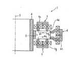
磁気軸受装置1 におけるロータ4 は、略円筒形状の筐体2 内に収納され、回転軸3 の下方端付近に円盤4aを取り付けている。またこの円盤4aの上下面には、隙間を介して磁極を対向させることによりロータ4 のスラスト方向(回転軸3 の軸方向)および傾き方向(回転軸3 の傾き方向)に対してロータ4 を非接触に支持するための上部電磁石5a,5b,5c,5d および下部電磁石5e,5f,5g,5h (但し、5fと5hは図示せず)が設けられている。これら上部電磁石5a,5b,5c,5d および下部電磁石5e,5f,5g,5h はスラスト磁気軸受5 を構成している。またロータ4 の円盤4aの外周面には、隙間を介して磁極を対向させることによりロータ4 のラジアル方向(回転軸3 と直交する方向)に対して非接触に支持するための電磁石6a,6b,6c,6d が設けられている。これら電磁石6a,6b,6c,6d はラジアル磁気軸受6を構成している。
【0017】
また筐体2 内の上部電磁石5a,5b,5c,5d の上方には、ロータ4 を回転駆動するための電動機7 が設けられている。
ロータ4 の円盤4a外周側には、回転軸3 の軸方向に貫通し半径方向に沿って等間隔に形成されたスリット(導電性調節手段)8 が、ここでは計36本設けられている。
【0018】
図3は、スラスト磁気軸受5 およびラジアル磁気軸受6 の磁束の流れを説明するための図であり、スラスト磁気軸受5 の上部電磁石5cと下部電磁石5gおよびラジアル磁気軸受6 の電磁石6cのみを拡大して示している。
【0019】
これらスラスト磁気軸受5 の上部電磁石5cと下部電磁石5gおよびラジアル磁気軸受6 の電磁石6cは、ロータ4 の円盤4aに設けたそれぞれのスリット8 が形成する面に対してほぼ平行な面内で磁路を形成することになる。つまり、スラスト磁気軸受5 の上部電磁石5cの磁束M1は、円盤4aの半径方向に対して外側から内側に流れ、上部電磁石5cと円盤4aとの隙間を通って電磁石ヨークに入り、閉ループを構成している。また、スラスト磁気軸受5 の下部電磁石5gの磁束M2は、円盤4aの半径方向に対して内側から外側に流れ、下部電磁石5gと円盤4aとの隙間を通って電磁石ヨークに入り、閉ループを構成している。さらに、ラジアル磁気軸受6 の電磁石6cの磁束M3は、円盤4aの軸方向に対して上側から下側に流れ、電磁石6cと円盤4aとの隙間を通って電磁石ヨークに入り、閉ループを構成している。これらM1,M2,M3が形成する面は、スリット8 が形成する面とほぼ平行である。
【0020】
スラスト磁気軸受5 の上部電磁石5a,5b,5dと下部電磁石5e,5f,5hおよびラジアル磁気軸受6 の電磁石6a,6b,6dについてはここでは図示していないが、図3と同様に磁束の流れが形成される。
【0021】
次に、本発明における導電性調節手段、すなわち円盤4aにスリット8 を設けることによる作用を説明する。
本発明において円盤4aにスリット8 を設けた理由は、ロータ4 の円盤4aが電動機7 で回転駆動された時に発生する鉄損、特に渦電流損を低減させるためである。
【0022】
つまり、仮にスリット8 が形成されていない状態を考えた場合、円盤4aは電動機7 で回転駆動されると、スラスト磁気軸受5 の上部電磁石5a,5b,5c,5d と下部電磁石5e,5f,5g,5h 、およびラジアル磁気軸受6 の電磁石6a,6b,6c,6d の磁極部に対向する上下面および外周面には、渦電流損が発生する。この渦電流損は、周方向に分割して配置されたスラスト磁気軸受5 およびラジアル磁気軸受6 の磁束が、周方向に対して一様ではなく分布してしまうために発生する。
【0023】
従来の磁気軸受装置では、この渦電流損を低減するために積層継鉄が広く用いられている。しかし、積層継鉄を用いた渦電流損低減の方法はラジアル磁気軸受に対しては有効に働くが、スラスト磁気軸受に対してはその効果は期待できない。そこで本発明では、渦電流損がロータ4 の回転に伴って発生することに着目し、スリット8 を設けた円盤4aを回転させるとともに、その周囲にラジアル磁気軸受とスラスト磁気軸受を配置した。
【0024】
ロータ4 の回転に伴い、スラスト磁気軸受5 およびラジアル磁気軸受6 に起因して円盤4aには渦電流が誘起されるが、この渦電流は円盤4aに設けたスリット8 で遮られる。これは、スリット8 が形成されているために円盤4aの周方向に磁束が移動しないことに起因している。したがって、渦電流の発生を抑制することが可能となる。
【0025】
このように構成された本実施形態の磁気軸受装置1 では、導電性調節手段であるスリット8 を設けたことにより、渦電流損の低減のための積層継鉄を使用することなくロータ4 の円盤4aの上下部と外周部にスラスト磁気軸受5 およびラジアル磁気軸受6 を配置することができる。したがって、ラジアル磁気軸受をその軸方向に複数配置した従来の磁気軸受装置に比べて軸方向長さが短くコンパクトな構成となる。
【0026】
また、積層継鉄を用いる必要がなくなるため、筐体2 内に露出する積層継鉄の端面が錆びることによる筐体内の汚染を防止することができる。
また、積層継鉄を用いた場合に問題となる遠心力および熱膨張差変形に起因するアンバランスを除去または低減できるので、ロータ4 の回転運動特性を向上でき、さらに大口径ロータを用いることが容易となる。
【0027】
なお、図2では電動機7 をスラスト磁気軸受5 の上部電磁石5a,5b,5c,5d の上側に設けた構成となっているが、例えばスラスト磁気軸受5 の下部電磁石5e,5f,5g,5h の下側に設けた構成であってもよい。さらに、図3ではスラスト磁気軸受5 の上部電磁石5cと下部電磁石5gおよびラジアル磁気軸受6 の電磁石6cの磁束M1,M2,M3が記載されているが、磁束の流れが逆向きとなるように電磁石を制御しても、本発明の効果を期待することができる。
【0028】
続いて、図4を参照して本発明の第2の実施形態を説明する。なお、以下に説明する各実施形態において第1の実施形態と同一構成要素には同一符号を付し、重複する説明を省略する。
【0029】
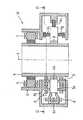
図4は本発明の第2の実施形態に係る磁気軸受装置10の側断面図である。
本実施形態における磁気軸受装置10の特徴は、筐体2 がロータ4 の内部空間に挿入されるべく挿入部2aを設け、この挿入部2aに電動機7 を取り付けることにより、電動機7 をロータ4 の内周部に配置した点にある。そのため、図示のようにラジアル磁気軸受6 と電動機7 を回転軸3 の軸方向に対して同じ高さの位置に配置することが可能となる。
【0030】
このような構成の第2の実施形態によれば、第1の実施形態に比べて軸方向長さが短くなり、コンパクトな磁気軸受装置を提供することができる。
続いて、図5を参照して本発明の第3の実施形態を説明する。図5は本発明の第3の実施形態に係る磁気軸受装置20の側断面図である。本実施形態における磁気軸受装置20の特徴は、筐体2 の挿入部2aの形状を図4に示したものから変形し、この挿入部2aにラジアル磁気軸受6 を取り付けることにより、ラジアル磁気軸受6 をロータ4 の円盤4aの内周部に配置した点にある。なお、電動機7 はロータ4 の外周部に配置されている。そのため、図示のようにラジアル磁気軸受6 と電動機7 を回転軸3 の軸方向に対して同じ高さの位置に配置することが可能となる。
【0031】
このような構成の第3の実施形態によれば、先の実施形態と同様に軸方向長さが短くなり、コンパクトな磁気軸受装置を提供することができる。
図6は、本発明の磁気軸受装置1 におけるスラスト磁気軸受5 およびラジアル磁気軸受6 の変位センサ配置を説明する側断面図、図7は図6におけるB−B線断面図である。ここで、図6に示した側断面図は図7中のC−C線断面図に相当するものである。
【0032】
スラスト磁気軸受5 に用いるスラスト変位センサ11a,11b,11c,11d は、ロータ4 の円盤4aの上面に対して空隙を介した状態で筐体2 に等間隔に固定されている。これらスラスト変位センサ11a,11b,11c,11d は、円盤4aの内周付近上面(スリット8 が形成されていない部分)を検出し、図示しないスラスト変位センサ変換器および信号処理回路によってロータ4 の軸方向変位および傾き方向変位を求める。これらスラスト変位センサ11a,11b,11c,11d の変位信号に基づき、図示しない制御部からの制御信号によってスラスト磁気軸受5 が位置決め制御される。
【0033】
また、ラジアル磁気軸受6 に用いるラジアル変位センサ12a,12b は、円盤4aの上部でロータ4 の外周面に対して空隙を介した状態で、90°の位相差をもって筐体2 に固定されている。これらラジアル変位センサ12a,12b は、ロータ4 の外周面を検出し、図示しないラジアル変位センサ変換器および信号処理回路によってロータ4 の半径方向変位を求める。これらラジアル変位センサ12a,12b の変位信号に基づき、図示しない制御部からの制御信号によってラジアル磁気軸受6 が位置決め制御される。
【0034】
なお、図6においてスラスト変位センサ11a,11b,11c,11d は、ロータ4 の円盤4aの上面に対して空隙を介した状態で筐体2 に固定されているが、円盤4aの下面に空隙を介した状態で筐体2 に固定しても良い。また、ラジアル変位センサ12a,12b は、円盤4aの上部でロータ4 の外周面に対して空隙を介した状態で筐体2 に固定されているが、円盤4aの下部でロータ4 の外周面、またはロータ4 の内周面に対して空隙を介した状態で筐体2 に固定しても良い。
【0035】
また、ここではスラスト変位センサの数は4個、ラジアル変位センサの数は2個の例を示したが、スラスト変位センサの数は3個以上、ラジアル変位センサの数は2個以上設けることにより、装置に必要となる空間5自由度を確実に検出することができる。
【0036】
図8は、本発明の磁気軸受装置30におけるスラスト磁気軸受5 およびラジアル磁気軸受6 の変位センサ配置を説明する側断面図、図9は図8におけるD−D線断面図である。ここで、図8に示した側断面図は図9中のE−E線断面図に相当するものである。
【0037】
スラスト磁気軸受5 に用いるスラスト変位センサ13a,13b,13c,13d,13e,13f,13g,13h (但し13e,13f,13h は図示せず)は、ロータ4 の円盤4aの上面および下面に対して空隙を介した状態で筐体2 に等間隔に固定されている。これらスラスト変位センサ13a,13b,13c,13d,13e,13f,13g,13h は、円盤4aの上面(スリット8 が形成されている部分)を検出し、図示しないスラスト変位センサ変換器および信号処理回路によってロータ4 の軸方向変位および傾き方向変位を求める。これらスラスト変位センサ13a,13b,13c,13d,13e,13f,13g,13h の変位信号に基づき、図示しない制御部からの制御信号によってスラスト磁気軸受5 が制御される。
【0038】
また、ラジアル磁気軸受6 に用いるラジアル変位センサ14a,14b,14c,14d は、円盤4aの外周側面に対して空隙を介した状態で、90°の位相差をもって筐体2 に固定されている。これら変位センサ14a,14b,14c,14d は、円盤4aの外周側面を検出し、図示しないラジアル変位センサ変換器および信号処理回路によってロータ4 の半径方向変位を求める。こららラジアル変位センサ14a,14b,14c,14d の変位信号に基づき、図示しない制御部からの制御信号によってラジアル磁気軸受6 が位置決め制御される。
【0039】
なお、図8および図9ではスラスト変位センサ13a,13b,13c,13d,13e,13f,13g,13h は、ロータ4 の円盤4aの上下面に空隙を介した状態で筐体2 に固定されているが、円盤4aの上下面にそれぞれ同一平面を形成するように少なくとも3組以上のスラスト変位センサを配置すれば良い。
【0040】
図10は、図8および図9に示す磁気軸受装置30のラジアル変位センサ14a,14c の差動出力信号を説明するための図である。ロータ4 が回転駆動すると、ラジアル変位センサ14a,14c の出力信号は回転同期成分の振動波形31a,32a と、ロータ4 の円盤4aに設けたスリット8 がラジアル変位センサ14a,14c の検出位置を通過する度に発生するパルス状の振動波形31b,32b が重畳した出力波形31,32 となる。このパルス状の振動波形31b,32b は、ロータ4 の振動変位とは関係なく、スリット8 の影響で発生する誤差信号である。
【0041】
そのため、ラジアル変位センサ14a の出力信号31またはラジアル変位センサ14c の出力信号32を使用してラジアル磁気軸受6 を浮上制御すると、ロータ4 の回転駆動に伴ってパルス状の振動波形31b または32b に起因した振動が発生し、ロータ4 の浮上特性が劣化する。そこで、両者の出力信号31,32 の差動信号33を浮上制御に用いることにより、スリット8 の影響で発生するパルス状の振動波形31b,32b を除去または低減することができ、良好な浮上特性が維持される。
【0042】
さらに、円盤4aの遠心力および熱膨張変形に起因する検出誤差を小さくできると共に、ラジアル変位センサの検出感度が2倍に向上することになるので、より高精度で安定性の高い磁気軸受装置が提供される。
【0043】
また、図10はラジアル変位センサ14a,14c の差動信号を説明するための図であるが、ラジアル変位センサ14b と14d およびスラスト変位センサ13a と13e 、13b と13f 、13c と13g 、13d と13h の組で同様に差動信号を生成し、それら差動信号を用いてラジアル磁気軸受6 とスラスト磁気軸受5 が制御することも可能である。
【0044】
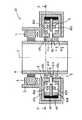
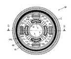
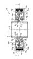
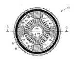
続いて、図11および図12を参照して本発明の第4の実施形態を説明する。図11は本発明の第4実施形態に係る磁気軸受装置40の側断面図であり、図12は図11中のF−F線断面図である。ここで、図11に示した側断面図は図12中のG−G線断面図に相当するものである。また、図13および図14はスラスト磁気軸受およびラジアル磁気軸受の磁束の流れを説明するための図であり、それぞれ図11および図12に対応して描かれている。
【0045】
本実施形態における磁気軸受装置40は、筐体2 内に収納され回転軸3 の下方端付近に円盤4aを設けたロータ4 と、この円盤4aの上下面には、隙間を介して磁極を対向させることによりロータ4 のスラスト方向および傾き方向に対してロータ4 を非接触に支持するための上部電磁石41a,41b,41c,41d および下部電磁石41e,41f,41g,41h (但し、41f と41h は図示せず)が設けられている。これら上部電磁石41a,41b,41c,41d および下部電磁石41e,41,41g,41hはスラスト磁気軸受5 を構成している。また、ロータ4 の円盤4aの外周面には、隙間を介して磁極を対向させることによりロータ4 のラジアル方向に対して非接触に支持するための電磁石42a,42b,42c,42d が設けられている。これら電磁石42a,42b,42c,42d はラジアル磁気軸受6 を構成している。
【0046】
また筐体2 内の上部電磁石41a,41b,41c,41d の上方には、ロータ4 を回転駆動する電動機7 が設けられている。
ロータ4 の円盤4a外周側には、回転軸3 の軸方向に貫通し半径方向に沿って等間隔に形成されたスリット8 が、ここでは計36本設けられている。このスリット8 は、第1の実施形態の場合と同様、ロータ4 の円盤4aが電動機7 で回転駆動された時に発生する鉄損、特に渦電流損を低減する働きをする。
【0047】
さらに本実施形態では、ロータ4 の回転軸3 を中心として筐体2 に同心円状に装着された2個の環状磁石43a,43b が配置されている。これら環状磁石43a,43b は回転軸3 の軸方向に対して互いに逆向きに着磁され、互いに対向する側の一端面がラジアル磁気軸受6 の磁極42a,42b,42c,42d と磁気的に接続されている。一方、環状磁石43a,43b の他端面はスラスト磁気軸受5 の上部磁極41a,41b,41c,41d および下部磁極41e,41f,41g,41h にそれぞれ磁気的に接続されている。
【0048】
また、スラスト磁気軸受5 の上部磁極41a,41b,41c,41d と下部磁極41e,41f,41g,41h は、筐体2 に同心円状に装着された環状継鉄部44によって磁気的に接続されている。
【0049】
さらに、ラジアル磁気軸受6 の磁極42a,42b,42c,42d は、周方向に90°の位相差をもって筐体2 に固定されており、その位置から回転軸3 の方向に突出した形状をなしている。ラジアル磁気軸受6 の磁極42a,42b,42c,42d は、全体として略環状の磁極リング46を構成すると共に、筐体2 に同心円状に装着され環状継鉄部44の内側に内挿された非磁性材製(例えばアルミニウムやステンレス)からなる支持部材45に固定されている。
【0050】
また、スラスト磁気軸受5 の上部磁極41a,41b,41c,41d および下部磁極41e,41f,41g,41h にはそれぞれ制御コイル47a,47b,47c,47d と47e,47f,47g,47h (但し、47f と47h は図示せず)が巻装されており、同様にラジアル磁気軸受6 の磁極42a,42b,42c,42d には制御コイル48a,48b,48c,48d が巻装されている。
【0051】
図13に示されるように、環状磁石43a,43b から発生した磁束M4a,M4b は、ラジアル磁気軸受6 の磁極42a,42b,42c,42d を通り、スラスト磁気軸受5 の上部磁極41a,41b,41c,41d と下部磁極41e,41f,41g,41h を通る閉ループを構成している。
【0052】
ここで、例えばロータ4 が半径方向に対して図13の左方向に変位して図中左側の半径方向空隙長が狭くなった場合には、その狭くなった空隙を通過する磁束(吸引力)を弱め、図中右側の広くなった半径方向空隙長の磁束を通過する磁束(吸引力)を強くするように制御コイル48a,48c に電流を印加することで、ロータ4 には図中右方向に磁気力が作用して安定化される。
【0053】
また、図14に示されるように、制御コイル48a,48c が作る磁束M5は磁極42a →磁極リング46→磁極42c →円盤4aを通る閉ループを構成している。そしてその結果、磁極42a を通る磁束M4a,M4b と磁束M5とは互いに逆向きに流れて打消し合い、磁極42c を通る磁束M4a,M4b と磁束M5は同じ向きに流れて強め合うことにより、上述した制御コイルによる半径方向の安定化浮上制御が達成される。
【0054】
同様に、制御コイル48b,48d 間を移動する磁束に関しても、上述した制御コイル48a,48c の場合と同様に、磁束が強め合うことにより安定に浮上制御される。また、例えばロータ4 が軸方向に対して図13の下方に変位し、図中下側の軸方向空隙長が小さくなった場合には、その空隙部の磁束(吸引力)を弱め、図中上側の広くなった軸方向空隙長の磁束(吸引力)を強くするように制御コイル47a,47b,47c,47d,47e,47f,47g,47h に電流を印加することで、ロータ4 には図中上方への磁気力が作用して安定化される。
【0055】
ここで、制御コイル47a,47e が作る磁束M6a は磁極41a →環状継鉄部44→磁極41e →円盤4aを通る閉ループを構成している。そしてその結果、磁極41e を通る磁束M4b と磁束M6a とは互いに逆向きに流れて打消し合い、磁極41a を通る磁束M4a と磁束M6a は同じ向きに流れて強め合うことにより、上述した制御コイルによる軸方向の安定化浮上制御が達成される。
【0056】
同様に制御コイル47b,47f が作る磁束M6b (図示せず)、制御コイル47c,47g が作る磁束M6c 、制御コイル47d,47h が作る磁束M6d (図示せず)によっても軸方向の安定化浮上制御が達成されると共に、磁束M6a,M6b,M6c,M6d が独立に制御されているので、ロータ4 の傾き方向に対しても安定化が実現される。
【0057】
なお、各制御コイルの入力端は図示しない安定化浮上制御装置の出力端に接続されている。この安定化浮上制御装置は、例えば公知のゼロパワー制御方式を採用したものを採用することが可能であり、図示しない変位センサの出力信号を導入して各制御コイルの電流または電圧を制御するように構成されている。
【0058】
なお、本発明の磁気軸受装置は上述した各実施形態に限定されるものではなく、その趣旨を逸脱しない範囲で種々変形して実施できることは言うまでもない。たとえば、上記各実施形態では、導電性調節手段として円盤4aにスリット8 を設けたものを説明したが、本発明はこの形態以外の方法でも実現することができる。その1つとして、「異方性導電材料」を用いる方法がある。「異方性導電材料」としては、例えば日立化成工業株式会社から販売される日立異方導電フィルム「アニソルム(AC−2101)」や、東芝ケミカル株式会社から販売される異方性導電ペースト「XAPシリーズ」を挙げることができる。これらの材料は、円盤4aの表面に貼付または塗布し、電気を流す必要のある方向に対して圧力を付与することにより、その方向にのみ導電性を持たせることができる特性を有している。したがって、本発明の場合には、先のスリット8 を形成した方向とは異なる方向に圧力を付与して導電性に異方性を持たせれば、スリットを形成した場合と同様の効果を期待でき、導電性調節手段として十分に機能させることができる。
【0059】
また、本実施形態の説明ではスリット8 の数を36本に設定したものを示したが、本発明はこの本数に限定されるものではない。スリット8 の数が増加した場合、ロータ4 の回転に伴って生じる鉄損、特に渦電流損は低下するため、回転特性は向上する。しかし、ロータ4 の円盤4aの機械的強度は低下してしまう。したがって、スリット8 の数や間隔は電動機7 の容量やロータ4 の許容発熱量、円盤4aの機械的強度、回転数、スリット8 の形状等によって最適値が定まり、実際の設計で任意に決定されるものである。本発明では、単に1本のスリットを設けるだけでも従来以上の効果を得ることができる。
【0060】
また、上記各実施形態では、円盤4aに対してスリット8 を形成した例のみを示したが、ロータと円盤とを一体的に成形し、そこにスリットを形成してもよい。この場合、導電性調整手段はスリットのみということになる。
【0061】
また、上記各実施形態では、スリットはラジアル方向およびスラスト方向に沿った状態で形成されたもののみを示したが、本発明はこれ以外の方向にスリットを形成した場合にも効果を期待することができる。つまり本発明では円盤4aの表面に発生する渦電流がその回転方向に移動することを防止する必要があるが、例えばスリットをロータ半径方向からやや傾斜させた状態(渦巻き状)に形成しても、渦電流の低減に寄与することができる。すなわちスリットの形成角度は設計に応じて任意に設定することが可能である。
【0062】
また、上記各実施形態では、円盤4aに対してスリットを形成することにより導電性調整手段を構成した例のみを示したが、板状に形成された複数の部材をロータの周囲に所定間隔で接合し、全体として円盤状に形成しても本発明の効果を期待することができる。
【0063】
【発明の効果】
以上説明したように本発明によれば、従来のものに比べて回転軸方向に短く、装置内部の汚染を低減することが可能な磁気軸受装置が実現する。
【図面の簡単な説明】
【図1】本発明の磁気軸受装置の第1の実施形態に係る側断面図。
【図2】図1におけるA−A線断面図。
【図3】スラスト磁気軸受およびラジアル磁気軸受の磁束の流れを説明するための図。
【図4】本発明の第2の実施形態に係る磁気軸受装置の側断面図。
【図5】本発明の第3の実施形態に係る磁気軸受装置の側断面図。
【図6】磁気軸受装置におけるスラスト磁気軸受およびラジアル磁気軸受の変位センサ配置を説明する側断面図。
【図7】図6におけるB−B線断面図。
【図8】磁気軸受装置におけるスラスト磁気軸受およびラジアル磁気軸受の変位センサ配置の他の例を説明する側断面図。
【図9】図8におけるD−D線断面図。
【図10】図8および図9に示す磁気軸受装置30のラジアル変位センサ14a,14c の差動出力信号を説明するための図。
【図11】本発明の第4実施形態に係る磁気軸受装置の側断面図。
【図12】図11のF−F線断面図。
【図13】スラスト磁気軸受およびラジアル磁気軸受の磁束の流れを図11で示した断面から説明するための図。
【図14】スラスト磁気軸受およびラジアル磁気軸受の磁束の流れを図12で示した断面から説明するための図。
【図15】従来の磁気軸受装置を示す側断面図。
【符号の説明】
1,10,120,30,40 磁気軸受装置
2 筐体
3 回転軸
4 ロータ
4a 円盤
5 スラスト磁気軸受
6 ラジアル磁気軸受
7 電動機
8 スリット(導電性調節手段)[0001]
BACKGROUND OF THE INVENTION
The present invention relates to a magnetic bearing device.
[0002]
[Prior art]
At present, in a device such as a chemical vapor deposition apparatus (CVD apparatus) for growing a thin film of a predetermined component on a semiconductor substrate (wafer), a ball bearing is mainly used as a bearing apparatus for rotating and supporting a rotor.
[0003]
Such a chemical vapor deposition apparatus requires operation in a depressurized and clean atmosphere. Therefore, in the conventional apparatus constituted by using ball bearings as constituent elements, there is a problem that the lubricating oil of the ball bearings diffuses to foul the thin film formed on the wafer and reduce the product yield. . Further, when rust is generated in the ball bearing, a clean atmosphere is contaminated, and the generated rust causes galling in the bearing, which may make it impossible to rotate the rotor stably. In such a case, the ball bearing needs to be replaced, but it takes a lot of time for the replacement.
[0004]
Therefore, it has been studied to use a magnetic bearing device instead of using a ball bearing as a component. Since magnetic bearing devices have features such as non-contact, non-lubrication, and long life, various researches and application developments are being promoted in various fields.
[0005]
A conventional magnetic bearing device is configured, for example, as shown in FIG. The magnetic bearing
[0006]
The radial
[0007]
Further, a displacement sensor (not shown) is provided in the casing 91, and the displacement sensor detects the displacement in the axial direction and the radial direction of the rotor 93. Based on this, control from a control unit (not shown) is performed. The thrust magnetic bearing 94 and the radial
[0008]
In the conventional magnetic bearing device configured as described above, a thrust magnetic bearing 94,
[0009]
[Problems to be solved by the invention]
As described above, in the conventional magnetic bearing device, since the radial magnetic bearings are arranged in a plurality of locations in the axial direction of the rotating shaft, the device is long in the axial direction. Further, there is a possibility that the inside of the housing may be contaminated by rusting of the end face of the laminated yoke exposed in the housing.
Accordingly, an object of the present invention is to provide a magnetic bearing device in which the axial length of the rotating shaft is shorter than that of the conventional one and the contamination inside the device can be reduced.
[0010]
[Means for Solving the Problems]
In order to achieve the above object, according to the present invention, a rotatable rotor, rotational drive means for rotationally driving the rotor around a predetermined axis, and the rotor are arranged around the rotor, and the rotor is fixed by the magnetic attraction force. A plurality of electromagnets supported in a non-contact manner with respect to the axial direction and the direction orthogonal thereto, and an anisotropic conductive material affixed or applied to the surface of the rotor,Opposing to the plurality of electromagnetsSuch that the eddy current induced by the rotation of the rotor is blocked in the circumferential direction of the rotor.Apply pressure in the direction,The magnetic bearing device is characterized by comprising conductivity adjusting means that is formed by imparting anisotropy to the conductivity and makes the conductivity discontinuous with respect to the rotation direction of the rotor.
[0011]
Here, the conductivity adjusting means isThe peripheral surface facing the plurality of electromagnets and the predetermined axial direction are penetrated.It may be a formed slit or an anisotropic conductive material.
[0012]
Further, in the present invention, a rotatable rotor, a rotation driving means for rotating the rotor around a predetermined axis, a magnetic member attached to the outer peripheral surface of the rotor, and the magnetic member around the rotor A plurality of electromagnets disposed in a non-contact manner with respect to the predetermined axial direction and a direction orthogonal to the predetermined axial direction by a magnetic attractive force, and provided in the magnetic member, A magnetic bearing device having a slit that forms a surface including a direction orthogonal to the rotation axis was obtained.
[0015]
DETAILED DESCRIPTION OF THE INVENTION
Hereinafter, embodiments of the present invention will be described with reference to the drawings.
FIG. 1 is a side sectional view according to the first embodiment of the magnetic bearing device of the present invention, and FIG. 2 is a sectional view taken along line AA in FIG.
[0016]
The
[0017]
An
A total of 36 slits (conductivity adjusting means) 8 are provided on the outer peripheral side of the
[0018]
FIG. 3 is a diagram for explaining the flow of magnetic flux in the thrust
[0019]
The
[0020]
The
[0021]
Next, the effect of providing the
The reason why the
[0022]
In other words, if the state in which the
[0023]
In conventional magnetic bearing devices, laminated yokes are widely used to reduce this eddy current loss. However, the eddy current loss reduction method using the laminated yoke works effectively for the radial magnetic bearing, but the effect cannot be expected for the thrust magnetic bearing. Therefore, in the present invention, focusing on the fact that eddy current loss occurs with the rotation of the
[0024]
As the
[0025]
In the magnetic bearing device 1 of the present embodiment configured as described above, by providing the
[0026]
Further, since there is no need to use a laminated yoke, it is possible to prevent contamination within the casing due to rusting of the end face of the laminated yoke exposed in the
In addition, since unbalance due to centrifugal force and thermal expansion differential deformation, which is a problem when using laminated yokes, can be eliminated or reduced, the rotational motion characteristics of the
[0027]
In FIG. 2, the
[0028]
Next, a second embodiment of the present invention will be described with reference to FIG. In each embodiment described below, the same components as those in the first embodiment are denoted by the same reference numerals, and redundant description is omitted.
[0029]
FIG. 4 is a sectional side view of the
A feature of the
[0030]
According to the second embodiment having such a configuration, the axial length is shorter than that of the first embodiment, and a compact magnetic bearing device can be provided.
Subsequently, a third embodiment of the present invention will be described with reference to FIG. FIG. 5 is a sectional side view of a
[0031]
According to the third embodiment having such a configuration, the axial length is shortened similarly to the previous embodiment, and a compact magnetic bearing device can be provided.
FIG. 6 is a side sectional view for explaining the arrangement of displacement sensors of the thrust
[0032]
[0033]
Further, the
[0034]
In FIG. 6, the
[0035]
In this example, the number of thrust displacement sensors is four and the number of radial displacement sensors is two. However, the number of thrust displacement sensors is three or more, and the number of radial displacement sensors is two or more. Thus, it is possible to reliably detect the five degrees of freedom required for the device.
[0036]
FIG. 8 is a side sectional view for explaining the displacement sensor arrangement of the thrust
[0037]
[0038]
Further, the
[0039]
In FIGS. 8 and 9, the
[0040]
FIG. 10 is a diagram for explaining the differential output signals of the radial displacement sensors 14a and 14c of the
[0041]
Therefore, if the radial
[0042]
Furthermore, the detection error due to the centrifugal force and thermal expansion deformation of the
[0043]
FIG. 10 is a diagram for explaining the differential signals of the radial displacement sensors 14a and 14c. The
[0044]
Subsequently, a fourth embodiment of the present invention will be described with reference to FIG. 11 and FIG. FIG. 11 is a side sectional view of a
[0045]
The
[0046]
An
A total of 36
[0047]
Furthermore, in the present embodiment, two
[0048]
Further, the upper
[0049]
Further, the
[0050]
The upper
[0051]
As shown in FIG. 13, the magnetic fluxes M4a, M4b generated from the
[0052]
Here, for example, when the
[0053]
Further, as shown in FIG. 14, the magnetic flux M5 generated by the
[0054]
Similarly, with respect to the magnetic flux moving between the control coils 48b and 48d, as in the case of the
[0055]
Here, the magnetic flux M6a generated by the
[0056]
Similarly, the axially stabilized levitation control is also performed by the magnetic flux M6b (not shown) generated by the control coils 47b and 47f, the magnetic flux M6c generated by the control coils 47c and 47g, and the magnetic flux M6d (not shown) generated by the control coils 47d and 47h. Is achieved, and the magnetic fluxes M6a, M6b, M6c, and M6d are independently controlled, so that stabilization is achieved even in the tilt direction of the
[0057]
The input end of each control coil is connected to the output end of a stabilized levitation control device (not shown). As this stabilized levitation control device, for example, a device adopting a known zero power control method can be adopted, and an output signal of a displacement sensor (not shown) is introduced to control the current or voltage of each control coil. It is configured.
[0058]
The magnetic bearing device of the present invention is not limited to the above-described embodiments, and it goes without saying that various modifications can be made without departing from the spirit thereof. For example, in each of the embodiments described above, the
[0059]
In the description of this embodiment, the number of
[0060]
In each of the above embodiments, only the example in which the
[0061]
Moreover, in each said embodiment, although the slit showed only what was formed in the state along a radial direction and a thrust direction, this invention expects an effect also when a slit is formed in directions other than this. Can do. In other words, in the present invention, it is necessary to prevent the eddy current generated on the surface of the
[0062]
In each of the above embodiments, only the example in which the conductivity adjusting means is configured by forming a slit in the
[0063]
【The invention's effect】
As described above, according to the present invention, a magnetic bearing device that is shorter in the direction of the rotation axis than the conventional one and can reduce contamination inside the device is realized.
[Brief description of the drawings]
FIG. 1 is a side sectional view according to a first embodiment of a magnetic bearing device of the present invention.
FIG. 2 is a cross-sectional view taken along line AA in FIG.
FIG. 3 is a view for explaining the flow of magnetic flux of a thrust magnetic bearing and a radial magnetic bearing.
FIG. 4 is a side sectional view of a magnetic bearing device according to a second embodiment of the present invention.
FIG. 5 is a side sectional view of a magnetic bearing device according to a third embodiment of the present invention.
FIG. 6 is a side sectional view for explaining the arrangement of displacement sensors of a thrust magnetic bearing and a radial magnetic bearing in the magnetic bearing device.
7 is a sectional view taken along line BB in FIG.
FIG. 8 is a side sectional view for explaining another example of the displacement sensor arrangement of the thrust magnetic bearing and the radial magnetic bearing in the magnetic bearing device.
9 is a sectional view taken along line DD in FIG. 8. FIG.
10 is a diagram for explaining differential output signals of radial displacement sensors 14a and 14c of the
FIG. 11 is a side sectional view of a magnetic bearing device according to a fourth embodiment of the present invention.
12 is a sectional view taken along line FF in FIG.
13 is a view for explaining the flow of magnetic flux in the thrust magnetic bearing and the radial magnetic bearing from the cross section shown in FIG.
14 is a view for explaining the flow of magnetic flux of the thrust magnetic bearing and the radial magnetic bearing from the cross section shown in FIG. 12;
FIG. 15 is a side sectional view showing a conventional magnetic bearing device.
[Explanation of symbols]
1,10,120,30,40 Magnetic bearing device
2 Enclosure
3 Rotating axis
4 Rotor
4a disc
5 Thrust magnetic bearing
6 Radial magnetic bearing
7 Electric motor
8 Slit (conductivity adjustment means)
Claims (1)
Translated fromJapanese前記ロータの周囲に配置され、前記ロータを磁気吸引力により前記所定の軸方向およびそれと直交する方向に対して非接触に支持する複数の電磁石と、
前記ロータの表面に貼付または塗布された異方性導電材料の、前記複数の電磁石と対向する面に、前記ロータの回転に伴い誘起される渦電流を前記ロータの周方向に遮るような方向に圧力を付与して、導電性に異方性をもたせることによって形成され、前記ロータの回転方向に対して導電性を非連続的な状態にする導電性調節手段と、
を有することを特徴とする磁気軸受装置。A rotatable rotor, and rotation driving means for rotating the rotor about a predetermined axis;
A plurality of electromagnets disposed around the rotor and supporting the rotor in a non-contact manner with respect to the predetermined axial direction and a direction perpendicular thereto by a magnetic attractive force;
Of a patch or coated anisotropic conductive material to the surface of therotor,said plurality of electromagnets opposed tothat plane, the directionsuch as to block in the circumferential direction of the eddy currents induced in accordance with the rotation of the rotor the rotor and by applying pressureis formed by to have anisotropic conductivity, the conductive adjustment means for the electrically conductive with respect to the direction of rotation of the rotor in a non-continuous state,
A magnetic bearing device comprising:
Priority Applications (2)
| Application Number | Priority Date | Filing Date | Title |
|---|---|---|---|
| JP13282798AJP4024382B2 (en) | 1998-05-15 | 1998-05-15 | Magnetic bearing device |
| US09/310,585US6268674B1 (en) | 1998-05-15 | 1999-05-12 | Magnetic bearing apparatus |
Applications Claiming Priority (1)
| Application Number | Priority Date | Filing Date | Title |
|---|---|---|---|
| JP13282798AJP4024382B2 (en) | 1998-05-15 | 1998-05-15 | Magnetic bearing device |
Related Child Applications (1)
| Application Number | Title | Priority Date | Filing Date |
|---|---|---|---|
| JP2004375438ADivisionJP4406357B2 (en) | 2004-12-27 | 2004-12-27 | Magnetic bearing device |
Publications (2)
| Publication Number | Publication Date |
|---|---|
| JPH11325073A JPH11325073A (en) | 1999-11-26 |
| JP4024382B2true JP4024382B2 (en) | 2007-12-19 |
Family
ID=15090478
Family Applications (1)
| Application Number | Title | Priority Date | Filing Date |
|---|---|---|---|
| JP13282798AExpired - Fee RelatedJP4024382B2 (en) | 1998-05-15 | 1998-05-15 | Magnetic bearing device |
Country Status (2)
| Country | Link |
|---|---|
| US (1) | US6268674B1 (en) |
| JP (1) | JP4024382B2 (en) |
Families Citing this family (38)
| Publication number | Priority date | Publication date | Assignee | Title |
|---|---|---|---|---|
| JP4024382B2 (en)* | 1998-05-15 | 2007-12-19 | 株式会社東芝 | Magnetic bearing device |
| EP1223357B1 (en)* | 1999-09-30 | 2011-04-20 | Mitsubishi Denki Kabushiki Kaisha | Thrust magnetic bearing |
| JP2001182746A (en)* | 1999-12-27 | 2001-07-06 | Ebara Corp | Magnetic bearing device |
| US6806605B1 (en)* | 2001-05-13 | 2004-10-19 | Indigo Energy, Inc. | Permanent magnetic bearing |
| US6608418B2 (en)* | 2001-08-24 | 2003-08-19 | Smiths Aerospace, Inc. | Permanent magnet turbo-generator having magnetic bearings |
| JP3949916B2 (en)* | 2001-09-26 | 2007-07-25 | 日本電産サンキョー株式会社 | Magnetic levitation motor and magnetic bearing device |
| JP4557245B2 (en)* | 2003-10-17 | 2010-10-06 | 国立大学法人東京工業大学 | Motor device for artificial heart |
| EP1939473B1 (en)* | 2006-12-29 | 2018-05-23 | Rieter CZ s.r.o. | The method of leviation, centering, stabilization and driving of electromagnetic functional part of radial electromagnetic bearing and electrical ratation drive, electromagnetic bearing and driving system and spinning mechnism of rotor spinning machine |
| US8319385B2 (en)* | 2007-08-14 | 2012-11-27 | Rothe Erde Gmbh | Method and bearing for supporting rotatable devices, particularly a medical scanner |
| JP4934140B2 (en)* | 2008-01-29 | 2012-05-16 | 株式会社イワキ | Magnetic levitation motor and pump |
| DE102008017984A1 (en)* | 2008-04-07 | 2009-10-08 | Rothe Erde Gmbh | Magnetic bearing and method for producing a suitable bearing ring |
| DE102008034552A1 (en)* | 2008-07-24 | 2010-02-04 | Siemens Aktiengesellschaft | Magnetic bearing element i.e. bearing disk, for e.g. axial bearing, has rectilineal grooves provided in base surface using micro-operation process and radially and continuously extending from middle shaft passage to outer edge |
| JP5074331B2 (en)* | 2008-09-16 | 2012-11-14 | 川崎重工業株式会社 | Thrust magnetic bearing device |
| BE1019128A3 (en) | 2009-11-06 | 2012-03-06 | Atlas Copco Airpower Nv | LAMELATED CORE OF A MAGNETIC BEARING AND METHOD FOR PRODUCING SUCH LAMELATED CORE. |
| MX2012014398A (en) | 2010-06-08 | 2013-06-24 | Temporal Power Ltd | Flywheel energy system. |
| JP2012060754A (en)* | 2010-09-08 | 2012-03-22 | Ebara Corp | Magnetic levitation type rotation introduction apparatus |
| CN102400926A (en)* | 2010-09-14 | 2012-04-04 | 富泰华工业(深圳)有限公司 | Magnetic suspension-type fan |
| CN102280950B (en)* | 2011-07-20 | 2013-02-27 | 北京交通大学 | A Stator Structure for Motor Weakening and Speed Regulation |
| EP2607731B1 (en)* | 2011-12-19 | 2014-10-15 | Siemens Aktiengesellschaft | Magnetic radial bearing with radial laminated rotor |
| KR20130073200A (en)* | 2011-12-23 | 2013-07-03 | 삼성전기주식회사 | Spindle motor |
| CA2813020A1 (en) | 2012-04-16 | 2013-10-16 | Temporal Power Ltd. | Method and system for regulating power of an electricity grid system |
| BE1020693A3 (en) | 2012-05-16 | 2014-03-04 | Atlas Copco Aipower Nv | MAGNETIC BEARING AND METHOD FOR MOUNTING A FERROMAGNETIC STRUCTURE AROUND A CORE OF A MAGNETIC BEARING. |
| US9853525B2 (en)* | 2012-06-12 | 2017-12-26 | Abb Research Ltd. | Magnetic bearing assembly and arrangement of position sensors for a magnetic bearing assembly |
| JP6069693B2 (en)* | 2012-09-05 | 2017-02-01 | 株式会社明電舎 | 3-axis active control type magnetic bearing |
| EP2914826B1 (en) | 2012-11-05 | 2019-10-30 | BC New Energy (Tianjin) Co., Ltd. | Cooled flywheel apparatus |
| US9134141B2 (en) | 2012-12-06 | 2015-09-15 | Industrial Technology Research Institute | Measurement device |
| EP2887022B1 (en)* | 2013-12-20 | 2016-09-07 | Skf Magnetic Mechatronics | Rotor sensor target for magnetic bearings |
| US9083207B1 (en) | 2014-01-10 | 2015-07-14 | Temporal Power Ltd. | High-voltage flywheel energy storage system |
| CN104141685B (en)* | 2014-08-06 | 2017-11-03 | 杭州中俊科技有限公司 | The main passive internal rotor magnetic bearing of one kind |
| CN104121288B (en)* | 2014-08-06 | 2017-10-24 | 赛特勒斯轴承科技(北京)有限公司 | The main passive outer rotor magnetic bearing of one kind |
| CN104121290B (en)* | 2014-08-06 | 2017-12-12 | 国网浙江省电力公司丽水供电公司 | A kind of internal rotor magnetic bearing |
| CN105736568B (en)* | 2016-04-29 | 2018-12-14 | 江苏众志达新能源科技有限公司 | A kind of magnetic suspension bearing voluntarily pre-tightened |
| US9945418B1 (en)* | 2016-07-31 | 2018-04-17 | Rotor Bearings Solutions International, LLC | Thrust and radial magnetic bearings using combined electromagnetic and permanent magnetic flux paths |
| JP6696855B2 (en)* | 2016-08-01 | 2020-05-20 | 株式会社Ihi | Magnetic bearing |
| CN107448475B (en)* | 2017-07-31 | 2019-06-11 | 北京航空航天大学 | An integrated structure of a three-degree-of-freedom magnetic bearing and an eddy current sensor |
| EP3683464B1 (en) | 2019-01-21 | 2022-03-02 | Ingersoll-Rand Industrial U.S., Inc. | Active magnetic bearing apparatus |
| WO2020183884A1 (en)* | 2019-03-14 | 2020-09-17 | 株式会社イワキ | Magnetic bearing, drive device equipped with same, and pump |
| JP7544707B2 (en)* | 2019-07-19 | 2024-09-03 | 株式会社イワキ | pump |
Family Cites Families (25)
| Publication number | Priority date | Publication date | Assignee | Title |
|---|---|---|---|---|
| DE2248695A1 (en)* | 1972-10-04 | 1974-04-11 | Skf Kugellagerfabriken Gmbh | BEARING FOR SHAFTS ROTATING AT HIGH SPEED |
| US4000929A (en)* | 1975-07-03 | 1977-01-04 | The United States Of America As Represented By The United States National Aeronautics And Space Administration | Magnetic bearing system |
| JPS5233011A (en) | 1975-09-10 | 1977-03-12 | Hitachi Ltd | Structure of permanent magnet i body of revolution |
| US4077678A (en)* | 1976-07-30 | 1978-03-07 | The United States Of America As Represented By The Administrator Of The National Aeronautics And Space Administration | Energy storage apparatus |
| US4180296A (en)* | 1978-01-06 | 1979-12-25 | Societe Europeenne De Propulsion | Axial electromagnetic bearing for a shaft rotating at high speed |
| JPS58149899A (en)* | 1982-02-26 | 1983-09-06 | 三菱電機株式会社 | Magnetic bearing wheel for artificial satellite attitude control |
| FR2524090A1 (en)* | 1982-03-26 | 1983-09-30 | Aerospatiale | MAGNETIC SUSPENSION DEVICE FOR INERTIA WHEEL |
| JPS6014931A (en) | 1983-07-04 | 1985-01-25 | Kaneda Kosakusho:Kk | White smoke generating device |
| FR2586070B1 (en)* | 1985-08-12 | 1987-12-18 | Europ Propulsion | LARGE DIAMETER RADIAL MAGNETIC BEARING |
| JPH0198708A (en)* | 1987-10-07 | 1989-04-17 | Ebara Res Co Ltd | Radial magnetic bearing device |
| US4940878A (en)* | 1988-12-15 | 1990-07-10 | Westinghouse Electric Corp. | Anisotropic resistivity material and method of making same |
| US4920291A (en)* | 1989-01-19 | 1990-04-24 | Contraves Goerz Corporation | Magnetic thrust bearing with high force modulation capability |
| US5216308A (en)* | 1989-05-25 | 1993-06-01 | Avcon-Advanced Controls Technology, Inc. | Magnetic bearing structure providing radial, axial and moment load bearing support for a rotatable shaft |
| US4983870A (en)* | 1989-07-26 | 1991-01-08 | Contraves Goerz Corporation | Radial magnetic bearing |
| GB2246401B (en)* | 1990-07-28 | 1994-05-11 | Glacier Metal Co Ltd | Magnetic bearings |
| JP2699706B2 (en) | 1991-07-26 | 1998-01-19 | 三菱電機株式会社 | Industrial robot equipment |
| DE4208039C2 (en)* | 1992-03-13 | 2002-01-17 | Schlafhorst & Co W | Pot spinning device |
| US5514924A (en)* | 1992-04-30 | 1996-05-07 | AVCON--Advanced Control Technology, Inc. | Magnetic bearing providing radial and axial load support for a shaft |
| DE4301076A1 (en)* | 1993-01-16 | 1994-07-21 | Forschungszentrum Juelich Gmbh | Magnetic bearing cell with rotor and stator |
| US5543673A (en)* | 1993-07-27 | 1996-08-06 | Sundstrand Corporation | High performance magnetic bearing |
| US6310414B1 (en)* | 1994-06-21 | 2001-10-30 | Rotoflow Corporation | Shaft bearing system |
| CH688515A5 (en)* | 1994-07-23 | 1997-10-31 | Traxler Alfons Dr | Vacuum centrifuge and seal here for. |
| US5547350A (en)* | 1994-12-15 | 1996-08-20 | Dresser-Rand Company | Modular shaftless compressor |
| JPH11101233A (en)* | 1997-09-26 | 1999-04-13 | Nippon Seiko Kk | Magnetic bearing device |
| JP4024382B2 (en)* | 1998-05-15 | 2007-12-19 | 株式会社東芝 | Magnetic bearing device |
- 1998
- 1998-05-15JPJP13282798Apatent/JP4024382B2/ennot_activeExpired - Fee Related
- 1999
- 1999-05-12USUS09/310,585patent/US6268674B1/ennot_activeExpired - Fee Related
Also Published As
| Publication number | Publication date |
|---|---|
| US6268674B1 (en) | 2001-07-31 |
| JPH11325073A (en) | 1999-11-26 |
Similar Documents
| Publication | Publication Date | Title |
|---|---|---|
| JP4024382B2 (en) | Magnetic bearing device | |
| US6114788A (en) | Motor/active magnetic bearing combination structure | |
| JP4427938B2 (en) | Thrust magnetic bearing device | |
| JP2011239661A (en) | Linear rotary actuator | |
| JP3675772B2 (en) | Stepping motor | |
| EP0687827A1 (en) | Hybrid magnetic/foil gas bearings | |
| CN101218446B (en) | Magnetic bearing of a rotor shaft relative to a stator, and rotor and stator disk elements inserted into one another | |
| JP2009192041A (en) | Thrust force generator and electromagnetic machine to which the thrust force generator is applied | |
| KR20060121355A (en) | Bearingless Step Motor | |
| JP2005098520A (en) | Magnetic bearing device | |
| JP3930834B2 (en) | Axial type magnetic levitation rotating equipment and centrifugal pump | |
| JP2004003572A (en) | Magnetic bearing and bearing device provided with it | |
| JPH0921420A (en) | Magnetic bearing device for high-speed rotating machinery | |
| JP2004316756A (en) | 5-axis control magnetic bearing | |
| JPH04219494A (en) | Structure of magnetic bearing for high speed rotary vacuum pump | |
| JPH08186953A (en) | Spindle equipment | |
| JPH0371569B2 (en) | ||
| JPH063375B2 (en) | Flex gyroscope | |
| JPH05344674A (en) | Motor bearing device | |
| JPH01103146A (en) | Motor | |
| JPH05111231A (en) | Swing action type voice coil motor | |
| JPS6353315A (en) | Bearing device for rotary shaft | |
| JPS5854284B2 (en) | magnetic bearing | |
| JPS5854285B2 (en) | Five-axis controlled magnetic bearing | |
| JPH0591710A (en) | Linear motor for swing operation |
Legal Events
| Date | Code | Title | Description |
|---|---|---|---|
| A977 | Report on retrieval | Free format text:JAPANESE INTERMEDIATE CODE: A971007 Effective date:20040730 | |
| A131 | Notification of reasons for refusal | Free format text:JAPANESE INTERMEDIATE CODE: A131 Effective date:20040806 | |
| A521 | Written amendment | Free format text:JAPANESE INTERMEDIATE CODE: A523 Effective date:20041005 | |
| A02 | Decision of refusal | Free format text:JAPANESE INTERMEDIATE CODE: A02 Effective date:20041112 | |
| A521 | Written amendment | Free format text:JAPANESE INTERMEDIATE CODE: A523 Effective date:20041227 | |
| A911 | Transfer of reconsideration by examiner before appeal (zenchi) | Free format text:JAPANESE INTERMEDIATE CODE: A911 Effective date:20050106 | |
| A912 | Removal of reconsideration by examiner before appeal (zenchi) | Free format text:JAPANESE INTERMEDIATE CODE: A912 Effective date:20050311 | |
| RD02 | Notification of acceptance of power of attorney | Free format text:JAPANESE INTERMEDIATE CODE: A7422 Effective date:20050415 | |
| RD04 | Notification of resignation of power of attorney | Free format text:JAPANESE INTERMEDIATE CODE: A7424 Effective date:20050606 | |
| A521 | Written amendment | Free format text:JAPANESE INTERMEDIATE CODE: A523 Effective date:20070910 | |
| A61 | First payment of annual fees (during grant procedure) | Free format text:JAPANESE INTERMEDIATE CODE: A61 Effective date:20071003 | |
| FPAY | Renewal fee payment (event date is renewal date of database) | Free format text:PAYMENT UNTIL: 20101012 Year of fee payment:3 | |
| LAPS | Cancellation because of no payment of annual fees |