JP4023401B2 - Counterpart position display device - Google Patents
Counterpart position display deviceDownload PDFInfo
- Publication number
- JP4023401B2 JP4023401B2JP2003184897AJP2003184897AJP4023401B2JP 4023401 B2JP4023401 B2JP 4023401B2JP 2003184897 AJP2003184897 AJP 2003184897AJP 2003184897 AJP2003184897 AJP 2003184897AJP 4023401 B2JP4023401 B2JP 4023401B2
- Authority
- JP
- Japan
- Prior art keywords
- vehicle
- opponent
- partner
- information
- current position
- Prior art date
- Legal status (The legal status is an assumption and is not a legal conclusion. Google has not performed a legal analysis and makes no representation as to the accuracy of the status listed.)
- Expired - Fee Related
Links
Images


Landscapes
- Navigation (AREA)
- Traffic Control Systems (AREA)
- Mobile Radio Communication Systems (AREA)
- Instructional Devices (AREA)
Description
Translated fromJapanese【0001】
【発明の属する技術分野】
本発明は、相手車から相手車の位置情報を取得し自車で相手車位置を表示する相手車位置表示装置に関する。
【0002】
【従来の技術】
【特許文献1】
特開2000−331284号公報
従来の相手車位置表示装置としては、例えば特開2000−331284号公報に開示されているように、それぞれの車両に備えたGPS(Global Positioning System)により各車両で自車の位置情報を取得し、携帯電話及びPHS(Personal Handyphone System)を用いて相手車に送信し、受信した車両で相手車の位置を地図上で表示するナビゲーションシステムにおけるグループ位置表示装置が知られている。
【0003】
【発明が解決しようとする課題】
しかしながら、上記従来の装置においては、相手車の位置情報の取得に携帯電話及びPHSを用いるため、例えば複数の車両がグループ走行時に相手車の位置を常時、表示する必要がある場合、通信コストが高価になってしまう。
そこで、コストフリーの狭域通信を用いる方法が考えられるが、この場合は、通信エリアが狭く、使用できる範囲が限定されてしまうといった問題がある。
本発明は、上記従来の問題点に鑑み、狭域通信を用いても、その通信範囲に制限されることなく、より広範囲で相手車の位置表示ができる相手車位置表示装置を提供することを目的としている。
【0004】
【課題を解決するための手段】
本発明は、狭域通信手段を用いて、相手車から相手車の位置情報と車速情報を受信し、地図上で相手車の位置表示を行うとともに、相手車が狭域通信エリアから外れた場合、受信した相手車の車速情報を用いて、相手車の現在位を推定して地図上で表示させる。
この際、推定された相手車の現在位置の範囲を地図上で表示し、相手車が狭域通信エリアから外れている期間で、自車の位置と推定する相手車の現在位置の範囲が重なった場合に、基地局を介して無線通信を行う移動通信手段を用いて相手車の位置情報を取得し、推定した相手車の現在位置に対して補正をかけるようにした。
【0005】
【発明の効果】
本発明によれば、相手車が狭域通信エリアから外れた場合、受信した相手車の車速を用いて相手車の現在位置を推定して表示するようにしたから、相手車位置の表示可能な範囲は、狭域通信エリアに制限されず、より広域に表示することが可能になる。これによって、複数の車両がグループ走行時に、車両位置は狭域通信エリアを超えた位置関係にあっても、互いに車両位置を確認することができる。この際、推定した相手車の現在位置範囲と自車位置が重なったことをトリガとして、相手車から位置情報を取得するようにしたから、より高精度に相手車の位置推定ができる。
【0006】
【発明の実施の形態】
次に、発明の実施の形態を実施例により説明する。
本実施例では、車載機を搭載した自車と相手車がグループ走行時に行われる車両位置表示について説明する。
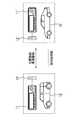
図1は、自車と相手車がグループ走行中の相手車位置表示に関する情報のやりとりを示す概念図である。
すなわち、自車10と相手車10’は、それぞれに備えられた車載機11と車載機11’が互いに狭域通信機12、狭域通信機12’を介して自車の位置情報と車速情報を相手に送信し、相手の車両位置情報を取得する。自車10では、受信した相手車10’の車両位置情報に基づいて、地図上で相手車10’の位置を表示する。相手車10’も同様に、地図上で自車10の位置を表示する。
【0007】
情報の送受信は、車両位置を表示している間に連続して行われるが、狭域通信エリアから相手車10’が外れて、狭域通信機12と狭域通信機12’の通信リンクが切断され、情報が行き渡らないような状況では、自車10は、受信した相手車10’の車速情報を用いて相手車の位置を推定して表示する。相手車10’も同様に、自車10の位置を推定して表示する。
【0008】
図2は、車載機の構成を示す図である。
車載機11の位置検出部201は、ジャイロ、GPS(Global Positioning System)などを用いて自車の現在位置を検出する。
車速モニタ202は、自車の車速をモニタする。
送受信部203は、狭域通信機12とのインタフェースであり、ある所定の時間毎に、相手車に対して自車位置情報及び自車車速情報を送信し、また相手車10’から相手車位置情報及び相手車車速情報を受信する。相手車10’から受信した情報は、時刻情報と共にメモリ204に格納される。狭域通信機12、狭域通信機12’としては、例えば通信コストフリーの無線LANを用いる。
【0009】
狭域通信モニタ205は、自車10の狭域通信機12から相手車10’の狭域通信機12’に対してリンク確立用のpingコマンドを送信してリンク確立を確認する方法等を用いて、相手車10’が狭域通信エリア内にいるか、エリア外にいるかを判定する。
相手車位置推定部206は、相手車10’が狭域通信エリア外に存在するとき、メモリ204に格納されている車速情報等を用いて相手車10’の位置を推定する。
【0010】
データ生成部207は、自車10の位置情報に基づいて、地図データベース(DB)208から、自車位置を含む地図情報を抽出する。抽出された地図情報に、自車位置情報と相手車位置情報を用いて、自車位置と相手車位置を重畳させて地図データを生成する。相手車位置情報としては、相手車が狭域通信エリア内の場合、メモリ204に格納されている相手車位置情報を用い、狭域通信エリア外の場合には、相手車位置推定部206で推定された相手車位置推定情報を用いる。
表示部209は、生成された画像データに基づいて自車位置と相手車位置を含んだ地図を表示しドライバに提示する。
【0011】
図3は、車載機における相手車の位置表示を行うための手順を示すフローチャートである。
ここで、自車と相手車は、通信するためのIPアドレス等宛先情報をそれぞれ持っているものとする。
ステップ100において、イグニッションスイッチがオンになったか否かをチェックし、オンになると、ステップ110へ進む。
ステップ110では、位置検出部201からの自車位置情報、及び車速モニタ202からの自車車速情報を、送受信部203を介して狭域通信機12より、相手車に送信する。この送信は、所定時間毎に行われる。
【0012】
ステップ120において、送受信部203は相手車から送信された相手車位置情報、及び相手車車速情報を受信する。
ステップ130において、受信した相手車の相手車位置情報と車速情報を受信時刻情報と共にメモリ204に格納する。
ステップ140において、データ生成部207は、メモリ204から相手車位置情報を呼び出して、相手車位置を地図情報に重畳させた画像データを生成する。
ステップ150において、表示部209は生成された画像データに基づいて自車位置および相手車位置を含んだ地図画像の表示を行ってドライバに提示する。
【0013】
ステップ160において、イグニッションスイッチがオフになったか否かを判定しオフでない場合は、ステップ170へ進む。一方、オフになった場合には、相手車位置を含めて地図画像の表示を終了する。
ステップ170では、通信モニタ205は、自車の狭域通信機12から相手車の通信機に対してpingコマンドを送信してリンクの確立を行うことによって、相手車が狭域通信エリア内にいるか、また狭域通信エリア外にいるかを判定する。
【0014】
相手車が狭域通信エリア内にいた場合は、ステップ110に戻り、上記の動作を繰り返す。ステップ170の判断で相手車が狭域通信エリア外にいた場合には、ステップ180へ進む。
ステップ180においては、相手車位置推定部206はメモリ204に格納されていた相手車車速情報を用いて、例えば相手車の進行方向上で現在位置を推定する。
相手車車速情報としては、時間的に最も新しい情報を用いてもよく、出発してからの平均車速を用いても構わない。
【0015】
ステップ190において、データ生成部207は、推定された相手車の推定位置を地図情報に重畳させた画像データを生成する。
ステップ195において、表示部209は、生成された画像データに基づいて推定された相手車の位置を含んだ地図画像の表示を行ってドライバに提示する。
相手車の位置表示としては、例えば相手車位置を示すアイコンを所定の円形の枠で囲み、枠の大きさで相手車位置がある可能な範囲を示す。
また、この枠は、例えば相手車の位置推定を開始してからの時間経過に比例して拡大させていくこともできる。
【0016】
その後、ステップ160に戻って、イグニッションスイッチがオフであるかの判断を経て、再び相手車が狭域通信エリア内か否かについての判断を行う。狭域通信エリア内である場合、ステップ110に戻り、そうでない場合には、ステップ180へ進む。
これによって、相手車が狭域通信エリア外に存在する間、相手車位置推定が繰り返され、推定された相手車位置が表示される。相手車が再び狭域通信エリア内に戻れば、狭域通信機12によって、相手車から相手車位置情報と相手車車速情報を取得して、相手車の実際の位置を表示する。
【0017】
図4は、狭域通信エリアから外れた相手車の位置を推定して表示するイメージ図である。
図中、30は自車を示すアイコン、31は相手車を示すアイコンである。32は、相手車の存在するであろう範囲を示す枠である。枠の直径は例えば地図の比例に合わせて設定する。
33は、相手車の位置推定に関する情報を示す。なお、ここでは相手車との推定距離、及び相手車の位置を推定開始してから経過した時間を表示している。
【0018】
図5は、相手車位置推定経過時間に比例して相手車の存在するであろう範囲を示す枠を拡大させて表示する場合のイメージ図である。
30は自車を示すアイコン、31、31a、31b、31cは、相手車を示すアイコンである。
32、32a、32b、32cは、相手車の存在するであろう範囲を示す枠である。最小の枠32の直径は任意に設定することができるが、その後の枠32a、32b、32cは、推定経過時間が経つほど拡大させていく。図では、各現在位置の推定する時間間隔が10秒で、10秒経つ毎に、枠の直径が1.2倍になるようになっている。
【0019】
本実施例は、以上のように構成され、車載機11と狭域通信機12を備える自車10と相手車10’がグループ走行において、相手車10’が狭域通信機12による狭域通信エリアから外れた場合に、それまでに受信した車速情報を用いて相手車10’の現在位置を推定して表示する。これにより、相手車位置の表示可能な範囲が拡大され、グループ走行をしているドライバが相手車と離れてしまった場合でも、相手車の位置確認ができ安心して追従することができる。特に、右左折や加減速の機会が少ない高速道路で利用する場合、高い精度で推定することが可能である。
【0020】
なお、相手車位置の推定において、例えば相手車から目的地情報を受信し、相手車の走行経路を計算し、走行経路上で相手車位置を推定することも可能で、この場合より正確な相手車位置を求めることができる。
また、例えば交通情報取得装置を設け、車両外部より渋滞情報、また地図データベース208が格納する信号位置情報を、相手車の車速情報に加味すれば、さらに正確な相手車位置を推定することができる。
本実施例では、ステップ180が、現在位置推定手段を構成している。
ステップ190、ステップ195が表示手段を構成している。
【0021】
次に、第2の実施例について説明する。
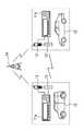
図6は、自車と相手車がグループ走行中の相手車位置表示に関する情報のやりとりを示す概念図である。
第2の実施例では、自車10と相手車10’との間で、通信を行うための通信手段として無線LANで構成される狭域通信機12、狭域通信機12’のほか携帯電話、車載電話または通信機能内蔵モジュール等公衆通信網を用いる移動通信機13、移動通信機13’を備える。
【0022】
したがって、自車10と相手車10’は、狭域通信のほか、基地局14を介した無線通信を行うことが可能になっている。狭域通信機12、狭域通信機12’による狭域通信エリアから相手車10’が外れて、相手車位置を推定するときには、自車10の車載機11aは、移動通信機13、移動通信機13’を通じて相手車10’の車載機11a’から、相手車の位置情報を取得し推定時の誤差を補正するようにした。
狭域通信を行う狭域通信機12、狭域通信機12’による通信が行えるときは、第1の実施例と同様に、狭域通信機12、狭域通信機12’を用いて相手車10’とを通信を行って、相手車10’の位置情報と相手車10’の速度情報を取得して画像表示を行う。これについては、第1の実施例と同様であり説明を省略する。
【0023】
図7は、狭域通信エリアから相手車が外れたときの車両位置の推定および表示の流れを示すフローチャートである。
なお、ここでは自車と相手車は、互いに通信するための電話番号、及びIPアドレス等宛先情報を持っているものとする。
本フローチャートのスタートは、図3のフローチャートにおけるステップ170のチェックで相手車10’が狭域通信エリア内からエリア外に変移した時点とする。
【0024】
ステップ200において、相手車位置推定部206’(図2参照)は、タイマをセットしてカウントアップを開始する。
ステップ210からステップ230までの動作は、図3のステップ180、ステップ190、ステップ195と同じである。すなわち、メモリ204に格納されていた相手車車速情報を用いて、相手車の現在位置を推定し、データ生成部207は、推定された相手車の推定位置を地図情報に重畳させた画像データを生成し、表示部209に、生成された画像データに基づいて推定された相手車の位置を含んだ地図画像の表示を行ってドライバに提示する。
【0025】
この後、ステップ240において、狭域通信モニタ205は、相手車が狭域通信エリアから外れていることを確認し、外れ続けている場合、ステップ250において、相手車位置推定部206’は、タイマ値と予め定められた時間の閾値を比較する。
タイマ値がその閾値以下であれば、ステップ210に戻り、上記の処理、すなわち相手車の車速情報を用いて相手車位置推定を繰り返す。
【0026】
タイマ値がその閾値よりも大きければ、相手車位置推定部206’は、相手車位置の誤差が大きくなっていると判断し、ステップ260に進む。
ステップ260では、送受信部203により移動通信機13を介して相手車位置情報を取得する。これによって、相手車10’の位置が補正される。
ステップ270において、移動通信機13によって得られた相手車の位置情報を用いて、相手車位置を重畳させた画像データを生成する。
ステップ280において、生成された画像データに基づき、実際の相手車位置を含んだ画像提示を行う。
【0027】
その後は、ステップ200へ戻り、取得した車両位置から、相手車位置推定が行われる。したがって、長時間の推定で推定誤差が拡大することがなくなる。
なお、ステップ240で相手車が狭域通信エリアに復帰したと判断すると、図3のステップ110に戻り、受信した相手車10’の位置情報に基づいて位置表示を行う。
【0028】
本実施例によれば、ある時間の閾値を境に、相手車10’の位置情報を取得することによって、狭域通信エリアから外れた相手車10’の位置推定をより正確に行うことができる。
相手車に対して移動通信機13を介して位置情報の送信を要求するトリガとしては、所定のタイマ値としたが、自車現在位置と相手車推定位置の距離でも置き換えることができる。これは、例えば図2の車載機11の構成に車車間距離モニタを備え、両車両の車間距離が予め定められた距離以上になった時点で相手車位置情報を要求することで実現することができる。
本実施例では、ステップ210、ステップ260が、現在位置推定手段を構成している。
ステップ220、ステップ230、ステップ270、ステップ280が表示手段を構成している。
【0029】
次に、第2の実施例の変形例について説明する。
まず、第1の変形例を説明する
ここでは、相手車10’が狭域通信エリアから外れている期間で、自車10の位置と推定する相手車10’の現在位置の範囲が重なったことをトリガとして、移動通信機13、移動通信機13’を用いて相手車10’の位置情報を基地局14を介して要求し、相手車10’の位置情報を取得する。
【0030】
図8は、変形例における狭域通信エリアから、相手車が外れたときの車両位置の推定および表示の流れを示すフローチャートである。
なお、自車と相手車は通信するための電話番号、及びIPアドレス等宛先情報を持っているものとする。
【0031】
本フローチャートのスタートは、図3のフローチャートにおけるステップ170のチェックで相手車10’が狭域通信エリア内からエリア外に変移した時点とする。
ステップ300において、相手車位置推定部206’’(図2参照)はタイマをリセットしてカウントアップを開始する。
ステップ310、320の動作は、図3のステップ180、ステップ190と同様である。すなわち、メモリ204に格納されていた相手車の車速情報を用いて、相手車10’の現在位置を推定し、データ生成部207は、推定された相手車10’の推定位置にアイコンを示した地図情報の画像データを生成する。
【0032】
ステップ330では、生成された画像データに、さらに図5に示したように、アイコン31を囲むように相手車10’が存在するであろう範囲を示す枠32を重ねた画像データを生成する。この枠32の大きさは、相手車位置の推定を開始してからの経過時間に比例して拡大される。
ステップ340において、表示部209は、ステップ330で生成された画像データに基づいて推定された相手車の位置範囲を示すアイコンと枠を含んだ地図画像の表示を行ってドライバに提示する。
【0033】
ステップ350において、狭域通信モニタ205は、相手車が狭域通信エリアから外れ続けていることを確認し、通信エリアから外れ続けている場合は、ステップ360において、相手車位置推定部206’’は、自車位置と相手車の位置範囲とを比較する。すなわち、自車の位置と相手車の現在位置範囲を示す枠が重なっていなければ、ステップ310に戻り、相手車の位置推定を繰り返す。
【0034】
自車の位置と枠が重なっていれば、相手車の位置の誤差が大きくなっていると判断し、ステップ370において、送受信部203は移動通信機13、移動通信機13’を介して相手車の位置情報を取得する。これによって、相手車の位置が補正される。
ステップ380において、データ生成部207は、移動通信機13によって得られた相手車位置の情報を用いて、相手車位置を重畳させた画像データを生成する。
ステップ390において、表示部209は、生成された画像データに基づいて相手車位置を含んだ地図画像表示を行う。
ステップ400において、相手車の現在位置範囲を示す枠の大きさをリセットして、最小値に戻す。
【0035】
その後は、ステップ300に戻り、再度相手車の位置推定を続ける。
なお、ステップ350で相手車が狭域通信エリアに復帰したと判断すると、図3のステップ110に戻り、受信した相手車10’の位置情報に基づいて位置表示を行う。
上記のように、推定した相手車の現在位置範囲と自車位置が重なったことをトリガとして、相手車から位置情報を取得するようにしたから、より高精度に相手車の位置推定ができる。
【0036】
次に、第2の変形例について説明する。
相手車10’が狭域通信装置12の通信エリアから外れている期間で、自車の車両情報に変化があったことをトリガとして、自車10と推定する相手車10’の位置関係に応じたメッセージを、移動通信機13を用いて自車の位置情報と共に送信する。
例えば、相手車の位置推定を行っている期間に、自車のパーキングブレーキのオンをトリガに、「ここに駐車しました」といったメッセージと位置情報を自動的に送信する。それを受信した相手車のドライバーは、歩調を合わせるために駐車を行い、あるいは先行している場合は速度を緩め、後続している場合は近い場所で駐車をする予定を立てることができる。
また、自車が先行車か後続車かを判断し、車両位置に応じたメッセージを自動的に送信する。例えば、先行車だった場合は「ここで駐車して待っているよ」、後続車だった場合は「ここで駐車をするので少し待っていてください」等である。
【0037】
以上より、自車の車両情報に変化があった場合、自車と推定する相手車の位置関係に応じたメッセージを自車の位置情報と共に基地局14を介した移動通信機13を用いて送信することで、両車両で状況に応じたコミュニケーションをとることができる。
変形例では、ステップ310、ステップ370が、現在位置推定手段を構成している。
ステップ320、ステップ330、ステップ380、ステップ390が表示手段を構成している。
【図面の簡単な説明】
【図1】自車と相手車がグループ走行中の相手車位置表示に関する情報のやりとりを示す概念図である。
【図2】車載機の構成を示す図である。
【図3】車載機における相手車の位置表示を行うための手順を示すフローチャートである。
【図4】狭域通信エリアから外れた相手車の位置を推定して表示するイメージ図である。
【図5】相手車位置推定経過時間に比例して相手車の存在するであろう範囲を示す枠を拡大させて表示する場合のイメージ図である。
【図6】第2の実施例における自車と相手車がグループ走行中の相手車位置表示に関する情報のやりとりを示す概念図である。
【図7】第2の実施例における狭域通信エリアから相手車が外れたときの車両位置の推定および表示の流れを示すフローチャートである。
【図8】変形例を示すフローチャートである。
【符号の説明】
10 自車
10’ 相手車
11、11’ 車載機
12、12’ 狭域通信機
13、13’ 移動通信機
14 基地局
201 位置検出部
202 車速モニタ
203 送受信部
204 メモリ
205 狭域通信モニタ
206 相手車位置推定部
207 データ生成部
208 地図データベース
209 表示部[0001]
BACKGROUND OF THE INVENTION
The present invention relates to an opponent vehicle position display device that acquires position information of an opponent vehicle from an opponent vehicle and displays the opponent vehicle position on the own vehicle.
[0002]
[Prior art]
[Patent Document 1]
JP, 2000-33284, A As a conventional partner vehicle position display device, for example, as disclosed in JP, 2000-33284, each vehicle uses its own GPS (Global Positioning System). A group position display device in a navigation system that acquires vehicle position information, transmits the information to a partner vehicle using a mobile phone and a PHS (Personal Handyphone System), and displays the position of the partner vehicle on a map by the received vehicle is known. ing.
[0003]
[Problems to be solved by the invention]
However, in the above conventional apparatus, since the mobile phone and the PHS are used to acquire the position information of the opponent vehicle, for example, when a plurality of vehicles need to always display the positions of the opponent vehicles when traveling in a group, the communication cost is low. It becomes expensive.
Thus, a method using cost-free narrow area communication is conceivable, but in this case, there is a problem that the communication area is narrow and the usable range is limited.
In view of the above-described conventional problems, the present invention provides a counterpart vehicle position display device that can display the location of a counterpart vehicle in a wider range without being limited to the communication range even when narrow-area communication is used. It is aimed.
[0004]
[Means for Solving the Problems]
The present invention receives the position information and speed information of the partner vehicle from the partner vehicle using the narrow area communication means, displays the position of the partner vehicle on the map, and the partner vehicle is out of the narrow area communication area. Using the received vehicle speed information of the partner vehicle, the current position of the partner vehicle is estimated and displayed on the map.
At this time, the range of the estimated current position of the partner vehicle is displayed on the map, and the range of the current position of the partner vehicle to be estimated overlaps with the position of the host vehicle in a period when the partner vehicle is out of the narrow area communication area. In this case, the position information of the opponent vehicle is acquired using mobile communication means that performs wireless communication via the base station, and the estimated current position of the opponent vehicle is corrected.
[0005]
【The invention's effect】
According to the present invention, when the partner vehicle departs from the narrow area communication area, the current position of the partner vehicle is estimated and displayed using the received vehicle speed of the partner vehicle, so that the partner vehicle position can be displayed. The range is not limited to the narrow communication area, and can be displayed in a wider area. Accordingly, when a plurality of vehicles are traveling in a group, the vehicle positions can be confirmed with each other even if the vehicle positions are in a positional relationship beyond the narrow area communication area.At this time, the position information of the opponent vehicle can be estimated with higher accuracy because the position information is acquired from the opponent vehicle triggered by the overlap of the estimated current position range of the opponent vehicle and the own vehicle position.
[0006]
DETAILED DESCRIPTION OF THE INVENTION
Next, embodiments of the present invention will be described by way of examples.
In the present embodiment, a description will be given of the vehicle position display that is performed when the host vehicle and the counterpart vehicle equipped with the in-vehicle device are traveling in a group.
FIG. 1 is a conceptual diagram showing an exchange of information related to a partner vehicle position display when the host vehicle and the partner vehicle are traveling in a group.
That is, the
[0007]
Information transmission / reception is continuously performed while the vehicle position is displayed, but the partner vehicle 10 'is removed from the narrow area communication area, and the communication link between the narrow
[0008]
FIG. 2 is a diagram illustrating a configuration of the in-vehicle device.
The
The
The transmission / reception unit 203 is an interface with the narrow
[0009]
The narrow
The partner vehicle
[0010]
The
The
[0011]
FIG. 3 is a flowchart showing a procedure for displaying the position of the opponent vehicle in the in-vehicle device.
Here, it is assumed that the own vehicle and the partner vehicle each have destination information such as an IP address for communication.
In
In
[0012]
In
In
In
In
[0013]
In
In
[0014]
If the partner vehicle is in the narrow communication area, the process returns to step 110 and the above operation is repeated. If it is determined in
In
As the opponent vehicle speed information, the latest information in time may be used, or the average vehicle speed after departure may be used.
[0015]
In
In
As the position display of the opponent vehicle, for example, an icon indicating the opponent vehicle position is surrounded by a predetermined circular frame, and the possible range of the opponent vehicle position is indicated by the size of the frame.
Further, this frame can be expanded in proportion to the passage of time since the start of the position estimation of the opponent vehicle, for example.
[0016]
Thereafter, the process returns to step 160, and after determining whether the ignition switch is OFF, it is determined again whether the opponent vehicle is in the narrow communication area. If it is within the narrow communication area, the process returns to Step 110, and if not, the process proceeds to Step 180.
As a result, while the opponent vehicle exists outside the narrow area communication area, the opponent vehicle position estimation is repeated, and the estimated opponent vehicle position is displayed. When the partner vehicle returns to the narrow area communication area again, the narrow
[0017]
FIG. 4 is an image diagram for estimating and displaying the position of the opponent vehicle outside the narrow area communication area.
In the figure, 30 is an icon indicating the own vehicle, and 31 is an icon indicating the opponent vehicle.
[0018]
FIG. 5 is an image diagram in a case where the frame indicating the range where the opponent vehicle will exist is enlarged and displayed in proportion to the estimated time of the opponent vehicle position.
30 is an icon indicating the own vehicle, and 31, 31a, 31b, and 31c are icons indicating the opponent vehicle.
32, 32a, 32b, and 32c are frames that indicate ranges in which the opponent vehicle will be present. The diameter of the
[0019]
The present embodiment is configured as described above, and the
[0020]
In estimating the partner vehicle position, for example, it is possible to receive destination information from the partner vehicle, calculate the travel route of the partner vehicle, and estimate the partner vehicle position on the travel route. The car position can be determined.
In addition, for example, if a traffic information acquisition device is provided and traffic congestion information from the outside of the vehicle or signal position information stored in the
In this embodiment,
Step 190 and step 195 constitute display means.
[0021]
Next, a second embodiment will be described.
FIG. 6 is a conceptual diagram showing the exchange of information regarding the display of the partner vehicle position when the host vehicle and the partner vehicle are traveling in a group.
In the second embodiment, the narrow
[0022]
Therefore, the
When communication can be performed by the narrow
[0023]
FIG. 7 is a flowchart showing the flow of estimation and display of the vehicle position when the opponent vehicle is removed from the narrow area communication area.
Here, it is assumed that the own vehicle and the partner vehicle have destination information such as a telephone number and an IP address for communicating with each other.
The start of this flowchart is the time when the opponent vehicle 10 'has changed from the inside of the narrow area communication area to the outside of the area by the check of
[0024]
In
The operations from
[0025]
Thereafter, in
If the timer value is equal to or less than the threshold value, the process returns to step 210, and the above process, that is, the opponent vehicle position estimation is repeated using the opponent vehicle speed information.
[0026]
If the timer value is larger than the threshold value, the opponent vehicle
In
In
In
[0027]
Thereafter, the process returns to step 200, and the opponent vehicle position is estimated from the acquired vehicle position. Therefore, the estimation error does not increase due to long-term estimation.
If it is determined in
[0028]
According to the present embodiment, by acquiring the position information of the
Although the predetermined timer value is used as a trigger for requesting the other vehicle to transmit position information via the
In this embodiment,
[0029]
Next, a modification of the second embodiment will be described.
First, the first modified example will be described. Here, the range of the current position of the
[0030]
FIG. 8 is a flowchart showing a flow of estimation and display of the vehicle position when the opponent vehicle is removed from the narrow area communication area in the modified example.
It is assumed that the own vehicle and the partner vehicle have destination information such as a telephone number for communication and an IP address.
[0031]
The start of this flowchart is the time when the opponent vehicle 10 'has changed from the inside of the narrow area communication area to the outside of the area by the check of
In
The operations of
[0032]
In
In
[0033]
In
[0034]
If the position of the host vehicle and the frame overlap, it is determined that the error in the position of the opponent vehicle has increased, and in
In
In
In
[0035]
Thereafter, the process returns to step 300, and the position estimation of the opponent vehicle is continued again.
If it is determined in
As described above, the position information of the opponent vehicle can be estimated with higher accuracy because the position information is acquired from the opponent vehicle triggered by the overlap of the estimated current position range of the opponent vehicle and the own vehicle position.
[0036]
Next, a second modification will be described.
Depending on the positional relationship between the
For example, during the period when the position of the opponent vehicle is being estimated, a message such as “I parked here” and position information are automatically transmitted with the parking brake of the own vehicle turned on as a trigger. The driver of the other vehicle who has received it can park to keep pace, or can slow down if ahead and schedule to park nearby if it follows.
Further, it determines whether the host vehicle is a preceding vehicle or a succeeding vehicle, and automatically transmits a message corresponding to the vehicle position. For example, if it is a preceding vehicle, “I will park and wait here”, and if it is a following vehicle, “I will park here and wait a bit”.
[0037]
As described above, when there is a change in the vehicle information of the own vehicle, a message corresponding to the positional relationship between the other vehicle to be estimated as the own vehicle is transmitted using the
In the modified example,
[Brief description of the drawings]
FIG. 1 is a conceptual diagram showing an exchange of information related to an opponent vehicle position display when a host vehicle and an opponent vehicle are traveling in a group.
FIG. 2 is a diagram illustrating a configuration of an in-vehicle device.
FIG. 3 is a flowchart showing a procedure for displaying the position of the opponent vehicle in the in-vehicle device.
FIG. 4 is an image diagram for estimating and displaying the position of a partner vehicle that is out of a narrow communication area.
FIG. 5 is an image diagram in the case of enlarging and displaying a frame indicating a range in which the opponent vehicle will exist in proportion to the estimated time of the opponent vehicle position.
FIG. 6 is a conceptual diagram showing an exchange of information related to a partner vehicle position display when the host vehicle and the partner vehicle are traveling in a group in the second embodiment.
FIG. 7 is a flowchart showing a flow of estimation and display of the vehicle position when the opponent vehicle is out of the narrow area communication area in the second embodiment.
FIG. 8 is a flowchart showing a modification.
[Explanation of symbols]
DESCRIPTION OF
Claims (6)
Translated fromJapanese前記相手車が狭域通信手段による狭域通信エリアから外れた場合、前記相手車の車速情報を用いて、前記相手車の現在位置を推定する現在位置推定手段と、
前記推定された相手車の現在位置の範囲を地図上で表示する表示手段と、
基地局を介して無線通信を行う移動通信手段とを備え、
前記現在位置推定手段は、
前記相手車が狭域通信エリアから外れている期間で、自車の位置と推定する相手車の現在位置の範囲が重なった場合、前記移動通信手段を用いて相手車の位置情報を取得し、推定した相手車の現在位置に対して補正をかける
ことを特徴とする相手車位置表示装置。In the partner vehicle position display device that acquires the position information and vehicle speed information of the partner vehicle from the partner vehicle using the narrow area communication means, and displays the position of the partner vehicle on the map,
A current position estimating means for estimating a current position of the opponent vehicle using vehicle speed information of the opponent vehicle when the opponent vehicle is out of a narrow area communication area by the narrow area communication means;
Display means for displaying on the map arange of the current position of the estimated counterpartvehicle,
Mobile communication means for performing wireless communication via a base station,
The current position estimating means includes
When the range of the current position of the opponent vehicle that is estimated as the position of the own vehicle overlaps in the period when the opponent vehicle is out of the narrow area communication area, the position information of the opponent vehicle is acquired using the mobile communication means, A partner vehicle position display devicethat corrects the estimated current position of the partner vehicle.
該ナビゲーションシステムに入力された相手車の目的地情報をさらに取得し、
前記現在位置推定手段は、前記車速情報に前記目的地情報を加えて、相手車の現在位置を推定する
ことを特徴とする請求項1記載の相手車位置表示装置。The partner vehicle is equipped with a navigation device,
Further acquiring destination information of the partner vehicle input to the navigation system,
2. The opponent vehicle position display device according to claim 1, wherein the current position estimating means estimates the current position of the opponent vehicle by adding the destination information to the vehicle speed information.
前記現在位置推定手段は、地図情報データベース内の地図情報と受信した交通情報を用いて、前記相手車の現在位置を推定する
ことを特徴とする請求項1または2記載の相手車位置表示装置。A traffic information receiving means for receiving a map information database and traffic information;
3. The partner vehicle position display device according to claim 1, wherein the current position estimating means estimates the current position of the partner vehicle using map information in the map information database and the received traffic information.
ことを特徴とする請求項1から4のいずれか1に記載の相手車位置表示装置。Before SL current position estimation means, the period of the counterpart vehicle is out of the narrow-area communication area, when it becomes larger than the predetermined prescribed time, obtains the position information of the counterpart vehicle by using the mobile communication means, 5. The opponent vehicle position display device according to claim 1, wherein a correction is applied to the estimated current position of the opponent vehicle.
ことを特徴とする請求項1から5のいずれか1に記載の相手車位置表示装置。When there is a change in the vehicle information of the own vehicle in a period when the opponent vehicle is out of the narrow area communication area, a message corresponding to the positional relationship of the opponent vehicle estimated as the own vehicle is sent using the mobile communication means. Send to car
The opponent vehicle position display device according toany one of claims 1 to 5, wherein:
Priority Applications (1)
| Application Number | Priority Date | Filing Date | Title |
|---|---|---|---|
| JP2003184897AJP4023401B2 (en) | 2003-06-27 | 2003-06-27 | Counterpart position display device |
Applications Claiming Priority (1)
| Application Number | Priority Date | Filing Date | Title |
|---|---|---|---|
| JP2003184897AJP4023401B2 (en) | 2003-06-27 | 2003-06-27 | Counterpart position display device |
Publications (2)
| Publication Number | Publication Date |
|---|---|
| JP2005017200A JP2005017200A (en) | 2005-01-20 |
| JP4023401B2true JP4023401B2 (en) | 2007-12-19 |
Family
ID=34184519
Family Applications (1)
| Application Number | Title | Priority Date | Filing Date |
|---|---|---|---|
| JP2003184897AExpired - Fee RelatedJP4023401B2 (en) | 2003-06-27 | 2003-06-27 | Counterpart position display device |
Country Status (1)
| Country | Link |
|---|---|
| JP (1) | JP4023401B2 (en) |
Families Citing this family (11)
| Publication number | Priority date | Publication date | Assignee | Title |
|---|---|---|---|---|
| JP4581767B2 (en)* | 2005-03-16 | 2010-11-17 | 株式会社デンソー | Communication device |
| JP4480613B2 (en)* | 2005-03-29 | 2010-06-16 | アルパイン株式会社 | Navigation device |
| JP4787139B2 (en)* | 2006-11-20 | 2011-10-05 | 東亜建設工業株式会社 | Throwing position management system |
| US8332142B2 (en) | 2006-12-26 | 2012-12-11 | Rohm Co., Ltd. | Position display apparatus |
| JP2008236052A (en)* | 2007-03-16 | 2008-10-02 | Rohm Co Ltd | Position display device |
| JP5014874B2 (en)* | 2007-05-11 | 2012-08-29 | ローム株式会社 | Position display device |
| EP2068120B1 (en)* | 2007-12-04 | 2010-08-11 | Research In Motion Limited | Mobile tracking |
| US8554243B2 (en) | 2007-12-04 | 2013-10-08 | Blackberry Limited | Mobile tracking |
| WO2010007539A1 (en)* | 2008-07-16 | 2010-01-21 | Autotalks Ltd. | Relative vehicular positioning using vehicular communications |
| JP5902076B2 (en)* | 2012-10-01 | 2016-04-13 | 本田技研工業株式会社 | Information processing apparatus, information processing method, and program |
| WO2018233602A1 (en) | 2017-06-19 | 2018-12-27 | Beijing Didi Infinity Technology And Development Co., Ltd. | SYSTEMS AND METHODS FOR DISPLAYING THE MOVEMENT OF A VEHICLE ON A CARD |
- 2003
- 2003-06-27JPJP2003184897Apatent/JP4023401B2/ennot_activeExpired - Fee Related
Also Published As
| Publication number | Publication date |
|---|---|
| JP2005017200A (en) | 2005-01-20 |
Similar Documents
| Publication | Publication Date | Title |
|---|---|---|
| CN106990415B (en) | Improved vehicle location service | |
| CN108632347B (en) | Method of detecting vehicle collision at vehicle and vehicle telematics apparatus | |
| US6871067B2 (en) | Method and system for communicating telematics messages | |
| US7254480B2 (en) | Communication-data relaying method and inter-vehicle communication system | |
| US20050065715A1 (en) | Method and apparatus for peripheral vehicle position calculation | |
| JP4023401B2 (en) | Counterpart position display device | |
| JP2010515905A (en) | Navigation apparatus and method for increasing transferred data | |
| US9198145B2 (en) | Wireless communication system | |
| CN102119319A (en) | Method and mobile device for finding a suitable boarding area on a platform | |
| JP2016167264A (en) | Method and test device of testing mobile radio communication support type emergency notification system | |
| WO2017195520A1 (en) | Vehicle control system and vehicle control device | |
| US20100161209A1 (en) | Routing a User to a Parked Vehicle | |
| KR100474705B1 (en) | Method for transmitting and receiving data between mobile station and information center in navigation system | |
| JP2008269358A (en) | Vehicle parking guidance device and parking guidance system | |
| US12414182B2 (en) | Communication terminal device, communication method and communication program product | |
| US12323847B2 (en) | Communication system, vehicle, server, method for controlling vehicle, and non-transitory storage medium | |
| JP2017173905A (en) | Communication control device for vehicle | |
| JP3864734B2 (en) | In-vehicle navigation device, navigation information providing device, and communication navigation system service providing method | |
| JP3948359B2 (en) | Navigation system and navigation device | |
| KR20170091288A (en) | Communication system and method between accident vehicles and other vehicles | |
| KR100706538B1 (en) | Location and Route Guidance using Telematics | |
| JP2000180187A (en) | Information display apparatus for vehicle and information-distributing apparatus | |
| JP2000182188A (en) | Information display device for vehicle and information distribution device | |
| JP2009265870A (en) | Driving support device and its display method | |
| WO2010001553A1 (en) | Wireless apparatus |
Legal Events
| Date | Code | Title | Description |
|---|---|---|---|
| A621 | Written request for application examination | Effective date:20060424 Free format text:JAPANESE INTERMEDIATE CODE: A621 | |
| A977 | Report on retrieval | Effective date:20070517 Free format text:JAPANESE INTERMEDIATE CODE: A971007 | |
| A131 | Notification of reasons for refusal | Free format text:JAPANESE INTERMEDIATE CODE: A131 Effective date:20070529 | |
| A521 | Written amendment | Free format text:JAPANESE INTERMEDIATE CODE: A523 Effective date:20070718 | |
| TRDD | Decision of grant or rejection written | ||
| A01 | Written decision to grant a patent or to grant a registration (utility model) | Free format text:JAPANESE INTERMEDIATE CODE: A01 Effective date:20070911 | |
| A61 | First payment of annual fees (during grant procedure) | Effective date:20070924 Free format text:JAPANESE INTERMEDIATE CODE: A61 | |
| R150 | Certificate of patent (=grant) or registration of utility model | Free format text:JAPANESE INTERMEDIATE CODE: R150 | |
| FPAY | Renewal fee payment (prs date is renewal date of database) | Free format text:PAYMENT UNTIL: 20101012 Year of fee payment:3 | |
| FPAY | Renewal fee payment (prs date is renewal date of database) | Free format text:PAYMENT UNTIL: 20111012 Year of fee payment:4 | |
| LAPS | Cancellation because of no payment of annual fees |