JP4023281B2 - Packet communication apparatus and packet switch - Google Patents
Packet communication apparatus and packet switchDownload PDFInfo
- Publication number
- JP4023281B2 JP4023281B2JP2002298227AJP2002298227AJP4023281B2JP 4023281 B2JP4023281 B2JP 4023281B2JP 2002298227 AJP2002298227 AJP 2002298227AJP 2002298227 AJP2002298227 AJP 2002298227AJP 4023281 B2JP4023281 B2JP 4023281B2
- Authority
- JP
- Japan
- Prior art keywords
- packet
- unit
- function
- processing
- line interface
- Prior art date
- Legal status (The legal status is an assumption and is not a legal conclusion. Google has not performed a legal analysis and makes no representation as to the accuracy of the status listed.)
- Expired - Fee Related
Links
Images


Classifications
- H—ELECTRICITY
- H04—ELECTRIC COMMUNICATION TECHNIQUE
- H04L—TRANSMISSION OF DIGITAL INFORMATION, e.g. TELEGRAPHIC COMMUNICATION
- H04L49/00—Packet switching elements
- H04L49/30—Peripheral units, e.g. input or output ports
- H04L49/3009—Header conversion, routing tables or routing tags
- H—ELECTRICITY
- H04—ELECTRIC COMMUNICATION TECHNIQUE
- H04L—TRANSMISSION OF DIGITAL INFORMATION, e.g. TELEGRAPHIC COMMUNICATION
- H04L49/00—Packet switching elements
- H04L49/50—Overload detection or protection within a single switching element
- H—ELECTRICITY
- H04—ELECTRIC COMMUNICATION TECHNIQUE
- H04L—TRANSMISSION OF DIGITAL INFORMATION, e.g. TELEGRAPHIC COMMUNICATION
- H04L49/00—Packet switching elements
- H04L49/15—Interconnection of switching modules
- H04L49/1515—Non-blocking multistage, e.g. Clos
- H04L49/1523—Parallel switch fabric planes
- H—ELECTRICITY
- H04—ELECTRIC COMMUNICATION TECHNIQUE
- H04L—TRANSMISSION OF DIGITAL INFORMATION, e.g. TELEGRAPHIC COMMUNICATION
- H04L49/00—Packet switching elements
- H04L49/25—Routing or path finding in a switch fabric
- H04L49/253—Routing or path finding in a switch fabric using establishment or release of connections between ports
- H04L49/254—Centralised controller, i.e. arbitration or scheduling
Landscapes
- Engineering & Computer Science (AREA)
- Computer Networks & Wireless Communication (AREA)
- Signal Processing (AREA)
- Data Exchanges In Wide-Area Networks (AREA)
Description
Translated fromJapanese【0001】
【発明の属する技術分野】
本発明は,イーサーネット(登録商標)などのレイヤ2フレーム,IP(Internet Protocol)などのレイヤ3パケット,および更に上位レイヤのデータパケットに対してルーティング/フォワーディングを行うためのパケットデータ通信装置に関する。
【0002】
【従来の技術】
【非特許文献1】
Hitachi Review Vol. 49 (2000), No.4
【非特許文献2】
USP6905725
【特許文献1】
特開2002-64542号
近年,インターネットをはじめとするデータトラヒックは急激に増加している。また,従来専用線を使用して行なわれていたトランザクション処理など,高品質で,高信頼のサービスをインターネットインフラ上で行おうとする動きも見られている。これに対応するため,伝送路だけでなく,パケットデータ通信装置の大容量化,高速化,高信頼化が必要とされる。さらに,今後は新たなルーティングプロトコルや新たなサービスに迅速に対応するために,あるいは,必要機能を簡単に追加可能とするために,パケットデータ通信装置には機能面での柔軟性が求められる。レイヤ3処理をおこなうパケットデータ通信装置の一例としては,ルータ装置がある。特に高性能なルータ装置は,ルーティング処理およびフォワーディング処理をハード化し高速化を図っているものが多い。ハードウエアルータの構造としては,非特許文献1非特許文献1に開示されているものがある。図2に、非特許が開示するハードウエアルータの概要を示す。ネットワークインタフェース811を持つ複数のルーティングプロセッサ801は,クロスバスイッチ800にて相互に接続される。各ルーティングプロセッサ801は転送制御部812,ルーティング制御部813,ルーティングテーブル815,およびパケットバッファ815より構成されている。ネットワークインタフェース811を通じて入力されたIPパケットは,転送制御部812にて,パケットのヘッダ部分が切り出され,ルーティング処理部813にてハードウエアによるルート検索が行われる。ルーティングテーブル815には,宛先IPアドレスに応じた出力先情報や,セキュリティ向けのフィルタリング情報や,QoS(Quality of Service)の情報がエントリされている。検索処理の終了したIPパケットは,パケットバッファ815に入力されて,他のルーティングプロセッサ801間での出力競合制御が行われた後,クロスバスイッチ800を通じて所望の出力ポートへと出力される。また,ルーティングマネジャ802には,ルーティングプロトコルが実装されており,接続されている他のルータとルーティング情報の送受を行い,各IPパケットの転送経路を決定する。決定した転送経路は,ルーティングプロセッサ801内のルーティングテーブル815へ反映される。このように,本構成は,ルーティング処理部およびパケットバッファが分散されている構造を取っている。
【0003】
また,ハードウエアルータ構成の別の例としては,USP6905725(非特許文献2)に開示されているものがある。
図3に非特許文献2が開示するハードウエアルータの概要を示す。入力ポート901を通じて入力されたIPパケットは入力スイッチ902を通じてバッファメモリ903に格納される。入力スイッチ902においてIPパケットからは,宛先IPアドレスなどのKEY情報904がコントローラ905に入力される。コントローラ905においては,パケット毎の宛先検索処理が行われた後,この結果(RESULT906)を出力スイッチ907に送信する。出力スイッチ907では,RESULT906をもとにして,バッファメモリ903に蓄えられたIPパケットを該当の出力ポート908に読み出す。このように,本構成は,ルーティング処理部およびパケットバッファが集中配備されている構造を取っている。
特開2002-64542号(特許文献1)には、入力回線インタフェースで、ラベル化パケットとIPパケットの判定処理を行い、判定結果に基づいてIPヘッダをフォワーディングエンジンに送って処理させるものが開示されているが、当該処理のスケーラビリティについては配慮されていなかった。
【0004】
【発明が解決しようとする課題】
非特許文献1で示したスイッチは,ルーティング機能および転送機能が分散配備されているため,処理能力のスケーラビリティが高い。しかし,非特許文献1で示されている構成においては,転送制御部とルーティング制御部が密に結合され,同一のルーティングプロセッサ部に搭載されている。これらがハードウエアで実現されていることを考えると,新たなルーティングプロトコルや,新たなサービスに迅速に対応するためには,それぞれに応じたハードウエアの作り直しを余儀なくされる。つまり,新機能の追加が容易に行える構造にはなっていない。また,非特許文献2で示したスイッチは,ルーティング機能および転送機能が集中配備されているため,バッファメモリの使用効率が良く,装置をコンパクトに構成できる特徴を持つ。しかし,本方式を用いて構成を大規模化した場合には,ルーティング機能および転送機能のそれぞれの処理がネックになりやすく,スケーラビリティの点では劣る構成といえる。また,機能追加の柔軟性の点に関しては,本方式はルーティング機能と転送機能は分離されているものの,新たなプロトコルに対応するためにはルーティングハードウエアの作り直しが必須である。また,本方式は,上位レイヤパケットに対してのサービスが行える構成とはなっていない。
そこで,本発明の目的は,機能追加が柔軟に可能なパケット通信装置を提供することである。より具体的には,レイヤ2の単純転送機能のみにより,最小サブセット構成のパケット通信装置をベースモデルとして提供可能とすることである。また,機能拡張性,アップゲレーダビリティを実現するために,上位レイヤ処理や,高機能サービスなどの機能をベースモデルに追加可能な,パケット通信装置を提供することである。さらには,同一機能の必要性能に応じて,性能のエンハンスおよびアップグレードが容易に行えるような性能スケーラビリティを有するパケット通信装置を提供することである。
【0005】
【課題を解決するための手段】
パケット通信装置は,基本スイッチエレメント,基本パケット転送部,機能拡張パケット処理部,および,ルーティング・マネージャより構成される。基本パケット転送部は,レイヤ2の単純転送機能を持つ。機能拡張パケット処理部は,レイヤ3以上の上位レイヤ処理および,各種サービスに応じた機能処理を行うものであり,必要に応じてベースとなるパケット通信装置に搭載する。つまり,最もシンプルな構成では,機能拡張パケット処理部は搭載されない。ルーティング・マネージャ内で処理されるルーティング情報は必要に応じて機能拡張パケット処理部に展開される。基本パケット転送部は,入力パケットに対して,これが,レイヤ2の単純転送を要求するものなのか,各種高機能を要求するものなのかを判定し,また,各種高機能を要求するものに対してはこのパケットが,該当する機能拡張パケット処理部で処理されるような転送先判定を行う。
より具体的には,機能拡張パケット処理部において,ヘッダの処理のみ要求されるものに対しては,ヘッダのみを機能拡張パケット処理部に転送し,また,一連のフローを構成する複数のパケットを組み立てて上位レイヤで処理すべきものについては,パケット全体を機能拡張パケット処理部に転送するための転送制御機能を有する。
本発明の好ましい態様では、入力パケットを受け取る複数の回線インタフェースと、入力パケットの転送経路を決定するルーティングマネジャーと、複数の回線インタフェースと第1の接続経路を介して接続されるクロスバスイッチと、複数の回線インタフェースと第2の接続経路を介して接続される高機能パケット処理部と、入力パケットが高機能処理を必要とするか否かを決定するための、高機能処理判定部を有し、高機能処理判定部の決定に基づいて、入力パケットの少なくとも一部を上記高機能パケット処理部に転送する。高機能モジュールへの接続のために、データパス(第1の接続経路)と異なり、クロスバススイッチを経由しない第2の接続経路を用いることにより、主信号データとの干渉を防ぐことができる。これらの接続経路は、バス構成、あるいは、1対1接続とすることができる。
さらに、第1の接続経路により第2の接続経路を冗長化することができる。このとき、基本パケット転送部から機能拡張パケット処理部に転送されるヘッダもしくはパケットの形式は,基本パケット転送部から基本スイッチエレメントに転送するパケットの形式と同一とするとよい。基本パケット転送部から機能拡張パケット処理部に転送されるパスに障害が発生した場合には,ヘッダもしくはパケットを,スイッチエレメントを経由して,機能拡張パケット処理部に転送するための,転送経路切替機能を有する。また,機能拡張パケット処理部の処理能力が不足した場合には,同種の機能拡張パケット処理部を追加搭載し,基本パケット転送部において負荷分散を行うための機能を有する。基本パケット転送部においては,負荷分散をおこなうため,(1)宛先IPアドレスに基づくHASH関数振分け機能,(2)巡回選択振分け機能および順序逆転防止機能,もしくは(3)各機能拡張パケット処理部の負荷観測に基づく,負荷分散機能および順序逆転防止機能,のいずれかの機能を有する。
【0006】
また,別の構成のパケット通信装置は,基本スイッチエレメント,基本パケット転送部,機能拡張スイッチエレメント,および,ルーティング・マネージャより構成される。機能拡張スイッチエレメントは,レイヤ3以上の上位レイヤ処理および,各種サービスに応じた機能処理,更にはスイッチング処理を行うものであり,必要に応じてベースとなるパケット通信装置に搭載する。機能拡張スイッチエレメントを搭載しない構成であってもよい。ルーティング・マネージャ内で処理されるルーティング情報は必要に応じて機能拡張スイッチエレメントに展開される。基本パケット転送部は,入力パケットに対して,これが,レイヤ2の単純転送を要求するものなのか,各種高機能を要求するものなのかを判定し,また,各種高機能を要求するものに対してはこのパケットが,該当する機能拡張スイッチエレメントで処理されるような転送先判定手段をもつ。基本スイッチエレメントはバッファリング手段をもたない単純クロスバスイッチで構成されるのに対して,機能拡張スイッチエレメントは,各基本パケット転送部からのパケットに対して高機能処理の順番待ちを行うための,待ち合わせ入力バッファを有し,さらに,高機能処理終了後のパケットに対して,これを,所望の基本パケット転送部に対して振分け行い,出力競合の吸収を行うための出力バッファを有する。機能拡張スイッチエレメントの処理能力が不足した場合には,同種の機能拡張スイッチエレメントを追加搭載し,基本パケット転送部において負荷分散を行うための機能を有する。基本パケット転送部においては,負荷分散をおこなうため,(1)宛先IPアドレスに基づくHASH関数振分け機能,(2)巡回選択振分け機能および順序逆転防止機能,もしくは(3)各機能拡張パケット処理部の負荷観測に基づく,負荷分散機能および順序逆転防止機能,のいずれかの機能を有する。
本発明の他の形態では、複数の回線インタフェースと、複数の回線インタフェースと接続されるクロスバスイッチと、複数の回線インタフェースと接続される高機能ユニットを接続するための複数のスロットと、を有し、複数の回線インタフェースの各回線インタフェースは,レイヤ2処理機能および,入力パケットが高機能処理を必要とするか否かを決定するための,高機能処理判定機能を有し,高機能処理判定機能にて,高機能が必要でないと判定されたパケットは,直接,前記クロスバスイッチに転送され,高機能が必要と判定された入力パケットは,該当機能に対応する高機能ユニットに転送されて上位レイヤの処理が行われ,再び,もとの回線インタフェースに返送された後で,前記クロスバスイッチに転送されることを特徴とする。本形態によれば、高機能ユニットを必要に応じ増設・削減することが可能である。また、必要な機能のみを追加し、必要でない機能は削減することもでき、機能毎のスケーラビリティを持たせることができる。このような、高機能ユニットの増減に伴い、上述した負荷分散機能を併用することが望ましい。
【0007】
【発明の実施の形態】
本発明によるパケット通信装置の実施例を説明する。
図1に本発明のパケット通信装置の全体構成を示す。このパケット通信装置は,複数のインタフェースエレメント(IFE)2,各種高機能処理を行う機能拡張パケット処理部(xFP)3,複数のIFE2を接続して,スイッチングを行うスイッチエレメント(SWE)1,および,ルーティングマネジャエレメント(RME)4より構成される。RME4では,装置の管理およびRIP,OSPF等のルーティングプロトコルにより,接続される他の装置との間経路情報がやりとりされ,収集・登録される。IFE2とxFPとは論理バス5を用いて接続され,Any to Anyの通信が可能な構成とする。
図4を用いて,まず,IFE2の機能ブロックについて説明する。IFE2の入力側は,ネットワークインタフェース21,レイヤ2中継処理部22,入力側転送処理部23,パケットバッファ24,SWEI/F25および,xFPI/F26より構成される。装置に入力されたフレームは,まず,ネットワークインタフェース21にて,物理層処理が行われる。イーサネットの場合にはMAC(Media Access Control)層の処理が行われる。その後,レイヤ2中継処理部22にて,フレーム内にある宛先アドレス,送信元アドレス,VID(VLAN ID),FDB(Forwarding Data Base)などを利用して,判定作業が行われる。この判定作業により,宛先のMACアドレスの目的出力ポートを特定する。
その後,入力側転送処理部23にて,入力フレーム(レイヤ3ではパケットと呼ばれる)に対して,高機能処理をするか否かの判定を行う。入力側転送処理部23は,高機能処理判定部231,パケット処理/ヘッダ処理識別部232,宛先xFPヘッダ付与部233,ヘッダ抽出・解析部234,および,待合せバッファ235により構成される。まず,入力されたパケットは,パケットのヘッダを識別することにより高機能処理判定部231にて,高機能処理が必要か否かの判定が行われる。高機能処理が必要とされないパケット(フレーム)については,その後の処理をバイパスしてパケットバッファ24に送信される。高機能処理判定部231にて,高機能処理が必要と判定されたパケットについては,パケット処理/ヘッダ処理識別部232にて,高機能処理がパケットのヘッダのみを必要とするか,パケット全体を必要とするかを判定する。パケットヘッダのみを必要とする場合には,ヘッダのみが宛先xFPヘッダ付与部233に送信され,パケットデータは待合せバッファ235にて,ヘッダの処理が終了するまで待機する。パケット全体を必要とする場合には,これを宛先xFPヘッダ付与部233に送信する。宛先xFPヘッダ付与部233においては,パケットヘッダもしくはパケット全体が所望の高機能に対応したxFP3に送信されるように,宛先xFP3のヘッダが付与され,その後,xFPI/F26を通して,出力される。所望のxFP3にて,高機能処理を施されたパケットヘッダもしくはパケット全体は,ヘッダ抽出・解析部234に入力される。ヘッダ抽出・解析部234に入力されたデータは,xFP3で付与されたヘッダに基づき,これが,パケットヘッダもしくはパケット全体であるかの識別がなされ,パケット全体である場合には,これを次段のパケットバッファ24に送信される。また,パケットヘッダである場合には,これを,待合せバッファ+ヘッダ付与部235に送信し,待ちあわせを行っているパケットデータと結合した後に,パケットバッファ24に送信する。パケットバッファ24に入力されるパケットは,キューイングされて,他のIFE2との間での出力競合制御を行った後に,SWEI/F25を通してSWE1へ出力される。
図5を用いて,次にレイヤ2パケット転送の例を示す。IFE2−1に入力されるパケット60は,データ部61とヘッダ部62より構成される。IFE2内のレイヤ2中継処理部22にて宛先のSWE1のポートを取得し,その後入力側転送処理部23にて,高機能処理が不要と判定されると,パケットは装置内部ヘッダ60Hに従って,所望の出力IFE(本例の場合,IFE2−n)へと転送される。
図6は本発明の他のパケット通信装置の構成例を示すブロック図である。装置の適用先によって,全く高機能処理が必要とされず,単純なレイヤ2処理機能のみ必要とされる場合には,xFP3を搭載しない図6に示すようなベースモデルでの運用が可能となる。
図23を用いてIFE2の出力側の機能ブロックについて説明する。IFE2の出力側の機能ブロックとしては,SWEI/F25,パケットバッファ27,出力側転送処理部28,および,ネットワークインタフェース21より構成される。SWE1から転送されたパケットは,SWEI/F25を通してパケットバッファ27に入力される。SWE1でのパケット転送形態がセル形式,つまり,固定長の複数パケット形式で行われる場合には,パケットバッファ27にて元の可変長パケットへの再構成が行われる。また,パケットバッファ27においては,品質クラス別の応じた優先出力制御が行われる場合もある。パケットバッファ27から出力されたパケット(レイヤ3パケットの場合)は,出力側転送処理部28にて,次に転送する宛先に向けてヘッダの書き換えが行われる。具体的には,宛先MACアドレスをネクストホップ(Next Hop)と呼ばれるMACアドレスに書き換える。ネクストホップ(Next Hop)MACアドレスは,宛先までの次の経路にあるルータ(スイッチ)のMACアドレスである。その後,パケットはネットワークインタフェース21を通じて出力回線から次の宛先に向けて出力される。
図7〜図10を用いて,次に,レイヤ3パケット転送の例を示す。
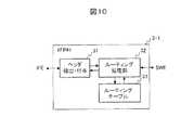
図7において,IFE2−1に入力されたパケット70は,データ部71とヘッダ部72より構成されている。IFE2−1内の入力側転送処理部23にて,レイヤ3処理が必要であると判定されると,パケットからはヘッダ部分72のみが取り出され,レイヤ3処理専用のxFP3−1へと送信される。また,データ部分71は待ちあわせバッファ235にてxFPからのヘッダの受信を待つ。ヘッダ部分74にはxFP3−1に向けた内部ヘッダ72Hが付与され,この情報をもとに,xFP3−1に到達する。レイヤ3処理向けxFP3Aの構成を図10に示す。xFP3−1に入力されたヘッダ72は,ヘッダ抽出・付与部31にて,ヘッダが取り出され,ルーティング処理部にて,宛先ポート検索,フィルタリング,QoSなどの処理が行われる。
図8は本発明のパケット通信装置の構成例を示すブロック図である。
図9は本発明のパケット通信装置の構成例を示すブロック図である。
図10本発明のパケット通信装置の機能拡張パケット処理部(xFP)の構成例を示すブロック図である。
各IPアドレスに対しての処理内容はルーティングテーブル33に格納されている。ルーティング処理部32により得られた情報を含むヘッダ74はヘッダ抽出・処理部31にて,図8に示すように,出力元のIFE2(本例ではIFE2−1)に返送されるように内部ヘッダ74Hが付与される。出力元のIFE2(本例ではIFE2−1)に到着したヘッダ74は図9に示すように,待合せバッファ235で待機しているデータ部71と組合せて,さらに,所望の出力IFEを示す装置内部ヘッダ70Hを付与した後,SWE1経由で出力IFE2(本例の場合,IFE2−n)へと転送される。なお,レイヤ3処理向けxFPは,IPプロトコルのバージョンの違いやプロトコルのエンハンス等により,新たなモジュールとして追加搭載することが可能である。
図11〜図14を用いて,次に,上位レイヤパケット転送の例を示す。
図11において,IFE2−1に入力されたパケット80は,データ部81とヘッダ部82より構成されている。IFE2−1内の入力側転送処理部23にて,上位レイヤ処理が必要であると判定されると,パケット80全体は,上位レイヤ処理専用のxFP3(本例ではxFP3−2)へと送信される。パケット80にはxFP3−2に向けた装置内部ヘッダ82Hが付与され,この情報をもとに,パケット80はxFP3−2に到達する。上位レイヤ処理向けxFP3−2の構成例を図14に示す。xFP3−2に入力されたパケット80は,バス変換部34にて,PCIバスなどの汎用バスにて,ネットワークプロセッサ(NP)37,もしくは,マイクロプロセッサユニット(MPU)36に転送され,所望の上位レイヤ処理が行われる。
図12に示すように,上位レイヤ処理後のパケットには,パケットヘッダ83および出力元のIFE2(本例ではIFE2−1)に返送されるように内部ヘッダ83Hが付与される。
図13に示すように,出力元のIFE2(本例ではIFE2−1)に到着したパケット80は,所望の出力IFEを示す装置内部ヘッダ80Hを付与した後,SWE1経由で所望の出力IFE2(本例の場合,IFE2−n)へと転送される。なお,上位レイヤ処理の一般的なものとしては,RTPやHTTPのヘッダ,URL,クッキー,SSLID,アプリケーション識別子,ファイル拡張子などにより転送先を判断するものがあげられる。これらは,機能の違いや,エンハンス等により,異なるxFPモジュールとして提供され,必要に応じて搭載される。
次に別の実施例として,ひとつの高機能モジュールの処理能力が不足してきた場合に,同一の高機能モジュールを追加搭載する場合など,性能に対するスケーラリティを実現する場合の例について説明する。
図15には,xFP3−1の処理能力を増強する場合に,xFP3−1と同種の機能拡張パケット処理部であるxFP3−4を追加搭載して,この2つのxFP間で負荷分散処理を行う例を示している。IFE2−1に入力したレイヤ3パケット90(データ部91およびパケットヘッダ部92より構成される)および,パケット100(データ部101およびパケットヘッダ部102より構成される)は,入力側転送処理部23にて,それぞれのヘッダ部分が取り出されて,パケットヘッダ92に対しては,xFP3−1宛ての装置内部ヘッダ92Hが,また,パケットヘッダ102に対しては,xFP3−4宛ての装置内部ヘッダ102Hが付与される。装置内部ヘッダに従い,パケットヘッダ92はxFP3−1にて処理され,パケットヘッダ102はxFP3−4にて負荷分散的に処理される。
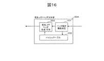
ここで,xFP間で負荷分散を実現する方法について3通りの方式を説明する。図16を用いて,まず,第1の方式を説明する。入力側転送処理部23内の宛先xFPヘッダ付与部233Aは,ヘッダ解析・機能判定部2331,ハッシュテーブル2332,および,宛先xFPヘッダ付与・生成部2333より構成される。宛先xFPヘッダ付与部233Aに入力されたIPパケットは,ヘッダ解析・機能判定部2331にて機能毎の判定が行われる。(本例では,レイヤ3処理に相当するxFP3−1,もしくは,xFP3−4での機能であることが判定される)。その後,ハッシュテーブル2332にて,送信IPアドレス(ソースIPアドレス:SID)もしくは,送信IPアドレスと宛先IPアドレス(DID)の組合せをベースとしたフロー情報をキーにしたハッシュ処理が行われ,対応するxFP(本例では,パケットヘッダ92はxFP3−1,パケットヘッダ102はxFP3−4)に振分けられる。ハッシュテーブル2332の演算結果に基づき,パケットヘッダ92に対しては,xFP3−1宛ての装置内部ヘッダ92Hが,また,パケットヘッダ102に対しては,xFP3−4宛ての装置内部ヘッダ102Hが宛先xFPヘッダ付与・生成部2333にて付与される。この方式では,同一のフローは同一のxFPにより処理されるため,負荷分散処理によるパケット順序の逆転は発生しないが,フローが偏った場合には,効率的な負荷分散が行えないという特徴を持つ。
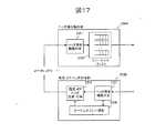
図17を用いて,次に,第2の負荷分散方式について説明する。入力側転送処理部23内の宛先xFPヘッダ付与部233Bは,ヘッダ解析・機能判定部2331,シーケンスナンバ発生部2334,および,宛先xFPヘッダ付与・生成部2333より構成される。また,ヘッダ抽出解析部234Bは,ヘッダ抽出機能判定部2351およびリシーケンスバッファ2352より構成される。宛先xFPヘッダ付与部233Bに入力されたIPパケットは,ヘッダ解析・機能判定部2331にて機能の判定が行われる。本例では,レイヤ3処理に相当するxFP3−1,もしくは,xFP3−4での機能であることが判定される。その後,シーケンスナンバ発生部2334にて,フロー毎のIPパケットに対してシーケンスナンバの生成が行われる。また,シーケンスナンバ発生部2334ではフロー毎のシーケンスナンバが管理されている。次に,宛先xFPヘッダ付与・生成部2333に入力されたパケットは,機能毎に,複数のxFP間で巡回的に振分けが行われる。(本例では,xFP3−1,もしくは,xFP3−4に対して巡回的に振分けが行われる。)この方式では,同一のフローは必ずしも同一のxFP3により処理されるとは限らないため,負荷分散処理によるパケット順序の逆転が発生する。そこで,xFP3により処理が施されたパケットは,ヘッダ抽出解析部234Bにおいて,パケット順序の再構成が行われる。具体的には,パケットは,ヘッダ解析機能判定部2351により該当する機能およびフロー単位が識別され,これらを元にリシーケンスバッファ2352に格納され,宛先xFPヘッダ付与部233Aで付与されたシーケンスナンバを元に順序制御が行われる。次に,第3の負荷分散方式について図18,図19を用いて説明する。
【0008】
図18は、本発明のパケット通信装置のインタフェースモジュールの別の構成例を示すブロック図である。
図19は、本発明のパケット通信装置の機能拡張パケット処理部(xFP)の別の構成例を示すブロック図である。
入力側転送処理部23内の宛先xFPヘッダ付与部233Cは,ヘッダ解析・機能判定部2331,宛先xFPヘッダ付与・生成部2333より構成される。また,ヘッダ抽出解析部234Cは,ヘッダ解析機能判定部2351,リシーケンスバッファ2352,および管理パケット抽出部2353より構成される。さらに,入力側転送処理部23は,xFP負荷状態管理部236を有する。宛先xFPヘッダ付与部233Cに入力されたIPパケットは,ヘッダ解析・機能判定部2331にて機能毎の判定が行われる。機能が判定されると,これをxFP負荷状態管理部236に通知する。xFP負荷状態管理部236では,各xFP毎の負荷状態を管理しており,該当機能についてのxFP3が複数搭載されている場合には,最も負荷の軽いxFP3を選択してこれを宛先xFPヘッダ付与・生成部2333に通知する。宛先xFPヘッダ付与・生成部2333においては,xFP負荷状態管理部236からの指示を受けたxFP3に該当する装置内ヘッダをパケットに付与する。この方式においても,同一のフローは必ずしも同一のxFP3により処理されるとは限らないため,負荷分散処理によるパケット順序の逆転が発生する。そこで,xFP3により処理が施されたパケットは,ヘッダ抽出解析部234Bにおいて,パケット順序の再構成が行われる。具体的には,パケットは,ヘッダ解析機能判定部2351により該当する機能およびフロー単位が識別され,これらを元にリシーケンスバッファ2352に格納され,宛先xFPヘッダ付与部233Cで付与されたシーケンスナンバを元に順序制御が行われる。
また,本方式では,図19に示すように各xFPにおいては,自身の負荷を観測し,定期的に負荷状態をIFE2に通知するための,負荷観測・管理パケット発生部38を有する構成とする。各IFEでは,xFPから管理パケットを定期的に受信すると,これを管理パケット抽出部2353にて抽出し,負荷情報をxFP負荷状態管理部236に通知する。
図20を用いて本発明の別の実施例を説明する。
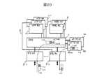
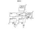
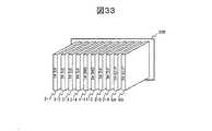
xFP3−2で説明した例のように,xFP3において上位レイヤの処理を行う場合には,パケット全体をxFP3を送受信する必要があるので,上位レイヤ処理を希望するパケットが多数装置に入力された場合には,論理バス5の帯域がネックとなり,上位レイヤ処理の効率が低下する可能性がある。そこで,図20に示すように,xFTR6(機能拡張パケット処理トランクモジュール)を追加する。xFTR6は,上位レイヤ処理専用のモジュールであり,IFE2と同一のSWE1のインタフェースを持つ。xFTR6はSWE1を介してIFE2に接続されるため,上位レイヤ処理のパケットが増えた場合の論理バス5の帯域ネックが解消できる。xFTR6は上位レイヤの機能毎に複数毎搭載可能である(図20では,xFTR6A,xFTR6Bの2毎のモジュールが搭載されている。)。もちろん,図30に示すようにxFPモジュールが搭載されず,xFTRモジュールのみを搭載する構成も可能である。また,前述の例で示したように,同機能のxFTRモジュールを複数毎搭載して,負荷分散を行うことにより,処理性能のスケーラビリティを実現することも可能である。負荷分散を行う場合に,IFE2に搭載される必要機能については,図16から図19と同様であるため説明を省略する。以下,IFE2,xFTRの実装例について説明する。図31は,バックプレーン200に対して,複数のIFE(2−1〜2−6)およびSWE(1−2,1−2)が搭載されており,スロット201およびスロット202は空きの状態となっている例を示している。この空きスロット201,202に対しては,図32に示すように新たなIFE(2−7,2−8)を搭載することも可能であり,また,図33に示すようにxFTR(6A,6B)を搭載することも可能である。
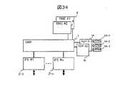
本発明の別の実施例について,図34,35を用いて説明する。この実施例では、高機能パケット処理部は、スロットに搭載され、自らもスロットを有する第1のモジュールと、第1のモジュールのスロットに接続される第2のモジュールから構成されている。
図34に示すように,xFP2の実装形態として,IFEスロットに対して接続アダプター(ADP7)を介して接続を行う。
図35はアダプター部の斜視図を示している。ADP7はSWE1から受信したパケットをヘッダに基づき複数のxFP(本例では,8A−1〜8A−3)に振分けを行い,また,複数のxFP(8A−1〜8A−3)から受信したパケットを多重してSWE1に送出する機能を有する。本実装形態を用いることで,xFP2専用のスロットおよび配線5を予め用意しておく必要がなくなり,また,xFTRを実装する場合のように,IFEのスロットが単一の高機能モジュールで専用されることなく,ひとつのIFEスロットに対して,複数のxFPを必要に応じて順次追加搭載することが可能となる。図21を用いて本発明のさらに別の実施例を説明する。
IFE2内の入出力転送処理部23内に入出力I/F選択回路237を設ける。論理バス5を経由してxFP3と送受信が行われるパケットヘッダおよびパケットには,装置内部ヘッダが付与されるが,この装置内部ヘッダ形式はSWE1に対して,送受信されるパケットに付与される装置内部ヘッダ形式と同形式とする。図22に示すように,論理バス5に障害が発生して,使用負荷になった場合,高機能処理を希望するパケットもしくはパケットヘッダは,入出力I/F選択回路237にて,パケットの送出先をxFPI/F26ではなく,パケットバッファ24を介してSWE25経由でxFP3にアクセスを行う。図22においては,図8におけるパケット70のパケットヘッダ72が論理バス5ではなくSWE1を使用してxFP3−1にアクセスする例を示している。また,xFP3においても,高機能処理後のパケットもしくはパケットヘッダは論理バス5を使用せずに,SWE1経由で送信元のIFE2に返送する。以上のように,論理バス5においてのデータ転送形式をSWE1においてのデータ転送形式と同一にしておくことで,論理バス5障害時には,SWE1経由を予備経路として使用することが可能となるため,論理バス5を二重化することなく,信頼性の高いシステムが,低コストで実現可能となる。
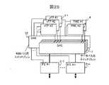
本発明のさらに別の実施例を図24,図25を用いて説明する。
前述の説明では,IFE2とxFP3との間の通信は,論理バス5で接続されているが,本接続機構はイーサネットなどのバス形式の他,図24に示すようにCPSW(Control Path Switch)51を用いる構成としても良い。CPSW51を用いることで,IFE2とxFP3のポイント・ポイント接続が可能となり通信帯域を有効に使用可能になる。
図25は本発明のパケット通信装置の構成例を示すブロック図である。図25に示すように,SWE1を複数枚使用してスイッチを構成する場合には,SWE1の一枚を制御パス用に割り当てて,制御パス用スイッチ面(SWE52)としても良い。この場合には,物理的に同一のSWE1を制御パス用にも使用できるという利点がある。
本発明のさらに別の実施例について,図26〜図29を用いて説明する。
前述の実施例では,高機能処理を必要とするパケットに関しての処理は,機能拡張パケット処理部であるxFP3において行われているが,本処理の同等機能を,スイッチ部の一部に統合することによっても機能拡張性をもつパケット通信装置を提供することが可能である。
図26で示すパケット通信装置においては,複数のSWE1に対して,複数のFSWE(Functonal Switch Elament)10が追加搭載可能な構成となっている。インタフェースエレメントにおいて,単純レイヤ2パケットと判定されたものは,バッファレスのSWE1に転送され,高機能処理を必要とするパケットは,FSWE10に転送される。この構成においては、機能拡張パケット処理部は、複数の回線インタフェース2-1と接続されるクロスバススイッチ10を有している。機能拡張パケット処理部の有するクロスバススイッチ10と通常のクロスバススイッチ1は、共通のスロットに接続可能である。回線インターフェイスからの接続経路は、機能拡張パケット処理部の有するクロスバススイッチ10と通常のクロスバススイッチ1で別個独立になっている。
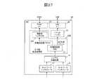
図27を用いて本構成のインタフェースエレメントIFE2Bの入力側機能ブロックについて説明する。IFE2Bの入力側は,ネットワークインタフェース21,レイヤ2中継処理部22,入力側転送処理部23,パケットバッファ24,SWEI/F25および,FSWEI/F27より構成される。装置に入力されたフレームは,まず,ネットワークインタフェース21にて,物理層処理が行われる。イーサネットの場合にはMAC(Media Access Control)層の処理が行われる。その後,レイヤ2中継処理部22にて,フレーム内にある宛先アドレス,送信元アドレス,VID(VLAN ID),FDB(Forwarding Data Base)などを利用して,判定作業が行われる。この判定作業により,宛先のMACアドレスの目的出力ポートを特定する。その後,入力側転送処理部23にて,入力フレーム(レイヤ3ではパケットと呼ばれる)に対して,高機能処理をするか否かの判定を行う。入力側転送処理部23は,高機能処理判定部231,機能別ヘッダ付与部238より構成される。まず,入力されたパケットは,パケットのヘッダを識別することにより高機能処理判定部231にて,高機能処理が必要か否かの判定が行われる。高機能処理が必要とされないパケット(フレーム)については,その後の処理をバイパスしてパケットバッファ24に送信される。パケットバッファ24に入力されるパケットは,キューイングされて,他のIFE2との間での出力競合制御を行った後に,SWEI/F25を通してSWE1へ出力される。高機能処理判定部231において,高機能処理が必要と判定されたパケットについては,機能に対応したFSWE10に送信されるように,宛先FSWE10行きのヘッダが付与され,その後,FSWEI/F27を通して,パケットバッファ24は通らずに,FSWE10に対して出力される。
以上のように、回線インターフェイスは、いずれのクロスバススイッチに入力パケットを振り分けるかを決定する振り分け機能を有する。また、回線インターフェイスはいずれのスイッチにも対応できるように,インターフェイスFSWE I/F, SWE I/Fを有している。
図28を用いて次にFSWE10の構成について説明する。FSWE10は,機能処理部であるFP11,入力パケットバッファ12および出力パケットバッファ13より構成される。IFE2から送信されたパケットは,入力パケットバッファ12に入力される。入力パケットバッファ12においては,入力されるパケットは,多重部120により,多重されてFIFOバッファ121にキューイングされる。FIFOバッファにキューイングされたパケットは読み出されて,FP11に入力される。FP11入力されたパケットは,ルーティング処理部110にて,ヘッダが取り出され,宛先ポート検索,フィルタリング,Qosなどの処理が行われる。各IPアドレスに対しての処理内容はルーティングテーブル111に格納されている。ルーティングテーブル111により得られた情報を元にして,宛先ポート情報を含む装置内部ヘッダをパケットに付与する。その後パケットは出力パケットバッファ13へ入力される。出力パケットバッファ13に入力されたパケットは,ルーティング処理部110で付与された装置内ヘッダの情報を元に,出力IFE2毎のFIFOバッファ131に格納された後,所望のIFE2に対して出力される。図28の例においては,レイヤ3パケットに対する処理を行う例を示したが,FSWE10は,図14で説明したような上位レイヤ処理の機能等を持つ拡張機能パケット処理モジュールとして提供される。
図29を用いて本構成のインタフェースエレメントIFE2Bの出力側機能ブロックについて説明する。IFE2Bの出力側の機能ブロックとしては,SWEI/F25,FSWEI/F26,パケットバッファ27,出力側転送処理部28,および,ネットワークインタフェース21より構成される。SWE1から転送されたパケットは,SWEI/F25を通してパケットバッファ27に入力される。FSWE10から転送されたパケットは,FSWEI/F26を通してパケットバッファ27に入力される。SWE1でのパケット転送形態がセル形式,つまり,固定長の複数パケット形式で行われる場合には,パケットバッファ27にて元の可変長パケットへの再構成が行われる。また,パケットバッファ27においては,品質クラス別の応じた優先出力制御が行われる場合もある。パケットバッファ27から出力されたパケット(レイヤ3パケットの場合)は,出力側転送処理部28にて,次に転送する宛先に向けてヘッダの書き換えが行われる。具体的には,宛先MACアドレスをネクストホップ(Next Hop)と呼ばれる,宛先までの次の経路にあるルータ(スイッチ)をMACアドレスに書き換える。その後,パケットはネットワークインタフェース21を通じて出力回線から次の宛先に向けて出力される。
図36により、最後に,前述のIFE2における高機能処理機能部分を選択搭載可能な構成について示す。本構成では,入力側転送処理部23を追加搭載可能なソケット部2301および2つのセレクタ2303A,2303Bを有する。入力側転送処理部23が搭載されない場合には,ソケット部2301をバイパスして結線2302を使用するようにセレクタ2303A,2303Bを切り替え,また,入力側転送処理部23が搭載される場合には,これを使用するようにセレクタ2303A,2303Bを切り替る。本構成により,L2単純転送のみ行うIFE2では,高機能処理部23を搭載する必要が無く,低コストでのIFEモジュール提供が可能になる。
このように,本実施例によれば,機能追加が柔軟に可能なパケット通信装置が提供できる。具体的には,レイヤ2の単純転送機能のみの提供によるパケット通信装置をベースモデルとし,上位レイヤ処理や,高機能サービスなどの機能が要求される場合には,必要に応じてこれらを,高機能パケット処理モジュールもしくは高機能スイッチモジュールとしてベースモデルに追加可能となるようなパケット通信装置が提供できる。
【0009】
【発明の効果】
以上説明した実施例によれば,次のような効果が期待できる。
(1)パケット通信装置を構成する場合に,レイヤ2の単純転送機能のみを有するパケット通信装置をベースモデルとし,上位レイヤ処理や,高機能サービスなどの機能を高機能モジュールとしてベースモデルに追加が可能であるような機能拡張性を有するパケット通信装置が提供できる。
(2)レイヤ2の単純転送機能のみを有するパケット通信装置をベースモデルとし,上位レイヤ処理や,高機能サービスなどの機能をベースモデルに高機能モジュールとして追加が可能であるような機能拡張性を有するパケット通信装置において,高機能モジュールへの通信パスの予備パスとしてスイッチ経由パスを使用することにより,低コストで信頼性の高いパケット通信装置を提供できる。
【図面の簡単な説明】
【図1】本発明のパケット通信装置の機能ブロックを示すブロック図である。
【図2】従来のパケット通信装置の構成を示すブロック図である。
【図3】従来のパケット通信装置の構成を示すブロック図である。
【図4】本発明のパケット通信装置のインタフェースモジュールの一構成を示すブロック図である。
【図5】本発明のパケット通信装置の構成例を示すブロック図である。
【図6】本発明のパケット通信装置の構成例を示すブロック図である。
【図7】本発明のパケット通信装置の構成例を示すブロック図である。
【図8】本発明のパケット通信装置の構成例を示すブロック図である。
【図9】本発明のパケット通信装置の構成例を示すブロック図である。
【図10】本発明のパケット通信装置の機能拡張パケット処理部(xFP)の構成例を示すブロック図である。
【図11】本発明のパケット通信装置の構成例を示すブロック図である。
【図12】本発明のパケット通信装置の構成例を示すブロック図である。
【図13】本発明のパケット通信装置の構成例を示すブロック図である。
【図14】本発明のパケット通信装置の機能拡張パケット処理部(xFP)の別の構成例を示すブロック図である。
【図15】本発明のパケット通信装置の構成例を示すブロック図である。
【図16】本発明のパケット通信装置のインタフェースモジュールの別の構成例を示すブロック図である。
【図17】本発明のパケット通信装置のインタフェースモジュールの別の構成例を示すブロック図である。
【図18】本発明のパケット通信装置のインタフェースモジュールの別の構成例を示すブロック図である。
【図19】本発明のパケット通信装置の機能拡張パケット処理部(xFP)の別の構成例を示すブロック図である。
【図20】本発明のパケット通信装置の構成例を示すブロック図である。
【図21】本発明のパケット通信装置のインタフェースモジュールの別の構成例を示すブロック図である。
【図22】本発明のパケット通信装置の構成例を示すブロック図である。
【図23】本発明のパケット通信装置のインタフェースモジュールの別の構成例を示すブロック図である。
【図24】本発明のパケット通信装置の構成例を示すブロック図である。
【図25】本発明のパケット通信装置の構成例を示すブロック図である。
【図26】本発明のパケット通信装置の構成例を示すブロック図である。
【図27】本発明のパケット通信装置のインタフェースモジュールの別の構成例を示すブロック図である。
【図28】本発明のパケット通信装置のスイッチモジュールの構成を示すブロック図である。
【図29】本発明のパケット通信装置のインタフェースモジュールの別の構成例を示すブロック図である。
【図30】本発明のパケット通信装置の構成例を示すブロック図である。
【図31】本発明のパケット通信装置の実装構成の例である。
【図32】本発明のパケット通信装置の実装構成の例である。
【図33】本発明のパケット通信装置の実装構成の例である。
【図34】本発明のパケット通信装置の構成例を示すブロック図である。
【図35】本発明のパケット通信装置の実装構成の例である。
【図36】本発明のパケット通信装置のインタフェースモジュールの別の構成例を示すブロック図である。
【符号の説明】
1・・・スイッチエレメント(SWE),2・・・インタフェースエレメント(IFE),3・・・機能拡張パケット処理部(xFP),4・・・ルーティングマネジャエレメント(RME),5・・・論理バス。[0001]
BACKGROUND OF THE INVENTION
The present invention relates to a packet data communication apparatus for performing routing / forwarding for
[0002]
[Prior art]
[Non-Patent Document 1]
Hitachi Review Vol. 49 (2000), No.4
[Non-Patent Document 2]
USP 6905725
[Patent Document 1]
JP 2002-64542
In recent years, data traffic including the Internet has been increasing rapidly. In addition, there is a movement to provide high-quality, high-reliability services on the Internet infrastructure, such as transaction processing conventionally performed using dedicated lines. In order to cope with this, not only the transmission path but also the capacity, speed and reliability of the packet data communication device are required. Further, in the future, in order to quickly respond to new routing protocols and new services, or to make it possible to easily add necessary functions, packet data communication devices are required to have functional flexibility. An example of a packet data communication apparatus that performs
[0003]
Another example of the hardware router configuration is disclosed in US Pat. No. 6,905,725 (Non-Patent Document 2).
FIG. 3 shows an outline of a hardware router disclosed in Non-Patent
Japanese Patent Application Laid-Open No. 2002-64542 (Patent Document 1) discloses a technique for performing determination processing of a labeled packet and an IP packet at an input line interface, and sending an IP header to a forwarding engine based on the determination result. However, the scalability of the process was not considered.
[0004]
[Problems to be solved by the invention]
Since the switch shown in Non-Patent
Therefore, an object of the present invention is to provide a packet communication apparatus in which functions can be added flexibly. More specifically, it is possible to provide a packet communication apparatus having a minimum subset configuration as a base model by using only the
[0005]
[Means for Solving the Problems]
The packet communication device includes a basic switch element, a basic packet transfer unit, a function expansion packet processing unit, and a routing manager. The basic packet transfer unit has a
More specifically, when only the header processing is required in the function extension packet processing unit, only the header is transferred to the function extension packet processing unit, and a plurality of packets constituting a series of flows are transmitted. For what is to be assembled and processed in the upper layer, it has a transfer control function for transferring the entire packet to the function expansion packet processing unit.
In a preferred aspect of the present invention, a plurality of line interfaces that receive an input packet, a routing manager that determines a transfer path of the input packet, a crossbar switch connected to the plurality of line interfaces via a first connection path, A high-function packet processing unit connected to the line interface of the second line via the second connection path, and a high-function processing determination unit for determining whether or not the input packet requires high-function processing, Based on the determination of the high function processing determination unit, at least a part of the input packet is transferred to the high function packet processing unit. Unlike the data path (first connection path), the second connection path that does not go through the cross bus switch is used for connection to the high-function module, thereby preventing interference with the main signal data. These connection paths can have a bus configuration or a one-to-one connection.
Furthermore, the second connection path can be made redundant by the first connection path. At this time, the format of the header or packet transferred from the basic packet transfer unit to the function expansion packet processing unit may be the same as the format of the packet transferred from the basic packet transfer unit to the basic switch element. Transfer path switching to transfer the header or packet to the function expansion packet processing unit via the switch element when a failure occurs in the path transferred from the basic packet transfer unit to the function expansion packet processing unit It has a function. In addition, when the processing capability of the function expansion packet processing unit is insufficient, the same type of function expansion packet processing unit is additionally installed, and the basic packet transfer unit has a function for distributing the load. In the basic packet transfer unit, in order to perform load distribution, (1) HASH function distribution function based on destination IP address, (2) cyclic selection distribution function and order reversal prevention function, or (3) each function expansion packet processing unit It has one of load balancing function and order reverse prevention function based on load observation.
[0006]
Another configuration of the packet communication apparatus includes a basic switch element, a basic packet transfer unit, a function expansion switch element, and a routing manager. The function expansion switch element performs higher layer processing of
In another aspect of the present invention, a plurality of line interfaces, a crossbar switch connected to the plurality of line interfaces, and a plurality of slots for connecting high-functional units connected to the plurality of line interfaces are provided. Each line interface of the plurality of line interfaces has a
[0007]
DETAILED DESCRIPTION OF THE INVENTION
An embodiment of a packet communication device according to the present invention will be described.
FIG. 1 shows the overall configuration of the packet communication apparatus of the present invention. The packet communication apparatus includes a plurality of interface elements (IFE) 2, a function expansion packet processing unit (xFP) 3 that performs various high-function processes, a plurality of
First, the functional blocks of IFE2 will be described with reference to FIG. The input side of the
Thereafter, the input-side
Next, an example of
FIG. 6 is a block diagram showing a configuration example of another packet communication apparatus of the present invention. When high-function processing is not required at all depending on the application destination of the apparatus, and only a
A functional block on the output side of the
Next, an example of
In FIG. 7, a
FIG. 8 is a block diagram showing a configuration example of the packet communication apparatus of the present invention.
FIG. 9 is a block diagram showing a configuration example of the packet communication apparatus of the present invention.
10 is a block diagram showing a configuration example of a function expansion packet processing unit (xFP) of the packet communication apparatus of the present invention.
The processing contents for each IP address are stored in the routing table 33. As shown in FIG. 8, the
Next, an example of upper layer packet transfer will be described with reference to FIGS.
In FIG. 11, a
As shown in FIG. 12, an internal header 83H is added to the packet after the upper layer processing so as to be returned to the
As shown in FIG. 13, a
Next, as another embodiment, an example will be described in which performance scalability is realized, such as when the same high-function module is additionally installed when the processing capability of one high-function module is insufficient.
In FIG. 15, when enhancing the processing capacity of xFP3-1, xFP3-4, which is a function expansion packet processing unit of the same type as xFP3-1, is additionally installed, and load distribution processing is performed between the two xFPs. An example is shown. The
Here, three methods for realizing load distribution between xFPs will be described. First, the first method will be described with reference to FIG. The destination xFP
Next, the second load distribution method will be described with reference to FIG. The destination xFP
[0008]
FIG. 18 is a block diagram showing another configuration example of the interface module of the packet communication apparatus of the present invention.
FIG. 19 is a block diagram showing another configuration example of the function expansion packet processing unit (xFP) of the packet communication apparatus of the present invention.
The destination xFP header adding unit 233C in the input side
Further, in this method, as shown in FIG. 19, each xFP has a load observation / management
Another embodiment of the present invention will be described with reference to FIG.
When the upper layer processing is performed in xFP3 as in the example described in xFP3-2, since it is necessary to transmit / receive the entire packet to / from xFP3, when a packet for which upper layer processing is desired is input to a large number of devices In some cases, the bandwidth of the
Another embodiment of the present invention will be described with reference to FIGS. In this embodiment, the high-function packet processing unit includes a first module that is mounted in a slot and has a slot itself, and a second module that is connected to the slot of the first module.
As shown in FIG. 34, as an implementation form of xFP2, connection is made to an IFE slot via a connection adapter (ADP7).
FIG. 35 shows a perspective view of the adapter portion. The
An input / output I /
Still another embodiment of the present invention will be described with reference to FIGS.
In the above description, the communication between the
FIG. 25 is a block diagram showing a configuration example of the packet communication apparatus of the present invention. As shown in FIG. 25, when a switch is configured by using a plurality of SWE1, one SWE1 may be assigned for the control path and used as the control path switch surface (SWE52). In this case, there is an advantage that the physically same SWE1 can be used for the control path.
Still another embodiment of the present invention will be described with reference to FIGS.
In the above-described embodiment, processing relating to a packet that requires high-function processing is performed in xFP3, which is a function expansion packet processing unit, but the equivalent function of this processing is integrated into a part of the switch unit. Thus, it is possible to provide a packet communication device having function expandability.
In the packet communication apparatus shown in FIG. 26, a plurality of FSWEs (Functional Switch Elements) 10 can be additionally mounted on a plurality of SWE1s. In the interface element, a packet determined as a
The input side functional block of the interface element IFE2B having this configuration will be described with reference to FIG. The input side of the IFE 2B includes a
As described above, the line interface has a distribution function for determining which cross-bus switch the input packet is distributed to. Further, the line interface has interfaces FSWE I / F and SWE I / F so as to be compatible with any switch.
Next, the configuration of the
The output side functional block of the interface element IFE2B having this configuration will be described with reference to FIG. The function block on the output side of the IFE 2B is composed of a SWEI /
FIG. 36 finally shows a configuration in which the high-function processing function part in the
Thus, according to the present embodiment, a packet communication apparatus capable of flexibly adding functions can be provided. Specifically, the base model is a packet communication device that provides only the
[0009]
【The invention's effect】
According to the embodiment described above, the following effects can be expected.
(1) When configuring a packet communication device, a packet communication device having only a
(2) A packet communication device having only a
[Brief description of the drawings]
FIG. 1 is a block diagram showing functional blocks of a packet communication apparatus of the present invention.
FIG. 2 is a block diagram showing a configuration of a conventional packet communication device.
FIG. 3 is a block diagram showing a configuration of a conventional packet communication device.
FIG. 4 is a block diagram showing a configuration of an interface module of the packet communication apparatus according to the present invention.
FIG. 5 is a block diagram showing a configuration example of a packet communication apparatus according to the present invention.
FIG. 6 is a block diagram illustrating a configuration example of a packet communication apparatus according to the present invention.
FIG. 7 is a block diagram showing a configuration example of a packet communication apparatus according to the present invention.
FIG. 8 is a block diagram showing a configuration example of a packet communication apparatus according to the present invention.
FIG. 9 is a block diagram illustrating a configuration example of a packet communication apparatus according to the present invention.
FIG. 10 is a block diagram showing a configuration example of a function expansion packet processing unit (xFP) of the packet communication apparatus of the present invention.
FIG. 11 is a block diagram illustrating a configuration example of a packet communication apparatus according to the present invention.
FIG. 12 is a block diagram illustrating a configuration example of a packet communication device according to the present invention.
FIG. 13 is a block diagram illustrating a configuration example of a packet communication apparatus according to the present invention.
FIG. 14 is a block diagram showing another configuration example of the function expansion packet processing unit (xFP) of the packet communication apparatus of the present invention.
FIG. 15 is a block diagram illustrating a configuration example of a packet communication apparatus according to the present invention.
FIG. 16 is a block diagram showing another configuration example of the interface module of the packet communication apparatus according to the present invention.
FIG. 17 is a block diagram showing another configuration example of the interface module of the packet communication apparatus according to the present invention.
FIG. 18 is a block diagram showing another configuration example of the interface module of the packet communication apparatus of the present invention.
FIG. 19 is a block diagram showing another configuration example of the function expansion packet processing unit (xFP) of the packet communication apparatus of the present invention.
FIG. 20 is a block diagram illustrating a configuration example of a packet communication apparatus according to the present invention.
FIG. 21 is a block diagram showing another configuration example of the interface module of the packet communication apparatus according to the present invention.
FIG. 22 is a block diagram illustrating a configuration example of a packet communication device according to the present invention.
FIG. 23 is a block diagram showing another configuration example of the interface module of the packet communication apparatus according to the present invention.
FIG. 24 is a block diagram illustrating a configuration example of a packet communication device according to the present invention.
FIG. 25 is a block diagram illustrating a configuration example of a packet communication apparatus according to the present invention.
FIG. 26 is a block diagram illustrating a configuration example of a packet communication apparatus according to the present invention.
FIG. 27 is a block diagram showing another configuration example of the interface module of the packet communication apparatus of the present invention.
FIG. 28 is a block diagram showing a configuration of a switch module of the packet communication apparatus of the present invention.
FIG. 29 is a block diagram showing another configuration example of the interface module of the packet communication apparatus of the present invention.
FIG. 30 is a block diagram illustrating a configuration example of a packet communication device according to the present invention.
FIG. 31 is an example of a mounting configuration of a packet communication apparatus according to the present invention.
FIG. 32 is an example of a mounting configuration of the packet communication apparatus of the present invention.
FIG. 33 is an example of a mounting configuration of a packet communication apparatus according to the present invention.
FIG. 34 is a block diagram showing a configuration example of a packet communication apparatus according to the present invention.
FIG. 35 is an example of a mounting configuration of a packet communication apparatus according to the present invention.
FIG. 36 is a block diagram showing another configuration example of the interface module of the packet communication apparatus according to the present invention.
[Explanation of symbols]
DESCRIPTION OF
Claims (18)
Translated fromJapanese入力パケットの転送経路を決定するルーティングマネジャーと、
上記複数の回線インタフェース部と第1の接続経路を介して接続されるクロスバスイッチと、
上記複数の回線インタフェース部と第2の接続経路を介して接続されるパケット処理部と、
上記入力パケットが上記パケット処理部での処理を必要とするか否かを決定するための、パケット処理判定部を有し、
上記パケット処理判定部にて、上記パケット処理部での処理が必要でないと判定されたパケットは、直接、前記クロスバスイッチに転送され、上記パケット処理部での処理が必要と判定された前記入力パケットは、上記パケット処理部に転送されて処理が行われ、再び,もとの回線インタフェース部に返送された後、前記クロスバスイッチに転送されることを特徴とする通信装置。A plurality of line interface units for receiving input packets;
A routing manager that determines the forwarding path of input packets;
A crossbar switch connected to the plurality of line interface units via a first connection path;
A packet processing unit connected to the plurality of line interface units via a second connection path;
A packet processing determination unit for determining whether or not the input packet requires processing in the packet processing unit;
The packet determined by the packet processing determination unit as not requiring processing by the packet processing unit is directly transferred to the crossbar switch, and the input packet determined to be processed by the packet processing unit Is transferred to the packet processing unit, processed, returned to the original line interface unit, and then transferred to the crossbar switch.
上記パケット処理部はレイヤ3以上の処理機能を有する請求項1または2に記載の通信装置。Each line interface unit of the plurality of line interface units has a layer 2 processing function,
The communication apparatus accordingto claim 1, wherein the packet processing unit has a processing function of layer 3 or higher.
上記第2の接続経路の障害時には、上記第1の接続経路により上記クロスバススイッチを経由して上記回線インタフェース部と上記パケット処理部のデータ送受信を行い、
上記回線インタフェース部は、上記第1及び第2の接続経路のどちらかに対して、データを送受信するかを選択する選択回路を有する請求項1から4のうちのいずれかに記載の通信装置。The data format of the first connection route and the second connection route is the same,
At the time of failure of the second connection path, data transmission / reception between the line interface unit and the packet processing unit is performed via the cross bus switch by the first connection path,
The line interface unit, said for either of the first and second connection path, the communication apparatus according to any one of claims 1 having a selection circuit for selecting whether to receive the data4.
上記第2のクロスバススイッチと上記クロスバススイッチは、共通のスロットに接続可能であり、
上記回線インタフェース部は、上記第2のクロスバススイッチと上記クロスバススイッチのいずれかに上記入力パケットを振り分ける振り分け機能を有する請求項1から7のうちいずれかに記載の通信装置。The packet processing unit includes a second cross bus switch connected to the plurality of line interface units via the second connection path,
The second cross bus switch and the cross bus switch can be connected to a common slot,
The line interface unit, the communication apparatus according to any one of the second cross-bus switch and claims 1 to7 having a sorting function for distributing said input packets to one of the cross-bus switch.
と、該第1のモジュールのスロットに接続される第2のモジュールを有する請求項9記載の通信装置。The communication apparatus according to claim9 , wherein the packet processing unit includes a first module connected to the slot and having a slot itself, and a second module connected to the slot of the first module.
上記複数の回線インタフェース部と接続されるクロスバスイッチと、
上記複数の回線インタフェース部と接続されるパケット処理ユニットを接続するための複数のスロットと、を有し
上記複数の回線インタフェース部の各回線インタフェース部は,レイヤ2処理機能および,入力パケットが上記パケット処理ユニットにおける処理を必要とするか否かを決定するための,パケット処理判定機能を有し,
上記パケット処理判定機能にて,上記パケット処理部での処理が必要でないと判定されたパケットは,直接,前記クロスバスイッチに転送され,上記パケット処理部での処理が必要と判定された前記入力パケットは,該当機能に対応する上記パケット処理ユニットに転送されてレイヤ3以上の処理が行われ,再び,もとの回線インタフェース部に返送された後で,前記クロスバスイッチに転送されることを特徴とする,パケット通信装置。A plurality of line interface units;
A crossbar switch connected to the plurality of line interface units;
A plurality of slots for connecting packet processing units connected to the plurality of line interface units; each line interface unit of the plurality of line interface units includes a layer 2 processing function; It has a packet processing judgment function to decide whether or not processing in the processing unit is required,
The packet determined by the packet processing determination function as not requiring processing by the packet processing unit is directly transferred to the crossbar switch, and the input packet determined to be processed by the packet processing unit. Is transferred to the packet processing unit corresponding to the corresponding function, layer 3 or higher processing is performed, returned to the original line interface unit, and then transferred to the crossbar switch. A packet communication device.
上記入力パケットの、送信元IPアドレスと宛先IPアドレスのうちいずれか一つを少なくとも含むフロー情報をキーにしたハッシュ処理を行うための、ハッシュテーブルと、上記判定の結果および上記ハッシュ処理の結果に基づいて、入力パケットを所定の上記パケット処理ユニットに振分ける宛先ヘッダ生成・付与部と、を有する請求項13記載のパケット通信装置。The load distribution unit includes a header analysis / function determination unit that determines a type of processing required for the input packet;
A hash table for performing hash processing using the flow information including at least one of the source IP address and the destination IP address of the input packet as a key, the determination result, and the hash processing result. The packet communication apparatus according to claim13 , further comprising: a destination header generation / assignment unit that distributes an input packet to the predetermined packet processing unit based on the input packet.
フロー毎のシーケンスナンバを管理するとともに、フロー毎のIPパケットに対してシーケンスナンバの生成を行うシーケンスナンバ発生部と、
入力パケットを、機能毎に、上記複数のパケット処理ユニット間に巡回的に振分けを行うための宛先ヘッダ付与・生成部とを有し、
さらに、上記パケット通信装置は、上記パケット処理ユニットにより処理が施された入力パケットの、パケット順序の再構成を行うヘッダ抽出解析を有する請求項13記載のパケット通信装置。The load distribution unit includes a header analysis / function determination unit that determines a type of processing required for the input packet;
A sequence number generator for managing the sequence number for each flow and generating a sequence number for the IP packet for each flow;
A destination header adding / generating unit for cyclically distributing the input packet for each function among the plurality of packet processing units,
14. The packet communication device according to claim13, further comprising: a header extraction analysis for reconfiguring the packet order of the input packet processed by the packet processing unit.
上記各パケット処理ユニット毎の負荷状態を管理し、上記ヘッダ解析・機能判定部から上記入力パケットの必要とする処理の通知を受け、当該処理を行うパケット処理ユニットが複数搭載されている場合には、最も負荷の軽い、あるいは、所定値よりも負荷の軽いパケット処理ユニットを選択する負荷状態管理部と、
上記負荷状態管理部で選択されたパケット処理ユニットに該当する装置内ヘッダをパケットに付与する宛先ヘッダ付与・生成部と、を有する請求項13記載のパケット通信装置。The load distribution unit includes a header analysis / function determination unit that determines a type of processing required for the input packet;
When the load status of each packet processing unit is managed, the notification of the processing required for the input packet is received from the header analysis / function determination unit, and a plurality of packet processing units for performing the processing are installed. A load state management unit that selects a packet processing unit having the lightest load or a lighter load than a predetermined value;
The packet communication device according to claim13 , further comprising: a destination header adding / generating unit that adds an in-device header corresponding to the packet processing unit selected by the load state management unit to the packet.
複数の回線インタフェース部と,上記複数の回線インタフェース部と接続されるクロスバスイッチと,上記複数の回線インタフェース部と接続される複数のパケット処理部とを有し,
上記複数の回線インタフェース部の各回線インタフェース部は,レイヤ2処理機能および,入力パケットが上記パケット処理部での処理を必要とするか否かを決定するための,パケット処理判定機能を有し,
上記パケット処理判定機能にて,上記パケット処理部での処理が必要でないと判定されたパケットは,直接,前記クロスバスイッチに転送され,上記パケット処理部での処理が必要と判定された前記入力パケットは,該当機能に対応するパケット処理部のいずれかに転送されてレイヤ3以上の処理が行われ,再び,もとの回線インタフェース部に返送された後で,前記クロスバスイッチに転送されることを特徴とする,パケット通信装置。A packet communication device,
A plurality of line interface units, a crossbar switch connected to the plurality of line interface units, and a plurality of packet processing units connected to the plurality of line interface units,
Each line interface unit of the plurality of line interface units has a layer 2 processing function and a packet processing determination function for determining whether an input packet requires processing in the packet processing unit,
The packet determined by the packet processing determination function as not requiring processing by the packet processing unit is directly transferred to the crossbar switch, and the input packet determined to be processed by the packet processing unit. Is transferred to one of the packet processing units corresponding to the corresponding function, processed at layer 3 or higher, returned to the original line interface unit, and then transferred to the crossbar switch. A packet communication device.
複数の回線インタフェース部と,上記複数の回線インタフェース部と接続されるクロスバスイッチと,上記複数の回線インタフェース部と接続される複数のパケット処理部とを有し,
上記複数の回線インタフェース部の各回線インタフェース部は,レイヤ2処理機能および,入力パケットが上記パケット処理部での処理を必要とするか否かを決定するパケット処理判定機能およびパケット待機バッファを有し,
上記パケット処理判定機能にて,上記パケット処理部での処理が必要でないと判定されたパケットは,直接,前記クロスバスイッチに転送され,上記パケット処理部での処理が必要と判定された前記入力パケットのパケットヘッダは,前記複数のパケット処理部のいずれかに転送され,上記パケット処理部での処理が必要と判定された前記入力パケットのパケットデータは,前記パケット待機バッファに格納され,前記パケット処理部によりレイヤ3以上の処理が終了した前記パケットヘッダは,もとの回線インタフェース部に返送された後,前記パケット待機バッファに格納されているパケットデータと併せて,前記クロスバスイッチに転送されることを特徴とする,パケットスイッチ。A packet switch,
A plurality of line interface units, a crossbar switch connected to the plurality of line interface units, and a plurality of packet processing units connected to the plurality of line interface units,
Each line interface unit of the plurality of line interface units has a layer 2 processing function, a packet processing determination function for determining whether or not an input packet requires processing in the packet processing unit, and a packet standby buffer. ,
The packet determined by the packet processing determination function as not requiring processing by the packet processing unit is directly transferred to the crossbar switch, and the input packet determined to be processed by the packet processing unit. Is transferred to one of the plurality of packet processing units, and the packet data of the input packet determined to be processed by the packet processing unit is stored in the packet waiting buffer, and the packet processing The packet header whose layer 3 or higher processing is completed is sent back to the original line interface unit and then transferred to the crossbar switch together with the packet data stored in the packet standby buffer. A packet switch characterized by
Priority Applications (3)
| Application Number | Priority Date | Filing Date | Title |
|---|---|---|---|
| JP2002298227AJP4023281B2 (en) | 2002-10-11 | 2002-10-11 | Packet communication apparatus and packet switch |
| US10/339,340US7298752B2 (en) | 2002-10-11 | 2003-01-10 | Packet communication device |
| CNB031555918ACN100488160C (en) | 2002-10-11 | 2003-08-29 | Packet communication device |
Applications Claiming Priority (1)
| Application Number | Priority Date | Filing Date | Title |
|---|---|---|---|
| JP2002298227AJP4023281B2 (en) | 2002-10-11 | 2002-10-11 | Packet communication apparatus and packet switch |
Publications (3)
| Publication Number | Publication Date |
|---|---|
| JP2004135106A JP2004135106A (en) | 2004-04-30 |
| JP2004135106A5 JP2004135106A5 (en) | 2005-11-10 |
| JP4023281B2true JP4023281B2 (en) | 2007-12-19 |
Family
ID=32064209
Family Applications (1)
| Application Number | Title | Priority Date | Filing Date |
|---|---|---|---|
| JP2002298227AExpired - Fee RelatedJP4023281B2 (en) | 2002-10-11 | 2002-10-11 | Packet communication apparatus and packet switch |
Country Status (3)
| Country | Link |
|---|---|
| US (1) | US7298752B2 (en) |
| JP (1) | JP4023281B2 (en) |
| CN (1) | CN100488160C (en) |
Cited By (1)
| Publication number | Priority date | Publication date | Assignee | Title |
|---|---|---|---|---|
| US8089718B2 (en) | 2006-01-10 | 2012-01-03 | Hitachi Global Technologies, Netherlands B.V. | Method and apparatus for increasing storage capacity of a hard disk drive |
Families Citing this family (68)
| Publication number | Priority date | Publication date | Assignee | Title |
|---|---|---|---|---|
| US7273601B2 (en)* | 2000-07-18 | 2007-09-25 | The University Of Western Ontario | Preparation of radiolabelled haloaromatics via polymer-bound intermediates |
| US7596139B2 (en) | 2000-11-17 | 2009-09-29 | Foundry Networks, Inc. | Backplane interface adapter with error control and redundant fabric |
| US20120155466A1 (en) | 2002-05-06 | 2012-06-21 | Ian Edward Davis | Method and apparatus for efficiently processing data packets in a computer network |
| US7187687B1 (en) | 2002-05-06 | 2007-03-06 | Foundry Networks, Inc. | Pipeline method and system for switching packets |
| US7809275B2 (en) | 2002-06-25 | 2010-10-05 | Finisar Corporation | XFP transceiver with 8.5G CDR bypass |
| US7437079B1 (en) | 2002-06-25 | 2008-10-14 | Finisar Corporation | Automatic selection of data rate for optoelectronic devices |
| US7664401B2 (en) | 2002-06-25 | 2010-02-16 | Finisar Corporation | Apparatus, system and methods for modifying operating characteristics of optoelectronic devices |
| US7486894B2 (en) | 2002-06-25 | 2009-02-03 | Finisar Corporation | Transceiver module and integrated circuit with dual eye openers |
| JP4108390B2 (en)* | 2002-07-08 | 2008-06-25 | 松下電器産業株式会社 | Wireless communication method, wireless communication terminal, and wireless LAN system |
| US6901072B1 (en) | 2003-05-15 | 2005-05-31 | Foundry Networks, Inc. | System and method for high speed packet transmission implementing dual transmit and receive pipelines |
| WO2005050925A1 (en)* | 2003-11-21 | 2005-06-02 | Canon Kabushiki Kaisha | A MODULAR APPROACH TO THE TCP/IPv6 HARDWARE IMPLEMENTATION |
| JP4365672B2 (en)* | 2003-12-04 | 2009-11-18 | 株式会社日立製作所 | Packet communication node equipment |
| US7817659B2 (en) | 2004-03-26 | 2010-10-19 | Foundry Networks, Llc | Method and apparatus for aggregating input data streams |
| US8730961B1 (en) | 2004-04-26 | 2014-05-20 | Foundry Networks, Llc | System and method for optimizing router lookup |
| JP4332079B2 (en) | 2004-07-01 | 2009-09-16 | 株式会社日立製作所 | Module type packet communication node equipment |
| JP4704729B2 (en) | 2004-10-20 | 2011-06-22 | 株式会社日立製作所 | Packet data processing node equipment |
| JP4369351B2 (en) | 2004-11-30 | 2009-11-18 | 株式会社日立製作所 | Packet transfer device |
| US20060120361A1 (en)* | 2004-12-03 | 2006-06-08 | Utstarcom, Inc. | Method and system for providing packet data services |
| JP2006229830A (en)* | 2005-02-21 | 2006-08-31 | Hitachi Ltd | Packet communication device |
| JP4309359B2 (en) | 2005-03-09 | 2009-08-05 | 株式会社日立製作所 | Packet communication apparatus and function expansion method thereof |
| US20060206706A1 (en)* | 2005-03-14 | 2006-09-14 | Bryan Dietz | Method and apparatus for dynamically distributing data flow in a communication network |
| US20060248374A1 (en)* | 2005-04-18 | 2006-11-02 | Macadam A D S | Packet Processing Switch and Methods of Operation Thereof |
| US8432809B2 (en)* | 2005-04-27 | 2013-04-30 | Broadcom Corporation | Method for communication between processors |
| US8040899B2 (en)* | 2005-05-26 | 2011-10-18 | Genband Us Llc | Methods, systems, and computer program products for implementing automatic protection switching for media packets transmitted over an ethernet switching fabric |
| JP4532352B2 (en)* | 2005-06-10 | 2010-08-25 | 株式会社ネクストマジック | Communication device |
| JP4585944B2 (en)* | 2005-08-31 | 2010-11-24 | 株式会社日立製作所 | Packet communication device |
| US7911940B2 (en) | 2005-09-30 | 2011-03-22 | Genband Us Llc | Adaptive redundancy protection scheme |
| US8448162B2 (en) | 2005-12-28 | 2013-05-21 | Foundry Networks, Llc | Hitless software upgrades |
| JP4609331B2 (en)* | 2006-01-27 | 2011-01-12 | 株式会社日立製作所 | Complex information platform apparatus and communication bandwidth guarantee method thereof |
| US7881188B2 (en) | 2006-02-03 | 2011-02-01 | Genband Us Llc | Methods, systems, and computer program products for implementing link redundancy in a media gateway |
| JP4626544B2 (en)* | 2006-03-13 | 2011-02-09 | 株式会社日立製作所 | Complex information platform device and management method of complex information platform device |
| US7429870B2 (en)* | 2006-06-21 | 2008-09-30 | Element Cxi, Llc | Resilient integrated circuit architecture |
| WO2007149527A2 (en)* | 2006-06-21 | 2007-12-27 | Element Cxi, Llc | Fault tolerant integrated circuit architecture |
| US7427871B2 (en)* | 2006-06-21 | 2008-09-23 | Element Cxi, Llc | Fault tolerant integrated circuit architecture |
| JP4815284B2 (en) | 2006-07-06 | 2011-11-16 | アラクサラネットワークス株式会社 | Packet transfer device |
| JP4758302B2 (en)* | 2006-08-30 | 2011-08-24 | アラクサラネットワークス株式会社 | Network node |
| US8238255B2 (en) | 2006-11-22 | 2012-08-07 | Foundry Networks, Llc | Recovering from failures without impact on data traffic in a shared bus architecture |
| US8155011B2 (en) | 2007-01-11 | 2012-04-10 | Foundry Networks, Llc | Techniques for using dual memory structures for processing failure detection protocol packets |
| US8225323B2 (en) | 2007-06-25 | 2012-07-17 | Alaxala Networks Corporation | Control device and control method for reduced power consumption in network device |
| US8509236B2 (en) | 2007-09-26 | 2013-08-13 | Foundry Networks, Llc | Techniques for selecting paths and/or trunk ports for forwarding traffic flows |
| JP5156332B2 (en)* | 2007-10-30 | 2013-03-06 | アラクサラネットワークス株式会社 | Packet transfer device |
| JP4901777B2 (en)* | 2008-02-05 | 2012-03-21 | アラクサラネットワークス株式会社 | Network relay device and network relay method |
| JP5111236B2 (en)* | 2008-05-22 | 2013-01-09 | 株式会社日立製作所 | Data transfer system |
| JP2010177752A (en)* | 2009-01-27 | 2010-08-12 | Hitachi Ltd | Network communication node |
| US9565207B1 (en) | 2009-09-04 | 2017-02-07 | Amazon Technologies, Inc. | Firmware updates from an external channel |
| US8887144B1 (en) | 2009-09-04 | 2014-11-11 | Amazon Technologies, Inc. | Firmware updates during limited time period |
| US10177934B1 (en) | 2009-09-04 | 2019-01-08 | Amazon Technologies, Inc. | Firmware updates inaccessible to guests |
| US8214653B1 (en) | 2009-09-04 | 2012-07-03 | Amazon Technologies, Inc. | Secured firmware updates |
| US8971538B1 (en) | 2009-09-08 | 2015-03-03 | Amazon Technologies, Inc. | Firmware validation from an external channel |
| US8102881B1 (en) | 2009-09-08 | 2012-01-24 | Amazon Technologies, Inc. | Streamlined guest networking in a virtualized environment |
| US8601170B1 (en) | 2009-09-08 | 2013-12-03 | Amazon Technologies, Inc. | Managing firmware update attempts |
| US8959611B1 (en)* | 2009-09-09 | 2015-02-17 | Amazon Technologies, Inc. | Secure packet management for bare metal access |
| US8640220B1 (en)* | 2009-09-09 | 2014-01-28 | Amazon Technologies, Inc. | Co-operative secure packet management |
| US8300641B1 (en) | 2009-09-09 | 2012-10-30 | Amazon Technologies, Inc. | Leveraging physical network interface functionality for packet processing |
| US8381264B1 (en) | 2009-09-10 | 2013-02-19 | Amazon Technologies, Inc. | Managing hardware reboot and reset in shared environments |
| US8599850B2 (en) | 2009-09-21 | 2013-12-03 | Brocade Communications Systems, Inc. | Provisioning single or multistage networks using ethernet service instances (ESIs) |
| EP2337274B1 (en)* | 2009-12-17 | 2014-03-05 | Alcatel Lucent | Method for processing a plurality of data and switching device for switching communication packets |
| US8472311B2 (en) | 2010-02-04 | 2013-06-25 | Genband Us Llc | Systems, methods, and computer readable media for providing instantaneous failover of packet processing elements in a network |
| JP5637749B2 (en)* | 2010-06-30 | 2014-12-10 | アラクサラネットワークス株式会社 | Packet relay device |
| US8391174B2 (en)* | 2010-07-13 | 2013-03-05 | Hewlett-Packard Development Company, L.P. | Data packet routing |
| WO2012093335A1 (en)* | 2011-01-06 | 2012-07-12 | Marvell Israel (M.I.S.L) Ltd. | Network device with a programmable core |
| CN102239669B (en)* | 2011-01-14 | 2015-01-21 | 华为技术有限公司 | Data forwarding method and router |
| US9729431B1 (en) | 2011-08-16 | 2017-08-08 | Marvell International Ltd. | Using standard fields to carry meta-information |
| US20130308496A1 (en)* | 2012-05-21 | 2013-11-21 | Broadcom Corporation | System and Method for Generic Multi-Domain Network Pruning |
| US10394751B2 (en)* | 2013-11-06 | 2019-08-27 | Solarflare Communications, Inc. | Programmed input/output mode |
| WO2016051813A1 (en)* | 2014-09-30 | 2016-04-07 | アラクサラネットワークス株式会社 | Relay apparatus |
| JP6489954B2 (en)* | 2015-06-19 | 2019-03-27 | ルネサスエレクトロニクス株式会社 | Semiconductor device and control method thereof |
| US20220400079A1 (en)* | 2019-11-13 | 2022-12-15 | Nippon Telegraph And Telephone Corporation | Sort device, sort method, and sort program |
Family Cites Families (20)
| Publication number | Priority date | Publication date | Assignee | Title |
|---|---|---|---|---|
| US5734649A (en)* | 1996-05-31 | 1998-03-31 | Bbn Corporation | Data packet router |
| US5864535A (en)* | 1996-09-18 | 1999-01-26 | International Business Machines Corporation | Network server having dynamic load balancing of messages in both inbound and outbound directions |
| US5905725A (en) | 1996-12-16 | 1999-05-18 | Juniper Networks | High speed switching device |
| US5918074A (en)* | 1997-07-25 | 1999-06-29 | Neonet Llc | System architecture for and method of dual path data processing and management of packets and/or cells and the like |
| US5974467A (en)* | 1997-08-29 | 1999-10-26 | Extreme Networks | Protocol for communicating data between packet forwarding devices via an intermediate network interconnect device |
| US6160811A (en)* | 1997-09-12 | 2000-12-12 | Gte Internetworking Incorporated | Data packet router |
| US6553000B1 (en)* | 1998-01-27 | 2003-04-22 | Alcatel Internetworking (Pe), Inc. | Method and apparatus for forwarding network traffic |
| JPH11298486A (en) | 1998-04-10 | 1999-10-29 | Hitachi Ltd | ATM switch |
| US6424659B2 (en)* | 1998-07-17 | 2002-07-23 | Network Equipment Technologies, Inc. | Multi-layer switching apparatus and method |
| US20020097725A1 (en)* | 1998-07-27 | 2002-07-25 | Nec Corporation | Resource and protocol management for virtual private networks within multiprocessor ATM switches |
| JP3645735B2 (en)* | 1999-02-24 | 2005-05-11 | 株式会社日立製作所 | Network relay device and network relay method |
| JP3449294B2 (en)* | 1999-06-18 | 2003-09-22 | 日本電気株式会社 | Multiprotocol processing device, line interface, and multiprotocol switch system having the same |
| KR100319460B1 (en)* | 2000-02-02 | 2002-01-05 | 오길록 | High-end switched router system supporting ATM and ethernet traffic based on ATM cell switch |
| JP3543953B2 (en) | 2000-08-14 | 2004-07-21 | 日本電気株式会社 | Labeled packet transfer processing method and communication device therefor |
| US6870844B2 (en)* | 2001-03-06 | 2005-03-22 | Pluris, Inc. | Apparatus and methods for efficient multicasting of data packets |
| US20020174244A1 (en)* | 2001-05-18 | 2002-11-21 | Telgen Corporation | System and method for coordinating, distributing and processing of data |
| US7068603B2 (en)* | 2001-07-06 | 2006-06-27 | Juniper Networks, Inc. | Cross-bar switch |
| US7305492B2 (en)* | 2001-07-06 | 2007-12-04 | Juniper Networks, Inc. | Content service aggregation system |
| US7363353B2 (en)* | 2001-07-06 | 2008-04-22 | Juniper Networks, Inc. | Content service aggregation device for a data center |
| CN2506044Y (en) | 2001-08-16 | 2002-08-14 | 北京百年树人远程教育有限公司 | Low terminal router possessing assured service quality |
- 2002
- 2002-10-11JPJP2002298227Apatent/JP4023281B2/ennot_activeExpired - Fee Related
- 2003
- 2003-01-10USUS10/339,340patent/US7298752B2/ennot_activeExpired - Fee Related
- 2003-08-29CNCNB031555918Apatent/CN100488160C/ennot_activeExpired - Fee Related
Cited By (1)
| Publication number | Priority date | Publication date | Assignee | Title |
|---|---|---|---|---|
| US8089718B2 (en) | 2006-01-10 | 2012-01-03 | Hitachi Global Technologies, Netherlands B.V. | Method and apparatus for increasing storage capacity of a hard disk drive |
Also Published As
| Publication number | Publication date |
|---|---|
| JP2004135106A (en) | 2004-04-30 |
| CN1497911A (en) | 2004-05-19 |
| US20040071142A1 (en) | 2004-04-15 |
| CN100488160C (en) | 2009-05-13 |
| US7298752B2 (en) | 2007-11-20 |
Similar Documents
| Publication | Publication Date | Title |
|---|---|---|
| JP4023281B2 (en) | Packet communication apparatus and packet switch | |
| US7483998B2 (en) | Software configurable cluster-based router using heterogeneous nodes as cluster nodes | |
| AU2003298814B2 (en) | Method for verifying function of redundant standby packet forwarder | |
| JP4157403B2 (en) | Packet communication device | |
| EP1501247B1 (en) | Software configurable cluster-based router using stock personal computers as cluster nodes | |
| KR100624681B1 (en) | Apparatus and method for combining forwarding tables in a distributed architecture router | |
| US6870844B2 (en) | Apparatus and methods for efficient multicasting of data packets | |
| JP4892550B2 (en) | Data communication system and method | |
| CN101267399B (en) | Packet forward method, device and its uplink interface board | |
| RU2513918C1 (en) | Cluster router and cluster routing method | |
| US9319310B2 (en) | Distributed switchless interconnect | |
| JP2016501475A (en) | Router for passive interconnection and distributed switchless switching | |
| JP5522003B2 (en) | Network relay system and network relay system automatic setting method | |
| JPWO2007018164A1 (en) | COMMUNICATION SYSTEM, NODE, TERMINAL, PROGRAM, AND COMMUNICATION METHOD | |
| CN101043460B (en) | Apparatus and method for realizing single stream forwarding of multi-network processing unit | |
| JP2015536621A (en) | Passive connectivity optical module | |
| EP4270896A1 (en) | Switching system, switching network and switching node | |
| Mandviwalla et al. | DRA: A dependable architecture for high-performance routers | |
| JP4137715B2 (en) | Communication equipment | |
| JP2005295557A (en) | Routing architecture | |
| Tang et al. | Design of a pipelined clos network with late release scheme |
Legal Events
| Date | Code | Title | Description |
|---|---|---|---|
| A521 | Written amendment | Free format text:JAPANESE INTERMEDIATE CODE: A523 Effective date:20050921 | |
| A621 | Written request for application examination | Free format text:JAPANESE INTERMEDIATE CODE: A621 Effective date:20050921 | |
| RD01 | Notification of change of attorney | Free format text:JAPANESE INTERMEDIATE CODE: A7421 Effective date:20060420 | |
| A977 | Report on retrieval | Free format text:JAPANESE INTERMEDIATE CODE: A971007 Effective date:20070531 | |
| A131 | Notification of reasons for refusal | Free format text:JAPANESE INTERMEDIATE CODE: A131 Effective date:20070605 | |
| A521 | Written amendment | Free format text:JAPANESE INTERMEDIATE CODE: A523 Effective date:20070731 | |
| TRDD | Decision of grant or rejection written | ||
| A01 | Written decision to grant a patent or to grant a registration (utility model) | Free format text:JAPANESE INTERMEDIATE CODE: A01 Effective date:20070911 | |
| A61 | First payment of annual fees (during grant procedure) | Free format text:JAPANESE INTERMEDIATE CODE: A61 Effective date:20070924 | |
| FPAY | Renewal fee payment (event date is renewal date of database) | Free format text:PAYMENT UNTIL: 20101012 Year of fee payment:3 | |
| FPAY | Renewal fee payment (event date is renewal date of database) | Free format text:PAYMENT UNTIL: 20111012 Year of fee payment:4 | |
| FPAY | Renewal fee payment (event date is renewal date of database) | Free format text:PAYMENT UNTIL: 20121012 Year of fee payment:5 | |
| FPAY | Renewal fee payment (event date is renewal date of database) | Free format text:PAYMENT UNTIL: 20121012 Year of fee payment:5 | |
| FPAY | Renewal fee payment (event date is renewal date of database) | Free format text:PAYMENT UNTIL: 20131012 Year of fee payment:6 | |
| LAPS | Cancellation because of no payment of annual fees |