JP4023171B2 - LOAD DRIVE DEVICE, CHARGE CONTROL METHOD FOR POWER STORAGE DEVICE IN LOAD DRIVE DEVICE, AND COMPUTER-READABLE RECORDING MEDIUM CONTAINING PROGRAM FOR CAUSING COMPUTER TO EXECUTE CHARGE CONTROL - Google Patents
LOAD DRIVE DEVICE, CHARGE CONTROL METHOD FOR POWER STORAGE DEVICE IN LOAD DRIVE DEVICE, AND COMPUTER-READABLE RECORDING MEDIUM CONTAINING PROGRAM FOR CAUSING COMPUTER TO EXECUTE CHARGE CONTROLDownload PDFInfo
- Publication number
- JP4023171B2 JP4023171B2JP2002028242AJP2002028242AJP4023171B2JP 4023171 B2JP4023171 B2JP 4023171B2JP 2002028242 AJP2002028242 AJP 2002028242AJP 2002028242 AJP2002028242 AJP 2002028242AJP 4023171 B2JP4023171 B2JP 4023171B2
- Authority
- JP
- Japan
- Prior art keywords
- voltage
- motor
- inverter
- power supply
- power source
- Prior art date
- Legal status (The legal status is an assumption and is not a legal conclusion. Google has not performed a legal analysis and makes no representation as to the accuracy of the status listed.)
- Expired - Fee Related
Links
Images


Classifications
- B—PERFORMING OPERATIONS; TRANSPORTING
- B60—VEHICLES IN GENERAL
- B60L—PROPULSION OF ELECTRICALLY-PROPELLED VEHICLES; SUPPLYING ELECTRIC POWER FOR AUXILIARY EQUIPMENT OF ELECTRICALLY-PROPELLED VEHICLES; ELECTRODYNAMIC BRAKE SYSTEMS FOR VEHICLES IN GENERAL; MAGNETIC SUSPENSION OR LEVITATION FOR VEHICLES; MONITORING OPERATING VARIABLES OF ELECTRICALLY-PROPELLED VEHICLES; ELECTRIC SAFETY DEVICES FOR ELECTRICALLY-PROPELLED VEHICLES
- B60L15/00—Methods, circuits, or devices for controlling the traction-motor speed of electrically-propelled vehicles
- B60L15/10—Methods, circuits, or devices for controlling the traction-motor speed of electrically-propelled vehicles for automatic control superimposed on human control to limit the acceleration of the vehicle, e.g. to prevent excessive motor current
- B—PERFORMING OPERATIONS; TRANSPORTING
- B60—VEHICLES IN GENERAL
- B60L—PROPULSION OF ELECTRICALLY-PROPELLED VEHICLES; SUPPLYING ELECTRIC POWER FOR AUXILIARY EQUIPMENT OF ELECTRICALLY-PROPELLED VEHICLES; ELECTRODYNAMIC BRAKE SYSTEMS FOR VEHICLES IN GENERAL; MAGNETIC SUSPENSION OR LEVITATION FOR VEHICLES; MONITORING OPERATING VARIABLES OF ELECTRICALLY-PROPELLED VEHICLES; ELECTRIC SAFETY DEVICES FOR ELECTRICALLY-PROPELLED VEHICLES
- B60L3/00—Electric devices on electrically-propelled vehicles for safety purposes; Monitoring operating variables, e.g. speed, deceleration or energy consumption
- B60L3/0023—Detecting, eliminating, remedying or compensating for drive train abnormalities, e.g. failures within the drive train
- B60L3/0046—Detecting, eliminating, remedying or compensating for drive train abnormalities, e.g. failures within the drive train relating to electric energy storage systems, e.g. batteries or capacitors
- B—PERFORMING OPERATIONS; TRANSPORTING
- B60—VEHICLES IN GENERAL
- B60L—PROPULSION OF ELECTRICALLY-PROPELLED VEHICLES; SUPPLYING ELECTRIC POWER FOR AUXILIARY EQUIPMENT OF ELECTRICALLY-PROPELLED VEHICLES; ELECTRODYNAMIC BRAKE SYSTEMS FOR VEHICLES IN GENERAL; MAGNETIC SUSPENSION OR LEVITATION FOR VEHICLES; MONITORING OPERATING VARIABLES OF ELECTRICALLY-PROPELLED VEHICLES; ELECTRIC SAFETY DEVICES FOR ELECTRICALLY-PROPELLED VEHICLES
- B60L50/00—Electric propulsion with power supplied within the vehicle
- B60L50/10—Electric propulsion with power supplied within the vehicle using propulsion power supplied by engine-driven generators, e.g. generators driven by combustion engines
- B60L50/16—Electric propulsion with power supplied within the vehicle using propulsion power supplied by engine-driven generators, e.g. generators driven by combustion engines with provision for separate direct mechanical propulsion
- B—PERFORMING OPERATIONS; TRANSPORTING
- B60—VEHICLES IN GENERAL
- B60L—PROPULSION OF ELECTRICALLY-PROPELLED VEHICLES; SUPPLYING ELECTRIC POWER FOR AUXILIARY EQUIPMENT OF ELECTRICALLY-PROPELLED VEHICLES; ELECTRODYNAMIC BRAKE SYSTEMS FOR VEHICLES IN GENERAL; MAGNETIC SUSPENSION OR LEVITATION FOR VEHICLES; MONITORING OPERATING VARIABLES OF ELECTRICALLY-PROPELLED VEHICLES; ELECTRIC SAFETY DEVICES FOR ELECTRICALLY-PROPELLED VEHICLES
- B60L50/00—Electric propulsion with power supplied within the vehicle
- B60L50/40—Electric propulsion with power supplied within the vehicle using propulsion power supplied by capacitors
- B—PERFORMING OPERATIONS; TRANSPORTING
- B60—VEHICLES IN GENERAL
- B60L—PROPULSION OF ELECTRICALLY-PROPELLED VEHICLES; SUPPLYING ELECTRIC POWER FOR AUXILIARY EQUIPMENT OF ELECTRICALLY-PROPELLED VEHICLES; ELECTRODYNAMIC BRAKE SYSTEMS FOR VEHICLES IN GENERAL; MAGNETIC SUSPENSION OR LEVITATION FOR VEHICLES; MONITORING OPERATING VARIABLES OF ELECTRICALLY-PROPELLED VEHICLES; ELECTRIC SAFETY DEVICES FOR ELECTRICALLY-PROPELLED VEHICLES
- B60L50/00—Electric propulsion with power supplied within the vehicle
- B60L50/50—Electric propulsion with power supplied within the vehicle using propulsion power supplied by batteries or fuel cells
- B60L50/60—Electric propulsion with power supplied within the vehicle using propulsion power supplied by batteries or fuel cells using power supplied by batteries
- B60L50/61—Electric propulsion with power supplied within the vehicle using propulsion power supplied by batteries or fuel cells using power supplied by batteries by batteries charged by engine-driven generators, e.g. series hybrid electric vehicles
- B—PERFORMING OPERATIONS; TRANSPORTING
- B60—VEHICLES IN GENERAL
- B60L—PROPULSION OF ELECTRICALLY-PROPELLED VEHICLES; SUPPLYING ELECTRIC POWER FOR AUXILIARY EQUIPMENT OF ELECTRICALLY-PROPELLED VEHICLES; ELECTRODYNAMIC BRAKE SYSTEMS FOR VEHICLES IN GENERAL; MAGNETIC SUSPENSION OR LEVITATION FOR VEHICLES; MONITORING OPERATING VARIABLES OF ELECTRICALLY-PROPELLED VEHICLES; ELECTRIC SAFETY DEVICES FOR ELECTRICALLY-PROPELLED VEHICLES
- B60L2210/00—Converter types
- B60L2210/10—DC to DC converters
- B—PERFORMING OPERATIONS; TRANSPORTING
- B60—VEHICLES IN GENERAL
- B60L—PROPULSION OF ELECTRICALLY-PROPELLED VEHICLES; SUPPLYING ELECTRIC POWER FOR AUXILIARY EQUIPMENT OF ELECTRICALLY-PROPELLED VEHICLES; ELECTRODYNAMIC BRAKE SYSTEMS FOR VEHICLES IN GENERAL; MAGNETIC SUSPENSION OR LEVITATION FOR VEHICLES; MONITORING OPERATING VARIABLES OF ELECTRICALLY-PROPELLED VEHICLES; ELECTRIC SAFETY DEVICES FOR ELECTRICALLY-PROPELLED VEHICLES
- B60L2210/00—Converter types
- B60L2210/40—DC to AC converters
- B—PERFORMING OPERATIONS; TRANSPORTING
- B60—VEHICLES IN GENERAL
- B60L—PROPULSION OF ELECTRICALLY-PROPELLED VEHICLES; SUPPLYING ELECTRIC POWER FOR AUXILIARY EQUIPMENT OF ELECTRICALLY-PROPELLED VEHICLES; ELECTRODYNAMIC BRAKE SYSTEMS FOR VEHICLES IN GENERAL; MAGNETIC SUSPENSION OR LEVITATION FOR VEHICLES; MONITORING OPERATING VARIABLES OF ELECTRICALLY-PROPELLED VEHICLES; ELECTRIC SAFETY DEVICES FOR ELECTRICALLY-PROPELLED VEHICLES
- B60L2220/00—Electrical machine types; Structures or applications thereof
- B60L2220/10—Electrical machine types
- B60L2220/12—Induction machines
- B—PERFORMING OPERATIONS; TRANSPORTING
- B60—VEHICLES IN GENERAL
- B60L—PROPULSION OF ELECTRICALLY-PROPELLED VEHICLES; SUPPLYING ELECTRIC POWER FOR AUXILIARY EQUIPMENT OF ELECTRICALLY-PROPELLED VEHICLES; ELECTRODYNAMIC BRAKE SYSTEMS FOR VEHICLES IN GENERAL; MAGNETIC SUSPENSION OR LEVITATION FOR VEHICLES; MONITORING OPERATING VARIABLES OF ELECTRICALLY-PROPELLED VEHICLES; ELECTRIC SAFETY DEVICES FOR ELECTRICALLY-PROPELLED VEHICLES
- B60L2220/00—Electrical machine types; Structures or applications thereof
- B60L2220/10—Electrical machine types
- B60L2220/14—Synchronous machines
- B—PERFORMING OPERATIONS; TRANSPORTING
- B60—VEHICLES IN GENERAL
- B60L—PROPULSION OF ELECTRICALLY-PROPELLED VEHICLES; SUPPLYING ELECTRIC POWER FOR AUXILIARY EQUIPMENT OF ELECTRICALLY-PROPELLED VEHICLES; ELECTRODYNAMIC BRAKE SYSTEMS FOR VEHICLES IN GENERAL; MAGNETIC SUSPENSION OR LEVITATION FOR VEHICLES; MONITORING OPERATING VARIABLES OF ELECTRICALLY-PROPELLED VEHICLES; ELECTRIC SAFETY DEVICES FOR ELECTRICALLY-PROPELLED VEHICLES
- B60L2250/00—Driver interactions
- B60L2250/16—Driver interactions by display
- B—PERFORMING OPERATIONS; TRANSPORTING
- B60—VEHICLES IN GENERAL
- B60L—PROPULSION OF ELECTRICALLY-PROPELLED VEHICLES; SUPPLYING ELECTRIC POWER FOR AUXILIARY EQUIPMENT OF ELECTRICALLY-PROPELLED VEHICLES; ELECTRODYNAMIC BRAKE SYSTEMS FOR VEHICLES IN GENERAL; MAGNETIC SUSPENSION OR LEVITATION FOR VEHICLES; MONITORING OPERATING VARIABLES OF ELECTRICALLY-PROPELLED VEHICLES; ELECTRIC SAFETY DEVICES FOR ELECTRICALLY-PROPELLED VEHICLES
- B60L2270/00—Problem solutions or means not otherwise provided for
- B60L2270/20—Inrush current reduction, i.e. avoiding high currents when connecting the battery
- H—ELECTRICITY
- H02—GENERATION; CONVERSION OR DISTRIBUTION OF ELECTRIC POWER
- H02H—EMERGENCY PROTECTIVE CIRCUIT ARRANGEMENTS
- H02H9/00—Emergency protective circuit arrangements for limiting excess current or voltage without disconnection
- H02H9/001—Emergency protective circuit arrangements for limiting excess current or voltage without disconnection limiting speed of change of electric quantities, e.g. soft switching on or off
- Y—GENERAL TAGGING OF NEW TECHNOLOGICAL DEVELOPMENTS; GENERAL TAGGING OF CROSS-SECTIONAL TECHNOLOGIES SPANNING OVER SEVERAL SECTIONS OF THE IPC; TECHNICAL SUBJECTS COVERED BY FORMER USPC CROSS-REFERENCE ART COLLECTIONS [XRACs] AND DIGESTS
- Y02—TECHNOLOGIES OR APPLICATIONS FOR MITIGATION OR ADAPTATION AGAINST CLIMATE CHANGE
- Y02T—CLIMATE CHANGE MITIGATION TECHNOLOGIES RELATED TO TRANSPORTATION
- Y02T10/00—Road transport of goods or passengers
- Y02T10/60—Other road transportation technologies with climate change mitigation effect
- Y02T10/62—Hybrid vehicles
- Y—GENERAL TAGGING OF NEW TECHNOLOGICAL DEVELOPMENTS; GENERAL TAGGING OF CROSS-SECTIONAL TECHNOLOGIES SPANNING OVER SEVERAL SECTIONS OF THE IPC; TECHNICAL SUBJECTS COVERED BY FORMER USPC CROSS-REFERENCE ART COLLECTIONS [XRACs] AND DIGESTS
- Y02—TECHNOLOGIES OR APPLICATIONS FOR MITIGATION OR ADAPTATION AGAINST CLIMATE CHANGE
- Y02T—CLIMATE CHANGE MITIGATION TECHNOLOGIES RELATED TO TRANSPORTATION
- Y02T10/00—Road transport of goods or passengers
- Y02T10/60—Other road transportation technologies with climate change mitigation effect
- Y02T10/64—Electric machine technologies in electromobility
- Y—GENERAL TAGGING OF NEW TECHNOLOGICAL DEVELOPMENTS; GENERAL TAGGING OF CROSS-SECTIONAL TECHNOLOGIES SPANNING OVER SEVERAL SECTIONS OF THE IPC; TECHNICAL SUBJECTS COVERED BY FORMER USPC CROSS-REFERENCE ART COLLECTIONS [XRACs] AND DIGESTS
- Y02—TECHNOLOGIES OR APPLICATIONS FOR MITIGATION OR ADAPTATION AGAINST CLIMATE CHANGE
- Y02T—CLIMATE CHANGE MITIGATION TECHNOLOGIES RELATED TO TRANSPORTATION
- Y02T10/00—Road transport of goods or passengers
- Y02T10/60—Other road transportation technologies with climate change mitigation effect
- Y02T10/70—Energy storage systems for electromobility, e.g. batteries
- Y—GENERAL TAGGING OF NEW TECHNOLOGICAL DEVELOPMENTS; GENERAL TAGGING OF CROSS-SECTIONAL TECHNOLOGIES SPANNING OVER SEVERAL SECTIONS OF THE IPC; TECHNICAL SUBJECTS COVERED BY FORMER USPC CROSS-REFERENCE ART COLLECTIONS [XRACs] AND DIGESTS
- Y02—TECHNOLOGIES OR APPLICATIONS FOR MITIGATION OR ADAPTATION AGAINST CLIMATE CHANGE
- Y02T—CLIMATE CHANGE MITIGATION TECHNOLOGIES RELATED TO TRANSPORTATION
- Y02T10/00—Road transport of goods or passengers
- Y02T10/60—Other road transportation technologies with climate change mitigation effect
- Y02T10/7072—Electromobility specific charging systems or methods for batteries, ultracapacitors, supercapacitors or double-layer capacitors
- Y—GENERAL TAGGING OF NEW TECHNOLOGICAL DEVELOPMENTS; GENERAL TAGGING OF CROSS-SECTIONAL TECHNOLOGIES SPANNING OVER SEVERAL SECTIONS OF THE IPC; TECHNICAL SUBJECTS COVERED BY FORMER USPC CROSS-REFERENCE ART COLLECTIONS [XRACs] AND DIGESTS
- Y02—TECHNOLOGIES OR APPLICATIONS FOR MITIGATION OR ADAPTATION AGAINST CLIMATE CHANGE
- Y02T—CLIMATE CHANGE MITIGATION TECHNOLOGIES RELATED TO TRANSPORTATION
- Y02T10/00—Road transport of goods or passengers
- Y02T10/60—Other road transportation technologies with climate change mitigation effect
- Y02T10/72—Electric energy management in electromobility
Landscapes
- Engineering & Computer Science (AREA)
- Power Engineering (AREA)
- Transportation (AREA)
- Mechanical Engineering (AREA)
- Life Sciences & Earth Sciences (AREA)
- Sustainable Development (AREA)
- Sustainable Energy (AREA)
- Electric Propulsion And Braking For Vehicles (AREA)
- Charge And Discharge Circuits For Batteries Or The Like (AREA)
- Control Of Eletrric Generators (AREA)
- Hybrid Electric Vehicles (AREA)
- Secondary Cells (AREA)
Description
Translated fromJapanese【0001】
【発明の属する技術分野】
この発明は、負荷駆動装置並びに負荷駆動装置における電力貯蔵装置の充電制御方法および充電制御をコンピュータに実行させるためのプログラムを記録したコンピュータ読取可能な記録媒体に関し、特に、ハイブリッド自動車や電気自動車において、システムの起動の際に、主電源として用いられる電力貯蔵装置の充電状態が低下しているときに前記電力貯蔵装置を充電する機構を備えた負荷駆動装置並びに負荷駆動装置における電力貯蔵装置の充電制御方法および充電制御をコンピュータに実行させるためのプログラムを記録したコンピュータ読取可能な記録媒体に関する。
【0002】
【従来の技術】
近年ますます高まりつつある省エネ・環境問題を背景に、ハイブリッド自動車(Hybrid Vehicle、以下HVと称する。)や電気自動車(Electric Vehicle、以下EVと称する。)が大きく注目されている。これらの車両は、車両に搭載されたパワーキャパシタや二次電池などの電力貯蔵装置を備えており、これを動力源としてモータを駆動して走行する。
【0003】
これらの車両においては、この動力源としての電力貯蔵装置(以下、主電源と称する。)からの放電が顕著に進み、主電源の残存容量が減少した場合には、何らかの手段で主電源を充電する必要がある。また、特に、主電源にパワーキャパシタを使用している場合には、その自己放電量が大きいことから、長期間の不使用後にシステムを起動する際に、主電源の出力電圧不足によりシステムが起動できないという事態が起こりやすい。
【0004】
従来より、長期間の車両の不使用などにより主電源の充電状態が低下し、システムを起動することができなくなったときは、主電源を充電する一手段として、外部の商用交流電源の交流電圧を外部充電器により直流電圧に変換して充電することが行なわれている。
【0005】
一方、上述した車両には、主電源の他、ランプや小型モータ、制御回路などの補機負荷に電力を供給する補機バッテリが備えられている。この補機バッテリは、従来のエンジン駆動の車両におけるオルタネータに相当するものであるが、EVにおいては機械エネルギー源としてのエンジンがなく、また、HVにおいても燃費向上や車両停止時のアイドルストップシステムなどにより常時エンジンが動作しているわけではないため、EVやHVにおいては、補機バッテリは、主電源から電力が供給される(車両の制動時には、回生発電により駆動モータからも電力が供給される。)。
【0006】
上述した補機負荷は、いずれも10数Vの低電圧で動作するものであり、補機バッテリもそれに対応した電圧を出力する。一方、主電源は、車両の動力源として使用されるものであるため、通常数100Vの電圧を出力する。そこで、高圧の主電源から出力される電圧を補機系の電圧まで降圧して補機バッテリを充電するDC/DCコンバータが通常備えられる。
【0007】
特許第3141779号公報には、そのようなDC/DCコンバータを備えたシリーズHV車のモータ駆動システムが開示されている。すなわち、補機バッテリがDC/DCコンバータを介して主バッテリに接続され、DC/DCコンバータは、主バッテリから出力される電源電圧を補機系の電圧まで降圧して補機バッテリの正負端子間に印加する。
【0008】
このような主電源と補機バッテリとを接続するDC/DCコンバータを備えたシステムの場合、上述したように、長期間の不使用などにより主電源の電力供給能力が低下し、システムを起動することができなくなったときは、補機バッテリからDC/DCコンバータを介して主電源を充電するということが考えられる。しかしながら、上述したシステムにおいてDC/DCコンバータを備えた目的は、補機バッテリの電力供給元として、主電源から出力される電力または駆動モータから回生発電により発生される電力を使用し、これらは高圧であるから補機バッテリに供給する際に補機負荷の電圧に対応して降圧する必要があるからであり、一般にはこのようなDC/DCコンバータは、昇圧機能を有していない。そこで、補機バッテリを用いて主電源を充電する場合には、従来より、別体の昇圧コンバータを用いて充電する方法がとられている。
【0009】
【発明が解決しようとする課題】
しかしながら、主電源を充電する一手段として、外部商用電源の交流電圧を外部充電器により直流電圧に変換して充電する手段は、AC/DCコンバータ機能を備える外部充電器が別途必要であり、トータルとしてのコストの低減が図れない。
【0010】
また、主電源と補機バッテリとの間に接続されるDC/DCコンバータを備えたシステムにおいても、別体の昇圧コンバータが必要であり、上記外部充電器の場合と同様に、トータルとしてのコストの低減が図れない。
【0011】
さらに、DC/DCコンバータに昇降圧型のものを使用して、主電源の充電状態が低下したときには、昇圧制御して補機バッテリから主電源を充電することが考えられるが、昇降圧機能を兼ね備えた高機能型のDC/DCコンバータの採用は、コストが上昇する要因となる。
【0012】
そこで、この発明は、かかる課題を解決するためになされたものであり、その目的は、システム起動時において主電源の充電状態が低下しているときに、補機バッテリから主電源に電力を供給する機能を低コストで実現することができる負荷駆動装置を提供することである。
【0013】
また、この発明の別の目的は、システム起動時において主電源の充電状態が低下しているときに、補機バッテリから主電源に電力を供給する機能を低コストで実現することができる、負荷駆動装置における電力貯蔵装置の充電制御方法を提供することである。
【0014】
さらに、この発明の別の目的は、システム起動時において主電源の充電状態が低下しているときに、補機バッテリから主電源に電力を供給する機能を低コストで実現することができる、負荷駆動装置における電力貯蔵装置の充電制御方法をコンピュータに実行させるためのプログラムを記録したコンピュータ読取可能な記録媒体を提供するものである。
【0015】
【課題を解決するための手段】
この発明によれば、負荷駆動装置は、交流モータと、直流電圧である第1の電圧を出力する第1の電源と、直流電圧である第2の電圧を出力する第2の電源と、第1の電圧を入力して交流電圧に変換し、交流電圧を交流モータへ出力して交流モータを駆動するインバータと、第1の電圧を降圧して第2の電源へ出力し、第2の電源を充電するコンバータと、制御回路とを備え、第1の電圧が所定の電圧よりも低いとき、第2の電圧が交流モータの巻線に入力され、制御回路は、交流モータの巻線およびインバータにより第2の電圧が昇圧されて第1の電源へ出力され、第1の電源が充電されるようにインバータを制御し、コンバータを停止する。
【0016】
好ましくは、第2の電圧は、交流モータの全ての巻線の一端が一括に接続されて構成される中性点に入力される。
【0017】
好ましくは、第2の電圧は、交流モータのいずれかの巻線における、交流モータの全ての巻線の一端が一括に接続されて構成される中性点と反対側の一端に入力される。
【0018】
好ましくは、負荷駆動装置は、第1の電圧を入力してもう1つの交流電圧に変換し、もう1つの交流電圧を走行用の車両駆動用モータへ出力して車両駆動用モータを駆動するもう1つのインバータをさらに備え、交流モータは、補機用モータであり、第1の電圧が所定の電圧よりも低いとき、制御回路は、もう1つのインバータをさらに停止する。
【0019】
好ましくは、交流モータは、第1の交流モータと、第2の交流モータとからなり、インバータは、第1の電圧を入力して第1の交流電圧に変換し、第1の交流電圧を第1の交流モータへ出力して第1の交流モータを駆動する第1のインバータと、第1の電圧を入力して第2の交流電圧に変換し、第2の交流電圧を第2の交流モータへ出力して第2の交流モータを駆動する第2のインバータとからなり、第1の電圧が所定の電圧よりも低いとき、第2の電源の正極が、第1の交流モータの全ての巻線の一端が一括に接続されて構成される第1の中性点に、かつ、負極が第2の交流モータの全ての巻線の一端が一括に接続されて構成される第2の中性点に接続され、制御回路は、第1の交流モータの巻線および第1のインバータにより第2の電圧が昇圧されて第1の電源へ出力され、第1の電源が充電されるように第1のインバータを制御する。
【0020】
好ましくは、第1の電源は、パワーキャパシタおよび2次電池のいずれかである。
【0021】
好ましくは、システム起動時に第1の電源の充電が必要であるとき、制御回路は、交流モータの巻線およびインバータにより第2の電圧が昇圧されて第1の電源へ出力され、第1の電源が充電されるようにインバータを制御し、コンバータを停止する。
【0022】
また、この発明によれば、負荷駆動装置における電力貯蔵装置の充電制御方法は、第1の直流電源から出力される第1の電圧により負荷を駆動する負荷駆動装置において、第1の電圧を降圧して充電された第2の直流電源から出力される第2の電圧により第1の直流電源を充電する、負荷駆動装置における電力貯蔵装置の充電制御方法であって、第1の直流電源の充電が必要であるとき、第1の電圧を降圧して第2の直流電源を充電する電源ルートから、第2の電圧を昇圧して第1の直流電源を充電するもう1つの電源ルートに切替える第1のステップと、第2の電圧を入力して昇圧する第2のステップと、昇圧された第2の電圧を第1の直流電源へ出力して第1の直流電源を充電する第3のステップとを備える。
【0023】
好ましくは、第2の電圧は、第1の電圧により駆動される交流モータの巻線に入力され、交流モータを駆動するインバータの少なくとも1つのスイッチングトランジスタのスイッチングを制御して、交流モータの巻線およびインバータにより、第2のステップにおいて第2の電圧を昇圧する。
【0024】
また、この発明によれば、記録媒体は、第1の直流電源から出力される第1の電圧により負荷を駆動する負荷駆動装置において、第1の電圧を降圧して充電された第2の直流電源から出力される第2の電圧により第1の直流電源を充電する、負荷駆動装置における電力貯蔵装置の充電制御をコンピュータに実行させるためのプログラムを記録したコンピュータ読取可能な記録媒体であって、第1の直流電源の充電が必要であるとき、第1の電圧を降圧して第2の直流電源を充電する電源ルートから、第2の電圧を昇圧して第1の直流電源を充電するもう1つの電源ルートに切替える第1のステップと、第2の電圧を入力して昇圧する第2のステップと、昇圧された第2の電圧を第1の直流電源へ出力して第1の直流電源を充電する第3のステップとをコンピュータに実行させるためのプログラムを記録する。
【0025】
好ましくは、第2の電圧は、第1の電圧により駆動される交流モータの巻線に入力され、交流モータを駆動するインバータの少なくとも1つのスイッチングトランジスタのスイッチングを制御して、交流モータの巻線およびインバータにより、第2のステップにおいて第2の電圧を昇圧する。
【0026】
以上のように、この発明による負荷駆動装置および負荷駆動装置における電力貯蔵装置の充電制御方法によれば、HVやEVにおいて、システム起動時に主電源の出力電圧が十分でないときは、補機バッテリが補機モータの中性点と主電源の負極とに接続され、補機系インバータは、補機モータの巻線を用いて補機バッテリの出力電圧を昇圧して主電源を充電することができるようにしたので、別体の昇圧装置や高機能の昇降圧DC/DCコンバータを備える必要がなく、低コストで主電源を充電できる。
【0027】
また、この発明による負荷駆動装置および負荷駆動装置における電力貯蔵装置の充電制御方法によれば、2セットの補機系インバータおよび補機モータにより、外部商用電源から入力される単相交流電圧を直流電圧に変換し、かつ、昇圧して主電源を充電することができるので、別体のコンバータを備える必要がなく、低コストで主電源を充電できる。
【0028】
【発明の実施の形態】
以下、本発明の実施の形態について、図面を参照しながら詳細に説明する。なお、図中同一または相当部分には同一符号を付してその説明は繰返さない。
【0029】
[実施の形態1]
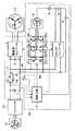
図1は、実施の形態1による、HVに搭載された負荷駆動装置の回路構成を示す回路図である。
【0030】
図1を参照して、負荷駆動装置100は、主電源1と、システム・メイン・リレー2(System Main Relay、以下SMR2と称する。)と、駆動系インバータ3と、コンデンサ4と、補機系インバータ5と、補機モータ6と、DC/DCコンバータ7と、補機バッテリ8と、リレー9,10と、制御回路11とを備える。また、SMR2は、リレー21〜23と、抵抗24とを含む。さらに、補機系インバータ5は、スイッチングトランジスタ51a〜51fと、ダイオード52a〜52fとを含む。
【0031】
主電源1は、走行用の駆動モータ14、補機負荷である補機モータ6および補機モータ6を除く補機の電源である補機バッテリ8に電力を供給する大容量のパワーキャパシタである。
【0032】
発電機12は、図示しないエンジンと接続され、エンジンから出力される機械エネルギーを電気エネルギーに変換してインバータ13へ出力し、主電源1、駆動モータ14、補機モータ6および補機バッテリ8に電力を供給する。
【0033】
インバータ13は、発電機12から出力される3相交流電圧を直流電圧に変換して主電源1や駆動モータ14などへ出力する。
【0034】
SMR2は、各負荷に電源電圧を供給する電源ラインであるノードN1,N2と主電源1とを接続/遮断するためのシステムのメインリレーである。SMR2は、制御回路11からの指令に基づいて主電源1をノードN1,N2に接続するとき、最初にリレー23および抵抗が接続されたリレー22を閉じ、その後リレー21を閉じることによって、駆動系インバータ3の前段に並列に接続された平滑コンデンサ4への突入電流を防止する。
【0035】
駆動系インバータ3は、主電源1から供給される直流電圧を3相交流電圧に変換して駆動モータ14へ出力する変換回路である。
【0036】
コンデンサ4は、駆動系インバータ3の前段に並列に接続され、電圧変動に起因する駆動系インバータ3に対しての影響を低減するための平滑コンデンサである。
【0037】
補機系インバータ5は、制御回路11によりスイッチングトランジスタ51a〜51fのスイッチング動作が制御され、主電源1から供給される直流電圧を3相交流電圧に変換して補機モータ6へ出力する変換回路である。また、補機系インバータ5は、システム起動時に主電源1の出力電圧が低下しているときは、スイッチングトランジスタ51a〜51cのスイッチング動作が制御され、後述するように、補機モータ6の巻線をリアクトルとして用いて、補機バッテリ8から出力される電圧を昇圧して主電源1を充電する。
【0038】
補機モータ6は、主電源1を直接電源とする補機用の3相交流モータであって、たとえば、電動式のA/C(エアコン)用コンプレッサなどである。補機モータ6は、補機系インバータ5から3相交流電圧が供給されて駆動する。また、補機モータ6においては、各相の巻線の一端を一括に接続して構成される中性点がリレー9を介して補機バッテリ8の正極と接続される。そして、補機モータ6は、リレー9がONされたときは、その巻線がリアクトルとして用いられ、補機系インバータ5とともに補機バッテリ8から出力される電圧を昇圧して主電源1を充電する。
【0039】
DC/DCコンバータ7は、電源ラインのノードN1,N2に駆動系インバータ3および補機系インバータ5と並列に接続され、主電源1から供給される直流電圧を所定の電圧に降圧して補機バッテリ8へ出力する。また、DC/DCコンバータ7は、主電源1から供給される直流電圧だけでなく、減速時の駆動モータ14による回生発電により発生する電圧も降圧して補機バッテリ8へ出力する。さらに、DC/DCコンバータ7は、リレー9,10が閉じられ、補機バッテリ8から補機モータ6および補機系インバータ5を介して主電源1に電力が供給されているときは、制御回路11からの指令に基づいて停止する。
【0040】
補機バッテリ8は、ランプ、小型モータその他補機用のバッテリであって、低電圧出力の二次電池である。補機バッテリ8は、DC/DCコンバータ7と接続され、主電源1から電力が供給されて充電されるほか、減速時に駆動モータ14から回生発電により発生する電力によっても充電される。また、補機バッテリ8は、正極がリレー9を介して補機モータ6の中性点に接続され、負極がリレー10を介してノードN2に接続される。そして、リレー9,10が閉じられたときは、補機バッテリ8の正極から、補機モータ6、補機系インバータ5、ノードN1、主電源1、ノードN2および補機バッテリ8の負極まで、一連の回路が構成され、補機バッテリ8から主電源1に電力が供給される。
【0041】
リレー9,10は、負荷駆動装置100の通常動作時は開状態であり、補機バッテリ8は、DC/DCコンバータ7を介してノードN1,N2から電力が供給される。一方、システム起動時に主電源1の出力電圧が低下しているときは、リレー9,10は、制御回路11からの指令に基づいて閉じられ、補機バッテリ8は、補機モータ6の中性点およびノードN2に接続される。
【0042】
制御回路11は、CPU(Central Processing Unit)、RAM(Random Access Memory)、ROM(Read Only Memory)および入出力装置(以上、いずれも図示せず)などを含むマイクロコンピュータである。制御回路11は、車両のシステムを起動するイグニッション・キーがONされると、SMR2をONにして主電源1および後述するインバータ13をノードN1,N2に接続する。これにより、主電源1およびインバータ13から各負荷への電力の供給が可能となる。そして、制御回路11は、通常動作時は、主電源1およびインバータ13から供給される電力に基づいて駆動モータ14にモータトルク指令に応じたトルクを発生させるため、駆動系インバータ3をPWM(Pulse Width Modulation)制御する。モータトルクの制御については後述する。また、制御回路11は、補機系インバータ5を制御し、これにより補機モータ6が駆動される。
【0043】
一方、制御回路11は、システムが起動され、SMR2がONされると、電圧センサ(図示せず)により検出される主電源1の出力電圧VCを入力し、電圧VCが所定の電圧V0よりも低く、負荷を駆動することができないと判断したときは、駆動系インバータ3およびDC/DCコンバータ7を停止し、リレー9,10を閉じる。そして、制御回路11は、補機バッテリ8から出力される電圧が所定の電圧に昇圧されて主電源1に供給されるように、補機系インバータ5のスイッチングトランジスタ51d〜51fをOFFにし、スイッチングトランジスタ51a〜51cのON/OFFのデューティ比を制御する。これにより、補機系インバータ5および補機モータ6の巻線によって昇圧チョッパが構成され、補機バッテリ8から出力された電圧は昇圧されて主電源1へ出力される。
【0044】
なお、スイッチングトランジスタ51a〜51cは、全て同時にON/OFF動作しても、各トランジスタが別々にサイクリックにON/OFF動作しても、あるいは、いずれかのトランジスタのみが動作するようにしてもよく、電力を供給する補機バッテリ8の容量や昇圧の程度に応じて、適切に制御される。
【0045】
一方、制御回路11は、イグニッション・キーがOFFされ、システムが停止されたと判断したときは、SMR2をOFFにして主電源1およびインバータ13を各負荷と遮断する。
【0046】
負荷駆動装置100により駆動される駆動モータ14は、走行用の3相交流誘導モータもしくは同期モータであって、駆動モータ14から発生されるモータトルクが駆動軸トルクとして車輪に伝達される。駆動モータ14は、車両が減速する場合は発電機としても使用され、減速時の回生発電により発電された電圧を主電源1に供給したり、あるいは補機モータ6や補機バッテリ8などに供給する。
【0047】
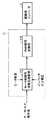
図2は、制御回路11による駆動モータ14のトルク制御を機能的に説明するための機能ブロック図である。図2を参照して、制御回路11は、モータ制御用相電圧演算部111と、PWM信号変換部112とを含む。
【0048】
モータ制御用相電圧演算部111は、モータトルク指令値と、駆動モータ14の各相の電流値と、駆動系インバータ3の入力電圧とを入力して駆動モータ14の各相コイルの電圧を演算し、PWM信号変換部112へ出力する。
【0049】
ここで、モータトルク指令値は、たとえば、アクセルペダルの開度から算出される要求パワーを達成するのに必要なモータトルク値として与えられる。本負荷駆動装置100が搭載されたシリーズHVであれば、モータトルク指令値は、必要な駆動軸トルクが出力されるように与えられる。一方、パラレルHVであれば、モータトルク指令値は、エンジントルクとモータトルクとの合計が駆動軸トルクとして出力されるように与えられる。
【0050】
また、駆動モータ14の各相の電流値は、図示しない電流センサにより検出され、駆動系インバータ3の入力電圧は、図示しない電圧センサにより検出される。
【0051】
PWM信号変換部112は、モータ制御用相電圧演算部111による演算結果に基づいて、駆動系インバータ3内の各トランジスタ(図示せず)をON/OFFするPWM信号を生成し、駆動系インバータ3へ出力する。
【0052】
このPWM信号に基づいて前記各トランジスタがスイッチング制御され、駆動モータ14の各相の駆動電流が制御され、モータトルク指令値に応じたモータトルク制御が行なわれる。
【0053】
再び図1を参照して、負荷駆動装置100においては、システムが起動されると、制御回路11からの指令によりSMR2がONされ、主電源1からノードN1,N2に電力が供給される。そして、主電源1の出力電圧VCが所定の電圧V0以上であるときは、駆動系インバータ3は、主電源1から出力された直流電圧を入力し、制御回路11から受けるPWM信号に基づいて直流電圧を3相交流電圧に変換して駆動モータ14へ出力する。これによって、駆動モータ14は指令に応じたトルクを発生する。また、補機系インバータ5およびDC/DCコンバータ7も、主電源1から出力された直流電圧を入力し、制御回路11から受ける指令に基づいて、補機系インバータ5は、入力された直流電圧を3相交流電圧に変換して補機モータ6を駆動し、DC/DCコンバータ7は、入力された直流電圧を降圧して補機バッテリ8を充電する。
【0054】
一方、システムが起動され、SMR2がONされた後、主電源1からの出力電圧VCが負荷を駆動できない程度に低下していると制御回路11により判断されたときは、制御回路11からの指令に基づいてリレー9,10が閉じられ、補機バッテリ8が補機モータ6の中性点およびノードN2に接続される。そして、制御回路11からの指令に基づいて、駆動系インバータ3およびDC/DCコンバータ7は停止し、補機系インバータ5は、制御回路11によりスイッチングトランジスタ51a〜51cのON/OFFのデューティ比が制御され、かつ、スイッチングトランジスタ51d〜51fがOFFされる。これによって、補機系インバータ5と、リアクトルとして用いられる補機モータ6の巻線とにより昇圧チョッパが構成され、補機系インバータ5は、補機バッテリ8から出力される電圧を昇圧して出力し、主電源1を充電する。
【0055】
そして、主電源1の端子間電圧VCが負荷を駆動するのに十分な電圧V1まで達したと制御回路11により判断されたときは、制御回路11からの指令に基づいてリレー9,10は開にされ、補機系インバータ5、駆動系インバータ3およびDC/DCコンバータ7は、制御回路11からの指令に基づいて通常動作を行なう。
【0056】
図3は、負荷駆動装置100において、システム起動時の制御回路11の処理を説明するためのフローチャートである。図3を参照して、システムが起動されると、制御回路11は、SMR2を上述したシーケンスでONする(ステップS1)。続いて、制御回路11は、主電源1の出力電圧VCを検出し、電圧VCが負荷を駆動するのに十分な所定の電圧V0を下回っていないかどうかをチェックする(ステップS2)。制御回路11は、電圧VCが電圧V0を下回っていると判断したときは、駆動系インバータ3およびDC/DCコンバータ7への動作指令を出力せずに停止させておき(ステップS3)、リレー9,10を閉じる(ステップS4)。そして、制御回路11は、補機系インバータ5のスイッチングトランジスタ51d〜51fをOFFし、スイッチングトランジスタ51a〜51cのデューティ比を制御して、補機バッテリ8から出力された電圧を昇圧して主電源1を充電する(ステップS5)。
【0057】
制御回路11は、主電源1の電圧VCが、各負荷への十分な電力供給が可能な所定の電圧V1を超えたと判断したときは(ステップS6)、リレー9,10を開にし(ステップS7)、主電源1から供給される電力により各負荷が駆動される通常動作に移行する(ステップS8)。一方、制御回路11は、ステップS6において、電圧VCがまだ電圧V1に達しておらず、主電源1の充電が十分でないと判断したときは、ステップS5へ戻る。
【0058】
制御回路11は、システム起動後、ステップS2において、主電源1の出力電圧VCが電圧V0以上であると判断したときは、主電源1には十分な電力が充電されているものと判断して、ステップS8へ進む。
【0059】
なお、上述した所定の電圧V0,V1は、同じであってもよいし、電圧変動により電圧V0の近傍でリレー9,10がチャタリング動作することを防止するため、V0<V1と定めてもよい。
【0060】
なお、上述した負荷駆動装置100は、シリーズ方式、パラレル方式およびシリーズ・パラレル方式のいずれのHVにも適用できる。また、HVに限定されるものではなく、EVであっても同様に適用できる。
【0061】
また、上述した主電源1は、最終的に直流電圧を出力可能な電力貯蔵装置として機能するものであればよく、たとえば2次電池などであってもよい。
【0062】
また、上述した説明においては、負荷駆動装置100がHVに搭載された場合について説明しているので、システムを起動するためのスイッチはイグニッション・キーとしているが、EVに搭載された場合には、イグニッション・キーに代えて走行許可スイッチが用いられる。
【0063】
以上のように、この実施の形態1による負荷駆動装置100によれば、HVやEVにおいて、システム起動時に主電源1の出力電圧が十分でないときは、補機バッテリ8が補機モータ6の中性点と主電源1の負極とに接続され、補機系インバータ5は、補機モータ6の巻線を用いて補機バッテリ8の出力電圧を昇圧して主電源1を充電することができるようにしたので、別体の昇圧装置や高機能の昇降圧DC/DCコンバータを備える必要がなく、低コストで主電源を充電できる。
【0064】
[実施の形態2]
実施の形態1においては、補機バッテリ8の正極は、補機モータ6の中性点に接続されたが、実施の形態2においては、補機バッテリ8の正極は、補機モータ6のいずれかの巻線の中性点を構成しないもう一端に接続される。
【0065】
図4は、実施の形態2による、HVに搭載された負荷駆動装置の回路構成を示す回路図である。
【0066】
図4を参照して、負荷駆動装置101は、補機バッテリ8の正極がリレー9を介して補機モータ6のU相の巻線の中性点を構成しない一端(ノードN3)に接続される。その他の構成は、実施の形態1において説明した負荷駆動装置100と同じである。これにより、補機系インバータ5および補機モータ6を用いて、補機バッテリ8から主電源1へ電圧を昇圧して充電する際に、リアクトルとして作用する補機モータ6の巻線を2つ使用することができ、昇圧機能をより高めることができる。
【0067】
負荷駆動装置101においては、システムが起動され、SMR2がONされた後、主電源1からの出力電圧VCが負荷を駆動できない程度に低下していると制御回路11により判断されたときは、制御回路11からの指令に基づいてリレー9,10が閉じられ、補機バッテリ8の正極が補機モータ6のU相線のノードN3に接続され、負極がノードN2に接続される。そして、制御回路11からの指令に基づいて駆動系インバータ3およびDC/DCコンバータ7は停止し、補機系インバータ5は、制御回路11によりスイッチングトランジスタ51bのみのデューティ比が制御され、その他のスイッチングトランジスタ51a,51c〜51fはOFFされる。これによって、補機系インバータ5と、リアクトルとして用いられる補機モータ6のU相およびV相の2つの巻線とにより昇圧チョッパが構成され、補機系インバータ5は、補機バッテリ8から出力される電圧を昇圧して出力し、主電源1を充電する。
【0068】
なお、補機系インバータ5は、制御回路11によりスイッチングトランジスタ51cのみのデューティ比が制御され、その他のスイッチングトランジスタ51a,51b,51d〜51fがOFFされるようにしてもよい。この場合は、補機系インバータ5は、補機モータ6のU相およびW相の2つの巻線をリアクトルとして用いることになる。
【0069】
そして、主電源1の端子間電圧VCが負荷を駆動するのに十分な電圧V1まで充電されたと制御回路11により判断されたときは、制御回路11からの指令に基づいてリレー9,10は開にされ、補機系インバータ5、駆動系インバータ3およびDC/DCコンバータ7は、制御回路11からの指令に基づいて通常動作を行なう。
【0070】
なお、上述した説明では、補機バッテリ8の正極は、補機モータ6のU相線のノードN3に接続されるものとしたが、補機バッテリ8の正極は、補機モータ6のV相線のノードN4またはW相線のノードN5に接続されるようにしてもよい。補機バッテリ8の正極がノードN4に接続されるときは、補機系インバータ5は、制御回路11によりスイッチングトランジスタ51aおよびスイッチングトランジスタ51cのいずれかのデューティ比が制御され、その他のスイッチングトランジスタはOFFされる。また、補機バッテリ8の正極がノードN5に接続されるときは、補機系インバータ5は、制御回路11によりスイッチングトランジスタ51aおよびスイッチングトランジスタ51bのいずれかのデューティ比が制御され、その他のスイッチングトランジスタはOFFされる。
【0071】
以上のように、この実施の形態2による負荷駆動装置101によれば、実施の形態1と同様に、別体の昇圧装置や高機能の昇降圧DC/DCコンバータを備える必要がなく、低コストで主電源を充電できるほか、昇圧する際に補機モータ6の巻線を2つ使用できる構成としたので、昇圧機能をより高めることができる。
【0072】
[実施の形態3]
実施の形態3による負荷駆動装置は、補機系インバータおよび補機モータが2セット備えられており、両補機モータの中性点に補機バッテリを接続して主電源1を充電するものである。
【0073】
図5は、実施の形態3による、HVに搭載された負荷駆動装置の回路構成を示す回路図である。
【0074】
図5を参照して、負荷駆動装置102は、主電源1と、SMR2と、駆動系インバータ3と、コンデンサ4と、補機系インバータ5と、補機モータ6と、DC/DCコンバータ7と、補機バッテリ8と、リレー9,10とを備え、これらについては、実施の形態1において説明した各回路と同じである。
【0075】
また、負荷駆動装置102は、補機系インバータ5Aと、補機モータ6Aとをさらに備える。さらに、補機系インバータ5Aは、スイッチングトランジスタ53a〜53fと、ダイオード54a〜54fとを含む。
【0076】
補機系インバータ5Aは、制御回路11によりスイッチングトランジスタ53a〜53fのスイッチング動作が制御され、主電源1から供給される直流電圧を3相交流電圧に変換して補機モータ6Aへ出力する変換回路である。また、補機系インバータ5Aは、システム起動時に主電源1の出力電圧が低下しているときは、リレー10を介して補機バッテリ8の負極と接続され、かつ、全てのスイッチングトランジスタ53a〜53fがOFFされ、ノードN2からダイオード54a〜54cを介して補機モータ6Aへ電流を通流する。
【0077】
補機モータ6Aは、補機モータ6と同様に、主電源1を直接電源とするもう1つの3相交流モータである。補機モータ6Aは、補機系インバータ5Aから3相交流電圧が供給されて駆動する。また、補機モータ6Aにおいては、各相の巻線の一端を一括に接続して構成される中性点がリレー10を介して補機バッテリ8の負極と接続される。そして、補機モータ6Aは、リレー10がONされたときは、補機系インバータ5Aから受ける電流を中性点から補機バッテリ8の負極へ出力する。
【0078】
制御回路11は、主電源1が補機バッテリ8から充電されるときは、実施の形態1において説明したように、補機系インバータ5のスイッチングトランジスタ51d〜51fをOFFにし、スイッチングトランジスタ51a〜51cのON/OFFのデューティ比を制御するとともに、補機系インバータ5Aのスイッチングトランジスタ53a〜53fを全てOFFにする。
【0079】
負荷駆動装置102においては、システムが起動され、SMR2がONされた後、主電源1からの出力電圧VCが負荷を駆動できない程度に低下していると制御回路11により判断されたときは、制御回路11からの指令に基づいてリレー9,10が閉じられ、補機モータ6,6Aの中性点がそれぞれ補機バッテリ8の正極および負極にそれぞれ接続される。そして、実施の形態1と同様に、補機系インバータ5のスイッチングトランジスタ51a〜51cのデューティ比が制御回路11により制御され、補機系インバータ5および補機モータ6は、補機バッテリ8から出力される電圧を昇圧して主電源1を充電する。一方、補機系インバータ5Aは、全てのスイッチングトランジスタ53a〜53fがOFFされ、補機バッテリ8と主電源1との間で回路を構成する役割を担う。すなわち、実施の形態3においては、補機バッテリ8と主電源1との間には、補機バッテリ8の正極から、補機モータ6、補機系インバータ5、ノードN1、主電源1、ノードN2、補機系インバータ5A(ダイオード54a〜54c)、補機モータ6Aおよび補機バッテリ8の負極まで、一連の回路が構成される。
【0080】
負荷駆動装置102におけるその他の動作については、実施の形態1による負荷駆動装置100と同様であり、説明は省略する。
【0081】
なお、上述した説明においては、補機バッテリ8は、リレー9,10を介して補機モータ6,6Aの中性点に接続されたが、実施の形態1に対応する実施の形態2と同様に、補機バッテリ8は、補機モータ6,6Aのそれぞれにおけるいずれかの巻線において、中性点を構成しない一端に接続されるようにしてもよい。その場合の補機系インバータ5におけるスイッチングトランジスタの動作は、実施の形態2において説明したとおりである。
【0082】
なお、図示しないが、この実施の形態3のように、補機系インバータが2つ備えられている負荷駆動装置においては、外部商用電源を補機系インバータ5,5Aのそれぞれの中性点に接続し、入力される交流電圧の位相に同期して補機系インバータ5,5Aのスイッチングを交互に適切に制御すれば、外部商用電源から入力される交流電圧を直流電圧に変換し、かつ、昇圧して主電源1を充電することもできる。
【0083】
以上のように、実施の形態3による負荷駆動装置102によっても、実施の形態1と同様に、別体の昇圧装置や高機能の昇降圧DC/DCコンバータを備える必要がなく、低コストで主電源を充電できる。
【0084】
今回開示された実施の形態は、すべての点で例示であって制限的なものではないと考えられるべきである。本発明の範囲は、上記した実施の形態の説明ではなくて特許請求の範囲によって示され、特許請求の範囲と均等の意味および範囲内でのすべての変更が含まれることが意図される。
【図面の簡単な説明】
【図1】 この発明の実施の形態1による負荷駆動装置の回路構成を示す回路図である。
【図2】 図1に示す負荷駆動装置における制御回路による駆動モータのトルク制御を機能的に説明するための機能ブロック図である。
【図3】 図1に示す負荷駆動装置における制御回路のシステム起動時の処理を説明するためのフローチャートである。
【図4】 この発明の実施の形態2による負荷駆動装置の回路構成を示す回路図である。
【図5】 この発明の実施の形態3による負荷駆動装置の回路構成を示す回路図である。
【符号の説明】
1 主電源、2 SMR、3 駆動系インバータ、4 コンデンサ、5,5A補機系インバータ、6,6A 補機モータ、7 DC/DCコンバータ、8 補機バッテリ、9,10,21〜23 リレー、11 制御回路、12 発電機、13 インバータ、14 駆動モータ、24 抵抗、51a〜51f,53a〜53f スイッチングトランジスタ、52a〜52f,54a〜54f ダイオード、100〜102 負荷駆動装置、N1〜N5 ノード。[0001]
BACKGROUND OF THE INVENTION
The present invention relates to a load drive device, a charge control method for a power storage device in the load drive device, and a computer-readable recording medium on which a program for causing a computer to execute charge control is recorded, particularly in a hybrid vehicle and an electric vehicle. A load driving device having a mechanism for charging the power storage device when the charging state of the power storage device used as a main power source is lowered at the time of starting the system, and charging control of the power storage device in the load driving device The present invention relates to a method and a computer-readable recording medium on which a program for causing a computer to execute charging control is recorded.
[0002]
[Prior art]
In the background of energy saving and environmental problems that have been increasing in recent years, hybrid vehicles (hereinafter referred to as HV) and electric vehicles (hereinafter referred to as EV) have attracted a great deal of attention. These vehicles include a power storage device such as a power capacitor or a secondary battery mounted on the vehicle, and run by driving a motor using this as a power source.
[0003]
In these vehicles, when the discharge from the power storage device (hereinafter referred to as the main power source) as the power source proceeds remarkably and the remaining capacity of the main power source decreases, the main power source is charged by some means. There is a need to. In particular, when a power capacitor is used for the main power supply, the amount of self-discharge is large. Therefore, when starting the system after a long period of non-use, the system starts up due to insufficient output voltage of the main power supply. It is easy to happen.
[0004]
Conventionally, when the main power supply charge condition has been reduced due to long periods of non-use of the vehicle, etc., and the system cannot be started, the AC voltage of an external commercial AC power supply can be used as a means of charging the main power supply. Is converted into a DC voltage by an external charger and charged.
[0005]
On the other hand, the vehicle described above is provided with an auxiliary battery that supplies electric power to an auxiliary load such as a lamp, a small motor, and a control circuit in addition to a main power source. This auxiliary battery is equivalent to an alternator in a conventional engine-driven vehicle. However, in EV, there is no engine as a mechanical energy source, and in HV, an improvement in fuel consumption, an idle stop system when the vehicle is stopped, etc. Therefore, in EV and HV, the auxiliary battery is supplied with electric power from the main power source (when the vehicle is braked, electric power is also supplied from the drive motor by regenerative power generation). .)
[0006]
All of the above-described auxiliary machine loads operate at a low voltage of a few tens of volts, and the auxiliary battery also outputs a voltage corresponding thereto. On the other hand, since the main power source is used as a power source of the vehicle, it normally outputs a voltage of several hundred volts. Therefore, a DC / DC converter that charges the auxiliary battery by reducing the voltage output from the high-voltage main power supply to the auxiliary system voltage is usually provided.
[0007]
Japanese Patent No. 3141777 discloses a motor drive system for a series HV vehicle having such a DC / DC converter. That is, the auxiliary battery is connected to the main battery via the DC / DC converter, and the DC / DC converter steps down the power supply voltage output from the main battery to the voltage of the auxiliary system between the positive and negative terminals of the auxiliary battery. Apply to.
[0008]
In the case of a system including a DC / DC converter that connects such a main power source and an auxiliary battery, as described above, the power supply capability of the main power source decreases due to long-term non-use and the like, and the system is started. When this becomes impossible, it can be considered that the main power supply is charged from the auxiliary battery via the DC / DC converter. However, the purpose of providing the DC / DC converter in the above-described system is to use the power output from the main power source or the power generated by the regenerative power generation from the drive motor as the power supply source of the auxiliary battery, and these are high voltage. This is because it is necessary to step down the voltage corresponding to the voltage of the auxiliary load when the auxiliary battery is supplied, and generally such a DC / DC converter does not have a step-up function. Therefore, when charging the main power source using an auxiliary battery, a method of charging using a separate boost converter has been conventionally used.
[0009]
[Problems to be solved by the invention]
However, as a means for charging the main power supply, the means for charging by converting the AC voltage of the external commercial power supply to a DC voltage by an external charger requires an external charger having an AC / DC converter function, and the total The cost cannot be reduced.
[0010]
In addition, a system including a DC / DC converter connected between the main power supply and the auxiliary battery requires a separate boost converter, and the total cost is the same as in the case of the external charger. Cannot be reduced.
[0011]
Furthermore, it is conceivable to use a step-up / step-down type DC / DC converter and charge the main power source from the auxiliary battery by boosting control when the main power source charge state decreases, but it also has a step-up / step-down function. Adoption of a high-functional DC / DC converter is a factor that increases costs.
[0012]
Therefore, the present invention has been made to solve such a problem, and its purpose is to supply power from the auxiliary battery to the main power supply when the charge state of the main power supply is reduced at the time of system startup. It is an object of the present invention to provide a load driving device capable of realizing the function to be performed at low cost.
[0013]
Another object of the present invention is to provide a load that can realize a function of supplying power from the auxiliary battery to the main power supply at a low cost when the charge state of the main power supply is lowered at the time of starting the system. It is providing the charge control method of the electric power storage apparatus in a drive device.
[0014]
Furthermore, another object of the present invention is to provide a load capable of realizing a function of supplying power from the auxiliary battery to the main power supply at a low cost when the charge state of the main power supply is lowered at the time of starting the system. The present invention provides a computer-readable recording medium in which a program for causing a computer to execute a charging control method for a power storage device in a driving device is recorded.
[0015]
[Means for Solving the Problems]
According to this invention, the load driving device includes an AC motor, a first power source that outputs a first voltage that is a DC voltage, a second power source that outputs a second voltage that is a DC voltage, 1 voltage is input and converted to AC voltage, AC voltage is output to the AC motor to drive the AC motor, the first voltage is stepped down and output to the second power source, and the second power source And a control circuit, and when the first voltage is lower than a predetermined voltage, the second voltage is input to the winding of the AC motor, and the control circuit includes the winding of the AC motor and the inverter. As a result, the second voltage is boosted and output to the first power source, the inverter is controlled so that the first power source is charged, and the converter is stopped.
[0016]
Preferably, the second voltage is input to a neutral point configured by connecting all ends of all windings of the AC motor together.
[0017]
Preferably, the second voltage is input to one end of one of the windings of the AC motor on the side opposite to the neutral point configured by connecting all ends of all windings of the AC motor together.
[0018]
Preferably, the load driving device inputs the first voltage and converts it into another AC voltage, and outputs the other AC voltage to the traveling vehicle driving motor to drive the vehicle driving motor. The inverter further includes one inverter, and the AC motor is an auxiliary motor. When the first voltage is lower than the predetermined voltage, the control circuit further stops the other inverter.
[0019]
Preferably, the AC motor includes a first AC motor and a second AC motor, and the inverter receives the first voltage and converts it into the first AC voltage, and the first AC voltage is converted into the first AC voltage. A first inverter that outputs to the first AC motor and drives the first AC motor; and a first voltage that is input to convert the second AC voltage to the second AC motor; When the first voltage is lower than a predetermined voltage, the positive electrode of the second power source is connected to all windings of the first AC motor. A second neutral point is formed by connecting one end of the wire in a lump to the first neutral point, and the negative electrode is formed by lump connecting all ends of all windings of the second AC motor. Connected to the point, the control circuit is connected to the second voltage by the winding of the first AC motor and the first inverter. Output is boosted to the first power supply, the first power supply controls the first inverter to be charged.
[0020]
Preferably, the first power source is either a power capacitor or a secondary battery.
[0021]
Preferably, when the first power supply needs to be charged at the time of starting the system, the control circuit boosts the second voltage by the winding of the AC motor and the inverter and outputs the boosted voltage to the first power supply. The inverter is controlled so that is charged, and the converter is stopped.
[0022]
According to this invention, the charge control method for the power storage device in the load driving device is the step-down operation of the first voltage in the load driving device that drives the load with the first voltage output from the first DC power supply. A charging control method for a power storage device in a load driving device, wherein the first DC power source is charged with a second voltage output from the second DC power source charged in the charging, and charging the first DC power source Is required to switch from a power supply route for stepping down the first voltage and charging the second DC power supply to another power supply route for stepping up the second voltage and charging the first DC power supply. 1, a second step of inputting a second voltage and boosting the voltage, and a third step of charging the first DC power supply by outputting the boosted second voltage to the first DC power supply With.
[0023]
Preferably, the second voltage is input to the winding of the AC motor driven by the first voltage, and controls the switching of at least one switching transistor of the inverter that drives the AC motor so as to control the winding of the AC motor. The second voltage is boosted in the second step by the inverter.
[0024]
Further, according to the present invention, the recording medium is a second DC that is charged by stepping down the first voltage in the load driving device that drives the load by the first voltage output from the first DC power supply. A computer-readable recording medium that records a program for causing a computer to execute charging control of a power storage device in a load driving device, which charges a first DC power source with a second voltage output from a power source, When the first DC power supply needs to be charged, the second voltage is boosted to charge the first DC power supply from the power supply route that steps down the first voltage and charges the second DC power supply. A first step of switching to one power supply route; a second step of inputting and boosting a second voltage; and outputting the boosted second voltage to the first DC power source to generate a first DC power source 3rd step to charge Recording a program for executing the up to the computer.
[0025]
Preferably, the second voltage is input to the winding of the AC motor driven by the first voltage, and controls the switching of at least one switching transistor of the inverter that drives the AC motor so as to control the winding of the AC motor. The second voltage is boosted in the second step by the inverter.
[0026]
As described above, according to the load driving device and the charge control method for the power storage device in the load driving device according to the present invention, when the output voltage of the main power source is not sufficient at the time of system startup in HV or EV, the auxiliary battery is Connected to the neutral point of the auxiliary motor and the negative pole of the main power supply, the auxiliary system inverter can boost the output voltage of the auxiliary battery using the winding of the auxiliary motor to charge the main power supply Since it did in this way, it is not necessary to provide a separate booster and a high-performance step-up / step-down DC / DC converter, and the main power supply can be charged at low cost.
[0027]
Further, according to the load driving device and the charge control method for the power storage device in the load driving device according to the present invention, the single-phase AC voltage input from the external commercial power source is converted into DC by the two sets of auxiliary inverters and auxiliary motors. Since the main power supply can be charged by converting to voltage and boosting, it is not necessary to provide a separate converter, and the main power supply can be charged at low cost.
[0028]
DETAILED DESCRIPTION OF THE INVENTION
Hereinafter, embodiments of the present invention will be described in detail with reference to the drawings. In the drawings, the same or corresponding parts are denoted by the same reference numerals and description thereof will not be repeated.
[0029]
[Embodiment 1]
FIG. 1 is a circuit diagram showing a circuit configuration of a load driving device mounted on an HV according to the first embodiment.
[0030]
Referring to FIG. 1, a
[0031]
The
[0032]
The
[0033]
The
[0034]
The
[0035]
The
[0036]
The
[0037]
The
[0038]
The
[0039]
The DC /
[0040]
The
[0041]
[0042]
The
[0043]
On the other hand, the
[0044]
Note that the switching
[0045]
On the other hand, when it is determined that the ignition key is turned off and the system is stopped, the
[0046]
The
[0047]
FIG. 2 is a functional block diagram for functionally explaining the torque control of the
[0048]
The motor control phase
[0049]
Here, the motor torque command value is given as, for example, a motor torque value necessary to achieve the required power calculated from the opening of the accelerator pedal. If the
[0050]
The current value of each phase of the
[0051]
The
[0052]
Based on the PWM signal, the transistors are subjected to switching control, the drive current of each phase of the
[0053]
Referring to FIG. 1 again, in the
[0054]
On the other hand, when the
[0055]
When the
[0056]
FIG. 3 is a flowchart for explaining processing of the
[0057]
When the
[0058]
When the
[0059]
The predetermined voltages V0 and V1 described above may be the same, or may be set as V0 <V1 in order to prevent the
[0060]
Note that the above-described
[0061]
Further, the
[0062]
Further, in the above description, since the case where the
[0063]
As described above, according to the
[0064]
[Embodiment 2]
In the first embodiment, the positive electrode of the
[0065]
FIG. 4 is a circuit diagram showing a circuit configuration of the load driving device mounted on the HV according to the second embodiment.
[0066]
Referring to FIG. 4,
[0067]
In the
[0068]
In the
[0069]
When the
[0070]
In the above description, the positive electrode of
[0071]
As described above, according to the
[0072]
[Embodiment 3]
The load drive device according to the third embodiment is provided with two sets of an auxiliary system inverter and an auxiliary motor, and charges the
[0073]
FIG. 5 is a circuit diagram showing a circuit configuration of the load driving device mounted on the HV according to the third embodiment.
[0074]
Referring to FIG. 5, load
[0075]
The
[0076]
The
[0077]
Similar to the
[0078]
When the
[0079]
In the
[0080]
Other operations in the
[0081]
In the above description, the
[0082]
Although not shown, in the load driving apparatus having two auxiliary system inverters as in the third embodiment, the external commercial power source is set to the neutral point of each of the
[0083]
As described above, the
[0084]
The embodiment disclosed this time should be considered as illustrative in all points and not restrictive. The scope of the present invention is shown not by the above description of the embodiments but by the scope of claims for patent, and is intended to include meanings equivalent to the scope of claims for patent and all modifications within the scope.
[Brief description of the drawings]
FIG. 1 is a circuit diagram showing a circuit configuration of a load driving device according to
2 is a functional block diagram for functionally explaining torque control of a drive motor by a control circuit in the load drive device shown in FIG. 1; FIG.
FIG. 3 is a flowchart for explaining processing at the time of system startup of a control circuit in the load driving device shown in FIG. 1;
FIG. 4 is a circuit diagram showing a circuit configuration of a load driving device according to
FIG. 5 is a circuit diagram showing a circuit configuration of a load driving device according to
[Explanation of symbols]
1 main power supply, 2 SMR, 3 drive system inverter, 4 capacitor, 5, 5A auxiliary machine inverter, 6, 6A auxiliary motor, 7 DC / DC converter, 8 auxiliary battery, 9, 10, 21-23 relay, DESCRIPTION OF
Claims (11)
Translated fromJapanese直流電圧である第1の電圧を出力する第1の電源と、
直流電圧である第2の電圧を出力する第2の電源と、
前記第1の電源と前記交流モータとの間に配設され、前記第1の電圧を受けて前記交流モータを駆動可能に構成されたインバータと、
前記第1の電源と前記第2の電源との間に配設され、前記第1の電圧を降圧して前記第2の電源を充電可能に構成されたコンバータと、
前記交流モータと異なる走行用の車両駆動用モータと、
前記第1の電源と前記車両駆動用モータとの間に配設され、前記第1の電圧を受けて前記車両駆動用モータを駆動可能に構成されたもう1つのインバータと、
制御回路とを備え、
前記交流モータは、補機用モータであり、
前記第1の電圧が所定の電圧よりも低いとき、
前記第2の電圧が前記交流モータの巻線に入力され、
前記制御回路は、前記インバータを制御することによって、前記交流モータの巻線および前記インバータにより前記第2の電圧を昇圧して前記第1の電源の充電を実行し、前記コンバータを停止するとともに前記もう1つのインバータをさらに停止する、負荷駆動装置。An AC motor,
A first power supply that outputs a first voltage that is a DC voltage;
A second power source that outputs a second voltage that is a DC voltage;
An inverterdisposed between the first power source and the AC motor, configured to receive the first voltage and drive the AC motor ;
A converter disposed between the first power source and the second power source, configured to step down the first voltage and charge the second power source ;
A vehicle drive motor for traveling different from the AC motor;
Another inverter disposed between the first power source and the vehicle drive motor and configured to receive the first voltage and drive the vehicle drive motor;
A control circuit,
The AC motor is an auxiliary motor,
When the first voltage is lower than a predetermined voltage,
The second voltage is input to the winding of the AC motor;
The control circuitcontrols the inverter, boosts the second voltage by the winding of the AC motor and the inverter, performs charging of the first power source, stops the converter and A load drive devicethat further stops the other inverter .
直流電圧である第1の電圧を出力する第1の電源と、
直流電圧である第2の電圧を出力する第2の電源と、
前記第1の電源と前記交流モータとの間に配設され、前記第1の電圧を受けて前記交流モータを駆動可能に構成されたインバータと、
前記第1の電源と前記第2の電源との間に配設され、前記第1の電圧を降圧して前記第2の電源を充電可能に構成されたコンバータと、
制御回路とを備え、
前記第1の電圧が所定の電圧よりも低いとき、
前記第2の電圧は、前記交流モータのいずれかの巻線における、前記交流モータの全ての巻線の一端が一括に接続されて構成される中性点と反対側の一端に入力され、
前記制御回路は、前記インバータを制御することによって、前記交流モータの巻線および前記インバータにより前記第2の電圧を昇圧して前記第1の電源の充電を実行し、前記コンバータを停止する、負荷駆動装置。An AC motor,
A first power supply that outputs a first voltage that is a DC voltage;
A second power source that outputs a second voltage that is a DC voltage;
An inverterdisposed between the first power source and the AC motor, configured to receive the first voltage and drive the AC motor ;
A converter disposed between the first power source and the second power source, configured to step down the first voltage and charge the second power source ;
A control circuit,
When the first voltage is lower than a predetermined voltage,
The second voltage is input to one end of the winding of the AC motor opposite to the neutral point configured by collectively connecting one end of all windings of the AC motor,
The control circuit controls the inverter, boosts the second voltage by the winding of the AC motor and the inverter, performs charging of the first power source, and stops the converter. Drive device.
直流電圧である第1の電圧を出力する第1の電源と、
直流電圧である第2の電圧を出力する第2の電源と、
前記第1の電源と前記交流モータとの間に配設され、前記第1の電圧を受けて前記交流モータを駆動可能に構成されたインバータと、
前記第1の電源と前記第2の電源との間に配設され、前記第1の電圧を降圧して前記第2の電源を充電可能に構成されたコンバータと、
制御回路とを備え、
前記交流モータは、
第1の交流モータと、
第2の交流モータとからなり、
前記インバータは、
前記第1の電源と前記第1の交流モータとの間に配設され、前記第1の電圧を受けて前記第1の交流モータを駆動可能に構成された第1のインバータと、
前記第1の電源と前記第2の交流モータとの間に配設され、前記第1の電圧を受けて前記第2の交流モータを駆動可能に構成された第2のインバータとからなり、
前記第1の電圧が所定の電圧よりも低いとき、
前記第2の電源の正極が、前記第1の交流モータの全ての巻線の一端が一括に接続されて構成される第1の中性点に、かつ、負極が前記第2の交流モータの全ての巻線の一端が一括に接続されて構成される第2の中性点に接続され、
前記制御回路は、前記第1のインバータを制御することによって、前記第1の交流モータの巻線および前記第1のインバータにより前記第2の電圧を昇圧して前記第1の電源の充電を実行し、前記コンバータを停止する、負荷駆動装置。An AC motor,
A first power supply that outputs a first voltage that is a DC voltage;
A second power source that outputs a second voltage that is a DC voltage;
An inverterdisposed between the first power source and the AC motor, configured to receive the first voltage and drive the AC motor ;
A converter disposed between the first power source and the second power source, configured to step down the first voltage and charge the second power source ;
A control circuit,
The AC motor is
A first AC motor;
Consisting of a second AC motor,
The inverter is
A first inverter disposed between the first power source and the first AC motor and configured to receive the first voltage and drive the first AC motor ;
Wherein said first power supply is disposed between the second AC motor, it consists of afirst of the second inverterdriven configured to be able topre-Symbol second ACmotorreceives voltage,
When said first voltageis lower thanJo Tokoro voltage,
The positive electrode of the second power source is at a first neutral point configured by collectively connecting one ends of all the windings of the first AC motor, and the negative electrode is of the second AC motor. One end of all windings is connected to a second neutral point that is configured by being connected together,
The control circuit controlsthe first inverter to boost the second voltage by the winding of the first AC motor and the first inverter to charge the first power source. And a load driving devicefor stopping the converter .
前記第1の電源と前記車両駆動用モータとの間に配設され、前記第1の電圧を受けて前記車両駆動用モータを駆動可能に構成されたもう1つのインバータとをさらに備え、And further comprising another inverter disposed between the first power source and the vehicle driving motor and configured to receive the first voltage and to drive the vehicle driving motor.
前記交流モータは、補機用モータであり、The AC motor is an auxiliary motor,
前記第1の電圧が前記所定の電圧よりも低いとき、前記制御回路は、前記もう1つのインバータをさらに停止する、請求項3または請求項4に記載の負荷駆動装置。5. The load driving device according to claim 3, wherein when the first voltage is lower than the predetermined voltage, the control circuit further stops the another inverter. 6.
前記制御回路は、前記インバータを制御することによって、前記交流モータの巻線および前記インバータにより前記第2の電圧を昇圧して前記第1の電源の充電を実行し、前記コンバータを停止する、請求項1から請求項6のいずれか1項に記載の負荷駆動装置。When the first power source needs to be charged at system startup,
The control circuitcontrols the inverter, boosts the second voltage by the winding of the AC motor and the inverter, executes the charging of the first power supply, and stops the converter. The load driving device according to any one of claims 1 to 6.
前記第1の直流電源の充電が必要であるとき、前記第1の電圧を降圧して前記第2の直流電源を充電する電源ルートから、前記第2の電圧を昇圧して前記第1の直流電源を充電するもう1つの電源ルートに切替えるステップと、
前記第2の電圧を入力して昇圧するステップと、
前記昇圧された第2の電圧を前記第1の直流電源へ出力して前記第1の直流電源を充電するステップと、
前記第1の直流電源から前記第1の電圧を受けて走行用の車両駆動用モータを駆動可能に構成されたインバータを停止するステップとを備える、負荷駆動装置における電力貯蔵装置の充電制御方法。In a load driving apparatus that drives a load with a first voltage output from a first DC power supply, the second voltage output from a second DC power supply charged by stepping down the first voltage A charge control method for a power storage device in a load driving device for charging a first DC power source,
When the first DC power supply needs to be charged, the first voltage is stepped up from the power supply route for charging the second DC power supply by stepping down the first voltage. andLuz step switch to another power supply route to charge the power supply,
AndLuz step to boost enter the second voltage,
AndLuz steps to charge the first DC power supply and outputs a second voltage that is the boost to the first DC powersupply,
A charge control method for a power storage device in a load driving device, comprising:a step of stopping an inverter configured to receive the first voltage from the first DC power supply and drive a vehicle driving motor for traveling .
前記第2の電圧を入力して昇圧するステップにおいて、前記交流モータを駆動するインバータの少なくとも1つのスイッチングトランジスタのスイッチングを制御して、前記交流モータの巻線および前記インバータにより前記第2の電圧を昇圧する、請求項8に記載の負荷駆動装置における電力貯蔵装置の充電制御方法。The second voltage is input to a winding of an AC motor driven by the first voltage,
In the step of boosting by inputting the second voltage, the AC controls the switching of the at least one switching transistor of the inverter for driving the motor, the AC motor windings and byRi before Symbol second to the inverter The charge control method for the power storage device in the load driving device according to claim 8, wherein the voltage is increased.
前記第1の直流電源の充電が必要であるとき、前記第1の電圧を降圧して前記第2の直流電源を充電する電源ルートから、前記第2の電圧を昇圧して前記第1の直流電源を充電するもう1つの電源ルートに切替えるステップと、
前記第2の電圧を入力して昇圧するステップと、
前記昇圧された第2の電圧を前記第1の直流電源へ出力して前記第1の直流電源を充電するステップと、
前記第1の直流電源から前記第1の電圧を受けて走行用の車両駆動用モータを駆動可能に構成されたインバータを停止するステップとをコンピュータに実行させるためのプログラムを記録したコンピュータ読取可能な記録媒体。In a load driving apparatus that drives a load with a first voltage output from a first DC power supply, the second voltage output from a second DC power supply charged by stepping down the first voltage A computer-readable recording medium that records a program for causing a computer to execute charge control of a power storage device in a load driving device for charging a first DC power source,
When the first DC power supply needs to be charged, the first voltage is stepped up from the power supply route for charging the second DC power supply by stepping down the first voltage. andLuz step switch to another power supply route to charge the power supply,
AndLuz step to boost enter the second voltage,
AndLuz steps to charge the first DC power supply and outputs a second voltage that is the boost to the first DC powersupply,
A computer-readable recording of a program for causing a computer to executea step of stopping an inverter configured to receive the first voltage from the first DC power source and drive a vehicle driving motor for traveling. recoding media.
前記第2の電圧を入力して昇圧するステップにおいて、前記交流モータを駆動するインバータの少なくとも1つのスイッチングトランジスタのスイッチングを制御して、前記交流モータの巻線および前記インバータにより前記第2の電圧を昇圧する、請求項10に記載の記録媒体。The second voltage is input to a winding of an AC motor driven by the first voltage,
In the step of boosting by inputting the second voltage, the AC controls the switching of the at least one switching transistor of the inverter for driving the motor, the AC motor windings and byRi before Symbol second to the inverter The recording medium according to claim 10, wherein the voltage is increased.
Priority Applications (2)
| Application Number | Priority Date | Filing Date | Title |
|---|---|---|---|
| JP2002028242AJP4023171B2 (en) | 2002-02-05 | 2002-02-05 | LOAD DRIVE DEVICE, CHARGE CONTROL METHOD FOR POWER STORAGE DEVICE IN LOAD DRIVE DEVICE, AND COMPUTER-READABLE RECORDING MEDIUM CONTAINING PROGRAM FOR CAUSING COMPUTER TO EXECUTE CHARGE CONTROL |
| US10/351,496US6930460B2 (en) | 2002-02-05 | 2003-01-27 | Load driver with power storage unit |
Applications Claiming Priority (1)
| Application Number | Priority Date | Filing Date | Title |
|---|---|---|---|
| JP2002028242AJP4023171B2 (en) | 2002-02-05 | 2002-02-05 | LOAD DRIVE DEVICE, CHARGE CONTROL METHOD FOR POWER STORAGE DEVICE IN LOAD DRIVE DEVICE, AND COMPUTER-READABLE RECORDING MEDIUM CONTAINING PROGRAM FOR CAUSING COMPUTER TO EXECUTE CHARGE CONTROL |
Publications (2)
| Publication Number | Publication Date |
|---|---|
| JP2003235105A JP2003235105A (en) | 2003-08-22 |
| JP4023171B2true JP4023171B2 (en) | 2007-12-19 |
Family
ID=27654645
Family Applications (1)
| Application Number | Title | Priority Date | Filing Date |
|---|---|---|---|
| JP2002028242AExpired - Fee RelatedJP4023171B2 (en) | 2002-02-05 | 2002-02-05 | LOAD DRIVE DEVICE, CHARGE CONTROL METHOD FOR POWER STORAGE DEVICE IN LOAD DRIVE DEVICE, AND COMPUTER-READABLE RECORDING MEDIUM CONTAINING PROGRAM FOR CAUSING COMPUTER TO EXECUTE CHARGE CONTROL |
Country Status (2)
| Country | Link |
|---|---|
| US (1) | US6930460B2 (en) |
| JP (1) | JP4023171B2 (en) |
Cited By (1)
| Publication number | Priority date | Publication date | Assignee | Title |
|---|---|---|---|---|
| CN102737000A (en)* | 2011-03-08 | 2012-10-17 | Ls产电株式会社 | Data transfer apparatus and method |
Families Citing this family (89)
| Publication number | Priority date | Publication date | Assignee | Title |
|---|---|---|---|---|
| EP1414145B1 (en)* | 2001-08-02 | 2019-12-25 | Toyota Jidosha Kabushiki Kaisha | Motor drive control apparatus |
| JP3632657B2 (en)* | 2001-12-20 | 2005-03-23 | トヨタ自動車株式会社 | Voltage converter |
| DE60334164D1 (en)* | 2002-07-12 | 2010-10-21 | Toyota Motor Co Ltd | A method and apparatus for controlling whether an auxiliary power supply powered by a polyphase motor is turned off |
| JP3582523B2 (en)* | 2002-09-17 | 2004-10-27 | トヨタ自動車株式会社 | Electric load device, abnormality processing method, and computer-readable recording medium recording a program for causing a computer to execute electric load abnormality processing |
| JP2004236424A (en)* | 2003-01-30 | 2004-08-19 | Toyota Motor Corp | POWER OUTPUT DEVICE, MOTOR DRIVE METHOD, AND COMPUTER-READABLE RECORDING MEDIUM RECORDING PROGRAM FOR CAUSING COMPUTER TO EXECUTE DRIVE CONTROL OF MOTOR |
| JP2004336885A (en)* | 2003-05-07 | 2004-11-25 | Toyota Motor Corp | POWER OUTPUT DEVICE, MOTOR DRIVE METHOD, AND COMPUTER-READABLE RECORDING MEDIUM RECORDING PROGRAM FOR CAUSING COMPUTER TO EXECUTE DRIVE CONTROL OF MOTOR |
| JP4063192B2 (en)* | 2003-10-23 | 2008-03-19 | 日産自動車株式会社 | Control device for motor-driven 4WD vehicle |
| JP4063199B2 (en)* | 2003-11-14 | 2008-03-19 | 日産自動車株式会社 | Control device for motor-driven 4WD vehicle |
| JP3969385B2 (en) | 2003-11-27 | 2007-09-05 | 日産自動車株式会社 | Control device and control method for motor-driven 4WD vehicle |
| JP4082338B2 (en)* | 2003-11-27 | 2008-04-30 | 日産自動車株式会社 | Control device and control method for motor-driven 4WD vehicle |
| JP4461824B2 (en) | 2004-02-13 | 2010-05-12 | トヨタ自動車株式会社 | Vehicle, vehicle control method, and computer-readable recording medium recording a program for causing a computer to execute the control method |
| JP4140552B2 (en)* | 2004-04-28 | 2008-08-27 | トヨタ自動車株式会社 | Automotive power supply device and automobile equipped with the same |
| EP1779503A2 (en)* | 2004-07-05 | 2007-05-02 | Moteurs Leroy-Somer | Rectifier and system for controlling the speed of an electric motor |
| JP4430501B2 (en)* | 2004-09-29 | 2010-03-10 | トヨタ自動車株式会社 | Power output apparatus and vehicle equipped with the same |
| JP4055766B2 (en)* | 2004-10-18 | 2008-03-05 | トヨタ自動車株式会社 | Hybrid vehicle and control method thereof |
| JP4245546B2 (en)* | 2004-11-04 | 2009-03-25 | トヨタ自動車株式会社 | Power output apparatus and vehicle equipped with the same |
| JP4679891B2 (en)* | 2004-11-30 | 2011-05-11 | トヨタ自動車株式会社 | AC voltage generator and power output device |
| JP2006187090A (en)* | 2004-12-27 | 2006-07-13 | Nissan Motor Co Ltd | Generator power control device |
| JP2006280109A (en)* | 2005-03-29 | 2006-10-12 | Mitsubishi Fuso Truck & Bus Corp | Voltage converting circuit for electric vehicle |
| KR100757060B1 (en)* | 2005-04-01 | 2007-09-10 | 엘지전자 주식회사 | SR generator with improved generation efficiency at low speed |
| JP2006315660A (en) | 2005-04-13 | 2006-11-24 | Nissan Motor Co Ltd | Vehicle drive control device |
| JP4635710B2 (en)* | 2005-05-11 | 2011-02-23 | トヨタ自動車株式会社 | AC voltage output device |
| JP4285458B2 (en)* | 2005-08-08 | 2009-06-24 | トヨタ自動車株式会社 | Vehicle power supply apparatus and control method thereof |
| JP4682740B2 (en)* | 2005-08-08 | 2011-05-11 | トヨタ自動車株式会社 | Vehicle power supply |
| US7554276B2 (en)* | 2005-09-21 | 2009-06-30 | International Rectifier Corporation | Protection circuit for permanent magnet synchronous motor in field weakening operation |
| JP4591294B2 (en)* | 2005-09-21 | 2010-12-01 | トヨタ自動車株式会社 | Electric power control apparatus and electric vehicle equipped with the same |
| JP4337797B2 (en)* | 2005-09-29 | 2009-09-30 | トヨタ自動車株式会社 | Power control device and electric vehicle |
| US7560904B2 (en)* | 2005-10-03 | 2009-07-14 | Lear Corporation | Method and system of managing power distribution in switch based circuits |
| US7923965B2 (en)* | 2005-10-10 | 2011-04-12 | General Electric Company | Methods for coupling an energy storage system to a variable energy supply system |
| JP2007237905A (en)* | 2006-03-08 | 2007-09-20 | Denso Corp | Program rewriting system for hybrid type vehicle and electronic control device |
| JP4925181B2 (en)* | 2006-03-09 | 2012-04-25 | 国立大学法人長岡技術科学大学 | Power system |
| JP4702155B2 (en)* | 2006-04-14 | 2011-06-15 | トヨタ自動車株式会社 | Power supply device and control method of power supply device |
| US7808195B2 (en)* | 2006-05-15 | 2010-10-05 | Mitsubishi Electric Corporation | Control apparatus for electric train |
| JP4211806B2 (en)* | 2006-06-07 | 2009-01-21 | トヨタ自動車株式会社 | Vehicle drive system and vehicle equipped with the same |
| JP4179351B2 (en)* | 2006-07-07 | 2008-11-12 | トヨタ自動車株式会社 | Power supply system, vehicle equipped with the same, method for controlling power supply system, and computer-readable recording medium recording a program for causing computer to execute control of power supply system |
| JP4529959B2 (en)* | 2006-08-24 | 2010-08-25 | マツダ株式会社 | Control device for hybrid vehicle |
| JP4600390B2 (en)* | 2006-12-14 | 2010-12-15 | トヨタ自動車株式会社 | Power supply system, vehicle including the same, and control method thereof |
| JP4179378B2 (en)* | 2007-01-04 | 2008-11-12 | トヨタ自動車株式会社 | VEHICLE DRIVE CONTROL DEVICE AND VEHICLE |
| CA2677847C (en)* | 2007-02-09 | 2015-08-11 | A123 Systems, Inc. | Control system for hybrid vehicles with reconfigurable multi-function power converter |
| FR2915722B1 (en)* | 2007-05-03 | 2009-08-28 | Renault Sas | "DEVICE AND METHOD FOR CONTROLLING A POWER DERIVATION CIRCUIT, HYBRID VEHICLE HAVING THE SAME" |
| FR2921771B1 (en)* | 2007-10-01 | 2014-12-12 | Valeo Systemes De Controle Moteur | POWER SUPPLY SYSTEM OF ELECTRIC MACHINE. |
| US8217616B2 (en)* | 2007-11-02 | 2012-07-10 | HJamilton Sundstrand Corporation | Electric motor control with buck boost converter |
| JP5527497B2 (en)* | 2008-01-11 | 2014-06-18 | 富士電機株式会社 | AC motor drive circuit and electric vehicle drive circuit |
| JP5251141B2 (en)* | 2008-01-23 | 2013-07-31 | 富士電機株式会社 | Power conversion system |
| JP5292844B2 (en)* | 2008-02-14 | 2013-09-18 | 富士電機株式会社 | Load drive device |
| JP5288178B2 (en)* | 2008-02-28 | 2013-09-11 | 富士電機株式会社 | Motor drive system |
| KR100957274B1 (en)* | 2008-04-21 | 2010-05-12 | 현대자동차주식회사 | Secondary load compensation method of hybrid vehicle |
| JP2009284560A (en)* | 2008-05-19 | 2009-12-03 | Fuji Electric Systems Co Ltd | Charging method of motor driven system |
| US8014179B2 (en)* | 2008-05-29 | 2011-09-06 | Hamilton Sundstrand Corporation | Multi output voltage regulation of a synchronous generator in a power system |
| JP5493568B2 (en)* | 2009-08-06 | 2014-05-14 | 株式会社デンソー | Electric motor drive device, electric motor drive device control method, and electric device |
| JP5234050B2 (en)* | 2010-04-27 | 2013-07-10 | 株式会社デンソー | Vehicle power supply |
| JP5365586B2 (en)* | 2010-06-18 | 2013-12-11 | 富士電機株式会社 | Power converter |
| KR101171908B1 (en) | 2010-07-09 | 2012-08-07 | 현대자동차주식회사 | System of dc link pre-recharge for plug-in hybrid vehicle |
| JP5545103B2 (en)* | 2010-08-02 | 2014-07-09 | 富士電機株式会社 | Electric vehicle drive circuit |
| WO2012053084A1 (en)* | 2010-10-21 | 2012-04-26 | トヨタ自動車株式会社 | Electric vehicle power supply system, control method thereof, and electric vehicle |
| US8606444B2 (en)* | 2010-12-29 | 2013-12-10 | Caterpillar Inc. | Machine and power system with electrical energy storage device |
| JP5835922B2 (en)* | 2011-03-31 | 2015-12-24 | 三菱重工業株式会社 | Hybrid vehicle |
| JP5720385B2 (en)* | 2011-04-07 | 2015-05-20 | 富士電機株式会社 | Electric vehicle drive circuit |
| JP5691919B2 (en)* | 2011-07-29 | 2015-04-01 | 株式会社デンソー | Vehicle power control device |
| DE102012200804A1 (en)* | 2012-01-20 | 2013-07-25 | Continental Automotive Gmbh | On-board network and method for operating a vehicle electrical system |
| EP2856634B1 (en) | 2012-06-05 | 2022-08-24 | Volvo Lastvagnar AB | An electrical apparatus and method for powering an electrical machine |
| CN102887078B (en)* | 2012-08-02 | 2015-10-07 | 李全瑞 | The driving of battery-driven car and charging technique |
| JP6080507B2 (en)* | 2012-11-07 | 2017-02-15 | 株式会社日立製作所 | Railway vehicle drive system |
| WO2014083980A1 (en)* | 2012-11-28 | 2014-06-05 | 富士電機株式会社 | Power conversion system and method for controlling same |
| WO2014103707A1 (en)* | 2012-12-26 | 2014-07-03 | 三菱自動車工業株式会社 | Power supply device using electric vehicle |
| KR101448776B1 (en) | 2013-02-22 | 2014-10-13 | 현대자동차 주식회사 | Integrated electronic power control unit sharing dc input part of environmentally friendly vehicle |
| CN104118331B (en)* | 2013-04-28 | 2016-08-10 | 西门子公司 | Hybrid electric vehicle motor drive circuit |
| JP6048585B2 (en)* | 2013-09-26 | 2016-12-27 | 日産自動車株式会社 | Start-up control device and start-up control method for hybrid vehicle |
| KR20150096919A (en)* | 2014-02-17 | 2015-08-26 | 현대자동차주식회사 | Electric automobile |
| US9487103B2 (en)* | 2014-08-26 | 2016-11-08 | GM Global Technology Operations LLC | Auxiliary battery management system and method |
| US9935492B2 (en)* | 2014-08-29 | 2018-04-03 | Lg Chem, Ltd. | Power control system and method for adjusting an input power limit of a DC-DC voltage converter |
| DE102015114640A1 (en)* | 2015-09-02 | 2017-03-02 | Rwth Aachen | Circuit arrangement for linking different voltage levels and electrical control methods |
| US11479139B2 (en) | 2015-09-11 | 2022-10-25 | Invertedpower Pty Ltd | Methods and systems for an integrated charging system for an electric vehicle |
| CA2997565A1 (en) | 2015-09-11 | 2017-03-16 | Invertedpower Pty Ltd | A controller for an inductive load having one or more inductive windings |
| KR101766094B1 (en)* | 2015-12-15 | 2017-08-24 | 현대자동차주식회사 | Power control system for hybrid vehicle |
| JP2017118775A (en)* | 2015-12-25 | 2017-06-29 | 株式会社デンソー | Power supply system |
| JP6331228B2 (en)* | 2016-02-10 | 2018-05-30 | 株式会社安川電機 | Motor control device, power conversion device, auxiliary power supply device, and auxiliary power supply control method |
| JP6418196B2 (en)* | 2016-04-15 | 2018-11-07 | トヨタ自動車株式会社 | Electric car |
| US10914484B2 (en)* | 2016-04-29 | 2021-02-09 | Regal Beloit America, Inc. | System, motor controller and associated method |
| CN107521354B (en) | 2016-06-22 | 2020-06-16 | 华为技术有限公司 | Driving system and driving method of electric automobile |
| CN112297893B (en)* | 2019-07-31 | 2022-07-15 | 比亚迪股份有限公司 | Discharging vehicle and vehicle charging system |
| JP2021035121A (en)* | 2019-08-21 | 2021-03-01 | 株式会社デンソー | Power controller |
| CN113119801B (en)* | 2019-12-31 | 2023-12-12 | 比亚迪股份有限公司 | Vehicle, energy conversion device, and control method therefor |
| US11159108B2 (en)* | 2020-03-25 | 2021-10-26 | Karma Automotive Llc | Electric motor drive system for a vehicle |
| CN114097174B (en)* | 2020-06-16 | 2024-05-24 | 美的威灵电机技术(上海)有限公司 | Motor controller of electrical equipment, motor device of electrical equipment and electrical equipment |
| US12247657B2 (en)* | 2020-10-23 | 2025-03-11 | Aisin Corporation | Shift device and vehicle electronic control unit |
| JP7714900B2 (en)* | 2021-04-13 | 2025-07-30 | トヨタ自動車株式会社 | Service plug, on-board power supply, vehicle |
| CN114475303B (en)* | 2022-01-30 | 2023-09-12 | 华为数字能源技术有限公司 | A control method and device for power supply circuit and electric vehicle |
| CN118100331A (en)* | 2022-11-25 | 2024-05-28 | 台达电子企业管理(上海)有限公司 | Electric energy conversion system and auxiliary power supply method thereof |
Family Cites Families (23)
| Publication number | Priority date | Publication date | Assignee | Title |
|---|---|---|---|---|
| US4788493A (en)* | 1984-12-04 | 1988-11-29 | Square D Company | Apparatus for detecting direction of electric power flow |
| US5099186A (en)* | 1990-12-31 | 1992-03-24 | General Motors Inc. | Integrated motor drive and recharge system |
| US5083039B1 (en)* | 1991-02-01 | 1999-11-16 | Zond Energy Systems Inc | Variable speed wind turbine |
| DE69414451T2 (en)* | 1993-04-28 | 1999-07-15 | Hitachi, Ltd., Tokio/Tokyo | Drive system and drive method of an electric vehicle |
| JP3487952B2 (en)* | 1995-04-14 | 2004-01-19 | 株式会社日立製作所 | Drive device and drive control method for electric vehicle |
| JP3542198B2 (en)* | 1995-04-28 | 2004-07-14 | 本田技研工業株式会社 | Control device for electric vehicle |
| JP3063592B2 (en)* | 1995-05-19 | 2000-07-12 | トヨタ自動車株式会社 | Power transmission device and control method thereof |
| JP3141779B2 (en) | 1996-05-17 | 2001-03-05 | トヨタ自動車株式会社 | Battery remaining capacity measurement device |
| JP3451848B2 (en)* | 1996-09-10 | 2003-09-29 | トヨタ自動車株式会社 | Drive control device for electric vehicle |
| JP3050141B2 (en)* | 1996-09-24 | 2000-06-12 | トヨタ自動車株式会社 | Power output device and control method thereof |
| DE19823917A1 (en)* | 1997-06-03 | 1998-12-10 | Fuji Electric Co Ltd | Converter for producing multiphase AC current |
| JP3219039B2 (en)* | 1997-12-15 | 2001-10-15 | 富士電機株式会社 | Electric vehicle electric system |
| US5992950A (en)* | 1998-03-30 | 1999-11-30 | General Electric Company | Controlled stop function for locomotives |
| US6554088B2 (en)* | 1998-09-14 | 2003-04-29 | Paice Corporation | Hybrid vehicles |
| JP2000324857A (en)* | 1999-03-11 | 2000-11-24 | Toyota Motor Corp | Multi-type power supply device, equipment and motor drive device equipped with this power supply device, and hybrid vehicle |
| JP3560876B2 (en) | 1999-10-26 | 2004-09-02 | 本田技研工業株式会社 | Hybrid vehicle control device |
| DE19951584B4 (en)* | 1999-10-27 | 2005-09-15 | Ballard Power Systems Ag | Apparatus for generating electrical energy with a fuel cell associated with auxiliary units for starting and operating and method of operating the apparatus |
| EP1129890B1 (en)* | 2000-03-01 | 2008-01-02 | Hitachi, Ltd. | Electric generating system for automobiles and its control method |
| US6518736B2 (en)* | 2000-06-26 | 2003-02-11 | Toyota Jidosha Kabushiki Kaisha | Mechanical power outputting apparatus and inverter apparatus |
| US6683389B2 (en)* | 2000-06-30 | 2004-01-27 | Capstone Turbine Corporation | Hybrid electric vehicle DC power generation system |
| JP3555567B2 (en)* | 2000-09-04 | 2004-08-18 | 日産自動車株式会社 | Control device for rotating electric machine |
| JP3721116B2 (en)* | 2000-11-14 | 2005-11-30 | 株式会社豊田中央研究所 | DRIVE DEVICE, POWER OUTPUT DEVICE, AND CONTROL METHOD THEREOF |
| US6725134B2 (en)* | 2002-03-28 | 2004-04-20 | General Electric Company | Control strategy for diesel engine auxiliary loads to reduce emissions during engine power level changes |
- 2002
- 2002-02-05JPJP2002028242Apatent/JP4023171B2/ennot_activeExpired - Fee Related
- 2003
- 2003-01-27USUS10/351,496patent/US6930460B2/ennot_activeExpired - Fee Related
Cited By (3)
| Publication number | Priority date | Publication date | Assignee | Title |
|---|---|---|---|---|
| CN102737000A (en)* | 2011-03-08 | 2012-10-17 | Ls产电株式会社 | Data transfer apparatus and method |
| US8966006B2 (en) | 2011-03-08 | 2015-02-24 | Lsis Co., Ltd. | Data transfer apparatus and method |
| CN102737000B (en)* | 2011-03-08 | 2015-07-01 | Ls产电株式会社 | Data transfer apparatus and method |
Also Published As
| Publication number | Publication date |
|---|---|
| JP2003235105A (en) | 2003-08-22 |
| US6930460B2 (en) | 2005-08-16 |
| US20030146726A1 (en) | 2003-08-07 |
Similar Documents
| Publication | Publication Date | Title |
|---|---|---|
| JP4023171B2 (en) | LOAD DRIVE DEVICE, CHARGE CONTROL METHOD FOR POWER STORAGE DEVICE IN LOAD DRIVE DEVICE, AND COMPUTER-READABLE RECORDING MEDIUM CONTAINING PROGRAM FOR CAUSING COMPUTER TO EXECUTE CHARGE CONTROL | |
| US7400116B2 (en) | Pre-charging system for smoothing capacitor | |
| US10493976B2 (en) | Recharge systems and methods | |
| JP3582523B2 (en) | Electric load device, abnormality processing method, and computer-readable recording medium recording a program for causing a computer to execute electric load abnormality processing | |
| JP5079709B2 (en) | Vehicle propulsion system | |
| US9315112B2 (en) | Power source apparatus for electrically powered vehicle and control method therefor | |
| US8681457B2 (en) | Power source system for electric powered vehicle and control method therefor | |
| JP4952229B2 (en) | Power supply circuit control device | |
| EP1603224A1 (en) | Motor drive device, hybrid automobile drive device using the same, and computer-readable recording medium containing program for causing computer to execute control of motor drive device | |
| EP1306262A2 (en) | Load driver and computer-readable recording medium to execute the control | |
| JP2012019673A (en) | Charger of plug-in hybrid vehicle | |
| JP2009033785A (en) | Power supply system, electric vehicle equipped with it, and control method of power supply system | |
| KR20050095842A (en) | Voltage converting device, computer readable recording medium with program recorded thereon for causing computer to execute failure processing, and failure processing method | |
| US20050231171A1 (en) | Discharging system for smoothing capacitor | |
| JP5931669B2 (en) | Electric vehicle power supply system and power supply control method | |
| JP2011087408A (en) | Power supply system of vehicle | |
| JP4048787B2 (en) | Load drive device | |
| JP5015858B2 (en) | Electric vehicle power supply system and control method thereof | |
| JP2008306795A (en) | Discharge control device for power circuit | |
| JPS5961402A (en) | Charging device for battery powered vehicles | |
| US20220416560A1 (en) | System for charging vehicle battery using motor driving system | |
| JP4432463B2 (en) | LOAD DRIVE DEVICE AND COMPUTER-READABLE RECORDING MEDIUM RECORDING PROGRAM FOR CAUSING COMPUTER TO EXECUTE THE OPERATION | |
| JP3879528B2 (en) | Voltage converter | |
| JP2004072892A (en) | Electric load driving device, electric load driving method, and computer-readable recording medium recording a program for causing a computer to drive the electric load | |
| JP2007259584A (en) | Vehicle power supply |
Legal Events
| Date | Code | Title | Description |
|---|---|---|---|
| A621 | Written request for application examination | Free format text:JAPANESE INTERMEDIATE CODE: A621 Effective date:20041124 | |
| A131 | Notification of reasons for refusal | Free format text:JAPANESE INTERMEDIATE CODE: A131 Effective date:20070313 | |
| A521 | Request for written amendment filed | Free format text:JAPANESE INTERMEDIATE CODE: A523 Effective date:20070501 | |
| TRDD | Decision of grant or rejection written | ||
| A01 | Written decision to grant a patent or to grant a registration (utility model) | Free format text:JAPANESE INTERMEDIATE CODE: A01 Effective date:20070911 | |
| A61 | First payment of annual fees (during grant procedure) | Free format text:JAPANESE INTERMEDIATE CODE: A61 Effective date:20070924 | |
| FPAY | Renewal fee payment (event date is renewal date of database) | Free format text:PAYMENT UNTIL: 20101012 Year of fee payment:3 | |
| FPAY | Renewal fee payment (event date is renewal date of database) | Free format text:PAYMENT UNTIL: 20101012 Year of fee payment:3 | |
| FPAY | Renewal fee payment (event date is renewal date of database) | Free format text:PAYMENT UNTIL: 20111012 Year of fee payment:4 | |
| FPAY | Renewal fee payment (event date is renewal date of database) | Free format text:PAYMENT UNTIL: 20111012 Year of fee payment:4 | |
| FPAY | Renewal fee payment (event date is renewal date of database) | Free format text:PAYMENT UNTIL: 20121012 Year of fee payment:5 | |
| FPAY | Renewal fee payment (event date is renewal date of database) | Free format text:PAYMENT UNTIL: 20121012 Year of fee payment:5 | |
| FPAY | Renewal fee payment (event date is renewal date of database) | Free format text:PAYMENT UNTIL: 20131012 Year of fee payment:6 | |
| LAPS | Cancellation because of no payment of annual fees |