JP4020653B2 - Launch monitor device and method of use thereof - Google Patents
Launch monitor device and method of use thereofDownload PDFInfo
- Publication number
- JP4020653B2 JP4020653B2JP2002034771AJP2002034771AJP4020653B2JP 4020653 B2JP4020653 B2JP 4020653B2JP 2002034771 AJP2002034771 AJP 2002034771AJP 2002034771 AJP2002034771 AJP 2002034771AJP 4020653 B2JP4020653 B2JP 4020653B2
- Authority
- JP
- Japan
- Prior art keywords
- club
- ball
- image
- camera
- monitor device
- Prior art date
- Legal status (The legal status is an assumption and is not a legal conclusion. Google has not performed a legal analysis and makes no representation as to the accuracy of the status listed.)
- Expired - Fee Related
Links
- 238000000034methodMethods0.000titleclaimsdescription28
- 239000003550markerSubstances0.000claimsdescription47
- 238000005096rolling processMethods0.000claimsdescription7
- 230000001133accelerationEffects0.000claimsdescription4
- 238000012806monitoring deviceMethods0.000claimsdescription3
- 240000007320Pinus strobusSpecies0.000description25
- 238000012360testing methodMethods0.000description20
- 238000004364calculation methodMethods0.000description9
- 239000011159matrix materialSubstances0.000description9
- 239000000463materialSubstances0.000description8
- 238000005259measurementMethods0.000description8
- XEEYBQQBJWHFJM-UHFFFAOYSA-NIronChemical compound[Fe]XEEYBQQBJWHFJM-UHFFFAOYSA-N0.000description4
- XUIMIQQOPSSXEZ-UHFFFAOYSA-NSiliconChemical compound[Si]XUIMIQQOPSSXEZ-UHFFFAOYSA-N0.000description3
- 230000000694effectsEffects0.000description3
- 235000000396ironNutrition0.000description3
- 229910052751metalInorganic materials0.000description3
- 239000002184metalSubstances0.000description3
- 238000012986modificationMethods0.000description3
- 230000004048modificationEffects0.000description3
- 239000003973paintSubstances0.000description3
- 229910052710siliconInorganic materials0.000description3
- 239000010703siliconSubstances0.000description3
- 230000004913activationEffects0.000description2
- 229910052782aluminiumInorganic materials0.000description2
- XAGFODPZIPBFFR-UHFFFAOYSA-NaluminiumChemical compound[Al]XAGFODPZIPBFFR-UHFFFAOYSA-N0.000description2
- 238000004458analytical methodMethods0.000description2
- 238000010191image analysisMethods0.000description2
- 229910052742ironInorganic materials0.000description2
- 230000003287optical effectEffects0.000description2
- 239000013598vectorSubstances0.000description2
- VYZAMTAEIAYCRO-UHFFFAOYSA-NChromiumChemical compound[Cr]VYZAMTAEIAYCRO-UHFFFAOYSA-N0.000description1
- 230000006978adaptationEffects0.000description1
- 238000003491arrayMethods0.000description1
- 230000003190augmentative effectEffects0.000description1
- 239000011324beadSubstances0.000description1
- 230000006835compressionEffects0.000description1
- 238000007906compressionMethods0.000description1
- 235000009508confectioneryNutrition0.000description1
- 238000007796conventional methodMethods0.000description1
- 238000013461designMethods0.000description1
- 238000001514detection methodMethods0.000description1
- -1driverSubstances0.000description1
- 238000005516engineering processMethods0.000description1
- 230000004313glareEffects0.000description1
- PCHJSUWPFVWCPO-UHFFFAOYSA-NgoldChemical compound[Au]PCHJSUWPFVWCPO-UHFFFAOYSA-N0.000description1
- 239000010931goldSubstances0.000description1
- 229910052737goldInorganic materials0.000description1
- 230000005484gravityEffects0.000description1
- 238000004519manufacturing processMethods0.000description1
- 238000012012milestone trend analysesMethods0.000description1
- 238000005065miningMethods0.000description1
- 238000012544monitoring processMethods0.000description1
- 230000000737periodic effectEffects0.000description1
- 230000035945sensitivityEffects0.000description1
- 229910001220stainless steelInorganic materials0.000description1
- 239000010935stainless steelSubstances0.000description1
- 239000002023woodSubstances0.000description1
Images


Classifications
- A—HUMAN NECESSITIES
- A63—SPORTS; GAMES; AMUSEMENTS
- A63B—APPARATUS FOR PHYSICAL TRAINING, GYMNASTICS, SWIMMING, CLIMBING, OR FENCING; BALL GAMES; TRAINING EQUIPMENT
- A63B24/00—Electric or electronic controls for exercising apparatus of preceding groups; Controlling or monitoring of exercises, sportive games, training or athletic performances
- A63B24/0003—Analysing the course of a movement or motion sequences during an exercise or trainings sequence, e.g. swing for golf or tennis
- A63B24/0006—Computerised comparison for qualitative assessment of motion sequences or the course of a movement
- A—HUMAN NECESSITIES
- A63—SPORTS; GAMES; AMUSEMENTS
- A63B—APPARATUS FOR PHYSICAL TRAINING, GYMNASTICS, SWIMMING, CLIMBING, OR FENCING; BALL GAMES; TRAINING EQUIPMENT
- A63B24/00—Electric or electronic controls for exercising apparatus of preceding groups; Controlling or monitoring of exercises, sportive games, training or athletic performances
- A63B24/0021—Tracking a path or terminating locations
- A—HUMAN NECESSITIES
- A63—SPORTS; GAMES; AMUSEMENTS
- A63B—APPARATUS FOR PHYSICAL TRAINING, GYMNASTICS, SWIMMING, CLIMBING, OR FENCING; BALL GAMES; TRAINING EQUIPMENT
- A63B43/00—Balls with special arrangements
- A63B43/008—Balls with special arrangements with means for improving visibility, e.g. special markings or colours
- A—HUMAN NECESSITIES
- A63—SPORTS; GAMES; AMUSEMENTS
- A63B—APPARATUS FOR PHYSICAL TRAINING, GYMNASTICS, SWIMMING, CLIMBING, OR FENCING; BALL GAMES; TRAINING EQUIPMENT
- A63B60/00—Details or accessories of golf clubs, bats, rackets or the like
- A63B60/42—Devices for measuring, verifying, correcting or customising the inherent characteristics of golf clubs, bats, rackets or the like, e.g. measuring the maximum torque a batting shaft can withstand
- A—HUMAN NECESSITIES
- A63—SPORTS; GAMES; AMUSEMENTS
- A63B—APPARATUS FOR PHYSICAL TRAINING, GYMNASTICS, SWIMMING, CLIMBING, OR FENCING; BALL GAMES; TRAINING EQUIPMENT
- A63B60/00—Details or accessories of golf clubs, bats, rackets or the like
- A63B60/54—Details or accessories of golf clubs, bats, rackets or the like with means for damping vibrations
- A—HUMAN NECESSITIES
- A63—SPORTS; GAMES; AMUSEMENTS
- A63B—APPARATUS FOR PHYSICAL TRAINING, GYMNASTICS, SWIMMING, CLIMBING, OR FENCING; BALL GAMES; TRAINING EQUIPMENT
- A63B69/00—Training appliances or apparatus for special sports
- A63B69/36—Training appliances or apparatus for special sports for golf
- A63B69/3614—Training appliances or apparatus for special sports for golf using electro-magnetic, magnetic or ultrasonic radiation emitted, reflected or interrupted by the golf club
- A—HUMAN NECESSITIES
- A63—SPORTS; GAMES; AMUSEMENTS
- A63B—APPARATUS FOR PHYSICAL TRAINING, GYMNASTICS, SWIMMING, CLIMBING, OR FENCING; BALL GAMES; TRAINING EQUIPMENT
- A63B69/00—Training appliances or apparatus for special sports
- A63B69/36—Training appliances or apparatus for special sports for golf
- A63B69/3623—Training appliances or apparatus for special sports for golf for driving
- A—HUMAN NECESSITIES
- A63—SPORTS; GAMES; AMUSEMENTS
- A63B—APPARATUS FOR PHYSICAL TRAINING, GYMNASTICS, SWIMMING, CLIMBING, OR FENCING; BALL GAMES; TRAINING EQUIPMENT
- A63B69/00—Training appliances or apparatus for special sports
- A63B69/36—Training appliances or apparatus for special sports for golf
- A63B69/3658—Means associated with the ball for indicating or measuring, e.g. speed, direction
- A—HUMAN NECESSITIES
- A63—SPORTS; GAMES; AMUSEMENTS
- A63B—APPARATUS FOR PHYSICAL TRAINING, GYMNASTICS, SWIMMING, CLIMBING, OR FENCING; BALL GAMES; TRAINING EQUIPMENT
- A63B71/00—Games or sports accessories not covered in groups A63B1/00 - A63B69/00
- A63B71/06—Indicating or scoring devices for games or players, or for other sports activities
- A—HUMAN NECESSITIES
- A63—SPORTS; GAMES; AMUSEMENTS
- A63B—APPARATUS FOR PHYSICAL TRAINING, GYMNASTICS, SWIMMING, CLIMBING, OR FENCING; BALL GAMES; TRAINING EQUIPMENT
- A63B24/00—Electric or electronic controls for exercising apparatus of preceding groups; Controlling or monitoring of exercises, sportive games, training or athletic performances
- A63B24/0021—Tracking a path or terminating locations
- A63B2024/0028—Tracking the path of an object, e.g. a ball inside a soccer pitch
- A63B2024/0031—Tracking the path of an object, e.g. a ball inside a soccer pitch at the starting point
- A—HUMAN NECESSITIES
- A63—SPORTS; GAMES; AMUSEMENTS
- A63B—APPARATUS FOR PHYSICAL TRAINING, GYMNASTICS, SWIMMING, CLIMBING, OR FENCING; BALL GAMES; TRAINING EQUIPMENT
- A63B24/00—Electric or electronic controls for exercising apparatus of preceding groups; Controlling or monitoring of exercises, sportive games, training or athletic performances
- A63B24/0021—Tracking a path or terminating locations
- A63B2024/0028—Tracking the path of an object, e.g. a ball inside a soccer pitch
- A63B2024/0034—Tracking the path of an object, e.g. a ball inside a soccer pitch during flight
- A—HUMAN NECESSITIES
- A63—SPORTS; GAMES; AMUSEMENTS
- A63B—APPARATUS FOR PHYSICAL TRAINING, GYMNASTICS, SWIMMING, CLIMBING, OR FENCING; BALL GAMES; TRAINING EQUIPMENT
- A63B24/00—Electric or electronic controls for exercising apparatus of preceding groups; Controlling or monitoring of exercises, sportive games, training or athletic performances
- A63B24/0021—Tracking a path or terminating locations
- A63B2024/0037—Tracking a path or terminating locations on a target surface or at impact on the ground
- A63B2024/0043—Systems for locating the point of impact on a specific surface
- A—HUMAN NECESSITIES
- A63—SPORTS; GAMES; AMUSEMENTS
- A63B—APPARATUS FOR PHYSICAL TRAINING, GYMNASTICS, SWIMMING, CLIMBING, OR FENCING; BALL GAMES; TRAINING EQUIPMENT
- A63B2102/00—Application of clubs, bats, rackets or the like to the sporting activity ; particular sports involving the use of balls and clubs, bats, rackets, or the like
- A63B2102/32—Golf
- A—HUMAN NECESSITIES
- A63—SPORTS; GAMES; AMUSEMENTS
- A63B—APPARATUS FOR PHYSICAL TRAINING, GYMNASTICS, SWIMMING, CLIMBING, OR FENCING; BALL GAMES; TRAINING EQUIPMENT
- A63B2220/00—Measuring of physical parameters relating to sporting activity
- A63B2220/05—Image processing for measuring physical parameters
- A—HUMAN NECESSITIES
- A63—SPORTS; GAMES; AMUSEMENTS
- A63B—APPARATUS FOR PHYSICAL TRAINING, GYMNASTICS, SWIMMING, CLIMBING, OR FENCING; BALL GAMES; TRAINING EQUIPMENT
- A63B2220/00—Measuring of physical parameters relating to sporting activity
- A63B2220/20—Distances or displacements
- A—HUMAN NECESSITIES
- A63—SPORTS; GAMES; AMUSEMENTS
- A63B—APPARATUS FOR PHYSICAL TRAINING, GYMNASTICS, SWIMMING, CLIMBING, OR FENCING; BALL GAMES; TRAINING EQUIPMENT
- A63B2220/00—Measuring of physical parameters relating to sporting activity
- A63B2220/20—Distances or displacements
- A63B2220/24—Angular displacement
- A—HUMAN NECESSITIES
- A63—SPORTS; GAMES; AMUSEMENTS
- A63B—APPARATUS FOR PHYSICAL TRAINING, GYMNASTICS, SWIMMING, CLIMBING, OR FENCING; BALL GAMES; TRAINING EQUIPMENT
- A63B2220/00—Measuring of physical parameters relating to sporting activity
- A63B2220/30—Speed
- A—HUMAN NECESSITIES
- A63—SPORTS; GAMES; AMUSEMENTS
- A63B—APPARATUS FOR PHYSICAL TRAINING, GYMNASTICS, SWIMMING, CLIMBING, OR FENCING; BALL GAMES; TRAINING EQUIPMENT
- A63B2220/00—Measuring of physical parameters relating to sporting activity
- A63B2220/30—Speed
- A63B2220/34—Angular speed
- A63B2220/35—Spin
- A—HUMAN NECESSITIES
- A63—SPORTS; GAMES; AMUSEMENTS
- A63B—APPARATUS FOR PHYSICAL TRAINING, GYMNASTICS, SWIMMING, CLIMBING, OR FENCING; BALL GAMES; TRAINING EQUIPMENT
- A63B2220/00—Measuring of physical parameters relating to sporting activity
- A63B2220/40—Acceleration
- A—HUMAN NECESSITIES
- A63—SPORTS; GAMES; AMUSEMENTS
- A63B—APPARATUS FOR PHYSICAL TRAINING, GYMNASTICS, SWIMMING, CLIMBING, OR FENCING; BALL GAMES; TRAINING EQUIPMENT
- A63B2220/00—Measuring of physical parameters relating to sporting activity
- A63B2220/80—Special sensors, transducers or devices therefor
- A63B2220/803—Motion sensors
- A—HUMAN NECESSITIES
- A63—SPORTS; GAMES; AMUSEMENTS
- A63B—APPARATUS FOR PHYSICAL TRAINING, GYMNASTICS, SWIMMING, CLIMBING, OR FENCING; BALL GAMES; TRAINING EQUIPMENT
- A63B2220/00—Measuring of physical parameters relating to sporting activity
- A63B2220/80—Special sensors, transducers or devices therefor
- A63B2220/806—Video cameras
- A—HUMAN NECESSITIES
- A63—SPORTS; GAMES; AMUSEMENTS
- A63B—APPARATUS FOR PHYSICAL TRAINING, GYMNASTICS, SWIMMING, CLIMBING, OR FENCING; BALL GAMES; TRAINING EQUIPMENT
- A63B2220/00—Measuring of physical parameters relating to sporting activity
- A63B2220/80—Special sensors, transducers or devices therefor
- A63B2220/807—Photo cameras
- A—HUMAN NECESSITIES
- A63—SPORTS; GAMES; AMUSEMENTS
- A63B—APPARATUS FOR PHYSICAL TRAINING, GYMNASTICS, SWIMMING, CLIMBING, OR FENCING; BALL GAMES; TRAINING EQUIPMENT
- A63B2225/00—Miscellaneous features of sport apparatus, devices or equipment
- A63B2225/74—Miscellaneous features of sport apparatus, devices or equipment with powered illuminating means, e.g. lights
Landscapes
- Health & Medical Sciences (AREA)
- General Health & Medical Sciences (AREA)
- Physical Education & Sports Medicine (AREA)
- Life Sciences & Earth Sciences (AREA)
- Biophysics (AREA)
- Length Measuring Devices By Optical Means (AREA)
Description
Translated fromJapanese【0001】
【発明の属する技術分野】
本発明は、スポーツ物体に関し、より詳細には、クラブを1振りした時の2つのスポーツ物体を分析する改良した打ち出し監視装置、即ち、ローンチモニター装置及びその使用方法に関する。
【0002】
【従来の技術】
スポーツ選手、特に、ゴルファーは、ゲームを実施する上での改善に関心を持つ。ゴルフのゲームの実施に関する要素の1つは、飛距離及びボールを打った後の方向精度である。ゴルフボールの製造者等は、ボール速度、飛行方向及び打った直後のボールのスピンに関する値から打ったゴルフボールの落下点を非常に正確に推定することができる。また、製造者等は、ボールを打つ直前のゴルフクラブヘッドの速度、方向及び回転の動きが分かれば、ゴルファーのスイングに関する問題点を診断することができる。
【0003】
2つの近接した時点における1つの移動物体上の複数の点の位置を決定して上記の実施要素の推定を行うのに利用可能な上記の必要データを提供するのに使用できる装置が公知である。これらの装置は、少なくとも携帯性及び/または精度面で問題がある。
【0004】
【発明が解決しようとする課題】
しかしながら、クラブを1振りする間のクラブの動きに関するデータ及びボールの動きに関するデータを捕らえることの出来る、携帯可能で、使用が簡単、正確で且つ戸外で使用できるローンチモニター装置が必要とされている。
【0005】
【課題を解決するための手段】
所定の視界内を移動するクラブ及びボールに関するデータを測定するローンチモニター装置は、少なくとも1つのクラブカメラと、少なくとも1つのボールカメラと、コンピュータとを含む。斯かるクラブカメラ及びボールカメラは、所定の視界に向けられる。クラブカメラは、第1の平面に位置決めされると共に、ボールカメラは、前記第1の平面から垂直方法に隔置された第2の平面に位置決めされる。各クラブカメラは、所定の視界内において少なくとも2つのクラブ画像を得る。各ボールカメラは、所定の視界内において少なくとも2つのボール画像を得る。コンピュータは、クラブ画像からクラブの動き即ちクラブモーションに関するデータを、また、ボール画像からボールの動き即ちボールモーションに関するデータを判定する。
【0006】
【発明の実施の形態】
全体的には、本発明は、ゴルフクラブ及びゴルフボール等の2つの別個のスポーツ物体をクラブを1振りする間に分析するローンチモニター装置及びその使用方法から成る。
【0007】
本発明の1実施例によれば、所定の視界内を移動するクラブ及びボールに関するデータを測定するローンチモニター装置は、少なくとも1つのクラブカメラと、少なくとも1つのボールカメラと、コンピュータとを含む。斯かるクラブカメラ及びボールカメラは、所定の視界に向けられる。クラブカメラは、第1の平面に位置決めされると共に、ボールカメラは、前記第1の平面から垂直方法に隔置された第2の平面に位置決めされる。各クラブカメラは、所定の視界内において少なくとも2つのクラブ画像を得る。各ボールカメラは、所定の視界内において少なくとも2つのボール画像を得る。コンピュータは、クラブ画像からクラブの動き即ちクラブモーションに関するデータを、また、ボール画像からボールの動き即ちボールモーションに関するデータを判定する。
【0008】
1実施例では、前記装置は、更に、少なくとも2つのクラブカメラと、少なくとも2つのボールカメラとを含む。別の実施例では、前記装置は、更に、前記クラブカメラ及びボールカメラの各々に関係した少なくとも1つのストロボを含む。
【0009】
本発明の1態様によれば、前記クラブモーション及びボールモーションに関するデータは、少なくとも2次元であり、好適には、3次元である。
【0010】
本発明の別の実施例によれば、前記装置は、所定の視界へ向けられたクラブカメラ及びボールカメラと、コンピュータとを含む。クラブカメラ及びボールカメラは、クラブ及びボールと同じ側に配置される。コンピュータは、クラブ画像からクラブモーションに関するデータを、また、ボール画像からボールモーションに関するデータを判定する。
【0011】
上記の実施例の1特徴によれば、クラブは、少なくとも2つの対照領域を含むと共に、ボールは、少なくとも1つの対照領域を含み、前記クラブ画像は、少なくとも前記クラブの対照領域の全てを含み、前記ボール画像は、少なくとも前記ボールの対照領域の全てを含む。
【0012】
本発明の方法によれば、斯かる方法は、ゴルファーがクラブを振ってボールを叩く段階と、斯かるスイング中の2つの異なる時点において少なくとも2つのクラブ画像を得る段階と、斯かるスイング中の2つの異なる時点において少なくとも2つのボール画像を得る段階と、前記クラブ画像からクラブモーションに関するデータを判定する段階と、前記ボール画像からボールモーションに関するデータを判定する段階とを備える。
【0013】
好適には、前記クラブ画像は、クラブがボールを叩く前に得られ、ボール画像は、クラブがボールを叩いた後で得られる。
【0014】
この方法では、クラブモーションに関するデータを判定する段階が、速度、加速度、ロフト角度、アタック角度、パス角度、フェース角度、ドループ角度、ロフトスピン、フェーススピン、ドループスピン及びヒット位置の少なくとも1つを判定することを含む。この方法では、ボールモーションに関するデータを判定する段階が、速度、打ち上げ即ちローンチ角度、バックスピン、サイド角度、サイドスピン、ライフル(rifling)スピン、飛距離、方向及び飛距離と転がり距離を合わせた距離の少なくとも1つを決定することを含む。
【0015】
該方法では、クラブの画像は、ダウンスイング、バックスイングまたはダウンスイング及びバックスイングの双方において得ることができる。
【0016】
好適には、得られるクラブデータ及びボールデータは、スイングに基づくクラブの設計においては、個々のプレーヤーまたはプレーヤーのグループに対して使用することができ、また、クラブの仕様を適合させるの使用することができ、また、1プレーヤーまたは1グループのプレーヤーの生態力学を最適化するのに使用することができる。
【0017】
【実施例】
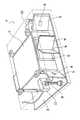
図1は、本発明の好適なローンチモニター装置10を例示する。斯かるローンチモニター装置10は、支持構造体12、クラブモニター14、ボールモニター16、マイクロプロセッサー18、コンピュータ20及びモニター22を含む。マイクロプロセッサー18及びコンピュータ20は、別体のユニットとして図示されているが、1つの要素に結合されても良い。同様に、コンピュータ20及びモニター22は別体のユニットとして図示されているが、1つの要素に結合されても良い。マイクロプロセッサー18及びコンピュータ20は、本装置において使用される幾つかのアルゴリズム及びプログラムを有して装置を制御すると共に、以下に説明する如く、諸々の判定を行う。
【0018】
図1及び図2を参照すると、支持構造体12は、後部フレーム24、下部フレームサブアセンブリ26、上部フレームアセンブリ28、下部ベース30、上部ベース32及びロッド34を含む。後部フレーム24は、隔置された2つの平行な水平フレーム部材35及び36及び隔置された2つの平行な垂直フレーム部材38及び40(図1に図示される如く)を含む。前記部材35乃至40は、一体に締め付けられて矩形を形成する。
【0019】
下部フレームサブアセンブリ26は、ブレース46及びファスナーでそれぞれ前記垂直フレーム部材38及び40に結合された2つのフレーム部材42及び44を含み、部材42及び44は、それぞれ、部材38及び40に対して略垂直方向に伸張するようにされる。下部フレームサブアセンブリ26は、更に、部材48を含み、該部材は、部材42及び44の間に伸長すると共に、ブレース50及びファスナーで部材42及び44に結合されて、部材48が部材42及び44から垂直方向に隔置されるようにされる。部材48は、その前面及び後面に溝48aを含む。
【0020】
上部フレームサブアセンブリ28は、隔置された2つの平行なフレーム部材52及び54及び隔置された2つの平行なフレーム部材56及び58(図1に図示する如く)を含む。これらの部材52乃至58は、一体に締め付けられて矩形を形成する。部材56及び58は、それぞれ、ブレース60、固定ファスナー及び関連付け可能なファスナー62で垂直部材38及び40に結合される。このように、上部フレームサブアセンブリ28は、回転をして水平平面Hともに自身の角度αを変更することができる。平面Hは地面Gに平行である。部材52及び54は、前面及び後面に溝52a及び54aを有する。
【0021】
説明はしないが図示したブレースをフレームの部材間で追加して使用してフレームが必要な構造上の堅牢性を有するようにすることが可能である。フレームは、モニター14及び16(図1に図示する如く)を必要な方向に支持すると共に、オペレータが所望通りに調節出来るのであれば異なる構成を有することが可能である。クランプをベース30及び32に結合して、該ベースを特定の位置に保持することができる。このフレームは、アルミニウム等の様々な材料から形成することができる。
【0022】
下部ベース30の後端は、溝48a及びスライド部材64を介してフレームの部材48に結合されて、ベース30が、部材48の長さ方向に沿って移動可能にされる。下部ベース30の前端は、図3に最も良く図示される如く、ロッド34と摺動自在に協働するパッド(図示なし)を有する。ロッド34は、分離自在のセグメントに形成されて、分解組立てが自由となるように、或いは、1本のロッドとして使用できるようにされる。
【0023】
上部ベース32は、支持部材68を含み、該支持部材上には、回動自在のホイール70が取り付けられる。支持部材68及びホイール70は、溝52a及び54aと協働するような構成及び寸法にされて、ベース32が、部材52及び54の長さ方向に沿って移動できるようにされる。
【0024】
図1を再度参照すると、クラブモニター14は、ベース32により画定された第1の水平平面H1と整列するように配置され、ボールモニター16は、ベース30により画定された第2の水平平面H2に整列するように配置されて、クラブモニター14が、距離ΔHだけ上方に隔置されるようにされる。モニター14及び16は、更に、クラブモニター14の中心C1が、ボールモニター16の中心C2から距離ΔCだけ隔置されるように位置決めされるのが好適である。この配置により、ローンチモニター装置が、下記に詳細に説明する如く、図5A及び図9に図示する如く、ゴルフクラブ71及びゴルフボール72の画像を捕捉するのが可能となる。
【0025】
図1を参照すると、クラブモニター14は、第1のクラブカメラCC1、隔置された第2のクラブカメラCC2、コントロールボックス73、4つの反射要素74、76、78、80、支持体84上の第1のクラブモーションセンサー82、及び支持体88上の第2のクラブモーションセンサー86を含む。
【0026】
前記使用されるカメラCC1及びCC2は、受光絞り、シャッター及び光感知シリコンパネルを供えた電気光学カメラである。CCDカメラが好適であるが、TVタイプのカメラも利用することができる。推奨できる市販のカメラは、3分の1インチの対角線CCDのXC55名でソニー社(Sony)により製造されるものである。
【0027】
図3及び図4を参照すると、それぞれのカメラCC1、CC2からのビデオライン89は、コントロールボックス73へ繋がる。コントロールボックス73は、ストロボユニット90及び該ストロボユニットの前に光学またはフレネル(Fresnel)レンズ92を含む。ストロボユニット90は、単一のフラッシュバルブアセンブリ、関連回路及び円筒状フラッシュ管を備える。ストロボユニット単一フラッシュバルブアセンブリは、1000マイクロ秒を超える速さで閃光を発することができる。ストロボユニットに使用される回路は、共有譲渡されたデイ氏(Day)の米国特許第6,011,359号の主題であり、該米国特許は、その全体を明確に引用するために本明細書に組み込んである。
【0028】
反射要素またはパネル74、76、78、80は、ベース32上に取り付けられる。反射パネル74、76は、また、反射絞り94、96を含み、カメラCC1及びCC2及びパネル74、76は、レンズ98、100(図4に図示する如く)が、反射パネル74、76の反射絞り94、96を通して指向されるように取り付けられる。第3及び第4の反射要素78及び80は、フレネルレンズ92の正面に配置される。パネル78は、フラッシュバルブユニット90からの光の約半分をパネル74内へ反射し、一方、パネル80は、前記光の残りの半分を光反射パネル76内へ反射する。或いは、各カメラレンズを囲繞する環状のストロボを使用して反射パネルを一切不要とすることができる。ゴブッシュ氏(Gobush)等の米国特許第5,575,719号に開示される如く、1つまたは2つのストロボを各カメラに隣接して使用すれば、前記パネルを排除することができ、該米国特許は、その全体を本明細書に組み込んである。パネル74、76、78、80は、アルミニウム、ステンレススチール、クロムメッキ金属または金メッキ金属等の研磨した金属から形成したパネルとすることも可能である。
【0029】
図1を再度参照すると、クラブカメラCC1及びCC2は、ケーブル102を介してマイクロプロセッサー18及びコンピュータ20に電気的に接続される。図示した第1のクラブモーションセンサー82及び第2のクラブモーションセンサー86は、トリトロニクス社(Tritronics)により製造される光電センサーである。センサー82及び86は、反射マウント104と一緒に使用される。該マウント104は、ベース106及び2つの円筒状ロッド108及び110を含む。円筒状ロッド108及び110は、カメラCC1及びCC2に面した側に反射材料からなるストリップを有する。第1のクラブモーションセンサー82からの光ビームは、ロッド108上の前記材料からセンサーに反射に向けて反射される。第2のクラブモーションセンサー84からの光は、ロッド110の前記材料からセンサーに向けて反射される。受光源として使用される光検出器等のその他のタイプのセンサーは、また、モニター14カメラCC1及びCC2を起動するのに使用することができる。
【0030】
クラブモニター14と同様にボールモニタ16は、第1のボールカメラBC1、隔置された第2のボールカメラBC2、コントロールボックス12、4つの反射要素114、116,118、120、ボールセンサー122を含む。
【0031】
使用されるカメラBC1及びBC2は、米国特許第5,575,719号に開示される如く受光絞り、シャッター、及び、光感知シリコンパネルを備えた電気光学カメラが好適であるが、TVタイプのカメラを使用することも可能である。推奨できる市販のカメラは、EDCカメラ名でエレクトロリム社(Electrim Corporation)により製造されるものである。
【0032】
コントロールボックス112及び4つの反射要素114、116、118、120は、クラブモニター14に関して説明したのと同様である。
【0033】
ボールモーションセンサー122は、マイクであり、モニター16の動作を開始するのに使用される。レーザーまたはその他の装置(図示なし)を使用してローンチモニター装置を起動することもできる。例えば、起動手段は、クラブモニター14と同様に、光ビーム及びセンサーを含むことが出来る。
【0034】
ボールカメラBC1及びBC2は、電気的に直接マイクロプロセッサー18に接続されると共に、コンピュータ20に間接的に接続される。マイクロプロセッサー18は、コンピュータ20に対してボールカメラをクリアして準備するように指示する。センサー122もマイクロプロセッサー18及びコンピュータ20に電気的に接続される。
【0035】
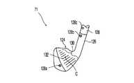
図5Aを参照すると、クラブ71は、ホーゼル126を備えたクラブヘッド124を含み、該ホーゼル126にシャフト128が取り付けられる。クラブ71には、更に、3つの隔置された丸い反射領域またはマーカー128a乃至cが配置されている。斯かるマーカー128aは、クラブヘッド124のトウに配置される。マーカー128bは、ホーゼル126の自由端に配置される。マーカー128cは、シャフト128上に配置される。マーカーは、3つであるのが好適であるが、最小2つであっても良い。本発明は、マーカーの数に関して、本明細書に開示した数に限定されるものではない。マーカーの位置は、当業者に公知の方法で変えることができる。例えば、クラブヘッドのトウに2つのマーカーを配置し、ホーゼルに1つのマーカーを配置することができるし、別のクラブヘッドでは、1つのマーカーをトウに配置して、ホーゼルに2つのマーカーを配置することができる。
【0036】
マーカー128a乃至cの径は、1インチの4分の1乃至8分の1であるのが好適であるが、その他のサイズ及び領域形状を使用することできる。マーカー128a乃至cは、好適には、クラブヘッド124、ホーゼル126及びシャフト128に接着した反射材料から形成される。ミネソタ・マイニング・アンド・マニファクチャリング社(Minesota Mining and Manufacturing)(3M)により製造される「スコッチライト(Scotchlite)」ブランドのビード材料がマーカーを形成するのに好適である。コーナー反射のリフレクターを使用することも可能である。或いは、塗装マーキング、スポットまたはラインを使用して少なくとも1つの対照領域を画定することができる。
【0037】
クラブヘッド124は、更に、表面に溝130を含む。溝132は、クラブヘッドのジオメトリ中心Cを貫通して配置されて、クラブヘッドのジオメトリ中心Cをマークすることが可能となる。
【0038】
図5Bを参照すると、ティーアップされたボール72は、同様のマーカー130a乃至fを有する。マーカー130fは、ボールの中央に配置され、マーカー130a乃至eは、その周りに配置される。非中央マーカー130a乃至e間の角度をβとする。角度βの推奨角度は、約10°乃至40℃である。最も好適には、角度βは、30℃である。逆反射(retro−reflective)マーカーよりは、寧ろ、コーナー反射材料または塗料を使用することができる。6つのマーカーを図示してあるが、代わりに1本の線、または、最小2個で最大11個のマーカーをボール上に使用することができる。
【0039】
図6を参照すると、以下に説明する如くクラブヘッド71を校正するには、クラブヘッド校正用取付具136を使用する。斯かる取付具136は、磁気ベース138を含み、該ベースは、中央に配置した貫通孔140を画定する。該ベース138に延長部142が接続される。該延長部の面144は、垂直配向ラインvと整列し、該延長部の切欠き146により、ベース138内の孔140が見えるようにされる。面144は、逆反射マーカー148a乃至cを含む。マーカー148a乃至bは、互いに整列し、マーカー148cは、前記マーカーからオフセットされる。
【0040】
図7を参照すると、モニター14及び16(図1に図示する如く)を下記の説明する如く校正するのにクラブモニター取付具150及びボールモニター取付具151を使用する。クラブモニター取付具150は、背壁152、該背壁152から伸長した中央壁または脚154、背壁152から伸長すると共に中央脚154から隔置された外側壁または脚156及び158を含む。中央脚154の背壁152表面からの長さは、背壁152表面からの外側脚156及び158の長さより短い。
【0041】
校正取付具150は、使用されるときには、カメラCC1及びCC2の視界内に位置決めされなければならない。距離校正具及びタブを取付具150と一緒に使用して、ゴブッシュ氏(Gobush)等の特許出願番号09/156,611号に開示される如く適切に位置決めがなされる。該特許出願はその全体を引用するために本命最初に組み入れてある。
【0042】
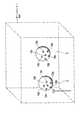
校正取付具150は、一定のパターンの対照領域または逆反射マーカー160a乃至uを有する。出願人等は、21個のマーカーが好適であることを判明した。校正取付具の垂直方向のマーカーの数を少なくすることが、ローンチモニター装置を十分に校正するの必要である。対照領域の数は、最小で6個であり且つ21個を超えることができる。領域160a乃至uは、背壁152、中央脚154の自由端、及び外側脚156及び158の自由端に配置されるので、マーカーは、3次元に配置される。しかしながら、マーカーは、また、2次元にのみ配置することも可能である。マーカーは、2次元または3次元の対照塗装領域に置き換えることができる。
【0043】
取付具150は、更に、光学レベルインジケーター及び取付具を水平にする脚部またはスパイクを含むことができる。
【0044】
ボール取付具151は、クラブ取付具150と同様の構成にされるが、ボールモニター16(図2に図示する如く)が、クラブモニター14より地面に近い場所を見るために、ボール取付具151は、クラブ取付具150より低くされる。さもなければ、ボール取付具151をクラブ取付具150と同様に構成すると共に、15個の逆反射マーカー160a乃至oを含む。対照領域の数は、最小で6個であり且つ15個を超えることができる。ボール取付具に対する斯かる修正は、クラブ取付具151に対して提案された修正と同様とすることができる。
【0045】
装置10(図1に図示する如く)の使用の概略を図8に図示する。ステップS101において、装置が始動して、斯かる装置の使用が初めてか否かを判定する。見落とされると、装置が最初に始動された時に、最後の校正を使用することになる。従って、装置は、作動及び/またはスイッチを入れる度に校正を行わなければならない。
【0046】
ステップS102では、オペレータが、クラブヘッド及び装置を校正する。校正後、ステップS103で装置をテストされるゴルファーに応じて左利きまたは右利き何れかの向きにセットする。左利き用の向きを選択すると、左利きゴルファー用の1組の座標を使用することが必要になり、右利き用の装置は、右利きゴルファー用の別の組の座標が必要となる。この時、装置は、テストまたはデモンストレーションのいずれかにセットされる。テストモードを選択した場合には、装置はテスト用データをセーブし、一方、デモンストレーションモードでは、テスト用データはセーブしない。
【0047】
ステップS103でテストの位置及びゴルファーに対する特定のデータも入力する。特に、オペレータは、ゴルフボールの飛行、転がり及び総距離の算出に使用される温度、湿度、風速及び風向、高度及び芝のタイプ等の周囲条件に関するデータを入力する。オペレータは、また、ゴルファーの個人データを入力する。この個人データは、名前、年齢、ハンディ、性、ゴルフボールのタイプ(下記に説明する弾道の計算に使用される)及び使用されるゴルフクラブを含み、ゴルフクラブに関するデータには、クラブヘッドのタイプ(アイアン、ドライバー、ウッド、ロフト、及びライ)及びシャフトの情報等の情報を含む。
【0048】
このデータが入力されると、装置は使用の準備が整い、ステップS104へと進む。ステップS104では、装置は、プレーヤーがバックスイングを行いクラブが移動すると、センサー82(図1に図示する如く)及びロッド106間のビームの中断が起きるのを待つ。センサーは、マイクロプロセッサー18に信号を送って、コンピュータにボールカメラBC1及びBC2を「作動状態にする」ように指示して、信号が送られて来たなら何時でもシャッターを切れる状態におくようにする。ボールカメラを作動状態にすることは、CCDカメラ内のパネルをクリアにして起動準備をすることを意味する。画像を撮る前にボールカメラを作動状態にするのは、特定のカメラBC1及びBC2を使用するからである。その他の作動状態に即座に入れるカメラを使用する場合には、このステップ及び追加のセンサー82は不要となる。信号は、また、マイクロプロセッサー18にも送られて、第2のスイングセンサー86からの信号に対する準備が整う。
【0049】
ダウンスイングと同時に、センサー86及びロッド108間のビームにより、クラブモニター14が光をセンサーパネルへ露光する。86からのビームに中断があると、クラブモニター14は、センサーパネルの同時露光中にストロボを2度焚いて、クラブヘッド71の位置AおよびB(図9に図示する如く)における2つの画像が1つのフレーム内に入るようにされる。十分なレベルの音がマイク122により拾われると、ボールモニター16(図1に図示する如く)がボール72(図10に図示する如く)の2つの画像を得る。図9のクラブ画像と図10のボール画像との間の時間量は、短く、800マイクロ秒であるのが好適である。画像は、下記に説明する如く、各々のカメラのシリコンパネルにより記録され、装置は斯かる画像を使用してクラブモーションデータ及びボールモーションデータの判定を行う。
【0050】
ステップS105乃至S107では、装置は、コンピュータに格納されてある幾つかのアルゴリズムを使用してモニターに対するゴルフボールの位置を判定する。コンピュータが画像からゴルフボールの位置を判定すると、装置(及びコンピュータアルゴリズム)は、ローンチの条件を判定する。これらの判定は、ステップS105、S106、及びS107に対応し、画像中の明るい領域の位置決め、それらの明るい領域のどれがゴルフクラブまたはボール上のマーカーに対応するかの判定、及び、次いで、この情報を使用して画像からクラブまたはボールの位置を判定するとともに、下記に説明する如く、データをそれぞれ算出する。特に、ステップS105で、装置は、カメラが記録した画像を画像中の明るい領域を位置決めして分析する。画像中の明るい領域は、ゴルフクラブまたはボール上の逆反射マーカーまたはマーカーで反射したフラッシュバルブアセンブリからの光に対応する。
【0051】
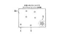
ゴルフクラブは、好適には、その上に3つのマーカーを有するから、装置は、2つのカメラの各々からの画像におけるクラブマーカーを表す6つの明るい領域を見つけ出さなければならない。図11は、カメラCC1が受けた画像を表し、図12は、モニタースクリーン22a上に表されたボールを叩く前のクラブヘッドのカメラCC2が受け取った画像を表す。次いで、ステップS106において、装置は、それらの明るい領域のどれがゴルフクラブの反射マーカーに対応するかを判定する。
【0052】
ボールは、該ボール上に6つのマーカーを有することから、装置は、カメラBC1及びBC2の各々からの画像のマーカー(ゴルフボールの2つの画像で6つのマーカー)を表す12個の明るい領域を見つけ出す。図13は、カメラBC1が受け取った画像を表し、且つ、図13は、モニタースクリーン22a上に示された叩いた後の該ボールのカメラBC2が受け取った画像を表す。次いで、装置は、ステップS106で、それらの明るい領域のどれがゴルフボールの反射マーカーに対応するかを判定する。下記に詳細に説明する如く、これは、幾つかの方法により達成できる。クラブについてはたった6つのマーカーしか画像中に見つけられなかった場合、または、ボールについてはたった12のマーカーしか見つけられなかった場合には、装置は、ステップS107へ進んで、画像中のマーカーから第1及び第2の画像の間のゴルフボールの位置及び向きを判定する。
【0053】
しかしながら、画像中に所望の数より多いまたは少ない数のマーカーまたは明るい領域が見つかった場合には、ステップS108において、オペレータは、装置により手動で画像を変更できるようになる。配置された明るい領域の数があまりにも少ない場合には、オペレータは、画像の輝度を調節し、前記数が余りに多い場合には、オペレータは任意の数の追加の明るい領域を消去する。ある例では、画像中の明るい領域はゴルフボールまたはゴルフクラブヘッドからの反射である場合がある。輝度の十分な調節や外部からの影響を受けて明るくなった領域を除去することが不可能な場合には、装置は、オペレータにステップS104へ戻ってゴルファーに別のボールを打つように指示する。前記領域の手動編集が成功した場合には、装置は、次に、ステップS107へ進む。
【0054】
ステップS107では、装置は、ステップS106におけるマーカーの識別を利用して2つの画像の各々の6つまたは12のマーカーの各々の中心に位置を判定する。マーカーの各々の中心の位置を知っていれば、装置は、ゴルフクラブの速度、ロフト角度、アタック角度、パス角度、フェース角度、ドループ角度、ロフトスピン、フェーススピン、ドループスピン、及びヒット位置を算出することができる。更に、装置は、ボールの速度、打ち上げ即ちローンチ角度、バックスピン、サイド角度、サイドスピン、ライフルスピン、飛距離、方向、飛距離及び転がり距離を合わせた距離を算出することができる。
【0055】
ステップS109では、装置は、上記の情報及びステップS103で入力された周囲条件及びゴルフボール情報を使用してショット中のゴルフボールの弾道を算出する。装置は、また、ゴルフボールの落下場所(飛距離)及びどれだけ遠くまで転がるかを推定して、当該ショットの総距離を提供する。装置は、3次元で校正されることから、装置は、また、ゴルフボールがスライスかフックか、及び、ボールがどれ位ラインから外れるかを算出することができる。
【0056】
この情報(即ち、ゴルファーのクラブ及びボールデータ)は、次いで、ステップS110において、数値及び/またはグラフィックの形態でゴルファーに提出される。ステップS111では、装置は、また、異なるゴルフボール(例えば、スリーピースゴルフボールよりは寧ろツーピースゴルフボール)が使用された場合には、同一の情報を算出することができる。また、ローンチ条件(ゴルフボール速度、スピン速度、及びローンチ角度)のいずれかが変動した場合の結果に与える影響を判定することが可能である。
【0057】
ゴルファーは、また、ステップS112以降で、装置をステップS104に戻してもっとショットを行うオプションも有する。プレーヤーが、ステップS103でテストモードを選択して、幾つかの異なるショットをした場合には、装置は、ステップS113でテスト中に累積された全てのデータの平均を算出して提示する。ステップS114で、装置により、ゴルファーに対して自身の特定の能力に対する理想的なローンチ条件が提示されて、プレーヤーが変更を行って距離を最大限にすることが可能となる。装置により、ゴルファーは、例えばステップS115で、新たなゴルフクラブを使用して新たなテストを開始することができ、または、S116で斯かるセッションを終了することが出来る。
【0058】
図15に詳細に表した校正ステップS102(図8に図示した如く)へ戻ると、校正は、クラブヘッドの校正で始まる。図5A及び図6を参照すると、ステップ201の如く、プレーヤーは、クラブヘッド71を選択する。次いで、ステップ202において、オペレータは、中央の溝132を利用してクラブヘッドのジオメトリ中心またはスィートスポットにマークを付ける。図6及び図15を参照すると、ステップS203において、オペレータは、校正取付具136をクラブヘッドのフェースに取り付けて、ジオメトリ中心Cがベース138の孔140の中心に来るようにする。ステップS204及びS205で述べる如く、次いで、クラブヘッド71は、クラブモニター14の視界内にセットされると共に、カメラCC1及びCC2によりクラブヘッド及び取付具の1つの画像が得られるまで動かないように保持される。画像は、モニター14からの光がマーカー148a乃至cにより反射するために対照領域を含む。マイクロプロセッサー18がカメラフラッシュのタイミングを制御する。ステップS206において、コンピュータ20の変形アルゴリズム(複数のアルゴリズム)でクラブヘッド上の点とクラブヘッドの基準点またはジオメトリ中心と相関させる。取付具136の詳細は、ゴブッシュ等の米国特許第5,575,719号に開示されており、該米国特許は、その全体を引用するために本明細書に組み込んでいる。
【0059】
図1及び図8を参照すると、取付具136を使用した後の校正ステップS102は、更に、モニター14及び16の校正を含む。このステップの詳細は、図16に詳細に例示する。最初に、ステップS301において、装置10をセットして水平にする。装置10は、好適には水平な地面にセットされるのが好適であり、例えば、練習用ティーまたは水平な広い場所である。また、室内でネットに向けてボールを打つテストも可能であるのは明らかである。装置は、イベントが最も良く見えると共に、所定の視界にセットされるように位置決めされる。次いで、ステップS302において、校正取付具150及び151(図7に図示する如く)をそれぞれモニター14及び16の視界内の適切な場所に配置する。この適切な場所とは、取付具150からカメラCC1及びCC2までの距離が約101.6cm(約40インチ)であり、取付具151からカメラBC1及びBC2までの距離が約76.2cm(約30インチ)である。好適には、校正取付具150及び151は、水平且つ装置に対して平行となって、モニター内のフラッシュバルブアセンブリからの光の反射が確実に最良のものとなるようにする。各モニター14及び16の双方のカメラCC1及びCC2及びBC1及びBC2は、それぞれ、ステップS303において、各校正取付具の写真を撮り、画像をバッファへ送信する。
【0060】
ステップS304では、装置は、校正アルゴリズムを使用して、各校正取付具の逆反射マーカー160a乃至u及び162a乃至oに対応する各画像のスポットの中心の位置を判定する。
【0061】
校正取付具150上のマーカーの真のスペースを装置に入力しておかねばならない。クラブ取付具150及びモニター14についてこの判定を行うためには、取付具150上の事前に測定した点及び各カメラのセンサーパネル上にディジタル化された21のU及びV座標が与えられれば、11の定数が、焦点の長さ、各カメラCC1及びCC2の向き及び位置を判定する。
【0062】
各カメラCC1及びCC2のセンサーパネルは、480のラインのデータ及び1ラインにつき640画素を含んだ連続した光のパターンを受け取る。一定のコンピュータアルゴリズムを使用して各マーカー160a乃至uの図心を検出する。マーカーの図心検出は、マーカーの中央領域の位置決めをして精度及び解像度を上げるためのものである。マーカー160a乃至uから受信した各画像は、明らかに各マーカーのx及びyの中心位置である。ゲートのために視界内の光が少ない場合には、画像高輝度表示装置をセンサーパネルと関連して使用することが可能である。画像高輝度表示装置は、入力画像より明るい出力画像を生成する装置である。
【0063】
各マーカー160a乃至uのX、Y及びZ座標は3次元パターンに配列されており、ディジタル化テーブル上で10000分の1インチの精度まで事前に測定して、コンピュータに格納した。校正取付具150の画像は、2つのカメラCC1及びCC2で得る。
【0064】
この画像は、画像スペース座標U及びVを校正取付具150上の公知の21のX、Y及びZ位置と関連させる11の定数を判定する。校正されたX(i)、Y(i)、Z(i)の隔置された点をUi(j)、Vi(j)の画像点と関連させる式は、下記の通りである。
カメラCC1に対する11の定数Di1(i=1,11)及びカメラCC2に対する11の定数Di2(i=1,11)は、21の場所X(i)、Y(i)、Z(i)及び2つのカメラの校正写真において測定した21のUi(j)、Vi(j)座標が分かれば解くことができる。
【0066】
21のマーカーを備えた校正取付具の右利き用校正のための上記の3次元位置の代表的な組は下記の通りである。
21のマーカーを備えた校正取付具の左利き用校正のための上記の3次元位置の代表的な組は下記の通りである。
装置は、所定の閾値より大きな光輝度を有したバッファの画素の位置を識別することでボール取付具151からスポットの中心を位置決めする。画像は、2次元であることから、画素の位置は、2つの成分(x、y)を有する。装置は、画像を探索して明るい領域を見つけ出し且つ明るい領域の各々の縁を見つけ出す。次いで、装置は、明るい領域の各々の中心を大まかに推定する。次いで、明るい領域の各々の明るい画素の全ての平均を出して、正確なマーカー位置及びサイズをボール取付具から15の全ての領域について算出する。最小領域より小さな領域のものは無視する。カメラBC1及びBC2に対する校正取付具151上のマーカーの各々の位置が一旦判定されると、装置は、校正取付具151上のマーカー間の真のスペースがわからなければならない。ボール取付具151及びモニター16に関してこの判定を行うためには、校正取付具が3行5列に平均したマーカーを有する。マーカーは、約2.54cm(約1インチ)離すと共に、約3.81cm(1.5インチ)離れた3つの別個のX平面上に配置される。各マーカー170a乃至oの中心のX、Y及びZ座標は、3次元パターンに配列され、ディジタル化テーブル上で10000分の1インチの精度まで事前に測定して、コンピュータに格納した。装置は、校正取付具上のマーカーの互いの3次元位置に関する先に格納したデータを呼び出す。呼び出されるデータは、右利き用(ゴルファーに向うX軸の点)または左利き(ゴルファーから離れるX軸の点)装置を使用するのかにより決定される。双方の組のデータは格納されて、ステップS305においてオペレータにより選択することができる。15のマーカーを備えた校正取付具の右利き用校正のこれらの3次元の位置の代表的な組は、下記の如くとなる。
ステップS306では、校正取付具151の画像を利用して、装置は、画像スペース座標U及びVを校正取付具上の公知の15のX、Y及びZ位置と関連させる11の定数を判定する。校正されたX(I)、Y(I)、Z(I)の隔置された点をUij、Vijの画像点と関連させる式は、下記の通りである。
カメラ136に対する11の定数Di1(i=1,11)及びカメラ138に対する11の定数Di2(i=1,11)は、15の場所X(I)、Y(I)、Z(I)及び2つのカメラの校正写真において測定した15のUij、Vijの座標が分かれば解くことができる。
【0071】
別の実施例では、画像分析中に、装置は、標準のランレングス符号化(RLE)技術を利用して明るい領域を位置決めする。RLE技術は、従来の技術であり、当業者には公知のものである。画像分析は、校正中または実際のショット中に行うことが出来る。RLE技術を利用して一旦明るい領域が位置決めされると、次いで、装置は、画像中の全ての明るい領域のアスペクト比を算出して、前記領域のどれが逆反射マーカーであるのかを判定する。どの明るい領域がマーカーであるかを判定する技術は、図17を参照して詳細に説明する。
【0072】
上記した如く、ステップS102において、一旦装置が校正されると、オペレータが、温度、湿度、風、高度、及び芝の状態を含んだ周囲条件を入力することができる。次に、オペレータは、ゴルファーについての入力を行う。例えば、オペレータは、ゴルファーの名前、テスト場所、性、年齢及びゴルファーのハンディを含んだゴルファーに関する情報を入力する。オペレータは、また、各テスト毎に、ゴルフボールのタイプ及びシャフト情報を含んだクラブのタイプを識別する。オペレータは、また、操作モード(即ち、クラブ及びボールデータの入手か、クラブのみのデータの入手か、または、ボールのみのデータの入手か)、マイク感度、ボールカメラセンサーの調節、クラブ及びボールのストロボ照射画像間の例えばマイクロ秒での遅延時間等の様々なハードウェアの設定パラメータを入力することができる。特定のメーカーのボールカメラでは、カメラセンサーのソフトウェア調整が可能であるが、選択したクラブカメラは斯かる特徴を有しない。別のクラブカメラであれば前記特徴を有する場合がある。オペレータは、また、どこにデータを格納するのか及びデータの説明等の様々なテストセットアップ用のパラメータを入力することができる。また、オペレータは、各軸線に沿ったクラブ及びボールカメラの精度等の装置校正変数を入力することができる。
【0073】
校正が完了し且つ図1乃至図9を参照すると、ゴルフボール72が校正取付具が配置された(カメラCC1及びCC2から約101.6cm(約40インチ)に)ティーの上に設定され、クラブ71がアドレスにおいてボール72の背後に配置され、シャフト128のクラブヘッド126が、3次元クラブモニター14の視界内で振られる。ボールを叩く約15.24cm(約6インチ)前でセンサー86及びロッド110間で光ビームが中断されて、CC1カメラ及びCC2カメラのシャッターを開けて、CC1カメラ及びCC2カメラ内の画像センサーパネルが、3つのクラブ71マーカー128a乃至c及び6つの静止ボールマーカー134a乃至fからの光に露出される。この照射はクラブ71が位置Aにあるときに起きる。所定の時間後に、例えば、800マイクロ秒後に、フラッシュライトユニット90(図4に図示の如く)が閃光を発して、該閃光がクラブ71マーカー128a乃至c及び6つの静止ボールマーカー134a乃至fをサイド照射する。クラブ71が位置Bにあるときに上記が起きる。装置が使用できる閃光は、2つのみであるが、加速度データを必要とする場合には、ストロボが連続して少なくとも3度脈動してクラブの画像が3つ得られるようにされるのがより好適である。其の結果、加速度データを2つの速度測定から得ることができる。
【0074】
閃光の期間は1万から2乃至3百万分の1秒の間である。カメラCC1及びCC2では非常に小さな絞りが使用されて周囲の光を低減すると共に、ストロボの光を増大するようにされる。2つ位置において光がマーカー128a乃至cで反射されると、光は、センサーパネルに到達して、ディジタル化され且つコンピュータのモニター22スクリーン22a上で目視可能な対応するパネル領域を形成する。スクリーン上のマーカー128a乃至cからの画像は、図11及び図12では、マーカー128a’乃至c’として図示される。
【0075】
カメラ動作と該カメラ間のジオメトリ関係との間の公知の時間を使用して、外部の計算回路により各スナップショット時の共通の座標系における各増強したマーカーのX、Y及びZ位置を算出することができる。位置情報及び公知のデータから、前記外部計算回路は、叩く前のボール72のローンチ直前の時間における3次元のクラブヘッド速度及びスピン(または回転)を計算することができ、前記ローンチ直前のボールを叩く前の状態は、クラブヘッド位置A及びBに関するデータ及び位置Bからの静止したボール72の公知の位置からのデータに基づいた計算により判定される。また、パス方向、アタック角度、及びヒット位置は、クラブ71上の3つの反射マーカー128a乃至cにより提供される位置B情報から計算することができる。
【0076】
ゴルファーがクラブモニターの視界を通してクラブ71を振ると、装置の電子画像が、図11および図12に図示するごとく、カメラCC1およびCC2を介して見られる。カメラCC1の右側視界(図11の)は、カメラの向きが20度異なることから、カメラCC2の左側視界と若干異なる。3つのクラブマーカー、i、及び2つのカメラ、j、に対するカメラ座標をUi(j)、Vi(j)とすれば、解くべき式は以下の通りである。
位置Aにおけるクラブ71の公知の座標X(i)、Y(i)、Z(i)i=1,3により、コンピュータ20は、更に、図9の第2の位置BにおけるX(i)、Y(i)、Z(i),i=1,3の位置を分析する。また、電子画像は、ゴルフボール72上の6つのマーカー134a乃至fの位置を含む。カメラCC1、CC2のデータからの三角測量により、ボールの表面上の6つのマーカー134a乃至fに関する情報で、ボール72の中心Xc、Yc、Zcは、6つの式を解くことで算出される。
公知のクラブ71上のマーカー128a乃至cの位置情報により、クラブフェースC(Cx、Cy、Cz)の中心位置及びその局所座標系が、前に説明しクラブ校正手順によりボール72と叩く前の2つのストロボ位置A及びBにおいて見出される。次いで、座標系の3つの軸に沿ったクラブ71の中心の速度成分が以下の式から算出される。
【0079】
クラブヘッドスピン成分は、1つの向きのクラブヘッド126上のマーカー128a乃至cの向きを第2の向きのクラブヘッド126上のマーカー128a乃至cの向きに関係つける方向コサインのマトリックスから生じる。このマトリックスを要素Aij(i=1,3、j=1,3)を備えたAで表すと、時間増分ΔT間の2つのクラブヘッドの向きの回転ベクトルの角度の大きさθは、以下により与えられる。
スピン速度の3つの直角成分Wx、Wy、Wzは、以下により与えられる。
ボール72の中心とクラブ71フェースの中心Cとの間の距離からボール72の半径及びクラブフェースの中心の速度を引く計算からクラブフェースの最終位置がボール72の表面に接触するまでの時間を算出する。この時間が分かると、ボール72を叩く時にフェースが位置Cに到達するまでのフェースの速度は一定であると仮定して、3つのクラブヘッド126マーカー128a乃至cの位置を算出することができる。ボールを叩く時のこれらのクラブフェース位置を算出すうことで、クラブフェースの中心に対するボール72の位置を、ボール72の中心を通る線と前記3つの外挿したクラブ位置128a乃至cを使用して見つけたクラブフェース平面に対する法線との交点を見出すことで算出することができる。
【0082】
パス角度及びアタック角度は、フェースの中心で測定した速度成分(Vx、Vy、Vz)から見出される。パス角度及びアタック角度は、以下の如く画定される。
【0083】
例
上記の校正の後で、ゴルファーがアイアンを視界を通して振ってボール72を打った。以下のデータを得た。
表1の情報に基づくと、ゴルファーへのアドバイスは、ゴルフクラブをもっと速く振り、且つ、ボール叩く直前にゴルフクラブフェースを閉じるようにすることである。
【0085】
オペレータが得ることができて有効な追加のデータは、位置Bにおけるボールからのクラブヘッドの距離である。この距離がゼロまたはゼロ未満である場合には、クラブヘッドが位置Bにおいてボールに接触したことを意味し、従って、測定値は実際の速度を反映しておらず、取り直しとなる。
【0086】
図1及び図10を参照すると、クラブヘッドを振ってボールを叩くと、マイク122を介してゴルフボールを打つクラブからの音声トリガーが装置へ送信されて、ボールモニター16が起動される。ボールモニター14内のストロボユニットが起動されて、第1の画像が図10の位置Dにおいて双方のカメラBC1、BC2により記録される。ストロボが再度閃光して、位置DにおいてカメラBC1及びBC2が第2の画像を捉える前に800マイクロ秒であるのが好適な介入所定時間遅れが発生する。スクリーン上のマーカー128a乃至cからの画像は、図13及び図14において、マーカー134a’乃至f’として図示される。
【0087】
斯かる時間遅延は、一方の側においては、ストロボを閃光させる能力により制限されると共に、他方の側においては、視界により制限される。時間遅延が長すぎると、視界は、カメラの視界においてゴルフボールの2つの画像を捕らえるのに十分広くならない場合がある。装置10及び100において使用されるカメラは、2つの画像(第1及び第2のストロボ閃光時に生じる)が1つの画像フレームに記録するのを可能にする。ストロボが閃光する時に(ゴルフボール上の逆反射材料からの反射により)前記画像が記録されることから、閃光は、機械的にシャッターが切られるカメラの制限に関する心配をせずに必要なだけ一体に接近させることができる。
【0088】
この順番によりカメラの各光感知パネル上の逆反射マーカーからの反射光から画像が生成されて、図13のカメラBC1及び図14のカメラBC2からモニターに表示される。画像の各々のマーカーの位置は、好適には、校正取付具に関して前に説明したRLE技術により判定される。
【0089】
どの明るい領域がマーカーであるのかを判定するアスペクト比を判定するのに使用する技術を図17に関連して説明する。ステップS401に図示する如く、画像には適切に選択した明るさ閾値レベルがなければならない。画像の正しい閾値レベルを所定のレベルに設定することで、画像中の全ての画素が黒または白で表示される。第二には、ステップS402に於いて、画像を、画像の各々の明るい領域に対応して、はっきりと区別のつくセグメントに区分することである。ステップS403において、装置は、最初に以下の式を使用して前記セグメントの各々において以下の総和を算出して各領域の中心を判定する。
【0090】
ステップS404では、装置は、画像中の所定の範囲外の領域となる明るい領域を除去する。従って、大きすぎたり小さすぎる領域は除去される。好適な実施例では、ゴルフボール上のマーカーは、0.635cm乃至0.3175cm(4分の1インチ乃至8分の1インチ)であり、カメラは、753×244の画素を有し、画像中のマーカーは、約105画素から成る領域を有することとなる。しかしながら、正反射によるグレアは、クラブヘッド及びその他の物体からの反射を含み、画像の各々に追加の明るい領域が現れるようにする場合がある。従って、前記領域が、105画素より大幅に少ないか、または、大幅に多くなる場合には、装置は、それらの領域がゴルフボール上でマーカーとなり得ないことから、斯かる領域を無視することができる。
【0091】
残存する(即ち、画素が約105ある)領域に対しては、装置は、以下の方法によりどれが正しい12個なのかを判定する。装置は、マーカーが丸いという事実及びストロボが点灯する時間中におけるゴルフボールの動きからマーカーは、画像中に楕円形の形状を残すであろうと仮定する。従って、ステップS405では、次に、装置は、以下の式を使用して各領域の主たる慣性モーメントを算出する。
【0092】
図15に戻ると、マーカーの位置が一旦判定されると、装置は、ゴルフボールの中心の移動速度及びゴルフボールの角速度を以下の方法でステップS107にて算出する。先ず、装置は、カメラのデータからの三角測量を用いてゴルフボール表面の6つのマーカーの位置を位置決めする。特に、装置は、下記に示す4つの一次方程式を解いてゴルフボールの表面上の各マーカーのゴルフボールの座標系における位置(x、y、z)を判定する。
【0093】
次に、装置は、ゴルフボール座標系のマーカー位置(図16のステップS306において判定された)を以下のマトリックス式を使用して校正したカメラBC1、BC2の基準大域系へ変換する。
【0094】
大域座標系における移動速度の3つ成分及び角速度における3つの成分である運動学的変数は、質量中心の相対移動及びゴルフボールが2つの画像位置で成す相対回転角度から算出される。
【0095】
大域座標系の3つ軸に沿った質量中心の速度成分Vx、Vy、Vzは、以下の式より与えられる。
【0096】
大域軸系におけるスピン速度成分は、逆向きマトリックスMT(t)及びM(t+ΔT)の積を得た結果として生じる。結果とし生じた相対的な向きマトリックスA、A(t、t+ΔT)=M(t+ΔT)MT(t)は、2つのストロボによるゴルフボール画像の角度差を測定する。
【0097】
時間増分ΔT間におけるスピン軸線周りの回転角度の大きさθは、式11により与えられる。スピン速度の3つの直交成分Wx、Wy、Wzは、式12乃至14により与えられる。
【0098】
図15のステップS109において、コンピュータアルゴリズムを含んだ装置は、次いで、ステップS107で算出した初速度及び初期スピン速度を使用してテストの弾道を算出する。各時間増分に対して、装置は時間Tにおけるゴルフボール上の力を補間して、ゴルフボールの速度及び時間Tにおけるボールの力から時間T+1における速度を算出する。次に、装置は、平均速度及びレイノルズ(Reynolds)数を算出する。このレイノルズ数は、時間Tから時間T+1までの時間間隔における流れの慣性力と流れの粘力との比である。次いで、装置は、平均の力を補間し、それから時間T+1における速度を算出する。前記力は、抵抗力、ゴルフボールのスピンによる揚力及び重力を含む。時間T+1の速度を使用して、装置は時間T+1の位置を算出することができる。最後に、装置は、時間T+1のスピン速度を算出する。好適な実施例では、時間間隔の長さは、0.1秒である。この計算は、ゴルフボールが着地するまで続けられる。
【0099】
装置は、米国特許出願第09/156,611号の式を使用して上記の計算を行う。従って、装置は、ティーからゴルフボールの最終静止位置までの総距離を算出する。データファイルに弾道法により算出した結果を格納する。
【0100】
図15を参照すると、次いで、装置は、追加のテストを実施するか否かを判定する。追加のテストを行う場合には、上記に説明した工程即ち、ステップS104で音声トリガーによる起動から始まりステップS110の弾道法によりゴルフボールの弾道を算出して提示するまでの工程を繰り返す。
【0101】
全てのテストを実施し終えると、分析方法によりテストで使用した各ゴルフボールのタイプ毎に統計量を計算して、其の結果をオペレータに提示する。各ゴルフボールのタイプ毎に実施された1グループのテストに対して、装置は、速度、ローンチ角度、サイド角度、バックスピン、サイドスピン、飛距離と転がりを合わせて距離を含んだ幾つかのローンチ特性の平均から平均値及び標準偏差を算出する。
【0102】
異なる係数は、ゴルフボールの圧縮及びレジリエンスの変動、ゴルフボール上のマーカーの位置の変動、光感知パネルの画素解像度、及び校正取付具上の事前に測定したマーカーの精度を含んだ測定値の標準偏差に寄与する。ばらつきの主たる源は、典型的なゴルファーではスイング変動である。
【0103】
オペレータが要求すれば、装置は、様々な形態でテスト結果を表示する。例えば、装置は、オペレータの選択したゴルフボールのタイプに対する個々の結果を表示する。下記の表は、表1のクラブヘッドデータと得たのと同じスイング中に得たサンプルデータを示す。
表2の情報に基づいて、ゴルファーには、ゴルフボールを叩く時にクラブフェースをもっと閉じてスライスを無くすようにすること、及び内側から外側へスイングを修正してプッシュを無くすようアドバイスができる。
【0105】
同様に、ステップS113において、装置は、また、オペレータが選択したゴルフボールのタイプに対する弾道を表に提示して表示することができる。表の形式にして、距離、高さ、速度、スピン、揚力、抵抗、及びレイノルズ数を含んだ弾道情報を提示することができる。同様に、前記分析方法では、オペレータが選択したゴルフボールのタイプに対する弾道をグラフィックにして表示できる。装置は、各ゴルフボールのタイプ毎に算出した平均ローンチ条件からグラフィック弾道を算出する。
【0106】
ステップS113において、装置は、ゴルファーの行ったショットの各々の平均を表示する。結果は、表及び/またはグラフィックの形式で表示される。表示された結果は、総距離、スピン速度、ローンチ角度、飛距離、及びゴルフボール速度を含む。ゴルフボールのローンチ角度及びスピン速度に若干の変動があった場合には、装置は、ステップS114においてこの情報からゴルファーに結果を示して、ゴルファーが装置及び/またはスイングを最適化するのを可能にする。クラブ速度及び角度の変化に基づいて結果も変更されて表示される。
【0107】
ステップS114で、装置は、ゴルファーのローンチ角度及びスピン速度に近い様々なローンチ角度及びスピン速度で打たれたゴルフボールの距離を算出する。オペレータは、距離の算出に使用されるローンチ角度及びスピン速度を選択することができる。この特定のデータを表示するために、装置は、上記に説明した弾道計算を約50乃至100回(幾つかの所定値のローンチ角度及び幾つかの所定値の初期スピン速度)行う。オペレータは、装置が使用すべき一定の範囲のローンチ角度及びスピン速度、並びに、計算において装置が各々いくつの値を使用するのかを予測することができる。グラフィックデータ(*)から、ゴルファーは、前記2つの変数のどちらを変更して距離を改善するかを判定することが出来る。
【0108】
ゴルファーデータはセーブされるので、装置がテストモードの時には、その他のゴルファーのデータと当該ゴルファーのデータと比較することが可能であり、比較対照と成るその他のゴルファーのデータもセーブすることができる。このように、ゴルファーが、自身のデータ(ローンチ角度、ゴルフボールの初速度、スピン速度等)とその他のゴルファーのデータと比較することが可能となる。この比較には、表またはグラフィック形式で行うことが可能である。同様に、装置は、連続したクラブ(例えば、5番アイアン、6番アイアン、7番アイアン)のデータを比較して、クラブの順番に飛び越し(クラブの各々間の一定でない距離)があるか否かを判定する。或いは、2人の異なるゴルファーを、同一または異なるクラブ、または同一または異なるゴルフボールを使用して比較することができる。
【0109】
クラブカメラは、ボールカメラのフィルターとは異なるカラーのフィルターを含むことができる。例えば、クラブカメラは、異なるカラーのフィルターを含むことが出来、クラブ及びボールは、異なる色のマーカーを含むことが出来る。正味効果は、クラブカメラでクラブ上のマーカーの画像を記録し、ボールカメラで、クラブではなくボール上のマーカーの画像のみを記録するこである。異なるカラーフィルター及びマーカーの使用に対する代替策として、クラブ上に輝度の低いマーカーを使用すると共に、クラブモニターに光度の高いストロボを使用することができるし、明るいマーカーをボール上に使用して、弱い光度のストロボをボールモニタに使用することが可能である。これらによる正味結果は、カラーのついたフィルタ及びボール(即ち、クラブ画像は、クラブ及びボールマーカーを含み、ボール画像は、ボールマーカーのみを有する)を使用したのと同一の結果となる。
【0110】
上記発明を一定の好適な実施例を参照して説明してきたが、本発明の範囲は、それらの実施例に限定されるものではない。本装置は、バックスイング中のゴルファーのスイング、ダウンスイング中のゴルファーのスイング及び/または双方のスイングを測定するようにセットすることができる。本装置は、2台のクラブカメラ及び2台のボールカメラを備えるように図示されているが、1台のクラブカメラ及び1台のボールカメラを使用することが可能であるが、カメラがたった2台であることから測定の精度は落ちる。1つのクラブ及びボールカメラからなる装置を上記のライト配列のいずれかと一緒に、例えば、2つの隣接したストロボ等と一緒に使用することが出来る。上記の実施例は、また、修正が可能であり、1実施例のある特徴を別の実施例の特徴と共に使用することが出来るようにすることが可能である。当業者であれば、本発明の趣旨及び以下に記載する特許請求の範囲に規定される範囲を逸脱しない範囲での修正を見出すことは可能である。
【0111】
【発明の効果】
本発明の装置によれば、クラブは、少なくとも2つの対照領域を含むと共に、ボールは、少なくとも1つの対照領域を含み、前記クラブ画像は、少なくとも前記クラブの対照領域の全てを含み、前記ボール画像は、少なくとも前記ボールの対照領域の全てを含む。
【0112】
本発明の方法によれば、クラブ画像は、クラブがボールを叩く前に得られ、ボール画像は、クラブがボールを叩いた後で得られる。
【図面の簡単な説明】
【図1】クラブモニター及びボールモニターを含んだ本発明のローンチモニター装置の1実施例の斜視図である。
【図2】図1のローンチモニター装置の拡大側面斜視図である。
【図3】図1のボールモニターの拡大斜視図である。
【図4】図3のボールモニターの拡大頂面図である。
【図5A】クラブ校正取付具を取り付ける前のクラブヘッドの拡大斜視図である。
【図5B】ティーアップされたボールの拡大斜視図である。
【図6】クラブ校正取付具を取り付けた後の図5Aのクラブヘッドの拡大斜視図である。
【図7】図1に図示したクラブモニターと一緒に使用するクラブモニター取付具及び図1に図示したボールモニターと一緒に使用するボールモニター取付具の正面図である。
【図8】装置の動作を説明したフローチャートである。
【図9】クラブモニターの3次元視界中を移動するゴルフクラブを図示すると共に、測定位置A、測定位置B及び投影したインパクト位置を図示したクラブモニターの3次元視界の斜視図である。
【図10】ボールモニターの3次元視界中を移動するゴルフボールを図示すると共に、測定位置D及び測定位置Eを図示したボールモニターの3次元視界の斜視図である。
【図11】クラブモニターの第1のクラブカメラで得られた画像を図示したモニタースクリーンの正面図である。
【図12】クラブモニターの第2のクラブカメラで得られた画像を図示したモニタースクリーンの正面図である。
【図13】ボールモニターの第1のボールカメラで得られた画像を図示したモニタースクリーンの正面図である。
【図14】ボールモニターの第2のボールカメラで得られた画像を図示したモニタースクリーンの正面図である。
【図15】クラブヘッドの校正を説明したフローチャートである。
【図16】クラブモニター及びボールモニターの校正を説明したフローチャートである。
【図17】画像中のマーカーの判定を説明したフローチャートである。[0001]
BACKGROUND OF THE INVENTION
The present invention relates to a sports object, and more particularly, to an improved launch monitoring apparatus that analyzes two sports objects when a club is swung, that is, a launch monitor apparatus and a method of using the same.
[0002]
[Prior art]
Athletes, especially golfers, are interested in improving the performance of the game. One of the factors relating to the implementation of a golf game is the flight distance and the direction accuracy after hitting the ball. A golf ball manufacturer or the like can very accurately estimate the falling point of the hit golf ball from the values related to the ball speed, the flight direction, and the spin of the ball immediately after hitting. Further, a manufacturer or the like can diagnose a problem related to a golfer's swing if the speed, direction, and rotational movement of the golf club head immediately before hitting the ball are known.
[0003]
Devices are known that can be used to provide the above necessary data that can be used to determine the position of multiple points on a moving object at two close times and to estimate the above implementation factors. . These devices have problems with at least portability and / or accuracy.
[0004]
[Problems to be solved by the invention]
However, there is a need for a portable, easy-to-use, accurate and outdoor use launch monitoring device that can capture data relating to club movement and ball movement during a single swing of the club. .
[0005]
[Means for Solving the Problems]
A launch monitor device for measuring data relating to a club and a ball moving within a predetermined field of view includes at least one club camera, at least one ball camera, and a computer. Such a club camera and a ball camera are directed to a predetermined field of view. The club camera is positioned in a first plane, and the ball camera is positioned in a second plane that is spaced from the first plane in a vertical manner. Each club camera obtains at least two club images within a predetermined field of view. Each ball camera obtains at least two ball images within a predetermined field of view. The computer determines data relating to club movement or club motion from the club image and data relating to ball movement or ball motion from the ball image.
[0006]
DETAILED DESCRIPTION OF THE INVENTION
In general, the present invention comprises a launch monitor device that analyzes two separate sports objects, such as golf clubs and golf balls, while swinging the club, and methods of use thereof.
[0007]
According to one embodiment of the present invention, a launch monitor device for measuring data relating to a club and a ball moving within a predetermined field of view includes at least one club camera, at least one ball camera, and a computer. Such a club camera and a ball camera are directed to a predetermined field of view. The club camera is positioned in a first plane, and the ball camera is positioned in a second plane that is spaced from the first plane in a vertical manner. Each club camera obtains at least two club images within a predetermined field of view. Each ball camera obtains at least two ball images within a predetermined field of view. The computer determines data relating to club movement or club motion from the club image and data relating to ball movement or ball motion from the ball image.
[0008]
In one embodiment, the apparatus further includes at least two club cameras and at least two ball cameras. In another embodiment, the apparatus further includes at least one strobe associated with each of the club camera and ball camera.
[0009]
According to one aspect of the present invention, the club motion and ball motion data is at least two-dimensional, and preferably three-dimensional.
[0010]
According to another embodiment of the present invention, the apparatus includes a club camera and a ball camera directed to a predetermined field of view, and a computer. The club camera and the ball camera are arranged on the same side as the club and the ball. The computer determines data relating to club motion from the club image and data relating to ball motion from the ball image.
[0011]
According to one feature of the above embodiment, the club includes at least two control areas, the ball includes at least one control area, and the club image includes at least all of the control areas of the club; The ball image includes at least all of the control area of the ball.
[0012]
In accordance with the method of the present invention, such a method comprises the steps of a golfer swinging a club and hitting a ball, obtaining at least two club images at two different points in the swing, and during the swing. Obtaining at least two ball images at two different points in time, determining data relating to club motion from the club image, and determining data relating to ball motion from the ball image.
[0013]
Preferably, the club image is obtained before the club hits the ball, and the ball image is obtained after the club hits the ball.
[0014]
In this method, the step of determining data relating to club motion determines at least one of speed, acceleration, loft angle, attack angle, pass angle, face angle, droop angle, loft spin, face spin, droop spin, and hit position. Including doing. In this method, the step of determining the data relating to the ball motion includes the speed, launch or launch angle, back spin, side angle, side spin, rifle spin, flight distance, direction, and the distance that combines the flight distance and the rolling distance. Determining at least one of the following.
[0015]
In the method, an image of the club can be obtained in a downswing, a backswing, or both a downswing and a backswing.
[0016]
Preferably, the resulting club data and ball data can be used for individual players or groups of players in a swing-based club design and used to meet club specifications. And can be used to optimize the ecodynamics of a player or group of players.
[0017]
【Example】
FIG. 1 illustrates a preferred
[0018]
With reference to FIGS. 1 and 2, the support structure 12 includes a rear frame 24, a lower frame subassembly 26, an
[0019]
The lower frame subassembly 26 includes two frame members 42 and 44 coupled to the
[0020]
The
[0021]
Although not described, the illustrated brace can be added between the members of the frame to provide the necessary structural robustness to the frame. The frame can have different configurations as long as it supports the
[0022]
The rear end of the lower base 30 is coupled to the frame member 48 via a groove 48 a and a slide member 64, so that the base 30 is movable along the length direction of the member 48. The front end of the lower base 30 has a pad (not shown) that slidably cooperates with the rod 34, as best shown in FIG. The rod 34 is formed into a separable segment so that it can be freely disassembled or used as a single rod.
[0023]
The
[0024]
Referring again to FIG. 1, the club monitor 14 is positioned to align with a first horizontal plane H 1 defined by the
[0025]
Referring to FIG. 1, the club monitor 14 includes a first club camera CC 1, a spaced second club camera CC 2, a
[0026]
The cameras CC1 and CC2 used are electro-optic cameras provided with a light receiving aperture, a shutter, and a photosensitive silicon panel. A CCD camera is preferred, but a TV type camera can also be used. A commercially available camera that can be recommended is XC55 with a 1/3 inch diagonal CCD.Sony(Sony).
[0027]
Referring to FIGS. 3 and 4, the video lines 89 from the respective cameras CC <b> 1 and CC <b> 2 are connected to the
[0028]
Reflective elements or
[0029]
Referring back to FIG. 1, the club cameras CC1 and CC2 are electrically connected to the
[0030]
Similar to the club monitor 14, the ball monitor 16 includes a first ball camera BC 1, a spaced second ball camera BC 2, a control box 12, four
[0031]
As the cameras BC1 and BC2 used, an electro-optic camera having a light receiving aperture, a shutter, and a light-sensitive silicon panel is suitable as disclosed in US Pat. No. 5,575,719. Can also be used. A commercially available camera that can be recommended is that manufactured by Electrorim Corporation under the EDC camera name.
[0032]
Control box 112 and four
[0033]
The
[0034]
The ball cameras BC1 and BC2 are electrically connected directly to the
[0035]
Referring to FIG. 5A,
[0036]
The diameter of the
[0037]
The
[0038]
Referring to FIG. 5B, the teeed-up
[0039]
Referring to FIG. 6, a club head calibration fixture 136 is used to calibrate the
[0040]
Referring to FIG. 7,
[0041]
The
[0042]
The
[0043]
The
[0044]
The
[0045]
A schematic of the use of the device 10 (as shown in FIG. 1) is illustrated in FIG. In step S101, it is determined whether or not the device has been started and the device has not been used for the first time. If overlooked, the last calibration will be used when the device is first started. Therefore, the device must be calibrated each time it is activated and / or switched on.
[0046]
In step S102, the operator calibrates the club head and the device. After calibration, in step S103 the device is set to either left or right handed depending on the golfer being tested. Selecting a left-handed orientation requires the use of one set of coordinates for a left-handed golfer, and a right-handed device requires another set of coordinates for a right-handed golfer. At this time, the device is set to either test or demonstration. If the test mode is selected, the device saves the test data, while in the demonstration mode it does not save the test data.
[0047]
In step S103, the test position and specific data for the golfer are also input. In particular, the operator inputs data relating to ambient conditions such as temperature, humidity, wind speed and direction, altitude and turf type used to calculate golf ball flight, rolling and total distance. The operator also enters the golfer's personal data. This personal data includes name, age, handicap, gender, golf ball type (used to calculate the trajectory described below) and the golf club used, and the golf club data includes the type of club head (Iron, driver, wood, loft, and lie) and shaft information.
[0048]
When this data is entered, the device is ready for use and proceeds to step S104. In step S104, the device waits for the interruption of the beam between the sensor 82 (as shown in FIG. 1) and the
[0049]
Simultaneously with the downswing, the club monitor 14 exposes light to the sensor panel by the beam between the sensor 86 and the
[0050]
In steps S105 to S107, the apparatus determines the position of the golf ball relative to the monitor using several algorithms stored in the computer. Once the computer determines the position of the golf ball from the image, the device (and computer algorithm) determines the launch conditions. These determinations correspond to steps S105, S106, and S107, positioning bright areas in the image, determining which of these bright areas correspond to a marker on a golf club or ball, and then this Information is used to determine the position of the club or ball from the image, and data is calculated as described below. In particular, in step S105, the apparatus analyzes an image recorded by the camera by positioning a bright area in the image. The bright areas in the image correspond to light from the flash bulb assembly reflected by a retroreflective marker or marker on the golf club or ball.
[0051]
Since the golf club preferably has three markers on it, the device must find six bright areas representing club markers in the images from each of the two cameras. FIG. 11 shows an image received by the camera CC1, and FIG. 12 shows an image received by the camera CC2 of the club head before hitting the ball shown on the
[0052]
Since the ball has six markers on the ball, the device finds twelve bright areas representing the markers of the image from each of the cameras BC1 and BC2 (six markers in the two images of the golf ball). . FIG. 13 represents an image received by the camera BC1, and FIG. 13 represents an image received by the camera BC2 of the ball after hitting as shown on the
[0053]
However, if more or less than the desired number of markers or bright areas are found in the image, in step S108, the operator can manually change the image with the device. If the number of bright areas arranged is too small, the operator adjusts the brightness of the image, and if the number is too large, the operator erases any number of additional bright areas. In one example, the bright areas in the image may be reflections from a golf ball or golf club head. If it is impossible to sufficiently adjust the brightness or remove an area that has become bright due to external influences, the apparatus returns to step S104 to instruct the golfer to hit another ball. . If the manual editing of the area is successful, the apparatus then proceeds to step S107.
[0054]
In step S107, the apparatus determines the position at the center of each of the 6 or 12 markers in each of the two images using the marker identification in step S106. Knowing the position of each marker's center, the device calculates golf club speed, loft angle, attack angle, pass angle, face angle, droop angle, loft spin, face spin, droop spin, and hit position can do. In addition, the device can calculate the ball speed, launch or launch angle, back spin, side angle, side spin, rifle spin, flight distance, direction, flight distance and rolling distance.
[0055]
In step S109, the apparatus calculates the trajectory of the golf ball being shot using the above information and the ambient conditions and golf ball information input in step S103. The apparatus also estimates the fall location (flying distance) of the golf ball and how far it rolls and provides the total distance of the shot. Since the device is calibrated in three dimensions, the device can also calculate whether the golf ball is a slice or a hook and how far off the line the ball is.
[0056]
This information (ie, golfer's club and ball data) is then submitted to the golfer in numerical and / or graphic form in step S110. In step S111, the apparatus can also calculate the same information when a different golf ball (eg, a two-piece golf ball rather than a three-piece golf ball) is used. It is also possible to determine the effect on the result when any of the launch conditions (golf ball speed, spin speed, and launch angle) fluctuate.
[0057]
The golfer also has the option to take more shots after step S112 by returning the device to step S104. If the player selects a test mode in step S103 and takes several different shots, the device calculates and presents an average of all data accumulated during the test in step S113. In step S114, the device presents the ideal launch conditions for the particular ability of the golfer to the golfer, allowing the player to make changes and maximize the distance. The apparatus allows the golfer to start a new test using a new golf club, for example, at step S115, or end such a session at S116.
[0058]
Returning to the calibration step S102 shown in detail in FIG. 15 (as shown in FIG. 8), calibration begins with the calibration of the club head. Referring to FIGS. 5A and 6, as in step 201, the player selects the
[0059]
With reference to FIGS. 1 and 8, the calibration step S102 after using the fixture 136 further includes calibration of the
[0060]
In step S304, the apparatus uses a calibration algorithm to determine the position of the center of each image spot corresponding to the
[0061]
The true space of the marker on the
[0062]
The sensor panel of each camera CC1 and CC2 receives 480 lines of data and a continuous light pattern containing 640 pixels per line. A centroid of each
[0063]
The X, Y, and Z coordinates of each
[0064]
This image determines 11 constants that associate the image space coordinates U and V with the known 21 X, Y and Z positions on the
Eleven constants Di1 (i = 1, 11) for camera CC1 and eleven constants Di2 (i = 1, 11) for camera CC2 are 21 locations X (i), Y (i), Z (i) and 2 It can be solved if 21 Ui (j) and Vi (j) coordinates measured in the calibration photographs of two cameras are known.
[0066]
A representative set of the above three-dimensional positions for right-handed calibration of a calibration fixture with 21 markers is as follows.
A representative set of the above three-dimensional positions for left-handed calibration of a calibration fixture with 21 markers is as follows.
The apparatus positions the center of the spot from the
In step S306, using the image of the
11 constants D for camera 136i1(I = 1, 11) and 11 constants D for camera 138i2(I = 1, 11) means 15 U measured in 15 locations X (I), Y (I), Z (I) and two camera calibration photos.ij, VijIf you know the coordinates of, you can solve it.
[0071]
In another embodiment, during image analysis, the device uses standard run length encoding (RLE) techniques to locate bright areas. The RLE technique is a conventional technique and is known to those skilled in the art. Image analysis can be done during calibration or during actual shots. Once the bright areas are located using RLE technology, the device then calculates the aspect ratio of all bright areas in the image to determine which of the areas are retro-reflective markers. A technique for determining which bright region is a marker will be described in detail with reference to FIG.
[0072]
As described above, once the device is calibrated in step S102, the operator can enter ambient conditions including temperature, humidity, wind, altitude, and turf conditions. Next, the operator makes an input regarding the golfer. For example, the operator enters information about the golfer including the golfer's name, test location, gender, age, and golfer's handicap. The operator also identifies the type of club that contains the golf ball type and shaft information for each test. The operator can also specify the mode of operation (ie, club and ball data, club-only data, or ball-only data), microphone sensitivity, ball camera sensor adjustment, club and ball Various hardware setting parameters such as a delay time in microseconds between the strobe irradiation images can be input. Certain manufacturer's ball cameras allow software adjustment of the camera sensor, but the selected club camera does not have such a feature. Other club cameras may have the above characteristics. The operator can also enter various test setup parameters such as where to store the data and a description of the data. The operator can also input device calibration variables such as club and ball camera accuracy along each axis.
[0073]
When calibration is complete and with reference to FIGS. 1-9, the
[0074]
The duration of the flash is between 10,000 and two to three millionths of a second. Cameras CC1 and CC2 use very small apertures to reduce ambient light and increase strobe light. When the light is reflected by the
[0075]
Using a known time between the camera motion and the geometric relationship between the cameras, an external calculation circuit calculates the X, Y and Z positions of each augmented marker in the common coordinate system at each snapshot. be able to. From the position information and known data, the external calculation circuit can calculate the three-dimensional club head speed and spin (or rotation) at the time immediately before the launch of the
[0076]
As the golfer swings the
With the known coordinates X (i), Y (i), Z (i) i = 1,3 of the
Based on the position information of the
[0079]
The club head spin component results from a matrix of directional cosines that relates the orientation of the
Three right-angle components W of spin speedx, Wy, WzIs given by
The time until the final position of the club face contacts the surface of the
[0082]
The pass angle and attack angle are the velocity components measured at the center of the face (Vx, Vy, Vz). The pass angle and attack angle are defined as follows.
[0083]
Example
After the above calibration, the golfer hit the
Based on the information in Table 1, the advice to the golfer is to swing the golf club faster and close the golf club face just before hitting the ball.
[0085]
An additional useful data that the operator can obtain is the distance of the club head from the ball at position B. If this distance is zero or less than zero, it means that the club head has touched the ball at position B, and therefore the measured value does not reflect the actual velocity and is re-taken.
[0086]
1 and 10, when the club head is shaken and the ball is hit, a voice trigger from the club hitting the golf ball is transmitted to the apparatus via the
[0087]
Such time delay is limited on one side by the ability to flash the strobe and on the other side by the field of view. If the time delay is too long, the field of view may not be wide enough to capture two images of the golf ball in the camera field of view. The cameras used in the
[0088]
In this order, an image is generated from the reflected light from the retroreflective marker on each light sensing panel of the camera, and is displayed on the monitor from the camera BC1 in FIG. 13 and the camera BC2 in FIG. The position of each marker in the image is preferably determined by the RLE technique previously described with respect to the calibration fixture.
[0089]
The technique used to determine the aspect ratio that determines which bright areas are markers will be described with reference to FIG. As shown in step S401, the image must have a suitably selected brightness threshold level. By setting the correct threshold level of the image to a predetermined level, all the pixels in the image are displayed in black or white. Second, in step S402, the image is divided into distinct segments corresponding to each bright area of the image. In step S403, the apparatus first determines the center of each region by calculating the following sum for each of the segments using the following equation.
[0090]
In step S404, the apparatus removes a bright area that is an area outside a predetermined range in the image. Accordingly, regions that are too large or too small are removed. In a preferred embodiment, the marker on the golf ball is between 0.635 cm and 0.3175 cm (1/4 inch to 1/8 inch), and the camera has 753 × 244 pixels, This marker has an area of about 105 pixels. However, specular glare may include reflections from club heads and other objects, causing additional bright areas to appear in each of the images. Thus, if the area is significantly less than or significantly larger than 105 pixels, the device may ignore such areas because they cannot be markers on the golf ball. it can.
[0091]
For the remaining region (ie, about 105 pixels), the device determines which is the correct 12 by the following method. The device assumes that due to the fact that the marker is round and the movement of the golf ball during the time the strobe is lit, the marker will leave an oval shape in the image. Therefore, in step S405, the device next calculates the main moment of inertia of each region using the following equation.
[0092]
Returning to FIG. 15, once the position of the marker is determined, the apparatus calculates the moving speed of the center of the golf ball and the angular speed of the golf ball in step S107 by the following method. First, the device positions the six markers on the golf ball surface using triangulation from the camera data. In particular, the apparatus solves the following four linear equations to determine the position (x, y, z) of each marker on the golf ball surface in the golf ball coordinate system.
[0093]
Next, the apparatus converts the marker position of the golf ball coordinate system (determined in step S306 in FIG. 16) to the reference global system of the cameras BC1 and BC2 calibrated using the following matrix equation.
[0094]
The kinematic variables, which are the three components of the moving velocity and the three components of the angular velocity in the global coordinate system, are calculated from the relative movement of the center of mass and the relative rotation angle formed by the golf ball at two image positions.
[0095]
The velocity components Vx, Vy, Vz at the center of mass along the three axes of the global coordinate system are given by the following equations.
[0096]
The spin velocity component in the global axis system is the inverse matrix MTAs a result of obtaining the product of (t) and M (t + ΔT). The resulting relative orientation matrix A, A (t, t + ΔT) = M (t + ΔT) MT(T) measures the angle difference between the golf ball images of the two strobes.
[0097]
The magnitude θ of the rotation angle around the spin axis during the time increment ΔT is given by Equation 11. The three orthogonal components Wx, Wy, Wz of the spin speed are given by equations 12-14.
[0098]
In step S109 of FIG. 15, the apparatus including the computer algorithm then calculates the test trajectory using the initial velocity and the initial spin velocity calculated in step S107. For each time increment, the device interpolates the force on the golf ball at time T and calculates the velocity at time T + 1 from the velocity of the golf ball and the force of the ball at time T. Next, the device calculates the average speed and the Reynolds number. This Reynolds number is the ratio of the flow inertia force and the flow viscosity in the time interval from time T to time T + 1. The device then interpolates the average force and then calculates the velocity at time T + 1. The force includes a resistance force, a lift force due to the spin of the golf ball, and gravity. Using the speed at time T + 1, the device can calculate the position at time T + 1. Finally, the device calculates the spin rate at time T + 1. In the preferred embodiment, the length of the time interval is 0.1 seconds. This calculation is continued until the golf ball has landed.
[0099]
The apparatus performs the above calculations using the equation of US patent application Ser. No. 09 / 156,611. Accordingly, the device calculates the total distance from the tee to the final rest position of the golf ball. Store the results calculated by the ballistic method in the data file.
[0100]
Referring to FIG. 15, the device then determines whether to perform additional testing. When performing an additional test, the process described above, that is, the process from the start by the voice trigger in step S104 to the calculation and presentation of the trajectory of the golf ball by the trajectory method in step S110 is repeated.
[0101]
When all the tests are completed, the statistics are calculated for each type of golf ball used in the test by the analysis method, and the results are presented to the operator. For a group of tests conducted for each golf ball type, the device has several launches that include speed, launch angle, side angle, backspin, side spin, flight distance and rolling distance. The average value and standard deviation are calculated from the average of the characteristics.
[0102]
The different factors are standard values of measurements including variations in golf ball compression and resilience, variations in marker position on the golf ball, pixel resolution of the light sensitive panel, and accuracy of pre-measured markers on the calibration fixture. Contributes to deviation. The main source of variation is swing fluctuations in a typical golfer.
[0103]
If requested by the operator, the device displays the test results in various forms. For example, the device displays individual results for the type of golf ball selected by the operator. The table below shows the sample data obtained during the same swing as the club head data from Table 1.
Based on the information in Table 2, the golfer can be advised to close the club face more to eliminate the slice when hitting the golf ball and to correct the swing from the inside to the outside to eliminate the push.
[0105]
Similarly, in step S113, the device can also present and display a trajectory for the type of golf ball selected by the operator in a table. Ballistic information including distance, height, velocity, spin, lift, resistance, and Reynolds number can be presented in tabular form. Similarly, the analysis method can graphically display the trajectory for the type of golf ball selected by the operator. The device calculates the graphic trajectory from the average launch condition calculated for each golf ball type.
[0106]
In step S113, the apparatus displays the average of each shot made by the golfer. The results are displayed in tabular and / or graphic form. Displayed results include total distance, spin speed, launch angle, flight distance, and golf ball speed. If there is a slight variation in the launch angle and spin speed of the golf ball, the device will indicate the result to the golfer from this information in step S114, allowing the golfer to optimize the device and / or swing. To do. Based on changes in club speed and angle, the results are also changed and displayed.
[0107]
In step S114, the device calculates the distance of the golf ball hit at various launch angles and spin speeds close to the golfer's launch angle and spin speed. The operator can select the launch angle and spin speed used to calculate the distance. To display this particular data, the device performs the ballistic calculations described above approximately 50 to 100 times (several predetermined launch angles and several predetermined initial spin rates). The operator can predict a range of launch angles and spin speeds that the device should use, and how many values each device uses in the calculation. From the graphic data (*), the golfer can determine which of the two variables is changed to improve the distance.
[0108]
Since the golfer data is saved, when the apparatus is in the test mode, it is possible to compare the other golfer's data with the golfer's data, and the other golfer's data to be compared can be saved. In this way, the golfer can compare his data (launch angle, golf ball initial speed, spin speed, etc.) with other golfers' data. This comparison can be done in table or graphic form. Similarly, the device compares data for consecutive clubs (eg, 5 irons, 6 irons, 7 irons) and jumps in club order (non-constant distance between each club). Determine whether. Alternatively, two different golfers can be compared using the same or different clubs or the same or different golf balls.
[0109]
The club camera can include a filter of a different color than the ball camera filter. For example, a club camera can include different color filters, and a club and ball can include different color markers. The net effect is to record an image of the marker on the club with the club camera and record only the image of the marker on the ball, not the club, with the ball camera. As an alternative to the use of different color filters and markers, you can use a low brightness marker on the club, a high intensity strobe on the club monitor, and a bright marker on the ball to weaken A luminosity strobe can be used for the ball monitor. The net result of these is the same result as using a colored filter and a ball (ie, the club image contains clubs and ball markers, and the ball image has only ball markers).
[0110]
Although the invention has been described with reference to certain preferred embodiments, the scope of the invention is not limited to those embodiments. The apparatus can be set to measure a golfer's swing during a backswing, a golfer's swing during a downswing, and / or both swings. Although the apparatus is illustrated as having two club cameras and two ball cameras, one club camera and one ball camera can be used, but only two cameras are available. Since it is a table, the accuracy of measurement is reduced. A device consisting of one club and a ball camera can be used with any of the above light arrays, for example, with two adjacent strobes. The above embodiments can also be modified to allow certain features of one embodiment to be used with features of another embodiment. Those skilled in the art can find modifications without departing from the scope of the present invention and the scope of the claims set forth below.
[0111]
【The invention's effect】
According to the apparatus of the present invention, the club includes at least two control areas, the ball includes at least one control area, the club image includes at least all of the control areas of the club, and the ball image Includes at least all of the control area of the ball.
[0112]
According to the method of the present invention, the club image is obtained before the club hits the ball, and the ball image is obtained after the club hits the ball.
[Brief description of the drawings]
FIG. 1 is a perspective view of one embodiment of a launch monitor device of the present invention including a club monitor and a ball monitor.
2 is an enlarged side perspective view of the launch monitor device of FIG. 1. FIG.
3 is an enlarged perspective view of the ball monitor of FIG. 1. FIG.
4 is an enlarged top view of the ball monitor of FIG. 3;
FIG. 5A is an enlarged perspective view of the club head before the club calibration fixture is attached.
FIG. 5B is an enlarged perspective view of a teeed-up ball.
FIG. 6 is an enlarged perspective view of the club head of FIG. 5A after the club calibration fixture is installed.
7 is a front view of a club monitor fixture for use with the club monitor shown in FIG. 1 and a ball monitor fixture for use with the ball monitor shown in FIG. 1;
FIG. 8 is a flowchart illustrating the operation of the apparatus.
FIG. 9 is a perspective view of the three-dimensional field of view of the club monitor illustrating the golf club moving in the three-dimensional field of view of the club monitor and illustrating the measurement position A, the measurement position B, and the projected impact position.
FIG. 10 is a perspective view of a three-dimensional field of view of the ball monitor illustrating a measurement position D and a measurement position E while illustrating a golf ball moving in the three-dimensional field of view of the ball monitor.
FIG. 11 is a front view of a monitor screen illustrating an image obtained by the first club camera of the club monitor.
FIG. 12 is a front view of a monitor screen illustrating an image obtained by a second club camera of the club monitor.
FIG. 13 is a front view of a monitor screen illustrating an image obtained by the first ball camera of the ball monitor.
FIG. 14 is a front view of a monitor screen illustrating an image obtained by a second ball camera of the ball monitor.
FIG. 15 is a flowchart illustrating calibration of a club head.
FIG. 16 is a flowchart illustrating calibration of a club monitor and a ball monitor.
FIG. 17 is a flowchart illustrating determination of a marker in an image.
Claims (15)
Translated fromJapanese前記所定の視界に向けて指向される少なくとも1つのクラブカメラであって、クラブカメラが第1の位置を有すると共に、前記所定の視界内において前記クラブの少なくとも2つのクラブ画像を得、前記クラブ画像は3つの反射領域を備えるクラブの画像であって、この少なくとも2つのクラブ画像を第1のフレームに納めるクラブカメラと、
前記所定の視界に向けて指向される少なくとも1つのボールカメラであって、ボールカメラが、前記第1の位置に関連して垂直方向に第2の位置を有すると共に、前記所定の視界内で少なくとも2つのボール画像を得、前記ボール画像は該ボール上に少なくとも1つのマーカーを備えたボールの画像であって、この少なくとも2つのボール画像を第2のフレームに納めるボールカメラと、
前記クラブ画像からスイング中の3次元クラブモーションデータを判定すると共に、前記ボール画像からボールの速度、打ち上げ角度、バックスピン、サイド角度、サイドスピン、ライフルスピン、飛距離、方向及び飛距離と転がり距離を合わせた距離の少なくとも1つの3次元ボールモーションデータを判定するコンピュータとを備えていることを特徴とする装置。In a launch monitor device for measuring club movement data and ball movement data of a club and a ball moving within a predetermined field of view,
And at least one club cameras directed toward a predetermined field of view, along with the club camera has a first position, to give at least two club images of the clubs within the predetermined field of view, theclub image Is an image of a club withthree reflective areas , the club camera storing the at least two club images in a first frame;
At least one ball camera directed towards the predetermined field of view, the ball camera having a second position in a vertical direction relative to the first position and at least within the predetermined field of view; Two ball images, the ball image being an image of a ball with at least one marker on the ball, the ball camera storing the at least two ball images in a second frame;
3D club motion data during swing is determined from the club image, and the ball speed, launch angle, back spin, side angle, side spin, rifle spin, flight distance, direction, flight distance and rolling distance are determined from the ball image. And a computer for determining at least one three-dimensional ball motion data of a combined distance.
前記所定の視界に向けて指向された少なくとも1つのクラブカメラであって、各クラブカメラが、前記所定の視界内において少なくとも2つのクラブ画像を得、第1のクラブ画像が第1のクラブ位置と関連付けられ、第2のクラブ画像が第2のクラブ位置と関連付けられ、クラブ画像が3つの反射領域を備えるクラブの画像であるクラブカメラと、
前記所定の視界に向けて指向された少なくとも1つのボールカメラであって、各ボールカメラが、前記所定の視界内で少なくとも2つのボール画像を得、第1のボール画像が第1のボール位置と関連付けられ、第2のボール画像が第2のボール位置と関連付けられるボールカメラとを備え、前記クラブカメラ及び該ボールカメラの各々が、前記クラブ及び前記ボールの同じ側に配置されると共に、前記ボールは該ボール上に少なくとも1つのボールマーカーを備え、
前記クラブ画像からスイング中の3次元クラブモーションデータを判定すると共に、前記ボール画像からボールの速度、打ち上げ角度、バックスピン、サイド角度、サイドスピン、ライフルスピン、飛距離、方向、及び、飛距離と転がり距離を合わせた距離、の少なくとも1つの3次元ボールモーションデータを判定するコンピュータとを備えていることを特徴とするローンチモニター装置。In a launch monitor device that measures club and ball movement data of a club moving in a predetermined field of view and a ball,
At least one club camera oriented toward the predetermined field of view, each club camera obtaining at least two club images within the predetermined field of view, wherein the first club image is a first club position; A club camera that is associated, the second club image is associated with a second club position, and theclub image is an image of a club withthree reflective areas ;
At least one ball camera oriented toward the predetermined field of view, each ball camera obtaining at least two ball images within the predetermined field of view, wherein the first ball image is a first ball position; A ball camera associated with a second ball image associated with a second ball position, wherein the club camera and each of the ball cameras are disposed on the same side of the club and the ball, and the ball Comprises at least one ball marker on the ball;
The three-dimensional club motion data during the swing is determined from the club image, and the ball speed, launch angle, back spin, side angle, side spin, rifle spin, flight distance, direction, and flight distance are determined from the ball image. A launch monitor device comprising: a computer for determining at least one three-dimensional ball motion data of a total distance of rolling distances.
クラブのデータを校正し、該クラブは3つの反射領域を備え、
クラブによりボールが叩かれるとき、
前記3つの反射領域を備えるクラブのスイング中に、2つの異なる時間において、少なくとも2つのクラブ画像を得る段階と、
前記スイング中に、少なくとも1つの反射領域を備えるボールの2つの異なる時間において、少なくとも2つのボール画像を得る段階と、
前記3つの反射領域を用いてクラブ画像からスイング中の3次元のクラブモーションデータを判定する段階と、
前記ボール画像からボールの速度、打ち上げ角度、バックスピン、サイド角度、サイドスピン、ライフルスピン、飛距離、方向及び飛距離と転がり距離を合わせた距離の少なくとも1つを備えるボールモーションデータであって少なくとも1つの反射領域を使用する3次元のボールモーションデータを判定すると共に、前記クラブ画像が、前記クラブが、前記ボールを叩く前に得られ、前記ボール画像が、前記クラブがスイング中に前記ボールを叩いた後で得られる段階
とを備えることを特徴とするローンチモニター装置を使用して、クラブモーションデータ及びボールモーションデータを算出する方法。In a method of calculating club motion data and ball motion data using a launch monitor device,
Calibrate the club data, theclub has three reflective areas ,
When the ball is hit by the club
Obtaining at least two club images at two different times during a swing of the clubcomprising the three reflective areas ;
Obtaining at least two ball images during the swing at two different times of the ball with at least one reflective region;
Determining three-dimensional club motion data during a swing from a club image using thethree reflection regions ;
Ball motion data comprising at least one of a ball speed, a launch angle, a back spin, a side angle, a side spin, a rifle spin, a flight distance, a direction, and a distance obtained by combining the flight distance and the rolling distance from the ball image, In addition to determining three-dimensional ball motion data using a single reflective area, the club image is obtained before the club strikes the ball, and the ball image is obtained when the club is swinging while the club is swinging. A method of calculating club motion data and ball motion data using a launch monitor device comprising: a step obtained after hitting.
Applications Claiming Priority (2)
| Application Number | Priority Date | Filing Date | Title |
|---|---|---|---|
| US09/782,278US6758759B2 (en) | 2001-02-14 | 2001-02-14 | Launch monitor system and a method for use thereof |
| US09/782278 | 2001-02-14 |
Publications (2)
| Publication Number | Publication Date |
|---|---|
| JP2002306659A JP2002306659A (en) | 2002-10-22 |
| JP4020653B2true JP4020653B2 (en) | 2007-12-12 |
Family
ID=25125555
Family Applications (1)
| Application Number | Title | Priority Date | Filing Date |
|---|---|---|---|
| JP2002034771AExpired - Fee RelatedJP4020653B2 (en) | 2001-02-14 | 2002-02-13 | Launch monitor device and method of use thereof |
Country Status (3)
| Country | Link |
|---|---|
| US (1) | US6758759B2 (en) |
| JP (1) | JP4020653B2 (en) |
| GB (1) | GB2373451B (en) |
Families Citing this family (94)
| Publication number | Priority date | Publication date | Assignee | Title |
|---|---|---|---|---|
| US7291072B2 (en)* | 1992-11-20 | 2007-11-06 | Acushnet Company | Performance measurement system with fluorescent markers for golf equipment |
| US7086954B2 (en)* | 2001-02-14 | 2006-08-08 | Acushnet Company | Performance measurement system with fluorescent markers for golf equipment |
| US6390934B1 (en)* | 2001-03-29 | 2002-05-21 | Acushnet Company | Method of image processing of paint dots on golf balls |
| US20040147330A1 (en)* | 2001-08-28 | 2004-07-29 | Dimare Mark | Swing fault-correction matrix |
| US8409024B2 (en) | 2001-09-12 | 2013-04-02 | Pillar Vision, Inc. | Trajectory detection and feedback system for golf |
| US8617008B2 (en) | 2001-09-12 | 2013-12-31 | Pillar Vision, Inc. | Training devices for trajectory-based sports |
| EP1314464B1 (en)* | 2001-11-22 | 2013-01-02 | Konami Digital Entertainment Co., Ltd. | Billiard game input device, billiard game system, game input device, and computer program |
| US20030148818A1 (en)* | 2002-01-18 | 2003-08-07 | Myrhum Mark C. | Golf club woods with wood club head having a selectable center of gravity and a selectable shaft |
| US7967695B2 (en)* | 2003-11-26 | 2011-06-28 | Max Out Golf Labs, LLC | Systems and methods for fitting golf equipment |
| US7621828B2 (en)* | 2002-01-18 | 2009-11-24 | Max Out Golf Labs, LLC | Systems and methods for evaluating putter performance |
| AU2003216199A1 (en)* | 2002-02-07 | 2003-09-02 | Accu-Sport International, Inc. | Determining parameters of a golf shot by image analysis |
| WO2004044712A2 (en)* | 2002-11-13 | 2004-05-27 | Brian King | System and method for capturing and analyzing tennis player performances and tendencies |
| JP2009045495A (en)* | 2003-06-23 | 2009-03-05 | Yokohama Rubber Co Ltd:The | Behavior measuring instrument for golf club head |
| US8512160B2 (en)* | 2003-09-08 | 2013-08-20 | Acushnet Company | Multishutter club-ball analyzer |
| WO2005053798A2 (en)* | 2003-11-26 | 2005-06-16 | Max Out Golf Llc | Systems and methods for fitting golf equipment |
| US7744480B2 (en)* | 2004-01-20 | 2010-06-29 | Acushnet Company | One camera club monitor |
| US10277290B2 (en) | 2004-04-02 | 2019-04-30 | Rearden, Llc | Systems and methods to exploit areas of coherence in wireless systems |
| US10425134B2 (en) | 2004-04-02 | 2019-09-24 | Rearden, Llc | System and methods for planned evolution and obsolescence of multiuser spectrum |
| US9819403B2 (en) | 2004-04-02 | 2017-11-14 | Rearden, Llc | System and method for managing handoff of a client between different distributed-input-distributed-output (DIDO) networks based on detected velocity of the client |
| US8654815B1 (en) | 2004-04-02 | 2014-02-18 | Rearden, Llc | System and method for distributed antenna wireless communications |
| US9826537B2 (en) | 2004-04-02 | 2017-11-21 | Rearden, Llc | System and method for managing inter-cluster handoff of clients which traverse multiple DIDO clusters |
| WO2005115565A1 (en)* | 2004-05-25 | 2005-12-08 | Swingcam Limited | Sports recorder |
| US7837572B2 (en) | 2004-06-07 | 2010-11-23 | Acushnet Company | Launch monitor |
| US8556267B2 (en) | 2004-06-07 | 2013-10-15 | Acushnet Company | Launch monitor |
| US8475289B2 (en)* | 2004-06-07 | 2013-07-02 | Acushnet Company | Launch monitor |
| US7143639B2 (en)* | 2004-06-07 | 2006-12-05 | Acushnet Company | Launch monitor |
| US8500568B2 (en)* | 2004-06-07 | 2013-08-06 | Acushnet Company | Launch monitor |
| US8622845B2 (en)* | 2004-06-07 | 2014-01-07 | Acushnet Company | Launch monitor |
| US7395696B2 (en) | 2004-06-07 | 2008-07-08 | Acushnet Company | Launch monitor |
| US7153215B2 (en)* | 2004-06-10 | 2006-12-26 | Callaway Golf Company | Method of fitting a golf club to a golfer |
| WO2006002293A2 (en)* | 2004-06-22 | 2006-01-05 | Accu-Sport International, Inc. | Apparatus, method and computer program product for analysing flight of an object |
| US20060030431A1 (en)* | 2004-06-22 | 2006-02-09 | Accu-Sport International, Inc. | Apparatus, method and computer program product for obtaining a measure of launch efficiency |
| US20060030429A1 (en)* | 2004-06-22 | 2006-02-09 | Accu-Sport International, Inc. | System, method and computer program product for simulating the flight path of a ball |
| JP4364086B2 (en)* | 2004-08-06 | 2009-11-11 | ブリヂストンスポーツ株式会社 | Golf club performance measuring device |
| US7119838B2 (en)* | 2004-08-19 | 2006-10-10 | Blue Marlin Llc | Method and imager for detecting the location of objects |
| US7959517B2 (en) | 2004-08-31 | 2011-06-14 | Acushnet Company | Infrared sensing launch monitor |
| WO2006028932A1 (en)* | 2004-09-01 | 2006-03-16 | Accu-Sport International, Inc. | System, method and computer program product for estimating club swing condition(s) from ball launch measurements |
| US20060141433A1 (en)* | 2004-12-28 | 2006-06-29 | Hing Cheung C | Method of detecting position of rectangular object and object detector |
| US8806435B2 (en)* | 2004-12-31 | 2014-08-12 | Intel Corporation | Remote logging mechanism |
| EP1846115A4 (en)* | 2005-01-26 | 2012-04-25 | Bentley Kinetics Inc | Method and system for athletic motion analysis and instruction |
| WO2006112935A2 (en)* | 2005-02-18 | 2006-10-26 | Blue Marlin Llc | Method and system for determining club head speed |
| US20070021199A1 (en)* | 2005-07-25 | 2007-01-25 | Ned Ahdoot | Interactive games with prediction method |
| US8016688B2 (en)* | 2005-08-15 | 2011-09-13 | Acushnet Company | Method and apparatus for measuring ball launch conditions |
| US7762911B2 (en)* | 2005-08-26 | 2010-07-27 | Acushnet Company | Method for predicting ball launch conditions |
| US20070049393A1 (en)* | 2005-08-26 | 2007-03-01 | Acushnet Company | Method for predicting ball launch conditions |
| US8659668B2 (en) | 2005-10-07 | 2014-02-25 | Rearden, Llc | Apparatus and method for performing motion capture using a random pattern on capture surfaces |
| JP4617245B2 (en)* | 2005-11-10 | 2011-01-19 | Sriスポーツ株式会社 | Automatic shaft behavior measurement system |
| US7441438B2 (en)* | 2005-12-08 | 2008-10-28 | Acushnet Company | Apparatus for calibrating golf ball launch monitors |
| US8636605B2 (en)* | 2006-03-01 | 2014-01-28 | Acushnet Company | IR system for kinematic analysis |
| US7567293B2 (en)* | 2006-06-07 | 2009-07-28 | Onlive, Inc. | System and method for performing motion capture by strobing a fluorescent lamp |
| US7540500B2 (en)* | 2006-06-12 | 2009-06-02 | Wintriss Engineering, Corporation | Foldable launch monitor for golf |
| US7497780B2 (en)* | 2006-06-12 | 2009-03-03 | Wintriss Engineering Corp. | Integrated golf ball launch monitor |
| US20100231692A1 (en)* | 2006-07-31 | 2010-09-16 | Onlive, Inc. | System and method for performing motion capture and image reconstruction with transparent makeup |
| KR100734593B1 (en)* | 2006-12-15 | 2007-07-02 | 유두현 | Dynamic Information Measurement System of Golf Ball for Screen Golf |
| JP4388567B2 (en)* | 2007-06-26 | 2009-12-24 | 学校法人 関西大学 | Golf club analysis method |
| US20090017930A1 (en)* | 2007-07-11 | 2009-01-15 | Acushnet Company | Method for measuring golf swing efficiency |
| KR20090022718A (en)* | 2007-08-31 | 2009-03-04 | 삼성전자주식회사 | Sound processor and sound processing method |
| EP2185255A4 (en)* | 2007-09-21 | 2013-08-14 | Playdata Llc | Object location and movement detection system and method |
| US8444509B2 (en)* | 2007-09-28 | 2013-05-21 | Karsten Manufacturing Corporation | Methods, apparatus, and systems to custom fit golf clubs |
| US9675862B2 (en)* | 2007-09-28 | 2017-06-13 | Karsten Manufacturing Corporation | Methods, apparatus, and systems to custom fit golf clubs |
| US8371962B2 (en) | 2007-09-28 | 2013-02-12 | Karsten Manufacturing Corporation | Methods apparatus, and systems to custom fit golf clubs |
| US8360899B2 (en) | 2007-09-28 | 2013-01-29 | Karsten Manfacturing Corporation | Methods, apparatus, and systems to custom fit golf clubs |
| GB2462134B (en)* | 2007-09-28 | 2012-10-24 | Karsten Mfg Corp | Methods apparatus and systems to custom fit golf clubs |
| US20100151956A1 (en)* | 2007-09-28 | 2010-06-17 | Swartz Gregory J | Methods, apparatus, and systems to custom fit golf clubs |
| US20090270193A1 (en)* | 2008-04-24 | 2009-10-29 | United States Bowling Congress | Analyzing a motion of a bowler |
| US7849725B1 (en) | 2009-01-27 | 2010-12-14 | Nelson Anthony A | Air cannon apparatus and system for golf ball testing |
| US8485174B2 (en)* | 2009-09-10 | 2013-07-16 | Acushnet Company | Ball launcher |
| JP5888848B2 (en) | 2010-11-01 | 2016-03-22 | ダンロップスポーツ株式会社 | Golf swing analyzer |
| JP5588828B2 (en)* | 2010-11-02 | 2014-09-10 | ダンロップスポーツ株式会社 | Selection method for golf clubs |
| US8597142B2 (en) | 2011-06-06 | 2013-12-03 | Microsoft Corporation | Dynamic camera based practice mode |
| US8561310B2 (en)* | 2011-08-22 | 2013-10-22 | Guerin Rife | Method to determine the launch angle of a golf putter face during a putting stroke |
| US8982216B2 (en) | 2011-11-04 | 2015-03-17 | Nike, Inc. | Portable movement capture device and method of finite element analysis |
| US8974313B2 (en) | 2011-11-30 | 2015-03-10 | Nike, Inc. | Method and apparatus for determining an angle of attack from multiple ball hitting |
| US8951138B2 (en) | 2012-01-25 | 2015-02-10 | Wawgd, Inc. | Golf club head measurement system |
| JP6039902B2 (en)* | 2012-01-27 | 2016-12-07 | ダンロップスポーツ株式会社 | Golf club measuring device |
| JP6018766B2 (en) | 2012-02-29 | 2016-11-02 | ダンロップスポーツ株式会社 | Run simulation method |
| US10806979B2 (en)* | 2012-04-27 | 2020-10-20 | Sumitomo Rubber Industries, Ltd. | Fitting method of golf club |
| JP6193549B2 (en)* | 2012-09-14 | 2017-09-06 | ダンロップスポーツ株式会社 | MOBILE BODY WITH FIXED MARKER AND METHOD FOR FIXING MARKER TO MOBILE BODY |
| US11189917B2 (en) | 2014-04-16 | 2021-11-30 | Rearden, Llc | Systems and methods for distributing radioheads |
| US9973246B2 (en) | 2013-03-12 | 2018-05-15 | Rearden, Llc | Systems and methods for exploiting inter-cell multiplexing gain in wireless cellular systems via distributed input distributed output technology |
| US10488535B2 (en) | 2013-03-12 | 2019-11-26 | Rearden, Llc | Apparatus and method for capturing still images and video using diffraction coded imaging techniques |
| US9923657B2 (en) | 2013-03-12 | 2018-03-20 | Rearden, Llc | Systems and methods for exploiting inter-cell multiplexing gain in wireless cellular systems via distributed input distributed output technology |
| RU2767777C2 (en) | 2013-03-15 | 2022-03-21 | Риарден, Ллк | Systems and methods of radio frequency calibration using the principle of reciprocity of channels in wireless communication with distributed input - distributed output |
| US8948457B2 (en) | 2013-04-03 | 2015-02-03 | Pillar Vision, Inc. | True space tracking of axisymmetric object flight using diameter measurement |
| JP6173869B2 (en)* | 2013-10-16 | 2017-08-02 | ダンロップスポーツ株式会社 | Golf club set fitting apparatus, method and program |
| US9943735B2 (en) | 2014-07-16 | 2018-04-17 | Guerin D. Rife | Putter face with variable sized ball contact land areas |
| CN105999677B (en)* | 2016-05-19 | 2020-06-05 | 北京高派科技有限公司 | Portable golf simulation system capable of being networked and simulation method |
| US20180050254A1 (en)* | 2016-08-22 | 2018-02-22 | Seiko Epson Corporation | Spatial Alignment of Captured Inertial Measurement Unit Trajectory and 2D Video For Golf Swing Analysis |
| US11420099B2 (en) | 2017-01-19 | 2022-08-23 | Guerin D. Rife | Putter striking face configuration to progressively reduce dispersion |
| US20180209781A1 (en)* | 2017-01-23 | 2018-07-26 | General Electric Company | Method of Making a Component with an Integral Strain Indicator |
| US10912973B2 (en) | 2017-04-10 | 2021-02-09 | Guerin D. Rife | Weighted golf grip |
| KR101951336B1 (en)* | 2018-02-07 | 2019-02-22 | 주식회사 실리콘그라피 | System for analyzing putting motion |
| JP7410370B2 (en)* | 2019-08-27 | 2024-01-10 | 株式会社プロギア | Shot management system and shot management method |
| CN113521697B (en)* | 2021-06-09 | 2022-11-15 | 广西民族大学 | Multifunctional hollow pole ball mosquito net frame |
Family Cites Families (11)
| Publication number | Priority date | Publication date | Assignee | Title |
|---|---|---|---|---|
| US4063259A (en) | 1975-10-29 | 1977-12-13 | Acushnet Company | Method of matching golfer with golf ball, golf club, or style of play |
| US4136387A (en) | 1977-09-12 | 1979-01-23 | Acushnet Company | Golf club impact and golf ball launching monitoring system |
| US4713686A (en)* | 1985-07-02 | 1987-12-15 | Bridgestone Corporation | High speed instantaneous multi-image recorder |
| US5471383A (en) | 1992-01-22 | 1995-11-28 | Acushnet Company | Monitoring systems to measure and display flight characteristics of moving sports object |
| US6241622B1 (en) | 1998-09-18 | 2001-06-05 | Acushnet Company | Method and apparatus to determine golf ball trajectory and flight |
| US5575719A (en)* | 1994-02-24 | 1996-11-19 | Acushnet Company | Method and apparatus to determine object striking instrument movement conditions |
| US5342054A (en)* | 1993-03-25 | 1994-08-30 | Timecap, Inc. | Gold practice apparatus |
| JP3187748B2 (en)* | 1996-10-30 | 2001-07-11 | ブリヂストンスポーツ株式会社 | Golf ball motion measurement method |
| US6011359A (en) | 1998-01-16 | 2000-01-04 | Acushnet Company | Multiple flash/single lamp circuit for fast sequential strobing |
| US6669571B1 (en)* | 1998-09-17 | 2003-12-30 | Acushnet Company | Method and apparatus for determining golf ball performance versus golf club configuration |
| US6431990B1 (en)* | 2001-01-19 | 2002-08-13 | Callaway Golf Company | System and method for measuring a golfer's ball striking parameters |
- 2001
- 2001-02-14USUS09/782,278patent/US6758759B2/ennot_activeExpired - Lifetime
- 2002
- 2002-02-13GBGB0203325Apatent/GB2373451B/ennot_activeExpired - Fee Related
- 2002-02-13JPJP2002034771Apatent/JP4020653B2/ennot_activeExpired - Fee Related
Also Published As
| Publication number | Publication date |
|---|---|
| JP2002306659A (en) | 2002-10-22 |
| US6758759B2 (en) | 2004-07-06 |
| GB2373451A (en) | 2002-09-25 |
| US20020155896A1 (en) | 2002-10-24 |
| GB0203325D0 (en) | 2002-03-27 |
| GB2373451B (en) | 2005-07-27 |
Similar Documents
| Publication | Publication Date | Title |
|---|---|---|
| JP4020653B2 (en) | Launch monitor device and method of use thereof | |
| JP3782009B2 (en) | Multi-shutter camera device | |
| US6781621B1 (en) | Launch monitor system with a calibration fixture and a method for use thereof | |
| US7086955B2 (en) | Method and apparatus to determine golf ball trajectory and flight | |
| US7744480B2 (en) | One camera club monitor | |
| US5575719A (en) | Method and apparatus to determine object striking instrument movement conditions | |
| JP3235987B2 (en) | Golf ball rotation measurement method | |
| US5501463A (en) | Method and apparatus to determine object striking instrument movement conditions | |
| US5471383A (en) | Monitoring systems to measure and display flight characteristics of moving sports object | |
| US7273427B2 (en) | Method and system for selecting a golf club | |
| US20150119157A1 (en) | Sports simulator and simulation method | |
| JP4028771B2 (en) | Method for measuring impact state of golf swing | |
| JP2002535102A (en) | Golf ball flight monitor system |
Legal Events
| Date | Code | Title | Description |
|---|---|---|---|
| A131 | Notification of reasons for refusal | Free format text:JAPANESE INTERMEDIATE CODE: A131 Effective date:20040805 | |
| A601 | Written request for extension of time | Free format text:JAPANESE INTERMEDIATE CODE: A601 Effective date:20041104 | |
| A602 | Written permission of extension of time | Free format text:JAPANESE INTERMEDIATE CODE: A602 Effective date:20041109 | |
| A521 | Written amendment | Free format text:JAPANESE INTERMEDIATE CODE: A523 Effective date:20050203 | |
| A131 | Notification of reasons for refusal | Free format text:JAPANESE INTERMEDIATE CODE: A131 Effective date:20051215 | |
| A601 | Written request for extension of time | Free format text:JAPANESE INTERMEDIATE CODE: A601 Effective date:20060315 | |
| A602 | Written permission of extension of time | Free format text:JAPANESE INTERMEDIATE CODE: A602 Effective date:20060324 | |
| A521 | Written amendment | Free format text:JAPANESE INTERMEDIATE CODE: A523 Effective date:20060613 | |
| A02 | Decision of refusal | Free format text:JAPANESE INTERMEDIATE CODE: A02 Effective date:20070301 | |
| A521 | Written amendment | Free format text:JAPANESE INTERMEDIATE CODE: A523 Effective date:20070530 | |
| A521 | Written amendment | Free format text:JAPANESE INTERMEDIATE CODE: A523 Effective date:20070606 | |
| A911 | Transfer to examiner for re-examination before appeal (zenchi) | Free format text:JAPANESE INTERMEDIATE CODE: A911 Effective date:20070705 | |
| A131 | Notification of reasons for refusal | Free format text:JAPANESE INTERMEDIATE CODE: A131 Effective date:20070823 | |
| A521 | Written amendment | Free format text:JAPANESE INTERMEDIATE CODE: A523 Effective date:20070830 | |
| TRDD | Decision of grant or rejection written | ||
| A01 | Written decision to grant a patent or to grant a registration (utility model) | Free format text:JAPANESE INTERMEDIATE CODE: A01 Effective date:20070920 | |
| A61 | First payment of annual fees (during grant procedure) | Free format text:JAPANESE INTERMEDIATE CODE: A61 Effective date:20070925 | |
| FPAY | Renewal fee payment (event date is renewal date of database) | Free format text:PAYMENT UNTIL: 20101005 Year of fee payment:3 | |
| R150 | Certificate of patent or registration of utility model | Free format text:JAPANESE INTERMEDIATE CODE: R150 | |
| LAPS | Cancellation because of no payment of annual fees |