JP4020118B2 - Multi-carrier transmission system and transmission method - Google Patents
Multi-carrier transmission system and transmission methodDownload PDFInfo
- Publication number
- JP4020118B2 JP4020118B2JP2004323134AJP2004323134AJP4020118B2JP 4020118 B2JP4020118 B2JP 4020118B2JP 2004323134 AJP2004323134 AJP 2004323134AJP 2004323134 AJP2004323134 AJP 2004323134AJP 4020118 B2JP4020118 B2JP 4020118B2
- Authority
- JP
- Japan
- Prior art keywords
- transmission
- carrier
- period
- noise
- unit
- Prior art date
- Legal status (The legal status is an assumption and is not a legal conclusion. Google has not performed a legal analysis and makes no representation as to the accuracy of the status listed.)
- Expired - Fee Related
Links
Images


Description
Translated fromJapanese本発明はマルチキャリア伝送システム及び伝送装置並びに伝送方法に関し、特にDMT(Discrete Multi-Tone )変調方式として知られているマルチキャリア伝送システム及び伝送装置並びに伝送方法に関するものである。 The present invention relates to a multicarrier transmission system, a transmission apparatus, and a transmission method, and more particularly to a multicarrier transmission system, a transmission apparatus, and a transmission method known as a DMT (Discrete Multi-Tone) modulation method.
従来のこの種のDMT方式のマルチキャリア伝送システムの例としては、米国特許公報(USP)第5,479,447号に開示の技術がある。かかるマルチキャリア伝送方式は、複数のキャリアの各々へのビット配分のために各キャリアのSNR(Signal to Noise Ratio :信号対雑音比)を測定し、この測定されたSNRに従ってビット配分を求める様になっている。 As an example of this type of conventional DMT multicarrier transmission system, there is a technique disclosed in US Pat. No. 5,479,447. In such a multi-carrier transmission system, the SNR (Signal to Noise Ratio) of each carrier is measured for bit allocation to each of a plurality of carriers, and the bit allocation is obtained according to the measured SNR. It has become.
かかる従来技術の問題点は、伝送量が少なくなるということである。その理由は、周期的に変化する雑音が発生している場合に、あるエラーレートでの通信を行おうとすると、各キャリアのSNRの平均値を基準にしてビット配分及びパワー配分が行われることになり、よってこのビット配分及びパワー配分が、SNRの平均値一種類のみに限定されることから、データ伝送量が少なくなるからであ
る。The problem with this prior art is that the amount of transmission is reduced. The reason for this is that if noise that changes periodically is generated, if communication is performed at a certain error rate, bit distribution and power distribution are performed based on the average value of the SNR of each carrier. Therefore, this bit distribution and power distribution are limited to only one kind of average value of SNR, so that the data transmission amount is reduced.
そこで、本発明はかかる従来技術の欠点を解消すべくなされたものであって、その目的とするところは、周期的に雑音が発生している状態において効率良くデータ伝送を行うことが可能なマルチキャリア伝送システム及び伝送装置並びに伝送方法を提供することにある。 Therefore, the present invention has been made to eliminate the drawbacks of the prior art, and an object of the present invention is to provide a multi-transmission capable of efficiently performing data transmission in a state where noise is periodically generated. A carrier transmission system, a transmission apparatus, and a transmission method are provided.
本発明によるマルチキャリア伝送システムは、周期的に変化する雑音の周期に応じてマルチキャリアの各キャリアのビット配分及び送信パワー配分のうち少なくとも一方を算出し、算出された配分に基づいて第1及び第2の装置間でデータ伝送をなすマルチキャリア伝送システムであって、前記第2の装置を伝送路に接続して立上げる初期動作時において、前記第1の装置が、前記雑音の周期に同期するクロックを前記第2の装置とは異なる外部から受信することを特徴とする。
The multi-carrier transmission system according to the present invention calculates at least one of bit distribution and transmission power distribution of each carrier of the multi-carrier according to a period of periodically changing noise, and first and second based on the calculated distribution. A multi-carrier transmission system for transmitting data between second devices, wherein the first device is synchronized with the period of the noiseduring an initial operation in which the second device is connected to a transmission line and started up. The clock to be received is received from an external device different from that of the second device.
本発明による他のマルチキャリア伝送システムは、周期的に変化する雑音の周期に応じてマルチキャリアの各キャリアのビット配分及び送信パワー配分のうち少なくとも一方を算出し、算出された配分に基づいて第1及び第2の装置間でデータ伝送をなすマルチキャリア伝送システムであって、前記第2の装置を伝送路に接続して立上げる初期動作時において、前記第1の装置が、前記雑音の周期に同期するクロックを前記第2の装置とは異なる外部から受信し、前記クロックの周期に同期して状態が変化するトーンを前記第2の装置に送信することを特徴とする。当該状態はレベルであることが望ましい。
Another multi-carrier transmission system according to the present invention calculates at least one of bit distribution and transmission power distribution of each carrier of the multi-carrier according to a periodically changing noise period, and based on the calculated distribution, A multi-carrier transmission system for transmitting data between a first device and a second device, wherein the first device isconfigured to connect the second device to a transmission line during an initial operation to start up the noise cycle. A clock synchronized with the second device is received from an external device different from that of the second device, and a tone whose state changes in synchronization with the clock cycle is transmitted to the second device. The state is preferably a level.
本発明によるマルチキャリア伝送方法は、周期的に変化する雑音の周期に応じてマルチキャリアの各キャリアのビット配分及び送信パワー配分のうち少なくとも一方を算出し、算出された配分に基づいて第1及び第2の装置間でデータ伝送をなすマルチキャリア伝送方法であって、前記第2の装置を伝送路に接続して立上げる初期動作時において、前記第1の装置が前記雑音の周期に同期するクロックを前記第2の装置とは異なる外部から受信することを特徴とする。
The multicarrier transmission method according to the present invention calculates at least one of bit distribution and transmission power distribution of each carrier of the multicarrier according to a period of periodically changing noise, and first and second based on the calculated distribution. A multi-carrier transmission method for performing data transmission between second devices, wherein the first device is synchronized with the period of the noiseduring an initial operation in which the second device is connected to a transmission line and started up. The clock is received from an external device different from that of the second device.
本発明による他のマルチキャリア伝送方法は、周期的に変化する雑音の周期に応じてマルチキャリアの各キャリアのビット配分及び送信パワー配分のうち少なくとも一方を算出し、算出された配分に基づいて第1及び第2の装置間でデータ伝送をなすマルチキャリア伝送方法であって、前記第2の装置を伝送路に接続して立上げる初期動作時において、前記第1の装置が前記雑音の周期に同期するクロックを前記第2の装置とは異なる外部から受信し、前記クロックの周期に同期して状態が変化するトーンを前記第2の装置に送信することを特徴とする。当該状態はレベルであることが望ましい。
Another multi-carrier transmission method according to the present invention calculates at least one of bit distribution and transmission power distribution of each carrier of the multi-carrier according to a periodically changing noise period, and based on the calculated distribution, A multi-carrier transmission method for performing data transmission between a first device and a second device, wherein the first device has a period of the noiseduring an initial operation in which the second device is connected to a transmission line and started up. A clock to be synchronized is received from an external device different from that of the second device, and a tone whose state changes in synchronization with the cycle of the clock is transmitted to the second device. The state is preferably a level.
本発明の作用を述べる。本伝送システムを構成する中央局及び端末は、共に、相互に伝送を行うトランシーバの機能を有している。端末を伝送路に接続して立上げる初期動作時においては、一定周期(既知とする)で変化する雑音に応じて各キャリアのパワー配分及びビット配分を算出する。そのために、当該雑音の周期を、上位局である中央局側から下位局である端末側へ知らせることが必要であり、よってトーンのレベルを当該雑音周期に同期したクロックにより変化制御せしめて中央局側から端末側へ送出する。 The operation of the present invention will be described. Both the central office and the terminals that constitute the transmission system have a transceiver function for mutual transmission. In the initial operation when the terminal is connected to the transmission line and started up, the power distribution and bit distribution of each carrier are calculated in accordance with noise that changes at a constant period (assumed to be known). Therefore, it is necessary to inform the period of the noise from the central station side, which is the upper station, to the terminal side, which is the lower station, so that the central level is controlled by changing the tone level with a clock synchronized with the noise period. Send from terminal to terminal.
端末側では、このトーンのレベルにより雑音と同期したクロックを生成して、この雑音周期毎に、中央局側から送信された全キャリアを含む疑似ランダム信号のSNRを測定し、このSNRに応じて雑音周期毎の各キャリアのパワー配分及びビット配分を算出して、これを中央局へ側送出する。 On the terminal side, a clock synchronized with noise is generated based on the level of this tone, and the SNR of a pseudo random signal including all carriers transmitted from the central office side is measured for each noise period, and according to the SNR The power distribution and bit distribution of each carrier for each noise period are calculated and transmitted to the central station.
中央局側では、この雑音周期毎の各キャリアのパワー配分及びビット配分算出に従って、端末への送信(下り)を行う。上りに関しては、中央局側と端末側とが逆の機能を行う様にして、同様な手順で実行することになる。 On the central office side, transmission (downlink) to the terminal is performed according to the power distribution and bit distribution calculation of each carrier for each noise period. As for the uplink, the central station side and the terminal side perform the same procedure so that the functions are reversed.
この様に、雑音の周期に従って各キャリアのパワー配分及びビット配分を行うことにより、雑音に適したビット配分が可能になり、効率良い伝送が実現できるのである。 In this way, by performing power distribution and bit distribution of each carrier according to the period of noise, bit distribution suitable for noise becomes possible, and efficient transmission can be realized.
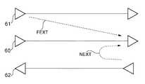
ところで、SNRを測定して各キャリアのパワー配分及びビット配分を求める場合には、漏話雑音を考慮する必要がある。一般に、漏話には遠端漏話と近端漏話とがある。これらについて、図6を参照して説明する。同図において、測定対象として着目している信号線路60と同一方向に信号が流れる信号線路61を漏話源とするものが遠端漏話FEXTである。本来伝送すべき信号も伝送距離と共に減衰するので、伝送距離に応じてこの遠端漏話FEXTの量も相対的に減衰する。したがって、この遠端漏話FEXTが発生している時には伝送距離に関わらずSNRは高い値を示すことになる。 By the way, when measuring the SNR and determining the power distribution and bit distribution of each carrier, it is necessary to consider crosstalk noise. In general, crosstalk includes far-end crosstalk and near-end crosstalk. These will be described with reference to FIG. In the figure, the far-end crosstalk FEXT is a signal having a signal line 61 in which a signal flows in the same direction as the
一方、測定対象として着目している信号線路60と逆方向に信号が流れる信号線路62を漏話源とするものが近端漏話NEXTである。本来伝送すべき信号が伝送距離と共に減衰するのに対して、近端漏話NEXTは本来伝送すべき信号の伝送先において漏話量が多いのでSNRは低い値を示すことになる。 On the other hand, near-end crosstalk NEXT is a signal having a
したがって、SNRの高い遠端漏話が生じている時には各キャリアのパワー配分及びビット配分を多くし、SNRの低い近端漏話が生じている時には各キャリアのパワー配分及びビット配分を少なくするのが適切である。 Therefore, it is appropriate to increase the power allocation and bit allocation of each carrier when a far-end crosstalk with a high SNR occurs, and reduce the power allocation and bit allocation of each carrier when a near-end crosstalk with a low SNR occurs. It is.
以上述べたように、本発明によれば、ビット配分及びパワー配分を雑音周期に応じて変化制御せしめることにより、雑音が比較的少ない場合において伝送量の増大を図ることができ、よって伝送効率の向上が可能となるという効果がある。 As described above, according to the present invention, the amount of transmission can be increased when the noise is relatively low by controlling the bit distribution and the power distribution in accordance with the noise period. There is an effect that improvement is possible.
以下に本発明の実施の形態につき図面を参照して説明する。
図1は本発明の概略システム構成を示す図であり、中央局としてXTU−C1、端末としてXTU−R2が、夫々設けられており、これ等両者間の伝送はディジタル加入者線により行われる。尚、XTU−CはXDSL Termination Unit-Center side であり、XTU−RはXDSL Termination Unit-Remote side である。ここに、XDSLはX Digital Subscriber Line を意味し、XはA,V,H等の総称である。Embodiments of the present invention will be described below with reference to the drawings.
FIG. 1 is a diagram showing a schematic system configuration of the present invention. An XTU-C1 is provided as a central office and an XTU-R2 is provided as a terminal, and transmission between the two is performed by a digital subscriber line. XTU-C is an XDSL Termination Unit-Center side, and XTU-R is an XDSL Termination Unit-Remote side. Here, XDSL means X Digital Subscriber Line, and X is a generic term for A, V, H, and the like.
XTU−C1及びXTU−R2共に、図示する様に、送信部3,6と受信部5,4とを夫々大きな機能として有している。これ等送受信機能の詳細が図2のブロック図に示されている。 As shown in the figure, both XTU-C1 and XTU-R2 have
図2を参照すると、XTU−C1の下り方向の機能(送信部3)は、入力データを一時蓄積するバッファ11と、雑音の周期に応じた各キャリアのパワー配分及びビット配分を行う(詳細は後述)マッピング部12と、このマッピング出力である多値QAM(Quadrature Amplitude Modulation)信号を各キャリアで変調多重化するIFFT(Inverse First Fourier Transform)部13と、この多重化出力をアナログ化して下り信号として送出するDAC(Digital to Analog Converter)部14とを有する。 Referring to FIG. 2, the downstream function of XTU-C1 (transmitting unit 3) performs buffer 11 for temporarily storing input data and power distribution and bit distribution for each carrier according to the period of noise (for details, see FIG. 2). A
また、XTU−C1の上り方向の機能(受信部5)は、伝送されてきた信号をディジタル信号に変換するADC(Analog to Digital Converter)部15と、このディジタル信号を復調するFFT(Fast Fourier Transform)部16と,音の周期に応じて伝送されてきた信号のビット配分を切換えて受信するデマッピング部17と、ビット配分によるデータ伝送量の変化を調整するためのバッファ18とを有している。尚、EC部19はエコーキャンセラ機能を有するブロックである。 The upstream function (reception unit 5) of the XTU-C1 includes an ADC (Analog to Digital Converter)
更に、本発明を実現すべく、XTU−C1は疑似ランダム信号発生部20と、トーン発生部21と、SNR測定部22と、パワー/ビット配分計算部23とを有している。疑似ランダム信号発生部20は全てのキャリアを含む疑似ランダム信号を生成してIFFT部13へ出力し、トーン発生部21はトーンを生成してIFFT部13へ出力する。SNR測定部22はXTU−R2より送信された疑似ランダム信号のSNRを雑音周期毎に算出する機能を有しており、パワー/ビット配分計算部23はこの測定されたSNRに従って雑音周期毎に各キャリアのパワー配分及びビット配分を算出し、IFFT部13及びデマッピング部17へ出力する。 Further, in order to realize the present invention, the XTU-C1 includes a pseudo random
また、XTU−R2の下り方向の機能(受信部4)は、伝送されてきた信号をディジタル信号に変換するADC部24と、このディジタル信号を復調するFFT部25と、雑音の周期に応じて伝送されてきた信号のビット配分を切換えて受信するデマッピング部26と、ビット配分によるデータ伝送量の変化を調整するためのバッファ27とを有している。 The XTU-R2 downstream function (reception unit 4) includes an ADC unit 24 that converts a transmitted signal into a digital signal, an
XTU−R2の上り方向の機能(送信部6)は、入力データを一時蓄積するバッファ28と、雑音の周期に応じた各キャリアのパワー配分及びビット配分を行う(詳細は後述)マッピング部29と、このマッピング出力である多値QAM信号を各キャリアで変調多重化するIFFT部30と、この多重化出力をアナログ化して上り信号として送出するDAC部31とを有する。 The XTU-R2 upstream function (transmission unit 6) includes a
更に、本発明を実現すべく、XTU−R2は疑似ランダム信号発生部36と、SNR測定部34と、パワー/ビット配分計算部35とを有している。疑似ランダム信号発生部36は全てのキャリアを含む疑似ランダム信号を生成してFFT部30へ出力し、SNR測定部34はXTU−C1より送信された疑似ランダム信号のSNRを雑音周期毎に算出する機能を有しており、パワー/ビット配分計算部35はこの測定されたSNRに従って雑音周期毎に各キャリアのパワー配分及びビット配分を算出し、IFFT部30及びデマッピング部26へ出力する。 Furthermore, in order to realize the present invention, the XTU-R2 includes a pseudo random signal generation unit 36, an
尚、XTU−C1側のクロックは、雑音周期に同期したクロックであり、この場合、当該雑音周期は既知であるものとする。例えば、雑音がTCM(Time Compression Multiplexing )方式のISDNからの漏話の場合には、図3に示す様に、近端漏話と遠端漏話とが800Hz毎に発生するために、各キャリアのSNRも800Hz毎に変化することになる。そのために、XTU−C1の送信部3では、800Hzのクロックを受けて、XTU−R2の受信部4へ当該クロックを送出することが必要になる。 The clock on the XTU-C1 side is a clock synchronized with the noise period, and in this case, the noise period is known. For example, in the case where the noise is crosstalk from a TCM (Time Compression Multiplexing) ISDN, as shown in FIG. 3, near-end crosstalk and far-end crosstalk occur every 800 Hz. It will change every 800 Hz. Therefore, it is necessary for the
すなわち、当該受信部4でその周期毎に各キャリアの受信SNRを計算することが必要であり、よって、その周期を知る手段として、XTU−C1の送信部において、トーン発生部21からのトーンを当該クロックに同期してレベルを制御せしめてXTU−R2へ送出している。このクロック周期すなわち雑音周期がクロック検出部33で検出可能となっており、この検出周期がマッピング部29及びデマッピング部26へ出力されている。 That is, it is necessary for the receiving
そして、XTU−R2の送信部にもトーン発生部37が設けられており、このトーン発生部37からのトーンを当該クロックに同期してレベルを制御せしめてXTU−C1へ送出する。XTU−C1にもクロック検出部38が設けられており、クロック周期が検出可能になっている。 A
なお、これらのクロックは、装置外部から入力しても良いし、クロックに同期したものを装置内部で生成しても良い。送信を開始するためのトリガとなる指令は中央局自身で生成しても良いし、他の装置である端局で生成しても良い。 Note that these clocks may be input from the outside of the apparatus, or those synchronized with the clock may be generated inside the apparatus. A command serving as a trigger for starting transmission may be generated by the central station itself or may be generated by a terminal station which is another device.
ところで、図1の構成においては、専用のトーン発生部21,37がXTU−C1,XTU−R2に設けられている。この専用のトーン発生部を設けずに、代わりにISDNにおいて用いられている周知のパイロットトーンを用いることもできる。こうすることにより、専用のトーン発生部を設ける必要がなくなり、ハードウェア量を低減できる。 Incidentally, in the configuration of FIG. 1,
図4は本発明の実施例の動作を示すフローチャートである。同図において、上から下に向う矢印は同一装置内における動作の流れを示し、左又は右方向の矢印は装置間の通信の流れを示す。 FIG. 4 is a flowchart showing the operation of the embodiment of the present invention. In the figure, arrows from the top to the bottom indicate the flow of operations within the same device, and the left or right arrows indicate the flow of communication between the devices.
同図を参照すると、図1におけるXTU−R2の受信部4において変化する雑音の周期(図3参照)を検知するために、XTU−C1の送信部3では、周期的に変化する雑音と同期したクロックに応じて(同期して)トーン発生部21からのトーンのレベルを変化させて送信する(ステップA1)。XTU−R2の受信部4においては、クロック検出部33にてこのトーンのレベル変化により雑音の周期を検出する(ステップB1)。 Referring to the figure, in order to detect the period of noise changing in the receiving
下り方向のDMT各キャリアのパワー配分とビット配分とを求めるために、XTU−C1の送信部3における疑似ランダム信号発生部20からの疑似ランダム信号を送出する(ステップA2)。この疑似ランダム信号はDMT全キャリアの成分を有するものとし、ANSI(American National Standards Institute )標準では256キャリアである。 In order to obtain the power distribution and bit distribution of each DMT carrier in the downlink direction, a pseudo random signal is transmitted from the pseudo random
この疑似ランダム信号はXTU−R2の受信部4で受信され、ステップB1にて検出されている周期毎に、SNR測定部34でSNRが測定される(ステップB2)。この測定SNRより各キャリアのビット数と送信パワーとが、パワー/ビット数配分計算部35にて算出され、その算出情報はデマッピング部26に記憶されると共に、IFFT部30を介してXTU−C1へ送信される(ステップB3)。XTU−C1では、この送信されてきたビット配分及び送信パワー配分とを、下りキャリア用情報としてマッピング部12にて記憶しておく(ステップA3)。 This pseudo-random signal is received by the receiving
以上は下りキャリア用ビット配分及び送信パワー配分を算出するための処理フローであるが、次に上りキャリア用配分及び送信パワー配分を算出するための処理につき説明する。XTU−R2の送信部6における疑似ランダム信号発生部36からの疑似ランダム信号(ANSI標準では、32キャリア)を、XTU−C1へ送信する(ステップB4)。XTU−C1の受信部5では、SNR測定部22にて送信されてきた疑似ランダム信号より、雑音に同期したクロックの周期毎にSNRを測定する(ステップA4)。 The above is the processing flow for calculating the downlink carrier bit distribution and the transmission power distribution. Next, the processing for calculating the uplink carrier distribution and the transmission power distribution will be described. The pseudo random signal (32 carriers in the ANSI standard) from the pseudo random signal generator 36 in the transmitter 6 of XTU-R2 is transmitted to XTU-C1 (step B4). The receiving
この測定されたSNRにより、各キャリアのビット数と送信パワーとが、パワー/ビット数配分計算部23て算出され、その情報はデマッピング部17に記憶されると共に、IFFT部13を介してXTU−R2へ送信される(ステップA5)。XTU−R2では、この送信されてきたビット配分及び送信パワー配分とを、上りキャリア用情報としてマッピング部29にて記憶しておく(ステップB5)。 Based on the measured SNR, the number of bits and the transmission power of each carrier are calculated by the power / bit number
通信開始と同時に、下り方向の伝送では、XTU−C1の送信部3では、マッピング部12において、変化する雑音の周期毎に記憶してある2種類(図3の例においては)のビット配分及び送信パワー配分を切換えてデータ送信を行う(ステップA6)。そして、XTU−R2の受信部4では、送信されてきたDMTデータをデマッピング部26にて記憶してあるビット数を基に抽出する。尚、ビット配分が周期的に変化するので、伝送量も変化することになり、バッファ27にてこれを調節している。 Simultaneously with the start of communication, in downlink transmission, in the
また、上り方向の伝送では、XTU−R2の送信部6では、マッピング部29において、変化する雑音の周期に応じて記憶してある2種類(図3の例では)のビット配分及び送信パワー配分を切換えてデータ送信を行う(ステップB6)。そして、XTU−C1の受信部5では、送信されてきたDMTデータをデマッピング部17に記憶されているビット数を基に抽出する。バッファ18により、ビット配分が周期的に変化することによる伝送量の調節を図っている。 Further, in uplink transmission, the XTU-R2 transmitting unit 6 stores two types of bit distribution and transmission power distribution stored in the
次に、図5を参照しつつ図4のステップA5,B3における各キャリアの送信パワー及びビット数の計算方法について、その一例を簡単に説明する。各キャリアiの送信電力をE(i)として正規化したSNR(i)を求める(ステップS1)。そして、SNR(i)/Γ(i)を算出する(ステップS2)。ここで、Γ(i)は「SNRgap 」と呼ばれるもので、以下の様になる。 Next, an example of the calculation method of the transmission power and the number of bits of each carrier in steps A5 and B3 in FIG. 4 will be briefly described with reference to FIG. Normalized SNR (i) is obtained with the transmission power of each carrier i as E (i) (step S1). Then, SNR (i) / Γ (i) is calculated (step S2). Here, Γ (i) is called “SNRgap” and is as follows.
Γ(i)=[Q-1(Pe /ne )]2 +γmargin−γeff −4.77(dB)
ここで、γmarginは装置のパフォーマンスマージン、γeff は誤り訂正における符号化利得である。Γ (i) = [Q−1 (Pe / ne)] 2 + γmargin−γeff−4.77 (dB)
Here, γmargin is a performance margin of the apparatus, and γeff is a coding gain in error correction.
次に、SNR(i)/Γ(i)の値を降順にソートする(ステップS3)。ここで、オリジナルのキャリア番号(i)とソートされたキャリア番号(i)との対応を記録しておく。そして、k=1,bmax =0,{b∧j}=0とする(ステップS4)。ここで、kはカウント値、{b∧j}は各キャリア毎のビット数、bmax は伝送量の合計値を示す。 Next, the values of SNR (i) / Γ (i) are sorted in descending order (step S3). Here, the correspondence between the original carrier number (i) and the sorted carrier number (i) is recorded. Then, k = 1, bmax = 0, and {b∧j} = 0 are set (step S4). Here, k is a count value, {b∧j} is the number of bits for each carrier, and bmax is a total transmission amount.
そして、btarget(k)を、
btarget(k)=Σbj
なる式にて算出する(ステップS5)。ここに、Σはj=1〜kの総和を示す。ここで、btarget(k)はk個のキャリアを使用した場合の伝送量の合計値であり、bj は、
round[log 2 {1+(EtargetSNR(j)/k)/Γ(i)}]
または、floor[log 2 {1+(Emax SNR(j))/Γ(i)}]
の値のうち小なる値を取る。尚、roundは四捨五入を示し、floorは切捨てを示す。And btarget (k) is
btarget (k) = Σbj
(Step S5). Here, Σ indicates the total sum of j = 1 to k. Here, btarget (k) is a total value of transmission amount when k carriers are used, and bj is
round [log 2 {1+ (EtargetSNR (j) / k) / Γ (i)}]
Or floor [log 2 {1+ (Emax SNR (j)) / Γ (i)}]
Takes the smaller value of. Note that round indicates rounding and floor indicates truncation.
もし、btarget(k)>bmax の場合、bmax =btarget(k)とする(ステップS6,S7)。そして、このときの各キャリアのビット配分bj をb∧j として記憶しておく。kがNに等しくなければ、k=k+1とおき(ステップS9)、ステップS5へ戻る。k=Nならば(ステップS8)、ステップS10へ進む。このときのbmax が最大伝送量となり、B∧jがそのときの各キャリアのビット配分となる。b∧jを並べ直したb∧iより、各キャリアの送信パワーE∧iを求める(ステップS10)。 If btarget (k)> bmax, bmax = btarget (k) is set (steps S6 and S7). The bit distribution bj of each carrier at this time is stored as b∧j. If k is not equal to N, k = k + 1 is set (step S9), and the process returns to step S5. If k = N (step S8), the process proceeds to step S10. At this time, bmax is the maximum transmission amount, and B∧j is the bit distribution of each carrier at that time. The transmission power E∧i of each carrier is obtained from b∧i obtained by rearranging b∧j (step S10).
そして、トータル電力Etotal として、
Etotal =ΣE∧i
を算出する(ステップS11)。尚、この場合のΣはi=0〜N−1の総和を示す。そして最終的なEi を、
EtargetE∧i/Etotal 又はEmax,i
のうち小なる値として求める(ステップS12)。ここでは、Etargetはトータル電力の最大値で予め与えられる。Emax は各キャリア毎の許容限界値である。And as total power Etotal,
Etotal = ΣE∧i
Is calculated (step S11). In this case, Σ represents the sum of i = 0 to N-1. And the final Ei
EtargetE∧i / Etotal or Emax, i
It calculates | requires as a small value among these (step S12). Here, Etarget is given in advance as the maximum value of the total power. Emax is an allowable limit value for each carrier.
上記実施例では、図3に示す様に雑音の周期が200Hzであり、雑音が2種の場合としているが、これは単に一例を示すものであり、3種以上の雑音や、またその周期も種々の値を取り得るものであるが、これ等は既知であるものとする。また、図5に示した計算方法の詳細については、上記USP5,479,447号公報に開示されているが、この方法に限定されるものでもない。 In the above embodiment, as shown in FIG. 3, the period of noise is 200 Hz, and there are two types of noise. However, this is merely an example, and three or more types of noise and their periods are also included. Although various values can be taken, these are assumed to be known. The details of the calculation method shown in FIG. 5 are disclosed in the above-mentioned USP 5,479,447, but are not limited to this method.
1 XTU−C
2 XTU−R
3,6 送信部
4,5 受信部
11,18,28,27 バッファ
12,29 マッピング部
13,30 IFFT部
14,31 DAC部
15,24 ADC部
16,25 FFT部
17,26 デマッピング部
19 EC部
20,36 疑似ランダム信号発生部
21 トーン発生部
22,34 SNR測定部
23,35 パワー/ビット計算部
1 XTU-C
2 XTU-R
3, 6
Claims (6)
Translated fromJapanese前記第2の装置を伝送路に接続して立上げる初期動作時において、前記第1の装置が、前記雑音の周期に同期するクロックを前記第2の装置とは異なる外部から受信することを特徴とするマルチキャリア伝送システム。At least one of bit distribution and transmission power distribution of each carrier of the multicarrier is calculated according to a periodically changing noise period, and data transmission is performed between the first and second devices based on the calculated distribution. A multi-carrier transmission system,
In the initial operation of startingup the second device connected to a transmission line, the first device receives a clock synchronized with the period of the noise from an external device different from that of the second device. Multi-carrier transmission system.
前記第2の装置を伝送路に接続して立上げる初期動作時において、前記第1の装置が、前記雑音の周期に同期するクロックを前記第2の装置とは異なる外部から受信し、前記クロックの周期に同期して状態が変化するトーンを前記第2の装置に送信することを特徴とするマルチキャリア伝送システム。At least one of bit distribution and transmission power distribution of each carrier of the multicarrier is calculated according to a periodically changing noise period, and data transmission is performed between the first and second devices based on the calculated distribution. A multi-carrier transmission system,
In the initial operation when the second device is connected to the transmission line and started up, the first device receives a clock synchronized with the period of the noise from an external device different from the second device, and the clock A multi-carrier transmission system, wherein a tone whose state is changed in synchronization with a period of the transmission is transmitted to the second device.
前記第2の装置を伝送路に接続して立上げる初期動作時において、前記第1の装置が前記雑音の周期に同期するクロックを前記第2の装置とは異なる外部から受信することを特徴とするマルチキャリア伝送方法。Calculate at least one of bit distribution and transmission power distribution of each carrier of the multicarrier according to the period of periodically changing noise, and perform data transmission between the first and second devices based on the calculated distribution A multi-carrier transmission method,
The first device receives a clock synchronized with the period of the noise from an external device different from that of the second deviceduring an initial operation in which the second device is connected to a transmission line and started up. Multi-carrier transmission method.
前記第2の装置を伝送路に接続して立上げる初期動作時において、前記第1の装置が前記雑音の周期に同期するクロックを前記第2の装置とは異なる外部から受信し、前記クロックの周期に同期して状態が変化するトーンを前記第2の装置に送信することを特徴とするマルチキャリア伝送方法。At least one of bit distribution and transmission power distribution of each carrier of the multicarrier is calculated according to a periodically changing noise period, and data transmission is performed between the first and second devices based on the calculated distribution. A multi-carrier transmission method,
In the initial operation of startingup the second device connected to the transmission line, the first device receives a clock synchronized with the period of the noise from an external device different from the second device, and A multi-carrier transmission method, wherein a tone whose state changes in synchronization with a period is transmitted to the second device.
6. The multicarrier transmission method according to claim5 , wherein the state is level.
Priority Applications (1)
| Application Number | Priority Date | Filing Date | Title |
|---|---|---|---|
| JP2004323134AJP4020118B2 (en) | 1998-02-27 | 2004-11-08 | Multi-carrier transmission system and transmission method |
Applications Claiming Priority (2)
| Application Number | Priority Date | Filing Date | Title |
|---|---|---|---|
| JP4653498 | 1998-02-27 | ||
| JP2004323134AJP4020118B2 (en) | 1998-02-27 | 2004-11-08 | Multi-carrier transmission system and transmission method |
Related Parent Applications (1)
| Application Number | Title | Priority Date | Filing Date |
|---|---|---|---|
| JP2002202944ADivisionJP3664154B2 (en) | 1998-02-27 | 2002-07-11 | Multi-carrier transmission system, transmission apparatus, and transmission method |
Related Child Applications (1)
| Application Number | Title | Priority Date | Filing Date |
|---|---|---|---|
| JP2007010493ADivisionJP4367489B2 (en) | 1998-02-27 | 2007-01-19 | Multi-carrier transmission system, transmission apparatus and transmission method |
Publications (2)
| Publication Number | Publication Date |
|---|---|
| JP2005102278A JP2005102278A (en) | 2005-04-14 |
| JP4020118B2true JP4020118B2 (en) | 2007-12-12 |
Family
ID=34466463
Family Applications (1)
| Application Number | Title | Priority Date | Filing Date |
|---|---|---|---|
| JP2004323134AExpired - Fee RelatedJP4020118B2 (en) | 1998-02-27 | 2004-11-08 | Multi-carrier transmission system and transmission method |
Country Status (1)
| Country | Link |
|---|---|
| JP (1) | JP4020118B2 (en) |
- 2004
- 2004-11-08JPJP2004323134Apatent/JP4020118B2/ennot_activeExpired - Fee Related
Also Published As
| Publication number | Publication date |
|---|---|
| JP2005102278A (en) | 2005-04-14 |
Similar Documents
| Publication | Publication Date | Title |
|---|---|---|
| US10148591B2 (en) | Method and multi-carrier transceiver with stored application profiles for supporting multiple applications | |
| EP1245093B1 (en) | Diagnostic methods and systems for multicarrier modems | |
| JP3152217B2 (en) | Wire transmission device and wire transmission method | |
| CA2643424C (en) | Multicarrier system with stored application profiles for supporting multiple applications | |
| EP3393076B1 (en) | Method and apparatus for differentiated communication channel robustness in a multi-tone transceiver | |
| EP2385634B1 (en) | System for emergency rate adjustment | |
| JPH11313043A (en) | Multicarrier transmission system, transmission equipment and transmission method | |
| US7688903B2 (en) | Multicarrier transmission apparatus and method | |
| JP4020118B2 (en) | Multi-carrier transmission system and transmission method | |
| JP4367489B2 (en) | Multi-carrier transmission system, transmission apparatus and transmission method | |
| JP3664154B2 (en) | Multi-carrier transmission system, transmission apparatus, and transmission method | |
| JP4488110B2 (en) | Multi-carrier transmission system, transmission apparatus and transmission method | |
| JP3082743B2 (en) | Multi-carrier transmission system and multi-carrier transmission method | |
| JP3348719B2 (en) | Multi-carrier transmission system, transmission device, and transmission method | |
| JP4032055B2 (en) | Communication method and communication system | |
| KR100926196B1 (en) | Multicarrier system with stored application profiles for supporting multiple applications | |
| US20150365131A1 (en) | Crosstalk Management For OFDM Communication Systems In Power Efficient Transmission Mode | |
| AU2017210489B2 (en) | Diagnostic methods and systems for multicarrier modems | |
| AU2014208320B2 (en) | Diagnostic methods and systems for multicarrier modems | |
| JP4821377B2 (en) | Multi-carrier transmission apparatus, multi-carrier transmission method and program |
Legal Events
| Date | Code | Title | Description |
|---|---|---|---|
| RD01 | Notification of change of attorney | Free format text:JAPANESE INTERMEDIATE CODE: A7421 Effective date:20050324 | |
| A131 | Notification of reasons for refusal | Free format text:JAPANESE INTERMEDIATE CODE: A131 Effective date:20061121 | |
| RD01 | Notification of change of attorney | Free format text:JAPANESE INTERMEDIATE CODE: A7421 Effective date:20070118 | |
| A521 | Written amendment | Free format text:JAPANESE INTERMEDIATE CODE: A523 Effective date:20070119 | |
| A02 | Decision of refusal | Free format text:JAPANESE INTERMEDIATE CODE: A02 Effective date:20070424 | |
| A521 | Written amendment | Free format text:JAPANESE INTERMEDIATE CODE: A523 Effective date:20070625 | |
| A911 | Transfer of reconsideration by examiner before appeal (zenchi) | Free format text:JAPANESE INTERMEDIATE CODE: A911 Effective date:20070808 | |
| TRDD | Decision of grant or rejection written | ||
| A01 | Written decision to grant a patent or to grant a registration (utility model) | Free format text:JAPANESE INTERMEDIATE CODE: A01 Effective date:20070904 | |
| A61 | First payment of annual fees (during grant procedure) | Free format text:JAPANESE INTERMEDIATE CODE: A61 Effective date:20070917 | |
| FPAY | Renewal fee payment (event date is renewal date of database) | Free format text:PAYMENT UNTIL: 20101005 Year of fee payment:3 | |
| R150 | Certificate of patent or registration of utility model | Free format text:JAPANESE INTERMEDIATE CODE: R150 | |
| FPAY | Renewal fee payment (event date is renewal date of database) | Free format text:PAYMENT UNTIL: 20111005 Year of fee payment:4 | |
| FPAY | Renewal fee payment (event date is renewal date of database) | Free format text:PAYMENT UNTIL: 20121005 Year of fee payment:5 | |
| FPAY | Renewal fee payment (event date is renewal date of database) | Free format text:PAYMENT UNTIL: 20131005 Year of fee payment:6 | |
| LAPS | Cancellation because of no payment of annual fees |