JP4018982B2 - Methods and instruments for interbody surgery techniques - Google Patents
Methods and instruments for interbody surgery techniquesDownload PDFInfo
- Publication number
- JP4018982B2 JP4018982B2JP2002537200AJP2002537200AJP4018982B2JP 4018982 B2JP4018982 B2JP 4018982B2JP 2002537200 AJP2002537200 AJP 2002537200AJP 2002537200 AJP2002537200 AJP 2002537200AJP 4018982 B2JP4018982 B2JP 4018982B2
- Authority
- JP
- Japan
- Prior art keywords
- body portion
- distractor
- extending
- flange
- main body
- Prior art date
- Legal status (The legal status is an assumption and is not a legal conclusion. Google has not performed a legal analysis and makes no representation as to the accuracy of the status listed.)
- Expired - Fee Related
Links
- 238000000034methodMethods0.000titleabstractdescription24
- 238000001356surgical procedureMethods0.000titleabstractdescription17
- 239000000523sampleSubstances0.000claimsdescription3
- 230000007423decreaseEffects0.000claims3
- 230000008878couplingEffects0.000claims1
- 238000010168coupling processMethods0.000claims1
- 238000005859coupling reactionMethods0.000claims1
- 239000007943implantSubstances0.000description26
- 239000000463materialSubstances0.000description16
- 238000013459approachMethods0.000description10
- 210000001519tissueAnatomy0.000description10
- 210000000988bone and boneAnatomy0.000description9
- 238000003780insertionMethods0.000description9
- 230000037431insertionEffects0.000description9
- 230000004927fusionEffects0.000description8
- 210000005036nerveAnatomy0.000description8
- 125000006850spacer groupChemical group0.000description6
- 210000005166vasculatureAnatomy0.000description6
- 208000014674injuryDiseases0.000description5
- 230000008733traumaEffects0.000description5
- 208000002193PainDiseases0.000description2
- 230000032683agingEffects0.000description2
- 230000008901benefitEffects0.000description2
- 230000008468bone growthEffects0.000description2
- 230000006872improvementEffects0.000description2
- 230000013011matingEffects0.000description2
- 238000012986modificationMethods0.000description2
- 230000004048modificationEffects0.000description2
- 238000012545processingMethods0.000description2
- 230000002792vascularEffects0.000description2
- 239000011800void materialSubstances0.000description2
- 208000004044HypesthesiaDiseases0.000description1
- 208000010428Muscle WeaknessDiseases0.000description1
- 206010028372Muscular weaknessDiseases0.000description1
- 208000028389Nerve injuryDiseases0.000description1
- 206010033799ParalysisDiseases0.000description1
- 230000002159abnormal effectEffects0.000description1
- 230000003466anti-cipated effectEffects0.000description1
- 206010003246arthritisDiseases0.000description1
- 238000004140cleaningMethods0.000description1
- 238000012790confirmationMethods0.000description1
- 230000007547defectEffects0.000description1
- 230000002638denervationEffects0.000description1
- 201000010099diseaseDiseases0.000description1
- 208000037265diseases, disorders, signs and symptomsDiseases0.000description1
- 210000001951dura materAnatomy0.000description1
- 238000000605extractionMethods0.000description1
- 208000034783hypoesthesiaDiseases0.000description1
- 238000003384imaging methodMethods0.000description1
- 238000012978minimally invasive surgical procedureMethods0.000description1
- 230000004899motilityEffects0.000description1
- 230000008764nerve damageEffects0.000description1
- 231100000862numbnessToxicity0.000description1
- 238000002355open surgical procedureMethods0.000description1
- 230000000399orthopedic effectEffects0.000description1
- 230000000149penetrating effectEffects0.000description1
- 230000035515penetrationEffects0.000description1
- 230000008569processEffects0.000description1
- 230000001737promoting effectEffects0.000description1
- 230000000717retained effectEffects0.000description1
- 230000000007visual effectEffects0.000description1
Images


Classifications
- A—HUMAN NECESSITIES
- A61—MEDICAL OR VETERINARY SCIENCE; HYGIENE
- A61B—DIAGNOSIS; SURGERY; IDENTIFICATION
- A61B17/00—Surgical instruments, devices or methods
- A61B17/16—Instruments for performing osteoclasis; Drills or chisels for bones; Trepans
- A61B17/17—Guides or aligning means for drills, mills, pins or wires
- A61B17/1739—Guides or aligning means for drills, mills, pins or wires specially adapted for particular parts of the body
- A61B17/1757—Guides or aligning means for drills, mills, pins or wires specially adapted for particular parts of the body for the spine
- A—HUMAN NECESSITIES
- A61—MEDICAL OR VETERINARY SCIENCE; HYGIENE
- A61B—DIAGNOSIS; SURGERY; IDENTIFICATION
- A61B17/00—Surgical instruments, devices or methods
- A61B17/16—Instruments for performing osteoclasis; Drills or chisels for bones; Trepans
- A61B17/1662—Instruments for performing osteoclasis; Drills or chisels for bones; Trepans for particular parts of the body
- A61B17/1671—Instruments for performing osteoclasis; Drills or chisels for bones; Trepans for particular parts of the body for the spine
- A—HUMAN NECESSITIES
- A61—MEDICAL OR VETERINARY SCIENCE; HYGIENE
- A61B—DIAGNOSIS; SURGERY; IDENTIFICATION
- A61B17/00—Surgical instruments, devices or methods
- A61B17/32—Surgical cutting instruments
- A61B17/320016—Endoscopic cutting instruments, e.g. arthroscopes, resectoscopes
- A—HUMAN NECESSITIES
- A61—MEDICAL OR VETERINARY SCIENCE; HYGIENE
- A61B—DIAGNOSIS; SURGERY; IDENTIFICATION
- A61B17/00—Surgical instruments, devices or methods
- A61B17/16—Instruments for performing osteoclasis; Drills or chisels for bones; Trepans
- A61B17/1604—Chisels; Rongeurs; Punches; Stamps
- A—HUMAN NECESSITIES
- A61—MEDICAL OR VETERINARY SCIENCE; HYGIENE
- A61B—DIAGNOSIS; SURGERY; IDENTIFICATION
- A61B17/00—Surgical instruments, devices or methods
- A61B17/00234—Surgical instruments, devices or methods for minimally invasive surgery
- A61B2017/00238—Type of minimally invasive operation
- A61B2017/00261—Discectomy
- A—HUMAN NECESSITIES
- A61—MEDICAL OR VETERINARY SCIENCE; HYGIENE
- A61B—DIAGNOSIS; SURGERY; IDENTIFICATION
- A61B17/00—Surgical instruments, devices or methods
- A61B17/02—Surgical instruments, devices or methods for holding wounds open, e.g. retractors; Tractors
- A61B17/025—Joint distractors
- A61B2017/0256—Joint distractors for the spine
Landscapes
- Health & Medical Sciences (AREA)
- Surgery (AREA)
- Life Sciences & Earth Sciences (AREA)
- Orthopedic Medicine & Surgery (AREA)
- Biomedical Technology (AREA)
- Public Health (AREA)
- Veterinary Medicine (AREA)
- Engineering & Computer Science (AREA)
- Nuclear Medicine, Radiotherapy & Molecular Imaging (AREA)
- Heart & Thoracic Surgery (AREA)
- Medical Informatics (AREA)
- Molecular Biology (AREA)
- Animal Behavior & Ethology (AREA)
- General Health & Medical Sciences (AREA)
- Dentistry (AREA)
- Oral & Maxillofacial Surgery (AREA)
- Prostheses (AREA)
- Surgical Instruments (AREA)
- Materials For Medical Uses (AREA)
Abstract
Description
Translated fromJapanese【0001】
(発明の分野)
本発明は、脊椎手術技法および器具に関するものである。より詳細には、本発明の態様には他の応用例もあり得るが、本発明は、椎体間脊椎手術に適切な器具および技法を提供する。
【0002】
(発明の背景)
通常は、隣接する椎骨終板の間に位置する椎間円板は、脊椎を安定させ、椎骨とクッション椎体の間で力を分散させる。これらの椎間円板は、外傷、疾患または加齢により変位しあるいは損傷を受ける場合がある。脱漏または断裂した線維輪によって、神経損傷、疼痛、痺れ、筋衰弱、および麻痺さえも生じる恐れがある。さらには、通常の老化過程の結果として、円板が脱水および硬化し、それによって円板空隙の高さが減少し、かつ脊椎が不安定になり、運動性が減退するようになる。円板空隙の最も典型的な矯正手術に椎間円板切断(手術による椎間円板の一部または全部の摘出)がある。この椎間円板切断には、融合装置などのインプラントを収容する椎骨終板の作成がしばしば伴う。隣接する椎骨の融合によって、異常な関節力学、関節炎の早期進行および脊椎組織への損傷に伴う疼痛を和らげる。
【0003】
脊椎の欠陥を矯正する従来型の外科的処置は、脊椎に隣接する神経および脈管構造にかなりの外傷を引き起こす恐れがある。円板および骨物質を除去して融合装置、脊椎間のスペーサ、または他のインプラントのための円板空隙を作成するために、外科的処置に円板空隙中で切断器具の使用を要するとき、組織外傷の可能性が特に問題となり得る。このような予想される外傷を最小限にするために、外科的処置に円板空隙と隣接する組織の除神経および脈管遮断を要する場合がある。他の処置でも円板空隙に確実にアクセスするためには、神経および脈管構造の処理が必要である。手術器具と接触する可能性は減少するが、神経および脈管構造の処理および摘出は依然として外傷を招きかつ外科的処置に要する時間と困難を増大する恐れがある。
【0004】
参照によりその全体を本明細書に組み込む、Wilhelmyに付与された米国特許第5,722,977号が、椎間陥凹を設けるために1対の椎骨組織の角塊を摘出するための方法および器具を開示する。この器具には、椎間ほぞ穴カッターおよびこのカッターを案内する役割を果たすスペーサを含む。この処置には最初に椎体間にスペーサを挿入する必要がある。カッターは、スペーサを収容する空洞を画定する切断ヘッドを有する。骨物質を摘出するために、切断ヘッドをスペーサの回りに押し込んで円板空隙中に挿入する。特許第5,722,977号に開示されている、この器具の1つの欠点は、スペーサと隣接する神経ならびに脈管構造の間に切断ヘッドを配置することにある。
【0005】
Michelsonに付与された米国特許第5,484,437号が、手術時に周囲の組織および神経構造を保護する、後方手術進入路から融合装置を挿入するための技法および関連器具を開示する。この特許第5,484,437号がさらに詳細に説明するように、この外科的処置は、必要な手術器具を導入し易くするために椎体を引き離す貫入部を有する伸延器(distractor)の使用を伴う。特許第5,484,437号はまた、この伸延器によって作成した円板空隙に隣接する椎骨中に食い込む、一端に歯を有する中空スリーブを開示する。これらの歯が椎骨に食い込んで、伸延器の取出し後に続く処置工程の間、円板空隙の高さを維持する。特許第5,484,437号の1つの態様によれば、この中空のスリーブを介してドリルを通し、融合装置を挿入するための穴を予め作成しておくために円板物質および椎骨の一部を除去する。この技法に関する1つの欠点は、このような処置がスリーブを介して行われ、したがって外科医の操作スペースおよび視野が制約を受けることである。他の欠点は、予め作成した円板空隙の高さが、伸延器の貫入部とスリーブ内径の間の間隔によって限定されることである。
【0006】
以前に比べて最近の技法および器具は、椎骨の間にインプラントを挿入するための円板空隙を作成する外科的処置に進歩が認められるが、依然として改善の必要性がある。本発明は、このような改善の必要性に関するものであり、安全かつ効果的な脊椎の外科的処置のための方法および器具を提供する。
【0007】
(発明の概要)
本発明は、切断器具から隣接する組織を保護する1対のフランジを有する、脊椎円板空隙伸延器に関する。本発明はまた、1つまたは複数のインプラントを中に挿入するための円板空隙を作成するために、円板空隙を伸延かつ切断する脊椎用器具組立体に関する。本発明はさらに、伸延器および脊椎器具組立体を使用する外科的方法および処置に関する。
【0008】
本発明の1つの態様によれば、伸延器が提供される。この伸延器は、前端と後端の間に延在する本体部を含む。本体部は、上面および対向する下面を有し、かつ対向する第1および第2側壁が、この上面と下面の間に延在する。第1フランジと第2フランジが、本体部の前端からその後端に向かって延在する。これらの第1および第2フランジは、第1および第2側壁の一方からそれぞれに一定の間隔をおいて離間する。
【0009】
本発明の他の態様によれば、前端と後端の間に延在する本体部を含む伸延器が提供される。この本体部は、上面および対向する下面を有し、かつ対向する第1および第2側壁が、この上面と下面の間に延在する。本体部は、その中に形成した、上面と下面の間に延在する空洞を含む。
【0010】
本発明の別の態様によれば、隣接する椎骨の間の円板空隙を伸延かつ切断するための脊椎用器具組立体が提供される。この組立体は、伸延器とカッターを含む。伸延器は、前端と後端の間に延在する本体部を含む。本体部は、隣接する椎体の間に延びる、対向する第1および第2側壁を含む。伸延器はまた、本体部の前端から本体部の後端に向かって延在する第1フランジと第2フランジとを含む。第1および第2フランジはそれぞれ、第1および第2側壁の一方と共に、それぞれに本体部に沿って溝穴を形成する。細長い柄が、本体部の後端から近位方向に延びる。カッターは、軸の遠位端に切断ヘッドを含む。上部材、下部材、およびそれらの間に延在する1対の側壁が、軸と切断ヘッドを構成する。溝が切断ヘッドと軸を貫通する。この溝は、伸延器の柄を収容し、さらにカッターの側壁の遠位端が溝穴中で位置決め可能でありかつ伸延器の本体部が溝中に収容されるように、伸延器の本体部を収容するようにサイズ決めされている。
【0011】
本発明の他の態様によれば、伸延器は、伸延器を収容するようにサイズ決めされた溝を有する相互嵌合カッターを備える。このカッターは、伸延器の幅よりも狭い幅を有する。
【0012】
本発明の別の態様によれば、隣接する椎骨の間に円板空隙を作成する方法が提供される。この方法が、患者の皮膚および組織に貫入して円板空隙にアクセスするステップと、この円板空隙中に伸延器を挿入するステップであって、伸延器が前端と後端の間に延在する本体部を有し、さらに伸延器は、本体部の前端から本体部の後端に向かって延在する第1フランジと第2フランジを含み、この第1および第2フランジが本体部に沿ってそれぞれに溝穴を形成する、挿入ステップと、切断ヘッドを本体部上にかつ溝穴中で位置決めするステップとを含む。
【0013】
本発明の他の実施形態、形態、態様、目的、特徴、便益、および利点は、ここに供する詳細な図面および説明から明らかになろう。
(好ましい実施形態の詳細な説明)
本発明の原理の理解を助長する目的のために、図面に例示する実施形態を参照し、特定の用語を使用して本発明を説明する。しかしながら、それによって本発明の範囲を限定するものではないことが理解されよう。本発明が関連する技術分野の当業者なら考え付くような、説明されている過程、システムまたは装置における変更および他の変形、ならびに本発明の原理の他の応用例はいずれも企図されているものである。
【0014】
本発明の器具および方法は、広範な外科的処置に対して応用例を有し、特に円板空隙中にインプラントを挿入するための円板空隙を作成するための脊椎処置に応用例を有する。本発明の手術器具および方法は、切開外科的処置および最小限の侵襲性外科的処置に応用例を有することが企図されている。
【0015】
ここで図1を参照すると、隣接する上側と下側の椎骨間の円板空隙中に挿入可能な伸延器組立体10が提供されている。伸延器組立体10は、ハンドル継ぎ手14を介して柄16の近位端に連結するハンドル12を含む。伸延器18が、柄16の遠位端に固定されている。伸延器18を柄16に恒久的に付着するかまたはそれに着脱可能に取り付けできるように企図されている。
【0016】
ここで図2を参照すると、伸延器18は、前端22と後端24の間に延在する本体20を含む。伸延器18は前端22で本体部20に固定した第1フランジ26および第2フランジ28によって形成する1対の対向する最外部の側壁を有する。フランジ26、28は前端22から後端24に向かって延在する。フランジ26、28は、前端22で本体部20と一体形成されていることが好ましい。例示の実施形態では、第1端壁46が前端22と第1フランジ26の間に延在し、かつ第2端壁48が前端22と第2フランジ28の間に延在する。しかし、フランジ26、28を本体部20に着脱可能に取り付けることもできる。
【0017】
本体部20は、第1側壁30および対向する第2側壁32を有する。図3に示すように、側壁30、32はそれぞれ、本体部20の上面34および下面36の間で隣接する椎骨に向かって延在する。図2に戻ると、第1溝穴42が第1フランジ26と第1側壁30の間に形成されている。第2溝穴44は、第2フランジ28と第2側壁32の間に形成されている。溝穴42および44は、下で詳しく論じるように、切断器具52の遠位端を収容するようにサイズ決めされた幅「d」を有する。
【0018】
本体部20は、それを貫通して形成した、上面34と下面36の間に延在する空洞38をさらに含む。本体部20は、伸延させた円板空隙の所望の高さに対応する、上面34と下面36の間の高さH1を有する。例示の実施形態では、本体部20の前端部が、上面34と下面36の間の低減高さH2まで前端22で先細りになって、伸延器18を円板空隙中に挿入し易くしてある。フランジ26、28は本体部20の高さH1と等しいかまたはそれよりも低い高さを有し、かつ前端22に向かって先細りになっている本体部20に対応する先細部を有するのが好ましい。伸延器18を円板空隙中に挿入する深さは、円板空隙中に挿入した目視要素または伸延器18のX線または透視画像によって直視下で監視可能である。
【0019】
図2〜5を参照すると、本発明の別の態様にしたがって、脊椎用器具組立体50を形成するために、伸延器18と協働しかつそれと相互に嵌合可能な切断器具すなわちカッター52が提供されている。脊椎用器具組立体50は、インプラントの挿入箇所を形成するように、隣接する椎骨を伸延しかつ円板空隙および/または隣接する椎骨から物質を切断するために備わっている。カッター52は、軸64と、この軸64の遠位端に切断ヘッド53を有する。軸64には第1側壁58と対向する側壁60がある。側壁58および60は、上部材54と対向する下部材56によって連結されている。上部材54がその遠位端に上刃54aを含み、かつ下部材56がその遠位端に下刃56aを含む。例示の実施形態は、正方形の断面形状を備える軸64を有するが、例えば、円形または三角形の断面など他の形状も企図されている。
【0020】
軸64は、それを貫通して形成した、カッター52の遠位端で開く内溝62を含む。図4(a)に示すように、溝62は、柄16からハンドル12を取り去った伸延器組立体10の柄16と本体部20を収容するような寸法の第1遠位部62aを有する。第1遠位部62aは、本体部20よりも若干大きめの寸法を有しかつ本体部20の形状に近似する形状を有することが好ましい。これによって、円板空隙中および隣接する椎体の骨物質の中に切断ヘッド53を案内することになる、本体部20と切断ヘッド53の間に滑嵌めが備わる。溝62の残りの近位部分断面は任意の形状を有し得るが、溝62の全長にわたって第1部62aの形状に対応する形状を有することが好ましい。
【0021】
伸延器18の第1フランジ26と第2フランジ28の間における全幅W1は、カッター52の側壁58と60の間の幅W2よりも広い。したがって、伸延器18とカッター52を嵌め合わせるとき、伸延器18は、カッター52の刃ではなく、確実に伸延器18のフランジすなわち最外部の側壁が神経および脈管構造に隣接して位置するようになる。
【0022】
図4(b)に示す1つの代替形態では、溝62に、柄16よりも若干大きめの寸法と柄16の外面に近似する断面形状を有する第2近位部62bが備わっている。これによって、カッター52が柄16に沿って滑動して前進するとき、柄16とカッター52の間の相対的な動きが最小限になる。
【0023】
図6に示す1つの代替実施形態では、伸延器18’が、第1側壁30’、対向する第2側壁32’、上面34’および下面36’によって画定される円形断面を備える本体部20’を有する。第1フランジ26’および第2フランジ28’は、縦方向に配向したフランジも同様に設け得るが、本体部20’に平行な湾曲形状をそれぞれに有する。第1溝穴42’を第1フランジ26’と側壁30’の間に形成し、かつ第2溝穴44’を第2フランジ28’と側壁32’の間に形成する。この実施形態では、カッターには、その遠位端に円形開口と、手動または他の知られている動力手段で本体20’回りに回転して隣接する椎骨終板を切断可能にする断面形状とが備わる。フランジ26’および28’は、回転する切断ヘッドから隣接する組織を保護する。別法として、非回転式カッターを伸延器18’に使用することもできる。
【0024】
図7に示す別の実施形態では、伸延器18”が、上面34”と側壁30”の間に形成した第1上溝21”および上面34”と側壁32”の間に形成した第2上溝23”を有する。さらに伸延器18”は、下面36”と側壁30”の間に形成した第1下溝25”および下面36”と側壁32”の間に形成した第2下溝27”を有する。カッター52の溝はこれらの溝と相互に嵌合するように構成され、したがってこれらの溝によってカッターの刃を円板空隙中に案内することができる。第1溝穴42”を第1フランジ26”と側壁30”の間に形成し、かつ第2溝穴44”を第2フランジ28”と側壁32”の間に形成する。溝21”、23”、25”および27”が、伸延器18”に対して切断刃の上向きおよび下向きの動きに抵抗すると共に、フランジ26”および28”が切断刃から隣接組織を保護する。
【0025】
再び図2〜5を参照すると、上部材54は開口68を含み、かつ下部材56が開口68と同一の開口70(図4(a))を含む。これらの開口は、伸延器18の空洞38と実質的に位置合わせ可能であり、骨物質を切断後に器具組立体を円板空隙から引き出すとき、空洞38から切断物質を取り出し易くする。カッター側壁60がその中に形成した凹部72を含み、かつカッター側壁58が同じ形状の凹部(図示せず)を含む。これらの凹部によって、伸延器18の前端22を越えて、刃54aおよび56aを前方に送ることができる。端壁46、48が、切断ヘッド53が本体部20の前端22を越えて前方に行き過ぎるのを防止する。
【0026】
側壁60は、伸延器組立体10の柄16上の深さ目印を視認可能にすることによって、伸延器18に対する切断ヘッド53の位置をさらに目視および/または確認できる窓80を含む。軸64は、カッター52の画像による案内によって制御および監視できるように、その近位端に隣接して画像プローブ74をさらに含む。プローブ74に関するさらに詳細な説明が、Foley他に付与された米国特許第6,021,343号に記載されているが、その全体を参照により本明細書に組み込む。切断ヘッド53を円板空隙中に挿入するとき、それを視認するためのX線または透視画像技法を使用することも企図されている。
【0027】
軸64は、インプラントを挿入するために作成した円板空隙の所望高さに対応する高さH3をその遠位端に有する。上部材54と下部材56が椎骨終板に対して平行にカッター52を円板空隙中に挿入し、かつそのカッターを伸延器18の本体部20が案内するように企図されている。椎骨終板から骨組織を摘出するために、高さH3を増大させたいくつかのカッター52を備えて、伸延器18上に順次に挿入できることがさらに企図されている。例示のカッター52は平坦な刃54a、56aを有するが、刃には他の形状も企図する。例えば、丸い上刃および下刃を使用して椎骨終板の中にアーチ状の経路を切り取ることも可能である。カッター52の把持および制御を容易にするために、標準的な継ぎ手76をカッター52の近位端に設けてカッターハンドル78に取り付ける。刃54a、56aを骨物質の中に駆動するために、カッター52の近位端にスラップハンマなどの駆動具を連結または接触させることもできる。
【0028】
本発明の1つの態様による脊椎外科処置の工程を図8〜11に示す。図示の工程では、後方側Pと前方側Aを有する隣接椎体の間の円板空隙Dが例示してある。皮膚および組織を摘出し、かつ知られている任意の手術技法および器具を使用して円板空隙Dにアクセスする。一般的には、所望の進入箇所の円板環帯中に穴を作成し、かつ円板核の全部または一部をこの環帯を介して摘出することができる。図8に示すように、伸延器組立体10の伸延器18を円板空隙Dに挿入して、隣接する椎骨間に所望の高さまで円板空隙を伸延する。必要ならば、伸延器18を挿入する前に、知られている伸延器具によって円板空隙を順次伸延できるし、あるいは所望の円板空隙の高さを得るまで、高さH1を増大させたいくつかの伸延器18によって円板空隙を順次伸延することができる。
【0029】
所望の高さに達したら、ハンドル12を柄16の近位端から取り外し、かつ図9に示すように、カッター52を柄16の近位端上を滑動させて切断ヘッド53を円板空隙と伸延器18に隣接して配置する。図10および11に示すように、カッター52を伸延器18の本体部20上を前方に送り、椎骨終板の骨物質を刃54aおよび56aによって切断する。少なくとも切断物質の一部が伸延器18の空洞38内に保留される。カッター52がインプラントを挿入するための経路または通路を形成すると共に、伸延器18が円板空隙を伸延状態に維持する。フランジ26、28は、カッター52が本体部20上を前進しかつそれと相互に嵌合するとき、硬膜Sおよび神経根Nなどの隣接する脈管構造を保護する。
【0030】
インプラントの挿入経路を椎骨終板中に所望の深さまで切断すると、伸延器組立体10およびカッター52を円板空隙Dから取り出すことができる。空洞38中の物質をカッター52の開口68、70を介して除去して器具の分解を容易にする。必要ならば、1つまたは複数のインプラントを円板空隙に挿入する前に、円板空隙D中でさらに掃除および残片の摘出を済ませることができる。挿入インプラントは、円板空隙に挿入するのに適切な任意の装置でよい。1つの特定の形態では、円板高さの復元、部分間の位置決めおよび均衡の復元、および不安定で変質した椎間領域の固定のためにインプラントを円板空隙に挿入することを企図する。インプラント(または複数のインプラント)を知られている任意の器具または道具で適宜に移植可能であり、かつインプラントを円板空隙内に確実に保持および挿入するものなら任意の器具が企図されている。1つの特定の形態では、インプラントが、骨ドエル、圧入インプラント、ねじ込みインプラントなどの、本発明の器具によって作成した患者の円板空隙の部位中に送り込む融合装置である。この挿入インプラントは、隣接する椎骨の支持体となり、かつ融合を促進するために骨成長材料を充填することができる。インプラントを用いずにまたは挿入インプラントの回りに詰め物を用いず、移植材料を円板空隙中に作成した穴の中に直接配置することも可能である。
【0031】
円板空隙に至る単一横方向または大孔(transforaminal)進入路を介して、または円板空隙に至る前方または後方正中進入路を同時にとる複数進入路を介して、複数のインプラントを円板空隙中の2方向の箇所に挿入することも企図する。これらの挿入インプラントは、隣接する椎骨を2方向から支持し、かつ融合を助長する骨成長材料を充填することができる。
【0032】
脊椎に至る斜め後方進入路から円板空隙を作成しかつインプラントを挿入する特定の応用例を参照して、これらの器具および方法を開示してきた。しかし、単一後方進入路、横方向進入路、他の斜方進入路、および前方進入路を含めて、これらに限定しないが、多様な手術応用例および進入路に使用するために、これらの器具および方法を利用または改良可能であることが理解されよう。これらの器具はまた、1998年9月15日出願の米国特許出願第09/160,882号(その全体を参照により本明細書に組み込む)において説明されている作業溝用カニューレ/内視鏡を介するような、脊椎に対する腹腔鏡または内視鏡処置に関する応用例も有する。
【0033】
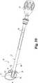
さらに図12および13をここで参照して、伸延器によって案内されるカッターを有する脊椎用器具組立体の別の実施形態を説明する。組立体150が、前端122と後端124の間に延在する本体部120を有する伸延器118を含む。本体120が後端124で柄116に取り付けてある。伸延器118は、本体部120によって形成した1対の対向する最外部の側壁126、128を有する。1つの形態では、溝穴142が、前端122に隣接する位置から本体部120と柄116まで近位方向に延在する。溝穴142は、実質的に伸延器118の長手中心軸に沿って延びるのが好ましい。端壁146が前端122と溝穴142の間に形成してある。
【0034】
本体部120は、それを貫通して形成した、本体部120の上面と下面の間に延在する空洞138をさらに含む。本体部は、伸延した円板空隙に見合う所望の高さに対応する高さを上面と下面の間に有する。伸延器18に関して上で説明したように、本体部120の前端部を先細りにすることができる。
【0035】
脊椎用器具組立体150を形成するために、伸延器118と協働しかつ相互に嵌合する切断器具すなわちカッター152が備わる。カッター152は、軸164の遠位端に軸164と切断ヘッド153を含む。軸164は、第1側壁158と対向する側壁160を含む。側壁158および160は、上部材154および対向する下部材156によって連結されている。上部材154はその遠位端に上刃154aを含み、かつ下部材156がその遠位端に下刃156aを含む。上部材154は開口168を含み、かつ下部材156が伸延器118の空洞138と実質的に位置合わせ可能な開口(図示せず)を含み、空洞138から切断した物質を取り出し易くする。カッターの側壁160は、その中に形成した凹部172を含み、カッターの側壁158は同じ形状の凹部(図示せず)を含む。
【0036】
軸164は、それを貫通して形成した、カッター152の遠位端で開く内部溝162を含む。溝162は、伸延器118の柄116と本体部120を収容するようにサイズ決めされている。これによって、切断ヘッド153を円板空隙および隣接する椎体の骨物質中に案内する、本体部120と切断ヘッド153の間の滑嵌めが備わる。側壁の凹部は、伸延器118の本体部120を収容するような寸法および形状になっており、刃154aおよび156aを伸延器118の前端122を越えて前方に送ることができる。端壁146は、切断ヘッド153が前端122を越えて前方に行き過ぎるのを防止する。
【0037】
溝穴142が伸延器118中に備わり、第1案内ピン171および第2案内ピン173が溝162中で位置決めされている。案内ピン171、173は、上部材154と下部材156の間に延在しかつそれらに固定してある。案内ピン171、173を案内溝穴142中に滑動可能に収容する。カッター152を本体部120上を前方に送ることが可能であり、この本体部120は溝162中に位置し、さらに側壁凹部172中に収容されかつその凹部から横方向に外側へ延在する。案内溝穴142中に位置する案内ピン171、173は、カッター152を伸延器118上を前方に送るとき、切断ヘッド153が本体部120に対して横方向にずれるのを防止する。ピン171、173はさらに、側壁の凹部領域で軸164を安定かつ強化する支柱としての役割も果たす。
【0038】
伸延器118は、第1側壁126と第2側壁128の間の全幅W1がカッター152の側壁158と160の間の幅W2よりも大きい。案内溝穴142および案内ピン171、173と、伸延器118とカッター152の間の相互に嵌合する配置とによって、カッター152の刃ではなく、伸延器118の側壁が、確実に神経および脈管構造に隣接して位置するようになる。
【0039】
本発明を図面および以上の記載において例示かつ詳細に説明してきたが、本発明は、特徴において例示的であり、したがって限定するものではないことが考慮されている。好ましい実施形態のみを示しかつ説明しており、したがって本発明の趣旨の範囲内に包摂されるすべての変形および変更の保護が望まれていることを理解されたい。
【図面の簡単な説明】
【図1】 本発明の1つの態様による伸延器組立体を示す上面図である。
【図2】 図1の伸延器組立体の遠位端部およびカッターの遠位端部を示す拡大上面図である。
【図3】 図2の伸延器およびカッターの遠位端部を示す側部立面図である。
【図4】 本発明の他の態様による伸延器/カッター組立体を示す図である。
図4(a)は、図4の線4(a)−4(a)を通って取った断面図である。
図4(b)は、図4の線4(b)−4(b)を通って取った断面図である。
【図5】 図4の伸延器/カッター組立体を示す斜視図であり、カッターの近位端にハンドルが取り付けてある。
【図6】 本発明による一代替実施形態の伸延器を示す断面図である。
【図7】 本発明による他の実施形態の伸延器を示す断面図である。
【図8】 図1の伸延器組立体を示す上面図であり、ほぼ後方進入路から円板空隙中に挿入されている。
【図9】 図5の伸延器/カッター組立体を示す上面図であり、伸延器が円板空隙中にありかつカッターが円板空隙に隣接している。
【図10】 図5の伸延器/カッター組立体を示す図であり、伸延器とカッターが円板空隙中にある。
【図11】 円板空隙中にある伸延器とカッターの遠位端部を示す拡大図である。
【図12】 本発明による別の実施形態の伸延器とカッターの遠位端部を示す拡大上面図である。
【図13】 図12のカッターの遠位端部を示す側部立面図である。[0001]
(Field of Invention)
The present invention relates to spinal surgery techniques and instruments. More particularly, the present invention provides instruments and techniques suitable for interbody spinal surgery, although there may be other applications for aspects of the present invention.
[0002]
(Background of the Invention)
Usually, an intervertebral disc located between adjacent vertebral endplates stabilizes the spine and distributes forces between the vertebrae and the cushion vertebral body. These intervertebral discs may be displaced or damaged by trauma, disease or aging. A missing or torn annulus can cause nerve damage, pain, numbness, muscle weakness, and even paralysis. Furthermore, as a result of the normal aging process, the disc dehydrates and hardens, thereby reducing the height of the disc void and making the spine unstable and reducing motility. The most typical orthopedic surgery for disc space is intervertebral disc cutting (extraction of part or all of an intervertebral disc by surgery). This discectomy is often accompanied by the creation of a vertebral endplate that houses an implant, such as a fusion device. The fusion of adjacent vertebrae relieves the pain associated with abnormal joint mechanics, early progression of arthritis, and damage to spinal tissue.
[0003]
Conventional surgical procedures that correct spinal defects can cause significant trauma to nerves and vasculature adjacent to the spine. When surgical procedures require the use of a cutting instrument in the disc space to remove the disc and bone material to create a disc space for a fusion device, intervertebral spacer, or other implant, The potential for tissue trauma can be particularly problematic. To minimize such anticipated trauma, the surgical procedure may require denervation and vascular blockage of the tissue adjacent to the disc space. Other procedures require processing of the nerve and vasculature to ensure access to the disc space. Although the likelihood of contact with surgical instruments is reduced, the processing and removal of nerves and vasculature can still cause trauma and increase the time and difficulty of the surgical procedure.
[0004]
US Pat. No. 5,722,977 to Wilhelmy, incorporated herein by reference in its entirety, describes a method for extracting a pair of vertebral tissue horns to provide an intervertebral recess and An instrument is disclosed. The instrument includes an intervertebral mortise cutter and a spacer that serves to guide the cutter. This procedure requires first inserting a spacer between the vertebral bodies. The cutter has a cutting head that defines a cavity that houses the spacer. In order to extract the bone material, the cutting head is pushed around the spacer and inserted into the disc space. One drawback of this instrument, disclosed in US Pat. No. 5,722,977, is the placement of a cutting head between the spacer and the adjacent nerve as well as the vasculature.
[0005]
US Pat. No. 5,484,437 to Michelson discloses a technique and associated instrument for inserting a fusion device from a posterior surgical approach that protects surrounding tissues and nerve structures during surgery. As this patent No. 5,484,437 describes in more detail, this surgical procedure uses a distractor with an intrusion that separates the vertebral body to facilitate the introduction of the necessary surgical instruments. Accompanied by. US Pat. No. 5,484,437 also discloses a hollow sleeve with teeth at one end that bites into the vertebrae adjacent to the disc space created by this distractor. These teeth bite into the vertebrae and maintain the height of the disc space during the subsequent treatment step after removal of the distractor. According to one aspect of Patent No. 5,484,437, the disc material and vertebrae are used to drill through the hollow sleeve and pre-create a hole for insertion of the fusion device. Remove the part. One drawback with this technique is that such a procedure is performed through the sleeve, thus limiting the operating space and field of view of the surgeon. Another disadvantage is that the height of the pre-made disc gap is limited by the spacing between the distractor penetration and the sleeve inner diameter.
[0006]
Although recent techniques and instruments have made progress in surgical procedures that create a disc space for inserting an implant between vertebrae, there is still a need for improvement. The present invention relates to the need for such improvements and provides methods and instruments for safe and effective spinal surgical procedures.
[0007]
(Summary of Invention)
The present invention relates to a spinal disc void distractor having a pair of flanges that protect adjacent tissue from a cutting instrument. The present invention also relates to a spinal instrument assembly that distracts and cuts the disc space to create a disc space for insertion of one or more implants therein. The present invention further relates to surgical methods and procedures using a distractor and spinal instrument assembly.
[0008]
According to one aspect of the invention, a distractor is provided. The distractor includes a body portion that extends between a front end and a rear end. The main body has an upper surface and opposing lower surfaces, and opposing first and second side walls extend between the upper and lower surfaces. The first flange and the second flange extend from the front end of the main body portion toward the rear end. The first and second flanges are spaced apart from one of the first and second side walls by a predetermined distance.
[0009]
According to another aspect of the invention, a distractor is provided that includes a body portion extending between a front end and a rear end. The main body has an upper surface and opposing lower surfaces, and opposing first and second sidewalls extend between the upper and lower surfaces. The body portion includes a cavity formed therein and extending between the upper surface and the lower surface.
[0010]
In accordance with another aspect of the present invention, a spinal instrument assembly is provided for distracting and cutting a disc space between adjacent vertebrae. The assembly includes a distractor and a cutter. The distractor includes a body portion that extends between a front end and a rear end. The body includes opposing first and second sidewalls that extend between adjacent vertebral bodies. The distractor also includes a first flange and a second flange that extend from the front end of the body portion toward the rear end of the body portion. The first and second flanges each form a slot along the body portion with one of the first and second side walls. An elongated handle extends proximally from the rear end of the body portion. The cutter includes a cutting head at the distal end of the shaft. The upper member, the lower member, and a pair of sidewalls extending therebetween constitute the shaft and the cutting head. A groove penetrates the cutting head and the shaft. The groove accommodates the distractor handle, and further the body end of the distractor is such that the distal end of the cutter sidewall can be positioned in the slot and the body of the distractor is received in the groove. Are sized to accommodate.
[0011]
In accordance with another aspect of the present invention, the distractor comprises an interdigitated cutter having a groove sized to receive the distractor. This cutter has a width that is narrower than the width of the distractor.
[0012]
According to another aspect of the invention, a method is provided for creating a disc space between adjacent vertebrae. The method includes the steps of penetrating the patient's skin and tissue to access the disc space and inserting a distractor into the disc space, the distractor extending between the front and back ends The distractor further includes a first flange and a second flange extending from the front end of the main body portion toward the rear end of the main body portion, and the first and second flanges extend along the main body portion. And inserting a cutting head on the main body and in the slot.
[0013]
Other embodiments, forms, aspects, objects, features, benefits and advantages of the present invention will become apparent from the detailed drawings and description provided herein.
Detailed Description of Preferred Embodiments
For the purpose of promoting an understanding of the principles of the invention, reference will now be made to the embodiments illustrated in the drawings and specific language will be used to describe the invention. It will be understood, however, that it does not limit the scope of the invention. All described steps, changes and other modifications in the system or apparatus, as well as other applications of the principles of the invention, as would occur to those skilled in the art to which the invention pertains, are contemplated. is there.
[0014]
The instruments and methods of the present invention have application to a wide range of surgical procedures, and in particular to spinal procedures for creating a disc space for inserting an implant into the disc space. It is contemplated that the surgical instruments and methods of the present invention have applications in open surgical procedures and minimally invasive surgical procedures.
[0015]
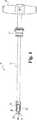
Referring now to FIG. 1, a
[0016]
Referring now to FIG. 2, the
[0017]
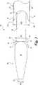
The
[0018]
The
[0019]
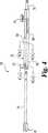
2-5, in accordance with another aspect of the present invention, a cutting instrument or
[0020]
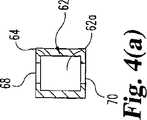
The
[0021]
The total width W 1 between the
[0022]
In one alternative shown in FIG. 4 (b), the
[0023]
In one alternative embodiment shown in FIG. 6, the
[0024]
In another embodiment shown in FIG. 7, the
[0025]
2-5, the
[0026]
The
[0027]
The
[0028]
The steps of a spinal surgical procedure according to one aspect of the present invention are illustrated in FIGS. In the illustrated process, a disc space D between adjacent vertebral bodies having a posterior side P and an anterior side A is illustrated. The skin and tissue are removed and the disc space D is accessed using any known surgical technique and instrument. In general, a hole can be created in the disc annulus at the desired entry location, and all or part of the disc nucleus can be extracted through this annulus. As shown in FIG. 8, the
[0029]
When the desired height is reached, the
[0030]
Once the implant insertion path is cut to the desired depth into the vertebral endplate, the
[0031]
Discs multiple implants through a single lateral or transaminal approach to the disc space, or through multiple entrances that simultaneously take an anterior or posterior midline approach to the disc space It is also contemplated to insert it in two directions in the gap. These insertion implants can be filled with bone growth material that supports adjacent vertebrae from two directions and facilitates fusion.
[0032]
These instruments and methods have been disclosed with reference to specific applications for creating a disc space and inserting an implant from an oblique posterior approach to the spine. However, these include for use in a variety of surgical applications and approaches including, but not limited to, single rear approach, lateral approach, other oblique approach, and forward approach. It will be appreciated that instruments and methods may be utilized or improved. These instruments also include a working channel cannula / endoscope described in US patent application Ser. No. 09 / 160,882, filed Sep. 15, 1998, which is hereby incorporated by reference in its entirety. There are also applications for laparoscopic or endoscopic procedures for the spine, such as through.
[0033]
With further reference now to FIGS. 12 and 13, another embodiment of a spinal instrument assembly having a cutter guided by a distractor is described. The assembly 150 includes a
[0034]
The
[0035]
To form a spinal instrument assembly 150, a cutting instrument or
[0036]
The
[0037]
A
[0038]
The
[0039]
Although the invention has been illustrated and described in detail in the drawings and foregoing description, it is to be considered that the invention is exemplary in character and not limiting. It should be understood that only the preferred embodiment has been shown and described, and thus protection of all variations and modifications encompassed within the spirit of the invention is desired.
[Brief description of the drawings]
FIG. 1 is a top view of a distractor assembly according to one aspect of the present invention.
2 is an enlarged top view showing the distal end of the distractor assembly of FIG. 1 and the distal end of the cutter. FIG.
FIG. 3 is a side elevational view showing the distal end of the distractor and cutter of FIG. 2;
FIG. 4 illustrates a distractor / cutter assembly according to another aspect of the present invention.
4 (a) is a cross-sectional view taken through line 4 (a) -4 (a) of FIG.
4 (b) is a cross-sectional view taken through line 4 (b) -4 (b) of FIG.
FIG. 5 is a perspective view of the distractor / cutter assembly of FIG. 4, with a handle attached to the proximal end of the cutter.
FIG. 6 is a cross-sectional view of an alternative embodiment distractor according to the present invention.
FIG. 7 is a cross-sectional view showing another embodiment of the distractor according to the present invention.
FIG. 8 is a top view of the distractor assembly of FIG. 1 inserted substantially into the disc space from the rear approach path.
FIG. 9 is a top view of the distractor / cutter assembly of FIG. 5, with the distractor in the disc gap and the cutter adjacent to the disc gap.
FIG. 10 shows the distractor / cutter assembly of FIG. 5 with the distractor and cutter in the disc gap.
FIG. 11 is an enlarged view showing the distractor and the distal end of the cutter in the disc space.
FIG. 12 is an enlarged top view showing another embodiment of the distractor and the distal end of the cutter according to the present invention.
13 is a side elevational view showing the distal end of the cutter of FIG. 12. FIG.
Claims (31)
Translated fromJapanese前記本体部の前記前端から前記後端に向かって近位方向にそれぞれ延在し、第1フランジが前記第1側壁から一定の間隔で離間し、かつ第2フランジが前記第2側壁から一定の間隔で離間する第1フランジおよび第2フランジとを備える伸延器。A body portion extending between the front end and the rear end, including a top surface and an opposing bottom surface, wherein opposing first and second sidewalls extend between the top surface and the bottom surface;
The main body portion extends in the proximal direction from the front end toward the rear end, the first flange is spaced from the first side wall at a constant interval, and the second flange is constant from the second side wall. A distractor comprising a first flange and a second flange spaced apart by an interval.
前端と後端の間に延在し、隣接する椎骨の間に延びる、対向する第1および第2側壁を含む本体部と、
それぞれが前記本体部の前記前端から前記本体部の前記後端に向かって延び、それぞれが、前記第1および第2側壁のそれぞれの1つと共に前記本体部に沿って溝穴を形成する第1フランジおよび第2フランジとを備える伸延器。A distractor for distracting a disc space between adjacent vertebral bodies,
A body portion including opposing first and second sidewalls extending between the anterior and posterior ends and extending between adjacent vertebrae;
First extending from the front end of the body portion toward the rear end of the body portion, each forming a slot along the body portion with each one of the first and second sidewalls. A distractor comprising a flange and a second flange.
前記本体部の前記前端から前記本体部の前記後端に向かって延びる第1フランジおよび第2フランジをさらに備え、前記第1および第2フランジのそれぞれが、前記第1および第2側壁のそれぞれの1つと共に前記本体部に沿って溝穴を形成する、伸延器。A vertebra that extends between an anterior end and an posterior end, includes a body portion that includes an upper surface and an opposing lower surface, with opposing first and second sidewalls extending between the upper surface and the lower surface, wherein the body portion is adjacent When inserted into the disc space between the bodies, at least a portion of the upper and lower surfaces are contactable with an end plate of an adjacent vertebral body, and the body portion is formed in the upper surface, A distractor including a cavity extending between the lower surfaces,
The main body further includes a first flange and a second flange extending from the front end of the main body toward the rear end of the main body, and each of the first and second flanges is provided on each of the first and second side walls. A distractorthat, together with one, forms a slot along the body .
それぞれが前記本体部の前記前端から前記本体部の前記後端に向かって延び、それぞれが、前記第1および第2側壁のそれぞれの1つと共に前記本体部に沿って溝穴を形成する第1フランジおよび第2フランジと、
前記本体部の前記後端から近位方向に延びる細長い柄とを含む伸延器と、
遠位切断端を有する細長い軸であって、上部材、下部材、およびそれらの間に延在する1対の側壁を含み、前記伸延器の前記本体部を収容するようにサイズ決めされた溝を画定し、それによって前記伸延器の前記本体部が軸の前記溝中にあるとき、前記側壁が前記溝穴のそれぞれの1つの中で位置決め可能である細長い軸を含む切断器具とを備える脊椎用器具組立体。A body portion including opposing first and second sidewalls extending between the front and rear ends and extending between adjacent vertebral bodies;
First extending from the front end of the body portion toward the rear end of the body portion, each forming a slot along the body portion with each one of the first and second sidewalls. A flange and a second flange;
A distractor including an elongated handle extending proximally from the rear end of the body portion;
An elongate shaft having a distal cutting end, comprising an upper member, a lower member, and a pair of sidewalls extending therebetween, sized to receive the body portion of the distractor And a cutting instrument comprising an elongated shaft that is positionable in each one of the slots when the body portion of the distractor is in the groove of the shaft. Instrument assembly.
前記下部材が、前記下部材の遠位端に形成した刃を含む、請求項17に記載の組立体。The assembly ofclaim 17 , wherein the upper member includes a blade formed at a distal end of the upper member and the lower member includes a blade formed at a distal end of the lower member.
前記軸の前記上部材および前記下部材がそれぞれ開口を画定し、その開口を介して、前記溝と連通しかつ前記空洞と位置合わせ可能である、請求項17に記載の組立体。The body portion of the distractor includes a cavity formed therethrough and extending between an upper surface and a lower surface of the body portion;
18. The assembly ofclaim 17 , wherein the upper member and the lower member of the shaft each define an opening, through which the groove communicates and can be aligned with the cavity.
遠位切断端を有する細長い軸を含み、前記軸の前記切断端が、前記伸延器と相互に嵌合するように構成されかつ前記伸延器の前記本体部を収容するような寸法の高さを備える溝を有し、前記遠位切断端が、前記第1の幅よりも広い第2の幅を有する切断器具とを備える脊椎用器具組立体であって、
前記伸延器が、
それぞれが前記本体部の前記前端から前記本体部の前記後端に向かって延び、それぞれが、前記第1および第2本体部側壁のそれぞれの1つと共に前記本体部に沿って溝穴を形成する第1フランジおよび第2フランジと、
前記本体部の前記後端から近位方向に延びる細長い柄とを含む、脊椎用器具組立体。A body portion extending between the front and rear ends, the body portion including opposing first and second sidewalls extending between adjacent vertebral bodies and having a first width between the sidewalls. A distractor having,
Including an elongated shaft having a distal cut end, the cut end of the shaft being configured to interfit with the distractor and dimensioned to receive the body portion of the distractor. A spinal instrument assembly comprising: a cutting instrument having a groove with the distal cutting end having a second widthwider than the first width;
The distractor is
Each extends from the front end of the body portion toward the rear end of the body portion, and each forms a slot along the body portion with each one of the first and second body portion sidewalls. A first flange and a second flange;
A spinal instrument assemblyincluding an elongated handle extending proximally from the rear end of the body portion .
前記軸が開口を画定し、その開口を介して、前記溝と連通しかつ前記空洞と位置合わせ可能である、請求項25に記載の組立体。The body portion of the distractor includes a cavity formed therethrough and extending between an upper surface and a lower surface of the body portion;
26. The assembly ofclaim 25 , wherein the shaft defines an opening through which the groove communicates and is alignable with the cavity.
前記切断器具が、前記軸の前記溝中に少なくとも1本の案内ピンを含み、前記案内ピンが前記案内溝穴中に滑動可能に収容されている、請求項25に記載の組立体。The body portion of the distractor includes a guide slot formed therethrough and extending generally parallel to the side wall of the body portion;
26. The assembly ofclaim 25 , wherein the cutting instrument includes at least one guide pin in the groove of the shaft, the guide pin slidably received in the guide slot.
Applications Claiming Priority (2)
| Application Number | Priority Date | Filing Date | Title |
|---|---|---|---|
| US09/692,980US6599291B1 (en) | 2000-10-20 | 2000-10-20 | Methods and instruments for interbody surgical techniques |
| PCT/US2001/042457WO2002034144A1 (en) | 2000-10-20 | 2001-10-02 | Methods and instruments for interbody surgical techniques |
Publications (2)
| Publication Number | Publication Date |
|---|---|
| JP2004512084A JP2004512084A (en) | 2004-04-22 |
| JP4018982B2true JP4018982B2 (en) | 2007-12-05 |
Family
ID=24782836
Family Applications (1)
| Application Number | Title | Priority Date | Filing Date |
|---|---|---|---|
| JP2002537200AExpired - Fee RelatedJP4018982B2 (en) | 2000-10-20 | 2001-10-02 | Methods and instruments for interbody surgery techniques |
Country Status (9)
| Country | Link |
|---|---|
| US (4) | US6599291B1 (en) |
| EP (3) | EP1468654B1 (en) |
| JP (1) | JP4018982B2 (en) |
| AT (1) | ATE298534T1 (en) |
| AU (2) | AU9697501A (en) |
| CA (1) | CA2426019A1 (en) |
| DE (2) | DE60117303T2 (en) |
| ES (2) | ES2258751T3 (en) |
| WO (1) | WO2002034144A1 (en) |
Families Citing this family (117)
| Publication number | Priority date | Publication date | Assignee | Title |
|---|---|---|---|---|
| EP0873145A2 (en) | 1996-11-15 | 1998-10-28 | Advanced Bio Surfaces, Inc. | Biomaterial system for in situ tissue repair |
| DE60104286T2 (en)* | 2000-02-22 | 2005-07-28 | SDGI Holdings, Inc., Wilmington | CUTLERY FOR PREPARING THE INTERMEDIATE ROOM |
| US6478800B1 (en) | 2000-05-08 | 2002-11-12 | Depuy Acromed, Inc. | Medical installation tool |
| US6599291B1 (en)* | 2000-10-20 | 2003-07-29 | Sdgi Holdings, Inc. | Methods and instruments for interbody surgical techniques |
| US8858564B2 (en) | 2001-02-15 | 2014-10-14 | Spinecore, Inc. | Wedge plate inserter/impactor and related methods for use in implanting an artificial intervertebral disc |
| US7575576B2 (en)* | 2001-07-16 | 2009-08-18 | Spinecore, Inc. | Wedge ramp distractor and related methods for use in implanting artificial intervertebral discs |
| US7169182B2 (en) | 2001-07-16 | 2007-01-30 | Spinecore, Inc. | Implanting an artificial intervertebral disc |
| US8940047B2 (en)* | 2001-02-15 | 2015-01-27 | Spinecore, Inc. | Intervertebral spacer device having recessed notch pairs for manipulation using a surgical tool |
| US6929647B2 (en)* | 2001-02-21 | 2005-08-16 | Howmedica Osteonics Corp. | Instrumentation and method for implant insertion |
| US20070198092A1 (en)* | 2001-07-16 | 2007-08-23 | Spinecore, Inc. | System for inserting artificial intervertebral discs |
| US7771477B2 (en)* | 2001-10-01 | 2010-08-10 | Spinecore, Inc. | Intervertebral spacer device utilizing a belleville washer having radially spaced concentric grooves |
| US6840941B2 (en)* | 2001-10-31 | 2005-01-11 | Depuy Acromed, Inc. | Vertebral endplate chisel |
| US6669699B2 (en)* | 2001-11-30 | 2003-12-30 | Spinecore, Inc. | Distraction instrument for use in anterior cervical fixation surgery |
| US20030105466A1 (en)* | 2001-11-30 | 2003-06-05 | Ralph James D. | Spacer device and insertion instrument for use in anterior cervical fixation surgery |
| US8038713B2 (en) | 2002-04-23 | 2011-10-18 | Spinecore, Inc. | Two-component artificial disc replacements |
| US20080027548A9 (en) | 2002-04-12 | 2008-01-31 | Ferree Bret A | Spacerless artificial disc replacements |
| AU2003234508A1 (en)* | 2002-05-06 | 2003-11-17 | Warsaw Orthopedic, Inc. | Instrumentation and methods for preparation of an intervertebral space |
| US6736821B2 (en)* | 2002-06-18 | 2004-05-18 | Sdgi Holdings, Inc. | System and method of mating implants and vertebral bodies |
| WO2004008976A1 (en)* | 2002-07-19 | 2004-01-29 | Osteotech, Inc. | Chisels and procedure for insertion of spinal implant in a spinal disc space |
| US7306603B2 (en) | 2002-08-21 | 2007-12-11 | Innovative Spinal Technologies | Device and method for percutaneous placement of lumbar pedicle screws and connecting rods |
| US7127857B2 (en)* | 2002-09-04 | 2006-10-31 | Connor Sports Flooring Corporation | Subfloor assembly for athletic playing surface having improved deflection characteristics |
| WO2004043271A1 (en)* | 2002-11-08 | 2004-05-27 | Sdgi Holdings, Inc. | Transpedicular intervertebral disk access methods and devices |
| US6908484B2 (en) | 2003-03-06 | 2005-06-21 | Spinecore, Inc. | Cervical disc replacement |
| WO2004086988A1 (en)* | 2003-04-04 | 2004-10-14 | Caroli, Fabrizio | Osteotom |
| US7491204B2 (en) | 2003-04-28 | 2009-02-17 | Spine Solutions, Inc. | Instruments and method for preparing an intervertebral space for receiving an artificial disc implant |
| US7655012B2 (en)* | 2003-10-02 | 2010-02-02 | Zimmer Spine, Inc. | Methods and apparatuses for minimally invasive replacement of intervertebral discs |
| US20050171608A1 (en) | 2004-01-09 | 2005-08-04 | Sdgi Holdings, Inc. | Centrally articulating spinal device and method |
| US7771479B2 (en) | 2004-01-09 | 2010-08-10 | Warsaw Orthopedic, Inc. | Dual articulating spinal device and method |
| EP1713408B1 (en) | 2004-02-09 | 2010-09-15 | DePuy Spine, Inc. | Systems for spinal surgery |
| US7641664B2 (en) | 2004-02-12 | 2010-01-05 | Warsaw Orthopedic, Inc. | Surgical instrumentation and method for treatment of a spinal structure |
| US8784421B2 (en) | 2004-03-03 | 2014-07-22 | Boston Scientific Scimed, Inc. | Apparatus and methods for removing vertebral bone and disc tissue |
| US20050209622A1 (en)* | 2004-03-03 | 2005-09-22 | Scimed Life Systems, Inc. | Tissue removal probe with irrigation and aspiration ports |
| US20050209610A1 (en) | 2004-03-03 | 2005-09-22 | Scimed Life Systems, Inc. | Radially adjustable tissue removal device |
| US20050197661A1 (en)* | 2004-03-03 | 2005-09-08 | Scimed Life Systems, Inc. | Tissue removal probe with sliding burr in cutting window |
| US7549993B2 (en)* | 2004-06-16 | 2009-06-23 | Warsaw Orthopedic, Inc. | Constant lift cam spreader |
| US20060106395A1 (en)* | 2004-07-23 | 2006-05-18 | Cervitech, Inc. | Instrument set and method for working a cervical vertebral body |
| DE102004043996B4 (en)* | 2004-09-08 | 2008-04-17 | Aesculap Ag & Co. Kg | Surgical instrument and implant system |
| US7763024B2 (en)* | 2004-09-23 | 2010-07-27 | Spine Solutions, Inc. | Adjustable cutting of cutout in vertebral bone |
| DE102004049243B4 (en)* | 2004-10-01 | 2008-07-10 | Fabrizio Dr. Caroli | Surgical instrument |
| DE102004049247A1 (en) | 2004-10-01 | 2006-04-13 | Aesculap Ag & Co. Kg | Surgical instrument |
| US7731719B2 (en)* | 2004-12-22 | 2010-06-08 | John Nordt | Safety knife for resection of annulus |
| US9072554B2 (en) | 2005-09-21 | 2015-07-07 | Children's Hospital Medical Center | Orthopedic implant |
| US20070123904A1 (en)* | 2005-10-31 | 2007-05-31 | Depuy Spine, Inc. | Distraction instrument and method for distracting an intervertebral site |
| US7867237B2 (en)* | 2005-10-31 | 2011-01-11 | Depuy Spine, Inc. | Arthroplasty revision device and method |
| US20070123903A1 (en)* | 2005-10-31 | 2007-05-31 | Depuy Spine, Inc. | Medical Device installation tool and methods of use |
| US7988695B2 (en) | 2005-12-21 | 2011-08-02 | Theken Spine, Llc | Articulated delivery instrument |
| US7635389B2 (en)* | 2006-01-30 | 2009-12-22 | Warsaw Orthopedic, Inc. | Posterior joint replacement device |
| US7811326B2 (en) | 2006-01-30 | 2010-10-12 | Warsaw Orthopedic Inc. | Posterior joint replacement device |
| US7766918B2 (en)* | 2006-01-31 | 2010-08-03 | Warsaw Orthopedic, Inc. | Spinal disc replacement surgical instrument and methods for use in spinal disc replacement |
| US8377072B2 (en)* | 2006-02-06 | 2013-02-19 | Depuy Spine, Inc. | Medical device installation tool |
| US7520888B2 (en) | 2006-02-14 | 2009-04-21 | Warsaw Orthopedic, Inc. | Treatment of the vertebral column |
| US8876687B2 (en) | 2006-03-08 | 2014-11-04 | Zimmer Spine, Inc. | Surgical retractor and retractor assembly |
| US7875034B2 (en)* | 2006-03-14 | 2011-01-25 | Warsaw Orthopedic, Inc. | Spinal disc space preparation instruments and methods for interbody spinal implants |
| US7976549B2 (en)* | 2006-03-23 | 2011-07-12 | Theken Spine, Llc | Instruments for delivering spinal implants |
| US20070270862A1 (en)* | 2006-03-30 | 2007-11-22 | Sdgi Holdings, Inc. | Instruments and methods for preparing an intervertebral space |
| US20070276491A1 (en)* | 2006-05-24 | 2007-11-29 | Disc Dynamics, Inc. | Mold assembly for intervertebral prosthesis |
| US8092536B2 (en) | 2006-05-24 | 2012-01-10 | Disc Dynamics, Inc. | Retention structure for in situ formation of an intervertebral prosthesis |
| US8303601B2 (en) | 2006-06-07 | 2012-11-06 | Stryker Spine | Collet-activated distraction wedge inserter |
| EP3628244A1 (en) | 2006-07-24 | 2020-04-01 | Centinel Spine Schweiz GmbH | Intervertebral implant with keel |
| BRPI0714955A2 (en) | 2006-07-31 | 2013-07-23 | Systhes Gmbh | instrument system and method for preparing an intervertebral space to receive an implant, and milling guide for use with an instrument system |
| US8506636B2 (en) | 2006-09-08 | 2013-08-13 | Theken Spine, Llc | Offset radius lordosis |
| WO2008070863A2 (en) | 2006-12-07 | 2008-06-12 | Interventional Spine, Inc. | Intervertebral implant |
| EP2114257B1 (en)* | 2007-02-09 | 2013-05-22 | Alphatec Spine, Inc. | Curvilinear spinal access device |
| US8864832B2 (en)* | 2007-06-20 | 2014-10-21 | Hh Spinal Llc | Posterior total joint replacement |
| US10821003B2 (en) | 2007-06-20 | 2020-11-03 | 3Spline Sezc | Spinal osteotomy |
| US8900307B2 (en) | 2007-06-26 | 2014-12-02 | DePuy Synthes Products, LLC | Highly lordosed fusion cage |
| US8864829B1 (en) | 2007-07-02 | 2014-10-21 | Theken Spine, Llc | Spinal cage having deployable member |
| US12186201B2 (en) | 2007-07-02 | 2025-01-07 | Theken Spine, Llc | Spinal cage having deployable member |
| US10342674B2 (en) | 2007-07-02 | 2019-07-09 | Theken Spine, Llc | Spinal cage having deployable member |
| US8545562B1 (en) | 2007-07-02 | 2013-10-01 | Theken Spine, Llc | Deployable member for use with an intervertebral cage |
| US8142508B1 (en) | 2007-07-02 | 2012-03-27 | Theken Spine, Llc | Spinal cage having deployable member which is removable |
| US8292958B1 (en) | 2007-07-02 | 2012-10-23 | Theken Spine, Llc | Spinal cage having deployable member |
| US8267997B2 (en) | 2007-11-12 | 2012-09-18 | Theken Spine, Llc | Vertebral interbody compression implant |
| EP2237748B1 (en) | 2008-01-17 | 2012-09-05 | Synthes GmbH | An expandable intervertebral implant |
| US8449554B2 (en) | 2008-03-07 | 2013-05-28 | K2M, Inc. | Intervertebral implant and instrument with removable section |
| US8936641B2 (en) | 2008-04-05 | 2015-01-20 | DePuy Synthes Products, LLC | Expandable intervertebral implant |
| US8147499B2 (en)* | 2008-04-24 | 2012-04-03 | Spinecore, Inc. | Dynamic distractor |
| EP2337510B1 (en) | 2008-06-25 | 2018-10-31 | Stryker European Holdings I, LLC | Surgical instrumentation for implanting a prothesis |
| US8382767B2 (en)* | 2008-10-31 | 2013-02-26 | K2M, Inc. | Implant insertion tool |
| US9526620B2 (en) | 2009-03-30 | 2016-12-27 | DePuy Synthes Products, Inc. | Zero profile spinal fusion cage |
| CN102448379B (en) | 2009-04-03 | 2014-11-19 | 米切尔·A·哈登布鲁克 | Surgical retractor system |
| ES2563172T3 (en) | 2009-07-09 | 2016-03-11 | R Tree Innovations, Llc | Flexible intersomatic implant |
| US8382840B2 (en)* | 2009-09-03 | 2013-02-26 | Zimmer Spine, Inc. | Spinal implant delivery methods and devices |
| US9028553B2 (en) | 2009-11-05 | 2015-05-12 | DePuy Synthes Products, Inc. | Self-pivoting spinal implant and associated instrumentation |
| US9393129B2 (en) | 2009-12-10 | 2016-07-19 | DePuy Synthes Products, Inc. | Bellows-like expandable interbody fusion cage |
| US8979860B2 (en) | 2010-06-24 | 2015-03-17 | DePuy Synthes Products. LLC | Enhanced cage insertion device |
| US9907560B2 (en) | 2010-06-24 | 2018-03-06 | DePuy Synthes Products, Inc. | Flexible vertebral body shavers |
| US8623091B2 (en) | 2010-06-29 | 2014-01-07 | DePuy Synthes Products, LLC | Distractible intervertebral implant |
| US9402732B2 (en) | 2010-10-11 | 2016-08-02 | DePuy Synthes Products, Inc. | Expandable interspinous process spacer implant |
| US9358122B2 (en) | 2011-01-07 | 2016-06-07 | K2M, Inc. | Interbody spacer |
| EP3485851B1 (en) | 2011-03-22 | 2021-08-25 | DePuy Synthes Products, LLC | Universal trial for lateral cages |
| US8795167B2 (en) | 2011-11-15 | 2014-08-05 | Baxano Surgical, Inc. | Spinal therapy lateral approach access instruments |
| US9463052B2 (en) | 2012-01-12 | 2016-10-11 | Integrity Implants Inc. | Access assembly for anterior and lateral spinal procedures |
| US9226764B2 (en) | 2012-03-06 | 2016-01-05 | DePuy Synthes Products, Inc. | Conformable soft tissue removal instruments |
| US10022245B2 (en) | 2012-12-17 | 2018-07-17 | DePuy Synthes Products, Inc. | Polyaxial articulating instrument |
| US9717601B2 (en) | 2013-02-28 | 2017-08-01 | DePuy Synthes Products, Inc. | Expandable intervertebral implant, system, kit and method |
| US9522070B2 (en) | 2013-03-07 | 2016-12-20 | Interventional Spine, Inc. | Intervertebral implant |
| US9730802B1 (en) | 2014-01-14 | 2017-08-15 | Nuvasive, Inc. | Spinal fusion implant and related methods |
| ES2948036T3 (en) | 2014-02-18 | 2023-08-30 | Alcon Inc | Apparatus for resection of an intraocular lens |
| US11426290B2 (en) | 2015-03-06 | 2022-08-30 | DePuy Synthes Products, Inc. | Expandable intervertebral implant, system, kit and method |
| US10058350B2 (en) | 2015-09-24 | 2018-08-28 | Integrity Implants, Inc. | Access assembly for anterior and lateral spinal procedures |
| EP3474784A2 (en) | 2016-06-28 | 2019-05-01 | Eit Emerging Implant Technologies GmbH | Expandable and angularly adjustable intervertebral cages with articulating joint |
| US11510788B2 (en) | 2016-06-28 | 2022-11-29 | Eit Emerging Implant Technologies Gmbh | Expandable, angularly adjustable intervertebral cages |
| AU2017340607B2 (en) | 2016-10-05 | 2022-10-27 | Nuvasive, Inc. | Surgical navigation system and related methods |
| US10398563B2 (en) | 2017-05-08 | 2019-09-03 | Medos International Sarl | Expandable cage |
| US11344424B2 (en) | 2017-06-14 | 2022-05-31 | Medos International Sarl | Expandable intervertebral implant and related methods |
| US10966843B2 (en) | 2017-07-18 | 2021-04-06 | DePuy Synthes Products, Inc. | Implant inserters and related methods |
| US11045331B2 (en) | 2017-08-14 | 2021-06-29 | DePuy Synthes Products, Inc. | Intervertebral implant inserters and related methods |
| US11013607B2 (en) | 2017-09-22 | 2021-05-25 | Encore Medical, L.P. | Talar ankle implant |
| EP3501432A1 (en) | 2017-12-20 | 2019-06-26 | Stryker European Holdings I, LLC | Joint instrumentation |
| US11446156B2 (en) | 2018-10-25 | 2022-09-20 | Medos International Sarl | Expandable intervertebral implant, inserter instrument, and related methods |
| US11612440B2 (en) | 2019-09-05 | 2023-03-28 | Nuvasive, Inc. | Surgical instrument tracking devices and related methods |
| US11426286B2 (en) | 2020-03-06 | 2022-08-30 | Eit Emerging Implant Technologies Gmbh | Expandable intervertebral implant |
| US11850160B2 (en) | 2021-03-26 | 2023-12-26 | Medos International Sarl | Expandable lordotic intervertebral fusion cage |
| US11752009B2 (en) | 2021-04-06 | 2023-09-12 | Medos International Sarl | Expandable intervertebral fusion cage |
| US12090064B2 (en) | 2022-03-01 | 2024-09-17 | Medos International Sarl | Stabilization members for expandable intervertebral implants, and related systems and methods |
| US12409046B2 (en) | 2022-04-12 | 2025-09-09 | 3Spine, Inc. | Total spinal joint systems with motion moderators |
Family Cites Families (35)
| Publication number | Priority date | Publication date | Assignee | Title |
|---|---|---|---|---|
| US3486505A (en) | 1967-05-22 | 1969-12-30 | Gordon M Morrison | Orthopedic surgical instrument |
| US3848601A (en) | 1972-06-14 | 1974-11-19 | G Ma | Method for interbody fusion of the spine |
| US4059115A (en) | 1976-06-14 | 1977-11-22 | Georgy Stepanovich Jumashev | Surgical instrument for operation of anterior fenestrated spondylodessis in vertebral osteochondrosis |
| EP0077159A1 (en) | 1981-10-14 | 1983-04-20 | Brian Norman Atkins | Vertebrae spreader |
| US4743256A (en) | 1985-10-04 | 1988-05-10 | Brantigan John W | Surgical prosthetic implant facilitating vertebral interbody fusion and method |
| US5484437A (en) | 1988-06-13 | 1996-01-16 | Michelson; Gary K. | Apparatus and method of inserting spinal implants |
| US5772661A (en) | 1988-06-13 | 1998-06-30 | Michelson; Gary Karlin | Methods and instrumentation for the surgical correction of human thoracic and lumbar spinal disease from the antero-lateral aspect of the spine |
| US5423825A (en) | 1992-06-10 | 1995-06-13 | Levine; Andrew S. | Spinal fusion instruments and methods |
| CA2155422C (en) | 1993-02-10 | 2005-07-12 | Stephen D. Kuslich | Spinal stabilization surgical method |
| DE4328690B4 (en) | 1993-08-26 | 2006-08-17 | SDGI Holdings, Inc., Wilmington | Intervertebral implant for vertebral body blocking and implantation instrument for positioning the intervertebral implant |
| CN1156255C (en)* | 1993-10-01 | 2004-07-07 | 美商-艾克罗米德公司 | Spinal implant |
| US5431658A (en) | 1994-02-14 | 1995-07-11 | Moskovich; Ronald | Facilitator for vertebrae grafts and prostheses |
| US5766252A (en)* | 1995-01-24 | 1998-06-16 | Osteonics Corp. | Interbody spinal prosthetic implant and method |
| US5722977A (en) | 1996-01-24 | 1998-03-03 | Danek Medical, Inc. | Method and means for anterior lumbar exact cut with quadrilateral osteotome and precision guide/spacer |
| CA2199462C (en) | 1996-03-14 | 2006-01-03 | Charles J. Winslow | Method and instrumentation for implant insertion |
| US5700264A (en)* | 1996-07-01 | 1997-12-23 | Zucherman; James F. | Apparatus and method for preparing a site for an interbody fusion implant |
| WO1998017208A2 (en) | 1996-10-22 | 1998-04-30 | Surgical Dynamics, Inc. | Apparatus for fusing adjacent bone structures |
| TW375522B (en) | 1996-10-24 | 1999-12-01 | Danek Medical Inc | Devices for percutaneous surgery under direct visualization and through an elongated cannula |
| US6190414B1 (en)* | 1996-10-31 | 2001-02-20 | Surgical Dynamics Inc. | Apparatus for fusion of adjacent bone structures |
| WO1998042269A1 (en) | 1997-03-24 | 1998-10-01 | Haider Thomas T | Spinal immobilization device and method |
| US6045579A (en) | 1997-05-01 | 2000-04-04 | Spinal Concepts, Inc. | Adjustable height fusion device |
| US6042582A (en) | 1997-05-20 | 2000-03-28 | Ray; Charles D. | Instrumentation and method for facilitating insertion of spinal implant |
| WO1999007312A1 (en)* | 1997-08-06 | 1999-02-18 | Synthes Ag Chur | Intervertebral implant whereof the parts can be spaced |
| US6004326A (en) | 1997-09-10 | 1999-12-21 | United States Surgical | Method and instrumentation for implant insertion |
| US6021343A (en) | 1997-11-20 | 2000-02-01 | Surgical Navigation Technologies | Image guided awl/tap/screwdriver |
| US6428541B1 (en)* | 1998-04-09 | 2002-08-06 | Sdgi Holdings, Inc. | Method and instrumentation for vertebral interbody fusion |
| US6197033B1 (en)* | 1998-04-09 | 2001-03-06 | Sdgi Holdings, Inc. | Guide sleeve for offset vertebrae |
| ATE274844T1 (en) | 1998-04-09 | 2004-09-15 | Sdgi Holdings Inc | VERTEBRATE BODY DISTRACTOR |
| US6290724B1 (en)* | 1998-05-27 | 2001-09-18 | Nuvasive, Inc. | Methods for separating and stabilizing adjacent vertebrae |
| US6083228A (en) | 1998-06-09 | 2000-07-04 | Michelson; Gary K. | Device and method for preparing a space between adjacent vertebrae to receive an insert |
| US6126664A (en) | 1999-01-19 | 2000-10-03 | Synthes (Usa) | Device and method for locating and resecting bone |
| ATE464847T1 (en) | 1999-01-25 | 2010-05-15 | Warsaw Orthopedic Inc | INSTRUMENT FOR CREATION OF AN INTERVERBEL SPACE FOR ACCOMMODATION OF AN IMPLANT |
| AU761818C (en) | 1999-02-04 | 2004-05-27 | Warsaw Orthopedic, Inc. | Methods and instrumentation for vertebral interbody fusion |
| US6641582B1 (en)* | 2000-07-06 | 2003-11-04 | Sulzer Spine-Tech Inc. | Bone preparation instruments and methods |
| US6599291B1 (en)* | 2000-10-20 | 2003-07-29 | Sdgi Holdings, Inc. | Methods and instruments for interbody surgical techniques |
- 2000
- 2000-10-20USUS09/692,980patent/US6599291B1/ennot_activeExpired - Fee Related
- 2001
- 2001-10-02CACA002426019Apatent/CA2426019A1/ennot_activeAbandoned
- 2001-10-02WOPCT/US2001/042457patent/WO2002034144A1/enactiveIP Right Grant
- 2001-10-02ESES04016240Tpatent/ES2258751T3/ennot_activeExpired - Lifetime
- 2001-10-02EPEP04016240Apatent/EP1468654B1/ennot_activeExpired - Lifetime
- 2001-10-02DEDE60117303Tpatent/DE60117303T2/ennot_activeExpired - Fee Related
- 2001-10-02JPJP2002537200Apatent/JP4018982B2/ennot_activeExpired - Fee Related
- 2001-10-02ESES01977891Tpatent/ES2243565T3/ennot_activeExpired - Lifetime
- 2001-10-02AUAU9697501Apatent/AU9697501A/enactivePending
- 2001-10-02DEDE60111763Tpatent/DE60111763T2/ennot_activeExpired - Fee Related
- 2001-10-02ATAT01977891Tpatent/ATE298534T1/ennot_activeIP Right Cessation
- 2001-10-02EPEP04016241Apatent/EP1466562A1/ennot_activeWithdrawn
- 2001-10-02EPEP01977891Apatent/EP1328200B1/ennot_activeExpired - Lifetime
- 2001-10-02AUAU2001296975Apatent/AU2001296975B2/ennot_activeCeased
- 2003
- 2003-07-23USUS10/625,418patent/US7169152B2/ennot_activeExpired - Lifetime
- 2006
- 2006-12-20USUS11/642,405patent/US7803161B2/ennot_activeExpired - Lifetime
- 2010
- 2010-08-26USUS12/807,027patent/US8142438B2/ennot_activeExpired - Fee Related
Also Published As
| Publication number | Publication date |
|---|---|
| US8142438B2 (en) | 2012-03-27 |
| DE60117303T2 (en) | 2006-11-02 |
| US20040220581A1 (en) | 2004-11-04 |
| EP1468654A1 (en) | 2004-10-20 |
| DE60111763T2 (en) | 2005-12-15 |
| EP1328200B1 (en) | 2005-06-29 |
| DE60111763D1 (en) | 2005-08-04 |
| US20100331845A1 (en) | 2010-12-30 |
| CA2426019A1 (en) | 2002-05-02 |
| US7169152B2 (en) | 2007-01-30 |
| EP1468654B1 (en) | 2006-02-15 |
| ATE298534T1 (en) | 2005-07-15 |
| US6599291B1 (en) | 2003-07-29 |
| WO2002034144A9 (en) | 2002-07-18 |
| AU2001296975B2 (en) | 2004-09-23 |
| US20070123901A1 (en) | 2007-05-31 |
| JP2004512084A (en) | 2004-04-22 |
| EP1328200A1 (en) | 2003-07-23 |
| WO2002034144A1 (en) | 2002-05-02 |
| DE60117303D1 (en) | 2006-04-20 |
| EP1466562A1 (en) | 2004-10-13 |
| ES2258751T3 (en) | 2006-09-01 |
| US7803161B2 (en) | 2010-09-28 |
| ES2243565T3 (en) | 2005-12-01 |
| AU9697501A (en) | 2002-05-06 |
Similar Documents
| Publication | Publication Date | Title |
|---|---|---|
| JP4018982B2 (en) | Methods and instruments for interbody surgery techniques | |
| JP4326134B2 (en) | Method and apparatus for performing a surgical procedure | |
| AU2001296975A1 (en) | Methods and instruments for interbody surgical techniques | |
| US6042582A (en) | Instrumentation and method for facilitating insertion of spinal implant | |
| EP2012674B1 (en) | Monorail system for use in spinal fusion surgery | |
| US8597299B2 (en) | Instrumentation and method for providing surgical access to a spine | |
| CA2199462C (en) | Method and instrumentation for implant insertion | |
| US6719760B2 (en) | Devices and methods for implanting fusion cages | |
| JP2002540882A (en) | Spinal implant insertion method and instrument |
Legal Events
| Date | Code | Title | Description |
|---|---|---|---|
| A621 | Written request for application examination | Free format text:JAPANESE INTERMEDIATE CODE: A621 Effective date:20040629 | |
| A711 | Notification of change in applicant | Free format text:JAPANESE INTERMEDIATE CODE: A712 Effective date:20061011 | |
| A131 | Notification of reasons for refusal | Free format text:JAPANESE INTERMEDIATE CODE: A131 Effective date:20070206 | |
| A601 | Written request for extension of time | Free format text:JAPANESE INTERMEDIATE CODE: A601 Effective date:20070207 | |
| A602 | Written permission of extension of time | Free format text:JAPANESE INTERMEDIATE CODE: A602 Effective date:20070215 | |
| A521 | Request for written amendment filed | Free format text:JAPANESE INTERMEDIATE CODE: A523 Effective date:20070806 | |
| TRDD | Decision of grant or rejection written | ||
| A01 | Written decision to grant a patent or to grant a registration (utility model) | Free format text:JAPANESE INTERMEDIATE CODE: A01 Effective date:20070830 | |
| A61 | First payment of annual fees (during grant procedure) | Free format text:JAPANESE INTERMEDIATE CODE: A61 Effective date:20070921 | |
| R150 | Certificate of patent or registration of utility model | Free format text:JAPANESE INTERMEDIATE CODE: R150 | |
| FPAY | Renewal fee payment (event date is renewal date of database) | Free format text:PAYMENT UNTIL: 20100928 Year of fee payment:3 | |
| FPAY | Renewal fee payment (event date is renewal date of database) | Free format text:PAYMENT UNTIL: 20110928 Year of fee payment:4 | |
| LAPS | Cancellation because of no payment of annual fees |