JP4017894B2 - IMAGING DEVICE, ITS ASSEMBLY METHOD, AND IMAGING SYSTEM - Google Patents
IMAGING DEVICE, ITS ASSEMBLY METHOD, AND IMAGING SYSTEMDownload PDFInfo
- Publication number
- JP4017894B2 JP4017894B2JP2002070052AJP2002070052AJP4017894B2JP 4017894 B2JP4017894 B2JP 4017894B2JP 2002070052 AJP2002070052 AJP 2002070052AJP 2002070052 AJP2002070052 AJP 2002070052AJP 4017894 B2JP4017894 B2JP 4017894B2
- Authority
- JP
- Japan
- Prior art keywords
- lens
- reference surface
- pair
- assembly
- housing
- Prior art date
- Legal status (The legal status is an assumption and is not a legal conclusion. Google has not performed a legal analysis and makes no representation as to the accuracy of the status listed.)
- Expired - Fee Related
Links
- 238000003384imaging methodMethods0.000titleclaimsdescription104
- 238000000034methodMethods0.000titleclaimsdescription35
- 230000003287optical effectEffects0.000claimsdescription52
- 230000007246mechanismEffects0.000claimsdescription10
- 238000005452bendingMethods0.000claimsdescription2
- 230000014759maintenance of locationEffects0.000claims1
- 230000000694effectsEffects0.000description3
- 230000001154acute effectEffects0.000description2
- 238000001514detection methodMethods0.000description2
- 239000000463materialSubstances0.000description2
- 239000004033plasticSubstances0.000description2
- 229920000305Nylon 6,10Polymers0.000description1
- 230000002411adverseEffects0.000description1
- 230000000712assemblyEffects0.000description1
- 238000000429assemblyMethods0.000description1
- 230000005540biological transmissionEffects0.000description1
- 230000000994depressogenic effectEffects0.000description1
- 238000005516engineering processMethods0.000description1
- 238000001746injection mouldingMethods0.000description1
- 238000012634optical imagingMethods0.000description1
- 239000004417polycarbonateSubstances0.000description1
- 229920000515polycarbonatePolymers0.000description1
- 238000005070samplingMethods0.000description1
- 229910001220stainless steelInorganic materials0.000description1
- 239000010935stainless steelSubstances0.000description1
- 238000010408sweepingMethods0.000description1
Images


Classifications
- H—ELECTRICITY
- H04—ELECTRIC COMMUNICATION TECHNIQUE
- H04N—PICTORIAL COMMUNICATION, e.g. TELEVISION
- H04N1/00—Scanning, transmission or reproduction of documents or the like, e.g. facsimile transmission; Details thereof
- H04N1/024—Details of scanning heads ; Means for illuminating the original
- H04N1/028—Details of scanning heads ; Means for illuminating the original for picture information pick-up
- H04N1/03—Details of scanning heads ; Means for illuminating the original for picture information pick-up with photodetectors arranged in a substantially linear array
- H—ELECTRICITY
- H04—ELECTRIC COMMUNICATION TECHNIQUE
- H04N—PICTORIAL COMMUNICATION, e.g. TELEVISION
- H04N2201/00—Indexing scheme relating to scanning, transmission or reproduction of documents or the like, and to details thereof
- H04N2201/024—Indexing scheme relating to scanning, transmission or reproduction of documents or the like, and to details thereof deleted
- H04N2201/02406—Arrangements for positioning elements within a head
- H04N2201/02427—Element positioned
- H04N2201/02431—Lens or optical system
- H—ELECTRICITY
- H04—ELECTRIC COMMUNICATION TECHNIQUE
- H04N—PICTORIAL COMMUNICATION, e.g. TELEVISION
- H04N2201/00—Indexing scheme relating to scanning, transmission or reproduction of documents or the like, and to details thereof
- H04N2201/024—Indexing scheme relating to scanning, transmission or reproduction of documents or the like, and to details thereof deleted
- H04N2201/02406—Arrangements for positioning elements within a head
- H04N2201/02439—Positioning method
- H04N2201/02449—Positioning method using a reference element, e.g. a stop
Landscapes
- Engineering & Computer Science (AREA)
- Multimedia (AREA)
- Signal Processing (AREA)
- Studio Devices (AREA)
- Facsimile Heads (AREA)
- Lens Barrels (AREA)
Description
Translated fromJapanese【0001】
【発明の属する技術分野】
本発明は、概して撮像システムに関し、より具体的には、光センサおよび少なくとも1つのレンズが付属するタイプの撮像システムに関する。
【0002】
【従来の技術】
印刷文のページなどの対象物の画像を表す機械で読取可能なデータを生成するために、撮像装置が使用される。1つのタイプの撮像装置は、光電撮像装置である。本明細書で使用されるとき、「光電撮像装置」という言葉は、電荷結合素子(CCD)などの光センサ・アレイを使用することによって撮像対象物を表すデータを生成する任意の装置を意味する。光電撮像装置の例には、2次元光センサ・アレイ上に捕捉される画像全体の焦点を瞬時に合わせるカメラ付きビデオ装置やディジタル・カメラなどの装置がある。光電撮像装置のもう1つの例は、線状焦点システム(line−focus system)である。
【0003】
いくつかの線状焦点システムは、対象物上で走査ヘッドを掃引してリニア光センサ・アレイ上に対象物の幅の狭い「走査線」部分の焦点を順次合わせることによって対象物を撮像する。一般に光学スキャナと呼ばれるそのような装置の例には、通常単に「スキャナ」と呼ばれるコンピュータ入力装置ならびにファクシミリ装置やディジタル複写機がある。
【0004】
線状焦点システムは、また、いくつかのバーコード・リーダにも使用されている。一般に、線状焦点バーコード・リーダにおいて、バーコードの狭い部分が、リニア光センサ・アレイ上に結像される。次に、光センサ・アレイからの電気出力を解析して撮像バーコードを読み取ることができる。バーコード・リーダと組み合わせて使用可能な撮像装置の例は、「撮像装置で焦点を設定する方法および装置(METHOD AND APPARATUS FOR SETTING FOCUS IN AN IMAGING DEVICE)」に関するGardner,Jrによる米国特許第6,118,598号と、「撮像システム用の位置合わせ装置および方法(ALIGNMENT APPARATUS AND METHOD FOR AN IMAGING SYSTEM)」に関して1999年4月13日に出願されたGardner,Jrによる米国特許出願番号09/290,216に開示されており、これらは両方とも、開示されているすべての事柄に関して参照により本明細書に組み込まれる。
【0005】
線状焦点システムにおいて、照らされた線対象物からの光ビームは、レンズによって、線対象物から遠くに配置されたリニア光センサ・アレイ上に結像される。リニア光センサ・アレイは、線対象物上の小さい領域位置に対応する光素子の一次元アレイである。線対象物上のそのような小さい領域は、一般に、「画素」または「ピクセル」と呼ばれる。線対象物上のその対応する画素位置からの光に応じて、リニア光センサ・アレイ内の各光センサ画素要素(単に「ピクセル」と呼ばれることもある)は、サンプリング間隔として知られる直前の時間間隔中に受けた光強度を表すデータ信号を生成する。光素子のデータ信号はすべて、適切なデータ処理システムによって受け取られ処理される。
【0006】
カラー光学スキャナでは、スペクトル的に分離された複数の撮像ビーム(一般に、赤、緑および青のビーム)を光センサ・アレイ上に投影しなければならない。カラー光学スキャナの構造および動作は、「色結合器および色分離器ならびにその実現(COLOR COMBINER AND SEPARATOR AND IMPLEMENTATIONS)」に関するVincentらによる米国特許第4,870,268号、「光学スキャナ(OPTICAL SCANNER)」に関するBoydによる米国特許第4,926,041号(および、これに対応するEPO特許第0410578号)、「鏡取付け閉鎖アパーチャまたはフィルタを備えた光学スキャナ(OPTICAL SCANNER WITH MIRROR MOUNTED OCCLUDING APERTURE ORFILTER)」に関するBoydらによる米国特許第5,019,703号(および、対応するEPO特許第0438868号)、「画像焦点と位置決めが調整可能なビーム・スプリッタ(BEAM SPLITTER APPARATUS WITH ADJUSTABLE IMAGE FOCUS AND REGISTRATION)」に関するBoydらによる米国特許第5,032,004号(および対応するEPO特許第0458492号)、「ビーム・スプリッタ/結合器装置(BEAM SPLITTER/COMBINER APPARATUS)」に関するSteinleによる米国特許第5,044,727号(および、対応するEPO特許第0455450号)、「経路長補償装置を備えたビーム・スプリッタ/結合器(BEAM SPLITTER/COMBINER WITH PATH LENGTH COMPENSATOR)に関するSteinleによる米国特許第5,040,872号、「カラー光学スキャナの構成要素を組み立てる装置(APPARATUS FOR ASSEMBLING COMPONENTS OF COLOR OPTICAL SCANNERS)」に関するElder,Jrらによる米国特許第5,227,620号(および、対応するEPO特許第0576788)、「画像位置決め保持アセンブリを有するカラー光学スキャナ(COLOR OPTICAL SCANNERWITH IMAGE REGISTRATION HOLDING ASSEMBLY)」に関するSteinleらによる米国特許第5,410,347号に詳しく開示されており、これらの特許はすべて、開示されているすべての事柄に関して、参照により本明細書に具体的に組み込まれる。
【0007】
撮像装置、特に前述のような線状焦点型の撮像装置では、正確に撮像するために、対象物からの光ビームを光センサ・アレイと正確に位置合わせすることが好ましい。代表的な線状焦点走査装置では、撮像光ビームは、光センサ・アレイに達するまでに、1つまたは複数の光学部品(例えば、レンズ)によって送られてくる。そのような光学部品と光センサ・アレイとの間のずれがわずかであっても、光ビームと光センサ・アレイとの間に大きな位置ずれが生じ、その結果、それに対応して画像品質が低下することがある。
【0008】
光ビーム・アライメント機能を含む走査装置は、「ビーム方向操縦機能を備えた撮像装置(IMAGING DEVICE WITH BEAM STEERING CAPABILITY)」に関するSteinleらによる米国特許第5,646,394号と、「光電撮像方法および装置(PHOTOELECTRIC IMAGING METHOD AND APPARATUS)」に関するChristensenによる米国特許第6,147,343号に詳しく記載されており、これらは両方とも、開示されたすべての事柄に関して参照により本明細書に具体的に組み込まれる。
【0009】
一般に、撮像装置の光学部品は、撮像装置ハウジング内に取り付けられる。光センサ・アレイは、一般に、撮像装置ハウジングに取り付けられた回路基板に取り付けられる。また、一般に、撮像装置ハウジング内に、レンズが取り付けられる。このレンズは、光センサ・アレイ上に対象物の像の焦点を結ぶはたらきをする。撮像装置が適切に機能するためには、レンズの焦点を正確に設定しなければならない。
【0010】
撮像装置が組み立てられた後で、一般に、レンズの焦点が調整される。典型的には、これは、レンズと光センサ・アレイとの間の距離、すなわち光学系の像距離を、焦点が適切になるまで調整することによって行われる。これを達成するために、レンズを配置するための1つまたは複数の基準面を有する撮像装置が提供されることが通例である。そのような基準面は、一般に、レンズが、1つの移動度だけ、すなわち光センサに近づく方向または離れる方向にだけ平行移動することを可能にし、レンズが、他の方向にずれるのを防ぐ。そのようなずれの発生が許容されたならば、そのずれにより、レンズの位置が光センサ・アレイに対してずれることになる。したがって、基準面は、レンズと光センサ・アレイとの間のアライメントを維持しながらレンズの焦点を調整することを可能にする。以上概略的に述べたレンズの基準面は、例えば、円筒状の面またはV字型の溝の形をとる。
【0011】
また、撮像装置は、典型的には、撮像システムの焦点を設定した後でレンズを基準面に対して適所にロックするブラケットやその他の保持機構を含む。ブラケットは、例えば、ねじによって固定される。したがって、ねじは、システムの焦点を合わせるためにレンズを移動させたいときに緩められ、適切な焦点を達成したときにレンズを適所にロックするために締められる。
【0012】
【発明が解決しようとする課題】
従来の保持機構は、合焦操作中にしばしばレンズの位置ずれを引き起こすという点で問題があることが分かっている。例えば、前述のねじ保持ブラケットの場合、合焦操作の前にねじを緩めすぎると、レンズが基準面から回転して離れることが可能となり、それによりずれが生じる可能性がある。また、合焦操作が完了した後でレンズをロックするためにねじを十分に締め付けることができないことがある。その結果、レンズをロックした後でも、レンズが、その合焦位置からずれることがある。さらに、保持ねじを締め付けるために加えるトルクがレンズに伝わり、それにより、レンズが回転してアライメントがずれることがあることが分かった。
【0013】
また、従来の保持機構は、一般に撮像装置において焦点を設定するために使用されるような自動焦点調整装置による調整には適するわけではないことが分かった。
【0014】
したがって、装置内の光センサ・アレイと他の光学部品との間の正確なアライメントを実現する光学撮像装置を提供することが望ましい。
【0015】
【課題を解決するための手段】
撮像された対象物を表す機械で読取が可能なデータを生成する撮像装置を開示する。この撮像装置は、撮像装置ハウジングを含むことができ、この撮像装置ハウジングは、少なくとも1つの第1の基準面と少なくとも1つの第2の基準面とを含む。少なくとも1つの第1の基準面は、少なくとも1つの第2の基準面と同一平面上にある。少なくとも1つの第1の基準面は、少なくとも1つの第2の基準面と不連続である。少なくとも1つのレンズ・アセンブリは、少なくとも1つの第1の基準面および少なくとも1つの第2の基準面の両方と接触し得る。
【0016】
また、撮像対象物を表す機械で読取可能なデータを生成する撮像装置を組み立てる方法を開示する。この方法は、少なくとも1つの第1の基準面と少なくとも1つの第2の基準面とを有する撮像装置ハウジングを準備する段階と、少なくとも1つのレンズを準備する段階とを含むことができる。少なくとも1つの第1の基準面は、少なくとも1つの第2の基準面と同一平面上にある。また、少なくとも1つの第1の基準面は、少なくとも1つの第2の基準面と不連続である。この方法は、さらに、少なくとも1つの第1の基準面と少なくとも1つの第2の基準面とを使用して、レンズを撮像装置ハウジングと位置合わせする段階を含む。
【0017】
【発明の実施の形態】
本明細書では、例えば光センサ・アレイを含むタイプの撮像システムのための改良したレンズ合焦および保持機構を開示する。レンズは、撮像システムのハウジング内に形成された基準面と接触した状態で、かつ撮像システムの焦点を調整するために光センサ・アレイに近づく方向およびそれから遠ざかる方向において基準面に沿って平行移動可能である。
【0018】
基準面は、その端部の近くでのみレンズと接触するように構成することができる。これを達成するために、レンズの中央の近くに凹状領域を設けることができる。接触をレンズの外側部分に制限することによって、普通ならば基準面内の凹凸がアライメントに与える可能性のある影響が最小化される。
【0019】
撮像システム・ハウジング内にレンズを固定するために、レンズ保持クリップを設けることができる。レンズ保持クリップは、合焦操作中にレンズを並進させている間静止したままにすることができる。所望の焦点を達成した後で、レンズ保持クリップが塑性変形してレンズを所望の位置に確実に保持するように、レンズ保持クリップを、例えば保持ねじで適所に固定することができる。レンズ保持クリップは、ハウジング上の回転止めリブと協力して、保持ねじに加えられるトルクがレンズ保持クリップを回転させるのを防ぐ回転止めタブを含むことができる。
【0020】
撮像システム・ハウジングは、最初に取り付けられたときにレンズ保持クリップを支持する、間隔の空けられた支持部材を含むことができる。レンズ保持クリップの保持ねじに第1のトルクを加えて、レンズ保持クリップの一部を支持部材の間で下方にたわませることができる。このたわみにより、焦点調整操作中にレンズ保持クリップを固定することができる。焦点を設定した後で、保持ねじにさらに高レベルのトルクを加えてレンズを適所にロックすることができる。
【0021】
レンズ基準面と光センサ基準面とを構造内に一体的に形成し、それにより、レンズ基準面および光センサ基準面の間のアライメントと、基準面およびその構造自体の間のアライメントを容易に達成し維持することができる。
【0022】
図1〜図13は、概略的に被撮像対象物32を表す、機械で読取可能なデータを生成する撮像装置60を示す。撮像装置60は、撮像装置ハウジング100(図2)を含むことができ、撮像装置ハウジングは、少なくとも1つの第1の基準面324、354(図4)と、少なくとも1つの第2の基準面326、356と含む。少なくとも1つの第1の基準面324、354は、少なくとも1つの第2の基準面326、356と同一平面上にある。少なくとも1つの第1の基準面324、354は、少なくとも1つの第2の基準面326、356とは不連続である。少なくとも1つのレンズ・アセンブリ210(図2)は、少なくとも1つの第1の基準面324、354と少なくとも1つの第2の基準面326、356との両方と接触していることができる。
【0023】
また、図1〜図13は、概して、撮像された対象物32を表す機械可読データを生成するための撮像装置60を組み立てる方法を示す。この方法は、少なくとも1つの第1の基準面324、354と少なくとも1つの第2の基準面326、356を有する撮像装置ハウジング100を準備する段階と、少なくとも1つのレンズ210を準備する段階とを含むことができる。少なくとも1つの第1の基準面324、354は、少なくとも1つの第2の基準面326、356と同一平面上にあり、少なくとも1つの第1の基準面324、354は、少なくとも1つの第2の基準面326、356と不連続である。この方法は、さらに、少なくとも1つの第1の基準面324、354と少なくとも1つの第2の基準面326、356とを使用して、レンズ210を撮像装置ハウジング100に対して位置合わせする段階を含むことができる。
【0024】
以上、装置と方法について概略的に説明したが、次に、それらについてさらに詳細に説明する。
【0025】
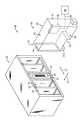
図1は、媒体ライブラリ装置10を模式的に示す。媒体(メディア)ライブラリ装置10は、少なくとも1つの媒体マガジン20と少なくとも1つの媒体処理装置40とを含むことができる。マガジン20は、個々のスロット24、26、28などの複数のスロット22を含むことができる。スロット22は、図1においてスロット28内に収容されている様子が示されている媒体記憶装置30などの媒体記憶装置を収容するように適合させることができる。媒体記憶装置30は、任意のタイプの媒体記憶装置でよい。媒体記憶装置30は、例えば、従来のディジタル線形テープ・カートリッジである。媒体記憶装置30には、媒体記憶装置30を一意に識別するためにバーコード・ラベル32が貼り付けられていることがある。
【0026】
媒体処理装置40は、一般に、上側壁42、その反対側の下側壁44、左側壁46およびその反対側の右側壁48、ならびに後側壁50およびその反対の前側壁52を有する平行六面体構造の形でよい。前側壁52は、ほぼ長方形の開口部54を含むことができる。例えばバーコード・リーダの撮像装置60は、図示したような媒体ハンドラ側壁46の内側面80(例えば、図2)に取り付けられても良い。撮像装置60は、データ接続68を介してコンピュータ・プロセッサ66に取り付けられることがある。
【0027】
操作時には、媒体処理装置40は、媒体マガジン20に対して横方向62に移動可能である。この方式で、媒体処理装置40を、媒体マガジン20のスロット22のうちの任意のスロットの隣りへと選択的に位置決めすることができる。媒体処理装置40内にあるプランジャ機構(図示せず)は、突入方向64に移動可能であり、媒体記憶装置30などの媒体記憶装置と選択的に係合するように適合されている。この方式で、媒体処理装置40は、媒体記憶装置を、媒体ライブラリ装置10内に配置された媒体マガジン20と、1つまたは複数の媒体再生/記録装置(図示せず)との間で移動させることができる。撮像装置60は、特定の媒体記憶装置を判断して識別するために、媒体記憶装置30上のバーコード・ラベル32のような媒体記憶装置上のバーコード・ラベルを読み取る役目を行うことができる。
【0028】
媒体ライブラリ装置10は、従来の媒体ライブラリ装置でよく、例えば、「撮像装置および方法の較正システム(CALIBRATION SYSTEM FOR AN IMAGING APPARATUS AND METHOD)」に関するGardnerによる第6,194,697号と、「バーコードの解読方法(METHOD OF DECIPHERING BAR CODES)」に関するKatoらによる第6,164,543号の米国特許と、1999年4月13日に出願された「レンズを光学軸からオフセットさせた光学アセンブリ(OPTICAL ASSEMBLY HAVING LENS OFFSET FROM OPTICAL AXIS)」に関するGardnerらによる出願番号09/290,842号と、1999年4月13日に出願された「自動媒体交換器用のガイド・システムおよび方法(GUIDANCE SYSTEM AND METHOD FOR AN AUTOMATED MEDIA EXCHANGER)」に関するGardnerらによる出願番号09/291,242号と、1999年4月13日に出願された「撮像装置アライメント・システムおよび方法(IMAGING APPARATUS ALIGNMENT SYSTEM AND METHOD)」に関するGardnerらによる出願番号09/290,429号と、1999年4月13日に出願された「自動光学検出システムおよび方法(AUTOMATED OPTICAL DETECTION SYSTEM AND METHOD)」に関するGardnerらによる出願番号09/290,926号と、1999年4月13日に出願された「撮像システムのためのアライメント装置および方法(ALIGNMENT APPARATUS AND METHOD FOR AN IMAGING SYSTEM)」に関するGardnerによる出願番号09/290,216の米国特許出願とのうちのいずれかに開示されたタイプのものでよい。
【0029】
図2は、媒体処理装置の側壁46の内側面80を示して、撮像装置60の詳細を示す。図2を参照すると、図示したように、側壁46は、光源取付け領域56を含むことができる。光源取付け領域56は、撮像装置60がバーコードを読み取りやすいように照明を当てるために使用されるLED光源などの従来の光源を取り付ける役割を有する。
【0030】
図2をさらに参照すると、撮像装置60は、また、ハウジング100を含むことができる。ハウジング100は、一般に、光センサ取付け領域150と、この図ではレンズ・アセンブリ210が取り付けられている状態のレンズ取付け領域200を含むことができる。図2から分かるように、レンズ・アセンブリ210は、レンズ・クリップ240によって固定することができる。
【0031】
光センサ取付け領域150は、光センサ・パッケージ152(図12)を側壁46に対して保持しかつ位置合わせするために設けることができる。この方式では、光センサ取付け領域150は、光センサ・パッケージ152をレンズ・アセンブリ210と位置合わせするはたらきをする。光センサ・パッケージ152は、例えば、日本の日本電気株式会社から型番uPD3734Aとして販売されているタイプのものでよい。光センサ取付け領域150は、光センサ・パッケージを、光センサ取付け領域150と位置合わせし、その結果側壁46、光源取付け領域56、およびレンズ取付け領域200とも位置合わせするために、基準面156、158、160、162などの様々な基準面を有し得る。光センサ取付け領域150は、例えば、前に参照した米国特許第6,118,598号に記載された光センサ取付け領域と、以下の点を除いて実質的に同一で良い。本実施の形態の光センサ取付け領域150は媒体処理装置の側壁46内に一体的に形成されているが、米国特許6,118,598に記載された光センサ取付け領域は、別のハウジング内に形成されている点で本実施の形態と異なる。
【0032】
図3は、分かりやすくするためにレンズ・アセンブリ210とレンズ保持クリップ部材240とを除去した図2のレンズ取付け領域200の詳細な破断斜視図を示す。図4は、図3と似ているが、レンズ取付け領域が、平面図で示されている。図3および図4を参照すると、レンズ取付け領域200は、媒体処理装置40の側壁46内に一体的に形成された、大まかには平行六面体の形状の凹部でよい。レンズ取付け領域200は、第1の下側面300と第2の下側面330とを含むことができる。
【0033】
第1の下側面300は、側壁46の内側面80と実質的に平行でよい。図示したように、第1の下側面300と側壁46の内側面80との間に、全体に、第1の前側壁302、第1の側壁304および第1の後側壁306(図4)が延在することができる。例えば内側面80と第1の側壁304の間に延在する丸み部分308のように、図示したような内側面80と、第1の前側壁302、第1の側壁304および第1の後壁306との間が丸み部分でつながれていてもよい。そのような丸み部分は、媒体処理装置40内の部品を移動させるための余裕を設けるためにあってもよい。図示したように、第1の下側面300から1対の支持部材310、312が延在することができる。支持部材310、312は、例えば、第1の下側面300の上に約1mmの距離だけ延在し、距離「f」だけ離される(図4)。距離「f」は、例えば、約14.5mmである。図示したように、第1の下側面300には穴314が設けられている。第1の側壁304から横方向に回転防止リブ316が延在すると良い。レンズ・アセンブリ210のための隙間(クリアランス)を設けるために、例えば図3と図6に示したように、レンズ取付け領域200にアーチ形チャネル230を設けることができる。
【0034】
第2の下側面330は、前述の第1の下側面300と類似の方法で形成することができる。具体的には、第2の下側面330は、側壁46の内側面80と実質的に平行でよい。図示したように、第2の前側壁332、第2の側壁334(図4)および第2の後壁336は、全体に、第2の下側面330と側壁46の内側面80の間に延在することができる。図示したように、1対の支持部材340、342が、第2の下側面330から上方に延在することができる。支持部材340、342は、例えば、第2の下側面330よりも上に約1mmの距離だけ延在し、前述の距離「f」だけ離される(図4)。図示したように第2の下側面300に穴334を設けることができる。第2の前側壁332から横方向に回転防止リブ346が延在しても良い。
【0035】
図3を再び参照すると、第1の棚状部分320は、第1の下側面300と実質的に平行でよい。図示したように、側壁部分322が、第1の下側面300と棚状部分320の間に延在することができる。棚状部分320は、例えば、第1の下側面300よりも約2.1mm下の距離に配置される。図示したように、第1のレンズ基準面324と第2のレンズ基準面326とは、棚状部分320から鋭角に下方に延在することができる。第1のレンズ基準面324は、第2のレンズ基準面326と実質的に同一平面上でよい。第1のレンズ基準面324と第2のレンズ基準面326との間に、それらよりもくぼんだ状態で、第1の凹状面328を配置することができる。第1の凹状面328は、第1および第2のレンズ基準面324、326と実質的に平行であるが例えばそこから約0.51mmの距離だけ離されるとよい。
【0036】
第2の棚状部分350(図4)は、前述の第1の棚状部分320と実質的に同一の方式で形成することができる。具体的には、第2の棚状部分350は、第2の下側面330と実質的に平行でよい。図示したように、第2の下側面330と第2の棚状部分350との間に側壁部分352が延在することができる。第2の棚状部分350は、例えば、第2の下側面330よりも約2.1mm下の距離に配置することができる。第3および第4のレンズ基準面354および356はそれぞれ、例えば、前述の第1と第2の基準面324、326と実質的に同一の方式で形成することができる。具体的には、第3のレンズ基準面354と第4のレンズ基準面356は、棚状部分350から鋭角に下方に延在することができる。第3のレンズ基準面354は、第4のレンズ基準面356と実質的に同一平面上でよい。第3のレンズ基準面354と第4のレンズ基準面356の間に、それよりもくぼんだ状態で、第2の凹状面358が、配置されることがある。第2の凹状面358は、第3のレンズ基準面354と第4のレンズ基準面356と実質的に平行であり、かつそこから例えば約0.51mmの距離だけ離されるとよい。
【0037】
図4を参照すると、第1のレンズ基準面324および第3のレンズ基準面354はそれぞれ、例えば約7mmの長さ「a」を有する。第2のレンズ基準面326および第4のレンズ基準面356はそれぞれ、例えば約6.8mmの長さ「b」を有する。第1の凹状面328および第2の凹状面358はそれぞれ、例えば約10mmの長さ「c」を有する。
【0038】
図3および図4をさらに参照すると、図示したように、レンズ取付け領域200は、さらにテーパ壁部分202を含むことができる。テーパ壁部分202は、例えば図2に示したようにレンズ・アセンブリをレンズ取付け領域200内に取り付けたときに、撮像光ビームがターゲット(例えば、バーコード・ラベル)からレンズ・アセンブリ210まで伝播するのを容易にするために設けられることがある。また、レンズ取付け領域200は、チャネル(溝)204を含むことがある。図2から分かるように、レンズ・アセンブリ210と、光センサ取付け領域150に取り付けられた光センサ・パッケージ152(図12)との間に妨害の無い光経路を実現するために、レンズ取付け領域200と光センサ取付け領域150との間にチャネル204が延在すると良い。
【0039】
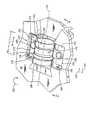
図5は、図2のレンズ取付け領域200の詳細な破断斜視図である。図5を参照すると、レンズ・アセンブリ210は、一般に、外側面216を有するハウジング212を含むことがある。例えばレンズ部材(図示せず)などの1つまたは複数の光学部品を、従来の方式で、ハウジング212内に配置することができる。図示したように、ハウジング212の外側面216に凹部214が形成されると良い。レンズ・アセンブリ210は、図示したように光学軸218を有することができる。レンズ・アセンブリ・ハウジング212は、例えば約18mmの長さ「d」を有する。凹部214は、例えば約7mmの長さ「e」を有する。レンズ・アセンブリ210は、例えば、Pentax Technologies社から部品番号81312として販売されているタイプのものである。
【0040】
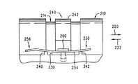
図6は、図4の線6−6に沿って切断され、レンズ取付け領域200内に支持されたレンズ・アセンブリ210を示す断面図である。図6から分かるように、レンズ・アセンブリ・ハウジング212の外側面216は、レンズ基準面324、326、354、356とだけ接触している(図4には、面324、354だけを示した)。レンズ・アセンブリの外側面216は、凹状面328、358と接触していない。図6をさらに参照すると、面324、354(面326、356と同様に)は、約90度の角度「g」をなす。
【0041】
図5を再び参照すると、図示したように、レンズ保持クリップ部材240を設けることができる。本明細書でさらに詳細に説明するように、レンズ保持クリップ部材240は、ハウジング100のレンズ取付け領域200内にレンズ・アセンブリ210を保持するはたらきをする。また、レンズ保持クリップ部材240は、レンズ・アセンブリ210を方向220、222において平行移動させることによって、撮像装置60の焦点を調整することを可能にする。焦点を調整した後で、レンズ・アセンブリ210をそれ以上平行移動させることができないようにレンズ保持クリップ部材240が適所にロックされ、撮像装置60の焦点が設定される。
【0042】
図5を参照すると、レンズ保持クリップ部材240は、図示したように、アーチ型部分242と1対の翼部分250、270を含むことができる。アーチ型部分242と翼部分250および270とはすべて、例えば約0.015インチ(0.38mm)の厚さを有するステンレス鋼から一体的に形成される。
【0043】
図7および図8を参照すると、翼部分250は、上側面252とその反対側の下側面254とを有することができる。翼部分250の前方の縁から回転防止タブ256が延在する。図7で最もよく分かるように、回転防止タブ256は、翼部分250の他の部分に対して下方に曲がっていると良い。穴258が、翼部分250を完全に貫通している。図8で最もよく分かるように、翼部分250は、アーチ型部分242の隣りに拡張部分264を有することがある。
【0044】
翼部分270は、翼部分270が拡張部分を省略することができることを除き、前述の翼部分250と実質的に同一のやり方で形成することができる。具体的には、翼部分270は、上側面272(図5)とその反対側の下側面274(図8)を有することができる。翼部分270の前方の縁から回転防止タブ276が延在することがある。前述の回転防止タブ256と同じように、回転防止タブ276は、翼部分270の残りの部分に対して下方に曲がっていると良い。穴278が、翼部分250の穴258と同じように翼部分270を完全に貫通する。
【0045】
図4を参照すると、前述のように翼部分250の拡張部分264を含むために翼部分270より長い翼部分250(図8)に適応させるために、レンズ取付け領域の第2の下側面330の幅「h」は、第1の下側面300の幅「i」よりも長いことがあることに注意されたい。
【0046】
レンズ保持クリップ部材240は、レンズ・アセンブリを平行移動させることによって撮像装置の焦点を調整した後で、レンズ・アセンブリ210をハウジング200のレンズ取付け領域210内に固定するはたらきをする。この合焦操作について、次に詳しく説明する。
【0047】
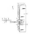
図13は、撮像装置60の焦点を設定するために使用することができる焦点設定装置400を概略的に示す。焦点設定装置400は、一般に、取付け具410と可動アーム420とを含むことができる。図示したように、取付け具410は、媒体処理装置40(図1)の側壁46を確実に保持するように構成されている。可動アーム420は矢印220、222で示した向きに移動するように適合され、図示したようにレンズ・アセンブリ210と係合するように適合された交差部分422を含むことができる。
【0048】
撮像装置60の焦点を設定するために、図13に示したように、側壁46を焦点設定装置400の取付け具(fixture)410に嵌め込むことができる。レンズ・アセンブリ210が、レンズ基準面324、326、354、356(図3と図4)上において支持されるように、レンズ・アセンブリ210をレンズ取付け領域200に入れることができる。次に、レンズ保持クリップ部材240を、レンズ・アセンブリ210上を覆うように配置することができる。図9に、この状態を示す。図9から分かるように、レンズ保持クリップ部材の翼部分250の下側面254は、支持部材340、342上に乗っている。図9に示していないが、同じように、レンズ保持クリップ部材の翼部分270の下側面が、支持部材310、312(図3)上に乗っており、レンズ保持クリップ部材の翼250、270の穴(例えば、穴256(図7))が、ハウジング200(図3)の穴334、300と位置合わせされている。
【0049】
次に、1対のねじ260、280(図5)をそれぞれ、レンズ保持クリップ部材の翼部分250、270の穴に差し込み、それぞれハウジング200(図3)内の穴334、304にねじ的に係合させることができる。図10は、第1の所定のレベルのトルクをねじ260、280に加えている状況を示す。この第1のレベルのトルクは、例えば、約1インチ・ポンドである。ねじ260に加えられるトルクによって、翼部分250が、支持部材340と342の間で下方にたわみ、その結果翼部分250の外側部分(回転防止タブ256を含む)が上方にたわんでいることが分かる。図10に示していないが、また、ねじ280に加えられるトルクによって、翼部分270が、支持部材310と312の間で下方にたわみ、その結果、翼部分270の外側部分(回転防止タブ276を含む)が上方にたわむ。
【0050】
レンズ保持クリップ部材240は、図10に示した状態で、レンズ保持クリップ部材のアーチ型部分242が、レンズ・アセンブリ210と接触しないようにサイズが決められる。したがって、レンズ・アセンブリ210を方向220、222に平行移動させて、レンズ・アセンブリの焦点を合わせることができる。レンズ保持クリップ部材の翼部分250、270をそれぞれ、支持部材340、342と310、312の間で下方にたわませることは、合焦操作中にレンズ保持クリップ部材240がしっかりと適所に固定されるので、有利である。というのは、例えば、合焦操作中にレンズ・アセンブリ210を平行移動させているときに、レンズ保持クリップ部材240が揺動したり、場合によってはレンズ・アセンブリ210に食い込んだりするのを防ぐことができるからである。支持部材310、312、340、342(例えば、図3)は、前述のようにレンズ・クリップ部材の翼部分250、270をわずかにたわみやすくすることが分かる。
【0051】
その後で、可動アーム420の交差部分422(図13)を移動させて、レンズ・アセンブリ210と接触させることができる。そのように接触した後で、レンズ・アセンブリ210に対して可動アーム420を方向220、222に使用して、撮像装置60の焦点を調整できることが分かる。この平行移動中に、可動アーム420は、方向224に沿うわずかな下方の力をレンズ・アセンブリ210に加えることができる。この下方の力により、レンズ・アセンブリ・ハウジング212(図5)とレンズ基準面324、326、354、356、(図3と図4)とが確実に接触する。その結果、この接触により、光センサ・パッケージ152(図12)に対するレンズ・アセンブリの光学軸218(図5)の位置合わせが維持される。
【0052】
図11は、レンズ・アセンブリ210の合焦後に、レンズ保持クリップ部材を使用してレンズ・アセンブリ210を適切な位置にロックすることができる状態を示す。これを達成するために、第2の所定のレベルのトルクが、ねじ260、280に加えられ、それにより、レンズ保持クリップ部材(および、特に、レンズ保持クリップ部材の翼部分250(図8)の拡張部分264)が、塑性変形し、その結果、レンズ保持クリップ部材のアーチ形部分242が、レンズ・アセンブリ210と強制的に接触し、そこに下向きの力を加えて、レンズ・アセンブリを適所にロックする。この第2のレベルのトルクは、例えば、約5インチ・ポンドである。図11から分かるように、この状態では、レンズ保持クリップ部材の翼部分250の下側面254が実際に、レンズ取付け領域200の第2の下側面330と接触していることが想定される。同じように、図11に示していないが、レンズ保持クリップ部材の翼部分270の下側面274は、実際にレンズ取付け領域200の第1の下側面300と接触し得る。
【0053】
以上、合焦操作を、単なる例示のために自動焦点設定装置400を使用して説明したことに注意されたい。この代わりに、実際には、レンズ・アセンブリ210の平行移動は、他のタイプの自動焦点設定装置または手動プロセスを使用して達成することができる。
【0054】
前に説明したように、撮像装置内で、レンズの光学軸が光センサ・パッケージと正確に位置合わせされていることが好ましい。レンズと光センサ・パッケージとの間にわずかな位置ずれがあっても、光ビームと光センサ・パッケージとの間に大きな位置ずれが生じ、それに呼応して撮像品質が低下することがある。例えば、前述のレンズ・アセンブリ210の場合、光学軸218(図5)は、撮像装置60の光センサ・パッケージ152(図12)と垂直なままであることが好ましい。前述のレンズ取付け領域200は、次に詳細に説明するように、レンズ・アセンブリ210と撮像装置の光センサ・アレイとの間の所望のアライメントを維持する機能を高める。
【0055】
レンズ・アセンブリ基準面324、326、354、356の目的は、光センサ・パッケージ152(図12)に対してレンズ・アセンブリ210の位置と向きを適切に決め、それによりレンズ・アセンブリ210と光センサ・パッケージ152との間に正確なアライメントを実現しながら、レンズ・アセンブリ210を方向220、222(図5)に移動させてレンズの焦点を合わせることである。
【0056】
理想的には、レンズ基準面は、円筒状のレンズ・ハウジングと線接触しなければならない。しかしながら、実際には、完全に平坦な基準面を製造することはきわめて困難であり、狂いがわずかではあるが、ほとんど必ず存在する。そのような狂いが、レンズ・アセンブリのアライメントに悪い影響を与えることが分かっている。特に、そのような狂いは、レンズ・アセンブリの光学軸を望ましい向きから傾かせ、したがって光センサ・アレイに対して垂直ではなくならせることがある。
【0057】
しかしながら、そのような狂いが、レンズ・アセンブリの端部近くにあるときは、(レンズ・アセンブリの中央近くにあるときと比べて)レンズ・アセンブリ・アライメントに及ぼす影響が小さいことが分かっている。前述のレンズ取付け領域200は、レンズの中央の近くに凹状面328、358を設けることによって、レンズ・アセンブリの中央の近くに狂いが存在しないようにする。前述のように、そのような凹状面328、358はレンズ・アセンブリ210と接触せず、レンズ基準面324、326、354、356(レンズ・アセンブリ210の端部近くにある)だけがレンズ・アセンブリと接触する。したがって、本明細書で説明するレンズ取付け領域200は、基準面の狂いがレンズ・アセンブリのアライメントに与える影響を小さくする。
【0058】
前述のように、レンズ・アセンブリ210と光センサ・パッケージ152との間に正確なアライメントおよび位置決めを維持することが好ましい。しかしながら、(前述のように)レンズ保持クリップ部材を取り付けるときに、クリップ部材の押さえねじにトルクを加えることで、レンズ保持クリップ部材にトルクすなわちモーメントが加わる場合があることが分かっている。このトルクすなわちモーメントにより、レンズ保持クリップ部材がわずかに回転することがある。このため、レンズ・アセンブリ210がわずかに回転したり(その結果、レンズ・アセンブリの光学軸が、光センサと垂直でなくなる)、レンズ・アセンブリが光センサの方向または光センサから離れる方向に直線的に移動したりする(その結果、系の焦点に有害な影響を与える)ことがある。
【0059】
後で詳細に説明するように、本明細書で説明した撮像装置60は、レンズ・アセンブリのそのような回転または直線運動を防ぎ、それにより撮像装置60によって生成することができる画像品質を高めるという設備を有する。例えば、図5を参照すると、時計回り方向の締付けトルク226がねじ260、280に加えられるとき、このトルクのある成分が、(ねじ260、280の頭と上側面252、272との間の摩擦接触により)レンズ保持クリップ部材240に伝達されやすいことが分かる。この伝達されたトルクは、レンズ保持クリップ部材240を時計回り方向226に回転させる。しかしながら、レンズ保持クリップ部材の回転防止タブ256、276が、ハウジング回転防止リブ346、316とそれぞれ連携して伝達トルクに抵抗し、レンズ保持クリップ部材240が回転するのを防ぐ。具体的には、図5から分かるように、レンズ保持クリップ部材の回転防止タブ256は、ハウジング200に対するレンズ保持クリップ部材240の時計回りの回転に抵抗するようにハウジング回転防止リブ346と接触する。類似の態様で、レンズ保持クリップ部材の回転防止タブ276は、やはりハウジング200に対するレンズ保持クリップ部材240の時計回りの回転に抵抗するようにハウジング回転防止リブ316と接触する。
【0060】
以上のことから分かるように、レンズ保持クリップ部材の回転防止タブ256、276は、ハウジング回転防止リブ316、346と連携して、ねじ260、280が締付けられている間のレンズ保持クリップ部材240の回転を防く。それにより、光センサ・パッケージ152に対するレンズ・アセンブリ210の最終的なアライメントの精度が向上する。
【0061】
例えば、図7を参照すると、レンズ保持クリップ部材の回転防止タブ256、276(図7では256だけを示した)が、レンズ保持クリップ部材の翼部分(250、270)の他の部分に対して下方に傾斜している(図7に示したように)ことが分かる。この下向きの傾斜により、ねじ260、280(例えば、図5)が締め付けられ、レンズ保持クリップ部材の翼250、270に歪みが生じたときでも、回転防止タブ256、276が、ハウジング回転防止リブ316、346と(既述の場合と同様の態様で)接触し続けることが保証される。
【0062】
例えば、図10および図11を参照すると、支持部材340、342の間の翼部分250の下方へのたわみによって、翼部分250の前部分および後部分(図10および図11に示した)が上方にたわむことが分かる。しかしながら、回転防止タブ256が翼部分250の他の部分に対して下方に傾斜しているため、図10および図11に示したように翼部分250がたわんだときでも、回転防止タブが、ハウジング回転防止リブ346(例えば図5)と接触し続けることが保証される。したがって、回転防止タブ256、276の下方の傾斜は、前述の回転防止機能が、すべての条件において機能することを保証する。
【0063】
前述の取付け手順の代わりとして、中間の締付けステップ(図10に示したような)を省略することができる。この場合には、ねじ260、280を差し込む前に、レンズ・アセンブリ210の焦点を設定することになる。次に、所望の焦点が達成されたとき、図11に示したようにねじを差し込んで完全に締め付けることができる。この代替策は、焦点設定手順から1つのステップをなくすことができるため、状況によって有利なことがある。具体的には、図10に示した中間のステップをなくすことができる。この代替手順を使用すると、支持部材310、312、340、342(例えば、図3)を省略することができる。その理由は、そのような支持部材の目的が、前述のように、図10に示した中間ステップの間にレンズ保持クリップ部材の翼部分250、270が少しわむみことを許容することであるからである。支持部材310、312、340、342を省略した場合は、前に説明し図7に示したように、レンズ保持クリップ部材の回転防止タブ256、276を、回転防止タブ256に対して下方に傾斜させる必要もなくなる。
【0064】
前述の代替策は、状況によっては有利なことがあるが、いくつかのケースでは、焦点を設定している間にレンズ保持クリップ部材が安定しかつ所望の場所にあることを保証するために、中間の締付けステップを無くさずに維持した方がよいことがある。
【0065】
図12に示したように、側壁46の内側面80にシュラウド(囲い板)部材70を取り付けることができる。シュラウド部材70は、迷光が光センサ・パッケージ152に到達するのを防ぐために設けられることがある。また、シュラウド部材70は、光センサ・パッケージ152上に下方の力を与えて、光センサ・パッケージが光センサ取付け領域150の基準面と密着したままになるようにすることができる。シュラウド部材70は、例えば、ナイロン610などの塑性材料から製造される。側壁46は、例えば、ポリカーボネートなどの塑性材料からなる。側壁46およびシュラウド部材70は両方とも、例えば、従来の射出成形プロセスで形成される。
【0066】
光センサ取付け領域150およびレンズ取付け領域200の両方を側壁46に一体的に形成することによって、光センサ取付け領域150をレンズ取付け領域200を基準として正確に対応させることができ、また、光センサ取付け領域150およびレンズ取付け領域を側壁46を基準として正確に対応させることができることが分かる。したがって、前述のように取り付けられた光センサ・パッケージ152は、レンズ・アセンブリ210を基準として正確に対応する。さらに、光センサ・パッケージ152およびレンズ・アセンブリ210の両方が側壁46を基準として正確に合わされる。
【0067】
以上の事柄は、単なる例示のために、媒体処理装置内のバーコード・リーダと関連して説明したことに注意されたい。代替として、本明細書で説明した装置および方法は、組み立てライン上の固定バーコード・リーダや携帯型バーコード・スキャナなどの任意の用途のバーコード・リーダに使用することができる。また、この装置および方法は、バーコード・リーダ以外の撮像システムにも使用することができる。その例には、光学式走査装置、写真複写機およびテレファックス装置がある。
【0068】
この説明全体にわたって使用される様々な数値寸法および明細は、単なる例示のために提供され、併記の特許請求の範囲に列挙された発明をいかなる形でも制限しないように解釈されるべきであることに注意されたい。
【0069】
本明細書において、本発明の例示的で現在好ましい実施形態を説明したが、本発明の概念を、他の状況において様々な形で実施し利用することができ、特許請求の範囲が、従来技術によって制限された範囲を除きそのような変形を含むように解釈されるべきであることを理解されたい。本発明には、以下のような実施の態様がある。
【0070】
(実施の態様1) 撮像装置(60)であって、
少なくとも1つの第1の基準面(324、354)と少なくとも1つの第2の基準面(326、356)とを有する撮像装置ハウジング(100)を備え、
前記少なくとも1つの第1の基準面(324、354)が、前記少なくとも1つの第2の基準面(326、356)と同一平面上にあり、
前記少なくとも1つの第1の基準面10(324、354)が、前記少なくとも1つの第2の基準面(326、356)と不連続であり、
前記少なくとも1つの第1の基準面(324、354)および前記少なくとも1つの第2の基準面(326、356)の両方と接触する少なくとも1つのレンズ・アセンブリ(210)と
を備える撮像装置。
【0071】
(実施の態様2) 前記少なくとも1つの第1の基準面(324、354)と前記少なくとも1つの第2の基準面(326、356)との間に形成された凹部(328、358)をさらに有する実施の態様1に記載の撮像装置。
【0072】
(実施の態様3) 前記撮像装置ハウジング(100)が、少なくとも1つの第3の基準面(324、354)と少なくとも1つの第4の基準面(326、356)とをさらに有し、
前記少なくとも1つの第3の基準面(324、354)が、前記少なくとも1つの第4の基準面(326、356)と同一平面上にあり、
前記少なくとも1つの第3の基準面(324、354)が、前記少なくとも1つの第4の基準面(326、356)と不連続であり、
前記少なくとも1つのレンズ・アセンブリ(210)が、前記少なくとも1つの第3の基準面(324、354)および前記少なくとも1つの第4の基準面(326、356)の両方と接触している実施の態様1に記載の撮像装置。
【0073】
(実施の態様4) 前記少なくとも1つの第3の基準面(324、354)と前記少なくとも1つの第4の基準面(326、356)との間に形成された凹部(328、358)をさらに有する実施の態様3に記載の撮像装置。
【0074】
(実施の態様5) 撮像装置(60)を組み立てる方法であって、
少なくとも1つの第1の基準面(324、354)と少なくとも1つの第2の基準面(326、356)とを有する撮像装置ハウジング(100)を準備する段階と、
少なくとも1つのレンズ(210)を準備する段階と、
前記少なくとも1つの第1の基準面(324、354)が、前記少なくとも1つの第2の基準面(326、356)と同一平面上にあり、
前記少なくとも1つの第1の基準面(324、354)が、前記少なくとも1つの第2の基準面(326、356)と不連続であり、
前記少なくとも1つの第1の基準面(324、354)と前記少なくとも1つの第2の基準面(326、356)とを使用して、前記レンズ(210)を前記前記撮像装置ハウジング(100)と位置合わせする段階を含む撮像装置の組立方法。
【0075】
(実施の態様6) 前記少なくとも1つの第1の基準面(324、354)と前記少なくとも1つの第2の基準面(326、356)との間に形成された凹部(328、358)を準備する段階をさらに含む実施の態様5に記載の方法。
【0076】
(実施の態様7) 前記撮像装置ハウジング(100)に、少なくとも1つの第3の基準面(324、354)と少なくとも1つの第4の基準面(326、356)とを設ける段階と、
前記少なくとも1つの第3の基準面(324、354)が、前記少なくとも1つの第4の基準面(326、356)と同一平面上にあり、
前記少なくとも1つの第3の基準面(324、354)が、前記少なくとも1つの第4の基準面(326、356)と不連続であり、
前記少なくとも1つの第3の基準面(324、354)および前記少なくとも1つの第4の基準面(326、356)を使用して、前記レンズ(210)を前記撮像装置ハウジング(100)と位置合わせする段階と
をさらに有する実施の態様5に記載の方法。
【0077】
(実施の態様8) 前記少なくとも1つの第3の基準面(324、354)と前記少なくとも1つの第4の基準面(326、356)との間に凹部(328、358)を設ける段階をさらに含む実施の態様7に記載の方法。
【0078】
(実施の態様9) 撮像装置であって、
部材(46)と、
前記部材(46)に形成された少なくとも1つの第1の基準面(158、160、162、164)と、
前記部材(46)に形成された少なくとも1つの第2の基準面(324、326、354、356)と、
前記部材(46)に形成され、少なくとも1つの光源を取り付けるように適合された少なくとも1つの取付け機構(56)と、
少なくとも1つの光センサ・パッケージ(152)と、
少なくとも1つの光学部品(210)と
を含み、
前記少なくとも1つの光センサ・パッケージ(152)が、前記少なくとも1つの第1の基準面(158、160、162、164)と接触しており、前記少なくとも1つの光学部品(210)が、前記少なくとも1つの第2の基準面(324、326、354、356)と接触しており、
前記第1の基準面(158、160、162、164)、前記第2の基準面(324、326、354、356)、および前記取付け機構(56)がすべて、前記部材(46)に一体的に形成されている撮像装置。
【0079】
(実施の態様10) 撮像システム(60)であって、
少なくとも1つの基準面(324、326、354、356)が付属する撮像システム・ハウジング(100))と、
前記少なくとも1つの基準面(324、326、354、356)と接触している少なくとも1つのレンズ・アセンブリ(210)と、
前記レンズ・アセンブリ(210)に接触している少なくとも1つの部材(240)と、
前記少なくとも1つの部材(240)を前記撮像システム・ハウジング(100)に取り付ける少なくとも1つのコネクタ(260、280)と
を含み、
前記撮像システム(60)が、少なくとも第1の操作状態および第2の操作状態を含み、
前記第1の操作状態においては、
前記少なくとも1つのレンズ・アセンブリ(210)が、前記ハウジング(100)に対して平行移動が可能であり、
前記少なくとも1つのコネクタ(260、280)が、前記少なくとも1つの部材(240)に第1のレベルの力を加えており、
前記第2の操作状態においては、
前記少なくとも1つのコネクタ(260、280)が、前記少なくとも1つの部材(240)に第2のレベルの力を加えており、該第2のレベルの力は該第1のレベルの力よりも大きく、
前記少なくとも1つの部材が、前記第1の操作状態に比べて塑性変形され、
前記少なくとも1つの部材(240)が、前記少なくとも1つのレンズ・アセンブリ(210)と強制的に接触した状態であり、
前記少なくとも1つのレンズ・アセンブリ(210)が、前記ハウジング(100)に対して平行移動が可能ではない撮像システム。
【図面の簡単な説明】
【図1】 媒体処理装置および媒体マガジンを含む媒体ライブラリ装置の斜視図である。
【図2】 光センサ取付け領域およびレンズ取付け領域を示す図1の媒体処理装置の壁部分の斜視図である。
【図3】 分かりやすくするために、レンズ・アセンブリとレンズ保持クリップ部材を除去した図2のレンズ取付け領域の詳細な破断斜視図である。
【図4】 図3に詳細に示したレンズ取付け領域の平面図である。
【図5】 図2のレンズ取付け領域の詳細な破断斜視図である。
【図6】 例示のためにレンズ・アセンブリが追加された、図4の線6−6線に沿う切断面の構造の断面図である。
【図7】 図2のレンズ取付け領域と関連して使用可能なレンズ保持クリップ部材の側面立面図である。
【図8】 図7のレンズ保持クリップ部材の下面図である。
【図9】 図5の線9−9に沿う切断面の構造の、保持ねじを差し込む前の状態を示す部分断面破断図である。
【図10】 図9と類似の図であり、保持ねじを第1の高さに差し込み締め付けた後の状態を示す部分断面破断図である。
【図11】 図9および図10と類似の図であり、保持ねじを第2の高さまで差し込み締め付けた後の状態を示す部分断面破断図である。
【図12】 図2の壁部分に取り付けられた光センサ・パッケージおよびシュラウドを示す斜視図である。
【図13】 焦点設定装置の斜視図である。
【符号の説明】
46 部材
56 取付け機構
60 撮像装置
100 撮像装置ハウジング
152 光センサ・パッケージ
158、160、162、164 基準面
210 レンズ・アセンブリ
324、326、354、356 第1の基準面
328、358 凹部
240 部材[0001]
BACKGROUND OF THE INVENTION
The present invention relates generally to imaging systems and, more particularly, to imaging systems of the type that include an optical sensor and at least one lens.
[0002]
[Prior art]
An imaging device is used to generate machine readable data representing an image of an object, such as a page of printed text. One type of imaging device is a photoelectric imaging device. As used herein, the term “photoelectric imaging device” means any device that generates data representing an object to be imaged by using an optical sensor array such as a charge coupled device (CCD). . Examples of photoelectric imaging devices include devices such as video devices with cameras and digital cameras that instantaneously focus the entire image captured on the two-dimensional photosensor array. Another example of a photoelectric imaging device is a line-focus system.
[0003]
Some linear focus systems image a target by sweeping a scan head over the target and sequentially focusing a narrow “scan line” portion of the target on the linear photosensor array. Examples of such devices, commonly referred to as optical scanners, include computer input devices commonly referred to simply as “scanners” as well as facsimile machines and digital copiers.
[0004]
Linear focus systems are also used in some bar code readers. In general, in a linear focus barcode reader, a narrow portion of the barcode is imaged onto a linear photosensor array. The imaging bar code can then be read by analyzing the electrical output from the photosensor array. An example of an imaging device that can be used in combination with a bar code reader is US Pat. No. 6, Gardner, Jr. for “Method and apparatus for setting focus on imaging device”. No. 118,598, and US Patent Application No. 09/290 by Gardner, Jr. filed Apr. 13, 1999, for "ALIGNMENT APPARATUS AND METHOD FOR AN IMAGEING SYSTEM". 216, both of which are incorporated herein by reference for all that is disclosed.
[0005]
In a linear focus system, a light beam from an illuminated line object is imaged by a lens onto a linear photosensor array located far from the line object. A linear photosensor array is a one-dimensional array of optical elements that correspond to small area positions on a line object. Such small areas on a line object are commonly referred to as “picture elements” or “pixels”. Depending on the light from its corresponding pixel location on the line object, each photosensor pixel element in the linear photosensor array (sometimes referred to simply as a “pixel”) is the time immediately preceding the sampling interval. A data signal representing the light intensity received during the interval is generated. All optical element data signals are received and processed by a suitable data processing system.
[0006]
In a color optical scanner, a plurality of spectrally separated imaging beams (typically red, green and blue beams) must be projected onto the photosensor array. The structure and operation of a color optical scanner is described in US Pat. No. 4,870,268 by Vincent et al., “OPTICAL SCANNER” for “COLOR COMBINERS AND SEPARATOR AND IMPLEMENTATIONS”. No. 4,926,041 by Boyd (and corresponding EPO Patent No. 0410578), “OPTICAL SCANNER WITH MIRROR MOUNTED OCCLUDING APERTURE ORFILTER”. US Pat. No. 5,019,703 to Boyd et al. (And corresponding EPO patent 04388). 68), US Pat. No. 5,032,004 by Boyd et al. (And corresponding EPO Patent No. 0458492 for “BEAM SPLITTER APPARATUS WITH ADJUSTABLE IMAGE FOCUS AND REGISTRATION”). ), US Pat. No. 5,044,727 (and corresponding EPO patent 0455450) by Steinle for “BEAM SPLITTER / COMBINER APPARATUS”, “with path length compensator Stei on beam splitter / combiner (BEAM SPLITTER / COMBINER WITH PATH LENGTH COMPENSATOR) U.S. Pat. No. 5,040,872 to Le, U.S. Pat. No. 5,227,620 to Elder, Jr et al. (and APPARATUS FOR ASSEMBLING COMPONENT OF COLOR OPTICAL SCANNERS). US Pat. No. 5,410,347 to Steinle et al., Corresponding to “Color Optical Scanner with Image Positioning and Retaining Assembly” (Corresponding EPO Patent No. 0576788). All of these patents are specifically incorporated herein by reference for all disclosed matters. Murrell.
[0007]
In an imaging apparatus, particularly a linear focus type imaging apparatus as described above, it is preferable to accurately align a light beam from an object with an optical sensor array in order to accurately capture an image. In a typical linear focus scanning device, the imaging light beam is sent by one or more optical components (eg, lenses) before reaching the photosensor array. Even small deviations between such optical components and the optical sensor array result in a large misalignment between the light beam and the optical sensor array, which results in a corresponding reduction in image quality. There are things to do.
[0008]
US Pat. No. 5,646,394 by Steinle et al. For “IMAGING DEVICE WITH BEAM STEARING CAPABILITY” and “Photoelectric Imaging Method and US Pat. No. 6,147,343 by Christensen for “PHOTOELECTRIC IMAGEING METHOD AND APPARATUS”, both of which are specifically incorporated herein by reference for all disclosed matters. It is.
[0009]
In general, the optical components of the imaging device are mounted within the imaging device housing. The photosensor array is typically attached to a circuit board that is attached to the imager housing. In general, a lens is mounted in the imaging device housing. This lens serves to focus the image of the object on the photosensor array. In order for the imaging device to function properly, the focal point of the lens must be set accurately.
[0010]
After the imaging device is assembled, the focus of the lens is generally adjusted. Typically, this is done by adjusting the distance between the lens and the photosensor array, i.e. the image distance of the optical system, until the focus is appropriate. In order to achieve this, it is customary to provide an imaging device having one or more reference planes for positioning the lenses. Such a reference plane generally allows the lens to translate only in one mobility, i.e. towards or away from the optical sensor, and prevents the lens from shifting in the other direction. If such a shift is allowed, the shift causes the lens position to shift with respect to the photosensor array. Thus, the reference surface allows the focus of the lens to be adjusted while maintaining alignment between the lens and the photosensor array. The reference surface of the lens schematically described above takes the form of, for example, a cylindrical surface or a V-shaped groove.
[0011]
In addition, the imaging apparatus typically includes a bracket and other holding mechanism that locks the lens in place with respect to the reference plane after setting the focus of the imaging system. The bracket is fixed by screws, for example. Thus, the screw is loosened when it is desired to move the lens to focus the system and tightened to lock the lens in place when the proper focus is achieved.
[0012]
[Problems to be solved by the invention]
Conventional holding mechanisms have been found to be problematic in that they often cause lens misalignment during focusing operations. For example, in the case of the above-described screw holding bracket, if the screw is loosened too much before the focusing operation, the lens can be rotated away from the reference surface, which may cause a deviation. In addition, the screw may not be tightened sufficiently to lock the lens after the focusing operation is completed. As a result, even after the lens is locked, the lens may deviate from the in-focus position. Furthermore, it has been found that the torque applied to tighten the holding screw is transmitted to the lens, which may cause the lens to rotate and shift the alignment.
[0013]
Further, it has been found that the conventional holding mechanism is not suitable for adjustment by an automatic focus adjustment device which is generally used for setting a focus in an imaging apparatus.
[0014]
Accordingly, it is desirable to provide an optical imaging device that provides accurate alignment between the photosensor array and other optical components in the device.
[0015]
[Means for Solving the Problems]
An imaging device is disclosed that generates data that can be read by a machine that represents an imaged object. The imaging device can include an imaging device housing, the imaging device housing including at least one first reference plane and at least one second reference plane. The at least one first reference plane is coplanar with the at least one second reference plane. The at least one first reference plane is discontinuous with the at least one second reference plane. The at least one lens assembly may be in contact with both at least one first reference surface and at least one second reference surface.
[0016]
Also disclosed is a method of assembling an imaging device that generates machine readable data representing an imaging object. The method can include providing an imaging device housing having at least one first reference plane and at least one second reference plane and providing at least one lens. The at least one first reference plane is coplanar with the at least one second reference plane. The at least one first reference plane is discontinuous with the at least one second reference plane. The method further includes aligning the lens with the imager housing using at least one first reference surface and at least one second reference surface.
[0017]
DETAILED DESCRIPTION OF THE INVENTION
Disclosed herein is an improved lens focusing and holding mechanism for an imaging system of the type including, for example, a photosensor array. The lens can be translated along the reference plane in contact with and away from the photosensor array to adjust the focus of the imaging system while in contact with the reference plane formed in the imaging system housing It is.
[0018]
The reference surface can be configured to contact the lens only near its end. To achieve this, a concave area can be provided near the center of the lens. By limiting contact to the outer portion of the lens, the effects that irregularities in the reference plane would otherwise have on alignment are minimized.
[0019]
A lens retaining clip may be provided to secure the lens within the imaging system housing. The lens retaining clip can remain stationary while the lens is translated during the focusing operation. After achieving the desired focus, the lens retaining clip can be secured in place, for example with a retaining screw, so that the lens retaining clip is plastically deformed to ensure that the lens is held in the desired position. The lens retaining clip can include a detent tab that cooperates with a detent rib on the housing to prevent torque applied to the retaining screw from rotating the lens retaining clip.
[0020]
The imaging system housing can include a spaced apart support member that supports the lens retaining clip when initially installed. A first torque can be applied to the holding screw of the lens holding clip to deflect a portion of the lens holding clip downward between the support members. This deflection enables the lens holding clip to be fixed during the focus adjustment operation. After setting the focus, a higher level of torque can be applied to the holding screw to lock the lens in place.
[0021]
The lens reference plane and the photosensor reference plane are formed integrally in the structure, which makes it easy to achieve alignment between the lens reference plane and the photosensor reference plane and between the reference plane and the structure itself. Can be maintained.
[0022]
1-13 illustrate an
[0023]
1 to 13 generally illustrate a method of assembling an
[0024]
While the apparatus and method have been described generally above, they will now be described in further detail.
[0025]
FIG. 1 schematically shows a
[0026]
The
[0027]
During operation, the
[0028]
The
[0029]
FIG. 2 shows details of the
[0030]
With further reference to FIG. 2, the
[0031]
[0032]
FIG. 3 shows a detailed cutaway perspective view of the
[0033]
The first
[0034]
The second
[0035]
Referring back to FIG. 3, the
[0036]
The second shelf portion 350 (FIG. 4) can be formed in substantially the same manner as the
[0037]
Referring to FIG. 4, the first
[0038]
With further reference to FIGS. 3 and 4, as illustrated, the
[0039]
FIG. 5 is a detailed cutaway perspective view of the
[0040]
FIG. 6 is a cross-sectional view of the
[0041]
Referring again to FIG. 5, a lens
[0042]
Referring to FIG. 5, the lens
[0043]
With reference to FIGS. 7 and 8, the
[0044]
The
[0045]
Referring to FIG. 4, to accommodate a wing portion 250 (FIG. 8) that is longer than the
[0046]
The lens
[0047]
FIG. 13 schematically illustrates a
[0048]
In order to set the focus of the
[0049]
Next, a pair of
[0050]
The lens
[0051]
Thereafter, the intersection 422 (FIG. 13) of the
[0052]
FIG. 11 shows a state where the
[0053]
It should be noted that the focusing operation has been described above using the automatic
[0054]
As previously described, it is preferred that the optical axis of the lens is accurately aligned with the photosensor package within the imaging device. Even if there is a slight misalignment between the lens and the optical sensor package, a large misalignment may occur between the light beam and the optical sensor package, and the imaging quality may be reduced accordingly. For example, for the
[0055]
The purpose of the lens assembly reference planes 324, 326, 354, 356 is to properly position and orient the
[0056]
Ideally, the lens reference surface should be in line contact with the cylindrical lens housing. In practice, however, it is extremely difficult to produce a perfectly flat reference surface, and there is almost always a slight deviation. Such a deviation has been found to adversely affect the alignment of the lens assembly. In particular, such deviations can cause the optical axis of the lens assembly to tilt from the desired orientation and thus become non-perpendicular to the photosensor array.
[0057]
However, it has been found that such a deviation has a small effect on lens assembly alignment when it is near the end of the lens assembly (as compared to when it is near the center of the lens assembly). The
[0058]
As described above, it is preferable to maintain accurate alignment and positioning between the
[0059]
As will be described in detail later, the
[0060]
As can be seen from the above, the
[0061]
For example, referring to FIG. 7, the
[0062]
For example, referring to FIGS. 10 and 11, the downward deflection of the
[0063]
As an alternative to the mounting procedure described above, an intermediate tightening step (as shown in FIG. 10) can be omitted. In this case, the focal point of the
[0064]
The above alternatives may be advantageous in some situations, but in some cases, to ensure that the lens retaining clip member is stable and in the desired location while setting the focus, It may be better to maintain an intermediate tightening step without losing it.
[0065]
As shown in FIG. 12, a
[0066]
By integrally forming both the optical
[0067]
It should be noted that the foregoing has been described in connection with a bar code reader in a media processing device for exemplary purposes only. Alternatively, the devices and methods described herein can be used with any application barcode reader, such as a fixed barcode reader or portable barcode scanner on an assembly line. The apparatus and method can also be used for imaging systems other than barcode readers. Examples include optical scanning devices, photocopiers and telefax machines.
[0068]
Various numerical dimensions and descriptions used throughout this description are provided for purposes of illustration only and should not be construed to limit the invention as recited in the appended claims in any way. Please be careful.
[0069]
While exemplary and presently preferred embodiments of the present invention have been described herein, the concepts of the present invention can be implemented and utilized in various ways in other situations, and the claims are hereby incorporated by reference. It should be understood that it should be construed to include such variations except to the extent limited by. The present invention has the following embodiments.
[0070]
(Embodiment 1) An imaging device (60),
An imaging device housing (100) having at least one first reference surface (324, 354) and at least one second reference surface (326, 356);
The at least one first reference surface (324, 354) is coplanar with the at least one second reference surface (326, 356);
The at least one first reference surface 10 (324, 354) is discontinuous with the at least one second reference surface (326, 356);
At least one lens assembly (210) in contact with both the at least one first reference surface (324, 354) and the at least one second reference surface (326, 356);
An imaging apparatus comprising:
[0071]
(Embodiment 2) A recess (328, 358) formed between the at least one first reference surface (324, 354) and the at least one second reference surface (326, 356) is further provided. The imaging device according to Embodiment 1 which includes the imaging device.
[0072]
(Embodiment 3) The imaging device housing (100) further includes at least one third reference surface (324, 354) and at least one fourth reference surface (326, 356),
The at least one third reference plane (324, 354) is coplanar with the at least one fourth reference plane (326, 356);
The at least one third reference plane (324, 354) is discontinuous with the at least one fourth reference plane (326, 356);
Implementation wherein the at least one lens assembly (210) is in contact with both the at least one third reference surface (324, 354) and the at least one fourth reference surface (326, 356). The imaging device according to aspect 1.
[0073]
(Embodiment 4) A recess (328, 358) formed between the at least one third reference surface (324, 354) and the at least one fourth reference surface (326, 356) is further provided. An image pickup apparatus according to Embodiment 3 having the image pickup apparatus.
[0074]
(Embodiment 5) A method for assembling an imaging device (60), comprising:
Providing an imaging device housing (100) having at least one first reference surface (324, 354) and at least one second reference surface (326, 356);
Providing at least one lens (210);
The at least one first reference surface (324, 354) is coplanar with the at least one second reference surface (326, 356);
The at least one first reference surface (324, 354) is discontinuous with the at least one second reference surface (326, 356);
Using the at least one first reference surface (324, 354) and the at least one second reference surface (326, 356), the lens (210) is connected to the imaging device housing (100). An assembling method of an imaging apparatus including an alignment step.
[0075]
(Embodiment 6) Prepare recesses (328, 358) formed between the at least one first reference surface (324, 354) and the at least one second reference surface (326, 356). The method of embodiment 5, further comprising the step of:
[0076]
(Embodiment 7) The image pickup device housing (100) is provided with at least one third reference plane (324, 354) and at least one fourth reference plane (326, 356);
The at least one third reference plane (324, 354) is coplanar with the at least one fourth reference plane (326, 356);
The at least one third reference plane (324, 354) is discontinuous with the at least one fourth reference plane (326, 356);
Using the at least one third reference surface (324, 354) and the at least one fourth reference surface (326, 356), the lens (210) is aligned with the imager housing (100). Stage to do
[0077]
(Embodiment 8) A step of providing a recess (328, 358) between the at least one third reference surface (324, 354) and the at least one fourth reference surface (326, 356) is further provided. Embodiment 8. The method of embodiment 7 including.
[0078]
(Embodiment 9) An imaging apparatus,
A member (46);
At least one first reference surface (158, 160, 162, 164) formed on said member (46);
At least one second reference surface (324, 326, 354, 356) formed on said member (46);
At least one attachment mechanism (56) formed in said member (46) and adapted to attach at least one light source;
At least one light sensor package (152);
At least one optical component (210);
Including
The at least one photosensor package (152) is in contact with the at least one first reference surface (158, 160, 162, 164), and the at least one optical component (210) is the at least one In contact with one second reference plane (324, 326, 354, 356),
The first reference surface (158, 160, 162, 164), the second reference surface (324, 326, 354, 356), and the attachment mechanism (56) are all integral with the member (46). The imaging device formed in the.
[0079]
(Embodiment 10) An imaging system (60),
An imaging system housing (100) with at least one reference plane (324, 326, 354, 356) attached thereto;
At least one lens assembly (210) in contact with the at least one reference surface (324, 326, 354, 356);
At least one member (240) in contact with the lens assembly (210);
At least one connector (260, 280) for attaching the at least one member (240) to the imaging system housing (100);
Including
The imaging system (60) includes at least a first operation state and a second operation state,
In the first operation state,
The at least one lens assembly (210) is translatable relative to the housing (100);
The at least one connector (260, 280) applies a first level of force to the at least one member (240);
In the second operation state,
The at least one connector (260, 280) applies a second level of force to the at least one member (240), the second level of force being greater than the first level of force. ,
The at least one member is plastically deformed compared to the first operating state;
The at least one member (240) is in forced contact with the at least one lens assembly (210);
An imaging system in which the at least one lens assembly (210) is not translatable relative to the housing (100).
[Brief description of the drawings]
FIG. 1 is a perspective view of a media library device including a media processing device and a media magazine.
FIG. 2 is a perspective view of a wall portion of the medium processing apparatus of FIG. 1 showing an optical sensor attachment region and a lens attachment region.
3 is a detailed cutaway perspective view of the lens mounting region of FIG. 2 with the lens assembly and lens retaining clip member removed for clarity. FIG.
FIG. 4 is a plan view of a lens mounting region shown in detail in FIG. 3;
FIG. 5 is a detailed cutaway perspective view of a lens mounting region in FIG. 2;
6 is a cross-sectional view of the structure of the cut surface along line 6-6 of FIG. 4 with the addition of a lens assembly for purposes of illustration.
7 is a side elevational view of a lens retaining clip member that can be used in connection with the lens mounting region of FIG.
8 is a bottom view of the lens holding clip member of FIG. 7. FIG.
9 is a partial cross-sectional cut-away view showing a state of the cut surface structure taken along line 9-9 in FIG. 5 before the holding screw is inserted. FIG.
FIG. 10 is a view similar to FIG. 9 and is a partially cutaway view showing a state after the holding screw is inserted and tightened to the first height.
11 is a view similar to FIGS. 9 and 10 and is a partial cross-sectional cut-away view showing a state after the holding screw is inserted and tightened to the second height. FIG.
12 is a perspective view showing the photosensor package and shroud attached to the wall portion of FIG. 2. FIG.
FIG. 13 is a perspective view of a focus setting device.
[Explanation of symbols]
46 members
56 Mounting mechanism
60 Imaging device
100 Imaging device housing
152 Optical Sensor Package
158, 160, 162, 164 Reference plane
210 Lens assembly
324, 326, 354, 356 First reference plane
328, 358 recess
240 members
Claims (8)
Translated fromJapanese前記第1、2、3、4の基準面の各々に接触する前記レンズアセンブリと、
光センサアセンブリと、
前記レンズアセンブリを前記撮像ハウジングに保持するためのレンズ保持クリップ部材であって、前記光学軸に直交する方向で前記レンズアセンブリ上にわたるアーチ型部分と、前記アーチ型部分の両端に形成される1対の翼部分とを有するレンズ保持クリップ部材と、
を備え、
前記ハウジングは光センサアセンブリ基準面をさらに有しており、
前記光センサアセンブリの少なくとも一部は前記光センサアセンブリ基準面に接触し、
前記1対の翼部分のうちの一方を前記第1の1対の支持部材上に乗せ、前記1対の翼部分のうちの他方を前記第2の1対の支持部材上に乗せ、前記1対の翼部分のそれぞれを前記第1、2の下側面に対して力を加えて、それぞれ前記第1、2の1対の支持部材の間で下方に撓ませて前記レンズ保持クリップ部材を固定することを特徴とする撮像装置。First referenceplane,the second referenceplane, and athird reference plane and the fourth reference surface, and afirst lower surfaceand a second lower surface, extending upwardly from saidfirst lower surface a supporting member of thefirstpair, an imaging device housing havinga second pair of support members extending upwardly from said second lower surface,of the first2, 3, 4 The reference plane is fixedly attached to the housing, the first reference planeand the second reference planeare on the same plane, andthe third reference plane and the fourth reference plane are the same plane. The first, second, and third and fourth reference planes are formed substantially symmetrically across a plane that is perpendicular to the imaging device housing from the optical axis of the lens assembly . 1 of the reference plane is the second reference surface and the discontinuous deris,the third reference surface is discontinuous and said fourth reference surface An imaging device housing;
Said lens assembly in contactwith each of the reference plane of thefirst 2, 3, 4,
An optical sensor assembly;
Apair of lens holding clip members for holding the lens assembly on the imaging housing, the arch-shaped portion extending on the lens assembly ina direction orthogonal to the optical axis, and apair formed at both ends of the arch-shaped portion A lens holding clip member havinga wing portion of
With
The housing further comprises a photosensor assembly reference surface;
At least a portion of the photosensor assembly contacts the photosensor assembly reference plane;
One of the pair of wing portionsis placed on the first pair of support members, and the other of the pair of wing portions is placed on the second pair of support members, and the 1 by applying a force to each of the wing portions of pair relative to the first and second lower surface,fixing the lens retention clip member Mase Deflection downwards betweeneach saidfirst and second pair of support membersAn imaging apparatus characterized by:
前記略円筒状の外側面は、前記第1、2、3、4の基準面の各々と接触することを特徴とする請求項1に記載の撮像装置。The lens assembly has a generally cylindrical outer surface;
The imaging apparatus according to claim 1, wherein the substantially cylindrical outer surface is in contact witheachof the first, second, third, and fourth reference surfaces.
前記第1、2、3、4の基準面の各々は前記側壁に一体的に形成されており、 Each of the first, second, third, and fourth reference planes is formed integrally with the side wall,
前記側壁はその内部に一体的に形成された取付け機構を有しており、 The side wall has an attachment mechanism integrally formed therein,
光源が前記取付け機構に取り付けられることを特徴とする請求項1に記載の撮像装置。 The imaging apparatus according to claim 1, wherein a light source is attached to the attachment mechanism.
第1の基準面、第2の基準面、第3の基準面及び第4の基準面と、第1の下側面と第2の下側面と、前記第1の下側面から上方に延在する第1の1対の支持部材と前記第2の下側面から上方に延在する第2の1対の支持部材とを有する撮像装置ハウジングであって、前記第1、2、3、4の基準面の各々は前記撮像ハウジングに固定して取り付けられており、前記第1の基準面が前記第2の基準面と同一平面上にあり、前記第3の基準面が前記第4の基準面と同一平面上にあり、前記第1、2の基準面と前記3、4の基準面とは、レンズの光学軸から前記撮像装置ハウジングに垂直に下ろした平面を挟んで略対称に形成され、前記第1の基準面が前記第2の基準面と不連続であり、前記第3の基準面が前記第4の基準面と不連続である撮像装置ハウジングを設けることと、 The first reference surface, the second reference surface, the third reference surface, the fourth reference surface, the first lower surface, the second lower surface, and the first lower surface extend upward. An imaging apparatus housing having a first pair of support members and a second pair of support members extending upward from the second lower surface, wherein the first, second, third, and fourth references Each of the surfaces is fixedly attached to the imaging housing, the first reference surface is flush with the second reference surface, and the third reference surface is the fourth reference surface. The first and second reference planes and the third and fourth reference planes are formed substantially symmetrically across a plane that is perpendicular to the imaging device housing from the optical axis of the lens. An imaging apparatus in which a first reference surface is discontinuous with the second reference surface, and the third reference surface is discontinuous with the fourth reference surface. And the provision of housing,
前記レンズを設けることと、 Providing the lens;
前記第1、2、3、4の基準面を用いて、前記レンズを前記第1、2、3、4の基準面 The first, second, third and fourth reference planes are used to connect the lens to the first, second, third and fourth reference planes.の各々に接触させることによって、前記レンズを前記撮像装置ハウジングと位置合わせすることと、Aligning the lens with the imaging device housing by contacting each of the
光センサアセンブリを設けることと、 Providing a photosensor assembly;
前記ハウジングに光センサアセンブリ基準面を設けることと、 Providing an optical sensor assembly reference surface in the housing;
前記光センサアセンブリの少なくとも一部を前記光センサアセンブリ基準面に接触させることによって、前記光センサアセンブリを前記ハウジングに対して位置合わせすることと、 Aligning the photosensor assembly with respect to the housing by contacting at least a portion of the photosensor assembly with the photosensor assembly reference surface;
前記レンズアセンブリを前記撮像ハウジングに保持するためのレンズ保持クリップ部材であって、前記光学軸に直交する方向で前記レンズアセンブリ上にわたるアーチ型部分と、前記アーチ型部分の両端に形成される1対の翼部分とを有するレンズ保持クリップ部材を設けることと、 A pair of lens holding clip members for holding the lens assembly on the imaging housing, the arch-shaped portion extending on the lens assembly in a direction orthogonal to the optical axis, and a pair formed at both ends of the arch-shaped portion A lens holding clip member having a wing portion of
前記1対の翼部分のうちの一方を前記第1の1対の支持部材上に乗せ、前記1対の翼部分のうちの他方を前記第2の1対の支持部材上に乗せ、前記1対の翼部分のそれぞれを前記第1、2の下側面に対して力を加えて、それぞれ前記第1、2の1対の支持部材の間で下方に撓ませて前記レンズ保持クリップ部材を固定することと、 One of the pair of wing portions is placed on the first pair of support members, and the other of the pair of wing portions is placed on the second pair of support members, and the 1 A force is applied to each of the pair of wing portions against the first and second lower surfaces, and the lens holding clip member is fixed by bending downward between the first and second pair of support members, respectively. To do
を含むことを特徴とする撮像装置の組立て方法。A method for assembling an imaging apparatus, comprising:
前記第1、2、3、4の基準面を用いて前記レンズを位置合わせすることには、前記レンズアセンブリを前記第1、2、3、4の基準面に接触させることが含まれる、 Aligning the lens with the first, second, third, and fourth reference planes includes contacting the lens assembly with the first, second, third, and fourth reference planes.
ことを特徴とする請求項5に記載の撮像装置の組立て方法。6. The method of assembling an imaging apparatus according to claim 5,
Applications Claiming Priority (2)
| Application Number | Priority Date | Filing Date | Title |
|---|---|---|---|
| US09/813205 | 2001-03-20 | ||
| US09/813,205US6897432B2 (en) | 2001-03-20 | 2001-03-20 | Imaging apparatus having discontinuous lens reference surfaces and method of assembling the imaging apparatus |
Publications (3)
| Publication Number | Publication Date |
|---|---|
| JP2002300348A JP2002300348A (en) | 2002-10-11 |
| JP2002300348A5 JP2002300348A5 (en) | 2005-09-02 |
| JP4017894B2true JP4017894B2 (en) | 2007-12-05 |
Family
ID=25211759
Family Applications (1)
| Application Number | Title | Priority Date | Filing Date |
|---|---|---|---|
| JP2002070052AExpired - Fee RelatedJP4017894B2 (en) | 2001-03-20 | 2002-03-14 | IMAGING DEVICE, ITS ASSEMBLY METHOD, AND IMAGING SYSTEM |
Country Status (3)
| Country | Link |
|---|---|
| US (1) | US6897432B2 (en) |
| EP (1) | EP1244288A3 (en) |
| JP (1) | JP4017894B2 (en) |
Families Citing this family (18)
| Publication number | Priority date | Publication date | Assignee | Title |
|---|---|---|---|---|
| US20060056077A1 (en)* | 2004-09-15 | 2006-03-16 | Donal Johnston | Method for assembling a self-adjusting lens mount for automated assembly of vehicle sensors |
| JP4221008B2 (en)* | 2006-03-17 | 2009-02-12 | 富士通株式会社 | Medium transport device |
| JP5000429B2 (en)* | 2007-08-23 | 2012-08-15 | オリンパスメディカルシステムズ株式会社 | Light source device |
| US8482664B2 (en) | 2008-10-16 | 2013-07-09 | Magna Electronics Inc. | Compact camera and cable system for vehicular applications |
| US12328491B1 (en) | 2009-03-25 | 2025-06-10 | Magna Electronics Inc. | Vehicular camera and lens assembly |
| ES2693455T3 (en) | 2009-03-25 | 2018-12-11 | Magna Electronics Inc. | Camera assembly and vehicular lens |
| US9380219B2 (en) | 2011-04-20 | 2016-06-28 | Magna Electronics Inc. | Angular filter for vehicle mounted cameras |
| CN103858425B (en) | 2011-08-02 | 2018-03-30 | 马格纳电子系统公司 | Vehicle camera system |
| US9871971B2 (en) | 2011-08-02 | 2018-01-16 | Magma Electronics Inc. | Vehicle vision system with light baffling system |
| US9451138B2 (en) | 2013-11-07 | 2016-09-20 | Magna Electronics Inc. | Camera for vehicle vision system |
| US9749509B2 (en) | 2014-03-13 | 2017-08-29 | Magna Electronics Inc. | Camera with lens for vehicle vision system |
| US10250004B2 (en) | 2015-11-05 | 2019-04-02 | Magna Electronics Inc. | Method of forming a connector for an electrical cable for electrically connecting to a camera of a vehicle |
| US10351072B2 (en) | 2015-11-05 | 2019-07-16 | Magna Electronics Inc. | Vehicle camera with modular construction |
| US10560613B2 (en) | 2015-11-05 | 2020-02-11 | Magna Electronics Inc. | Vehicle camera with modular construction |
| US10230875B2 (en) | 2016-04-14 | 2019-03-12 | Magna Electronics Inc. | Camera for vehicle vision system |
| US10142532B2 (en) | 2016-04-08 | 2018-11-27 | Magna Electronics Inc. | Camera for vehicle vision system |
| JP6731280B2 (en)* | 2016-05-06 | 2020-07-29 | 日本電産コパル株式会社 | Imaging device |
| US10237456B2 (en) | 2016-08-22 | 2019-03-19 | Magna Electronics Inc. | Vehicle camera assembly process |
Family Cites Families (28)
| Publication number | Priority date | Publication date | Assignee | Title |
|---|---|---|---|---|
| US4870268A (en) | 1986-04-02 | 1989-09-26 | Hewlett-Packard Company | Color combiner and separator and implementations |
| US4926041A (en) | 1989-07-20 | 1990-05-15 | Hewlett-Packard Company | Optical scanner |
| US5019703A (en) | 1990-01-25 | 1991-05-28 | Hewlett-Packard Company | Optical scanner with mirror mounted occluding aperture or filter |
| US5032004A (en) | 1990-03-23 | 1991-07-16 | Hewlett-Packard Company | Beam splitter apparatus with adjustable image focus and registration |
| US5040872A (en) | 1990-03-23 | 1991-08-20 | Hewlett-Packard Company | Beam splitter/combiner with path length compensator |
| US5044727A (en) | 1990-05-03 | 1991-09-03 | Hewlett-Packard Company | Beam splitter/combiner apparatus |
| US5210648A (en)* | 1991-09-24 | 1993-05-11 | Eastman Kodak Company | Adjustable mount for cylindrical lens with independent rotational feature |
| JP2899154B2 (en) | 1991-11-08 | 1999-06-02 | キヤノン株式会社 | Copier |
| EP0546524B1 (en) | 1991-12-11 | 1998-08-05 | Casio Computer Company Limited | Electronic image pickup apparatus |
| US5227620A (en) | 1992-06-29 | 1993-07-13 | Hewlett-Packard Company | Apparatus for assembling components of color optical scanners |
| US5410347A (en) | 1992-08-19 | 1995-04-25 | Hewlett-Packard Company | Color optical scanner with image registration holding assembly |
| US5359190A (en) | 1992-12-31 | 1994-10-25 | Apple Computer, Inc. | Method and apparatus for coupling an optical lens to an imaging electronics array |
| EP1382997A3 (en) | 1994-11-04 | 2007-04-25 | Noritsu Koki Co., Ltd. | Image reading device for photographic printing |
| US5646394A (en) | 1995-03-16 | 1997-07-08 | Hewlett-Packard Company | Imaging device with beam steering capability |
| US5943153A (en)* | 1995-04-21 | 1999-08-24 | Minolta Co., Ltd. | Lens holding apparatus and a light-beam scanning optical apparatus |
| US5909323A (en) | 1996-07-29 | 1999-06-01 | Agfa Corporation | Beam alignment correction element assembly |
| US6178016B1 (en)* | 1998-05-22 | 2001-01-23 | Eastman Kodak Company | Imaging apparatus for a photographic film image scanner |
| US6147343A (en) | 1998-07-23 | 2000-11-14 | Hewlett-Packard Company | Photoelectric imaging method and apparatus |
| JP3710305B2 (en)* | 1998-11-19 | 2005-10-26 | 株式会社リコー | Lens cell fixing structure |
| US6069752A (en)* | 1999-02-17 | 2000-05-30 | Eastman Kodak Company | Replaceable laser and modulator unit |
| US6246642B1 (en)* | 1999-04-13 | 2001-06-12 | Hewlett-Packard Company | Automated optical detection system and method |
| US6164543A (en) | 1999-04-13 | 2000-12-26 | Hewlett-Packard Company | Method of deciphering bar codes |
| US6331714B1 (en)* | 1999-04-13 | 2001-12-18 | Hewlett-Packard Company | Guidance system and method for an automated media exchanger |
| US6118598A (en) | 1999-04-13 | 2000-09-12 | Hewlett-Packard Company | Method and apparatus for setting focus in an imaging device |
| US6265705B1 (en)* | 1999-04-13 | 2001-07-24 | Hewlett-Packard Company | Alignment apparatus and method for an imaging system |
| US6366707B1 (en)* | 1999-04-13 | 2002-04-02 | Hewlett-Packard Company | Imaging apparatus alignment system and method |
| US6194697B1 (en) | 1999-04-13 | 2001-02-27 | Hewlett-Packard Company | Calibration system for an imaging apparatus and method |
| US6457645B1 (en)* | 1999-04-13 | 2002-10-01 | Hewlett-Packard Company | Optical assembly having lens offset from optical axis |
- 2001
- 2001-03-20USUS09/813,205patent/US6897432B2/ennot_activeExpired - Fee Related
- 2001-11-14EPEP01127072Apatent/EP1244288A3/ennot_activeWithdrawn
- 2002
- 2002-03-14JPJP2002070052Apatent/JP4017894B2/ennot_activeExpired - Fee Related
Also Published As
| Publication number | Publication date |
|---|---|
| EP1244288A3 (en) | 2004-09-08 |
| JP2002300348A (en) | 2002-10-11 |
| US20020134920A1 (en) | 2002-09-26 |
| US6897432B2 (en) | 2005-05-24 |
| EP1244288A2 (en) | 2002-09-25 |
Similar Documents
| Publication | Publication Date | Title |
|---|---|---|
| JP4017894B2 (en) | IMAGING DEVICE, ITS ASSEMBLY METHOD, AND IMAGING SYSTEM | |
| US5998786A (en) | Apparatus for securing CCD board at a fixed position within a range of motion | |
| US6118598A (en) | Method and apparatus for setting focus in an imaging device | |
| US6265705B1 (en) | Alignment apparatus and method for an imaging system | |
| US7433106B2 (en) | Mirror support device and optical scanning apparatus adopting the same | |
| US7604171B2 (en) | Optical reading head of scanning apparatus | |
| US5970597A (en) | Precision assembly technique using alignment fixture and the resulting assembly | |
| US5246192A (en) | Mounting apparatus for a scanner camera | |
| US6664525B2 (en) | Adjustable focus imaging device | |
| US7826108B2 (en) | Scanning apparatus for preventing defocus aberration | |
| US7106480B2 (en) | Film scanning device | |
| US7556196B2 (en) | Optical reading head of scanning apparatus | |
| KR100788667B1 (en) | An image sensing unit, a scanner having the same, a multifunction apparatus equipped with the scanner, and an assembly method of the image sensing unit | |
| US5946123A (en) | Scan-range-changing mechanism of a scanner | |
| JP3697879B2 (en) | Optical scanning device | |
| JPH06222298A (en) | Optical scanning device | |
| JPH10327346A (en) | Film holder and device using this film holder | |
| JPH0583861U (en) | Optical reader | |
| JP4051754B2 (en) | Image input device | |
| JPH03220858A (en) | Image scanning unit | |
| JP2003315928A (en) | Image reader | |
| JP2005328247A (en) | Image reading apparatus and method for adjusting image reading apparatus | |
| JPS6135748B2 (en) |
Legal Events
| Date | Code | Title | Description |
|---|---|---|---|
| A521 | Request for written amendment filed | Free format text:JAPANESE INTERMEDIATE CODE: A523 Effective date:20050307 | |
| A621 | Written request for application examination | Free format text:JAPANESE INTERMEDIATE CODE: A621 Effective date:20050307 | |
| A977 | Report on retrieval | Free format text:JAPANESE INTERMEDIATE CODE: A971007 Effective date:20060526 | |
| A131 | Notification of reasons for refusal | Free format text:JAPANESE INTERMEDIATE CODE: A131 Effective date:20060530 | |
| A521 | Request for written amendment filed | Free format text:JAPANESE INTERMEDIATE CODE: A523 Effective date:20060828 | |
| A131 | Notification of reasons for refusal | Free format text:JAPANESE INTERMEDIATE CODE: A131 Effective date:20070529 | |
| A521 | Request for written amendment filed | Free format text:JAPANESE INTERMEDIATE CODE: A523 Effective date:20070719 | |
| TRDD | Decision of grant or rejection written | ||
| A01 | Written decision to grant a patent or to grant a registration (utility model) | Free format text:JAPANESE INTERMEDIATE CODE: A01 Effective date:20070911 | |
| A61 | First payment of annual fees (during grant procedure) | Free format text:JAPANESE INTERMEDIATE CODE: A61 Effective date:20070919 | |
| R150 | Certificate of patent or registration of utility model | Free format text:JAPANESE INTERMEDIATE CODE: R150 | |
| FPAY | Renewal fee payment (event date is renewal date of database) | Free format text:PAYMENT UNTIL: 20100928 Year of fee payment:3 | |
| LAPS | Cancellation because of no payment of annual fees |