JP4017877B2 - Flexible endoscope monitor device - Google Patents
Flexible endoscope monitor deviceDownload PDFInfo
- Publication number
- JP4017877B2 JP4017877B2JP2002024885AJP2002024885AJP4017877B2JP 4017877 B2JP4017877 B2JP 4017877B2JP 2002024885 AJP2002024885 AJP 2002024885AJP 2002024885 AJP2002024885 AJP 2002024885AJP 4017877 B2JP4017877 B2JP 4017877B2
- Authority
- JP
- Japan
- Prior art keywords
- shape
- insertion portion
- organ
- bending
- endoscope
- Prior art date
- Legal status (The legal status is an assumption and is not a legal conclusion. Google has not performed a legal analysis and makes no representation as to the accuracy of the status listed.)
- Expired - Lifetime
Links
- 238000003780insertionMethods0.000claimsdescription113
- 230000037431insertionEffects0.000claimsdescription113
- 238000005452bendingMethods0.000claimsdescription74
- 210000000056organAnatomy0.000claimsdescription72
- 238000001514detection methodMethods0.000claimsdescription69
- 239000013307optical fiberSubstances0.000claimsdescription30
- 238000012937correctionMethods0.000claimsdescription2
- 238000012806monitoring deviceMethods0.000claimsdescription2
- 230000005540biological transmissionEffects0.000description13
- 238000010586diagramMethods0.000description11
- 238000012545processingMethods0.000description11
- 238000006243chemical reactionMethods0.000description8
- 239000002131composite materialSubstances0.000description8
- 230000009466transformationEffects0.000description6
- 230000003287optical effectEffects0.000description5
- 230000000694effectsEffects0.000description3
- 238000002594fluoroscopyMethods0.000description3
- 230000031700light absorptionEffects0.000description3
- 238000000034methodMethods0.000description3
- 230000002411adverseEffects0.000description2
- 230000007423decreaseEffects0.000description2
- 238000005286illuminationMethods0.000description2
- 210000000436anusAnatomy0.000description1
- 238000004364calculation methodMethods0.000description1
- 210000002318cardiaAnatomy0.000description1
- 230000006835compressionEffects0.000description1
- 238000007906compressionMethods0.000description1
- 238000010276constructionMethods0.000description1
- 230000006866deteriorationEffects0.000description1
- 238000003745diagnosisMethods0.000description1
- 238000001839endoscopyMethods0.000description1
- 210000001035gastrointestinal tractAnatomy0.000description1
- 238000003702image correctionMethods0.000description1
- 238000003384imaging methodMethods0.000description1
- 230000003902lesionEffects0.000description1
- 238000012886linear functionMethods0.000description1
- 239000011159matrix materialSubstances0.000description1
- 238000003825pressingMethods0.000description1
- 210000001187pylorusAnatomy0.000description1
- 230000005477standard modelEffects0.000description1
- 210000002784stomachAnatomy0.000description1
- 229920003002synthetic resinPolymers0.000description1
- 239000000057synthetic resinSubstances0.000description1
- 210000001835visceraAnatomy0.000description1
- 238000004383yellowingMethods0.000description1
Images


Classifications
- A—HUMAN NECESSITIES
- A61—MEDICAL OR VETERINARY SCIENCE; HYGIENE
- A61B—DIAGNOSIS; SURGERY; IDENTIFICATION
- A61B1/00—Instruments for performing medical examinations of the interior of cavities or tubes of the body by visual or photographical inspection, e.g. endoscopes; Illuminating arrangements therefor
- A61B1/00002—Operational features of endoscopes
- A61B1/00043—Operational features of endoscopes provided with output arrangements
- A61B1/00045—Display arrangement
- A61B1/0005—Display arrangement combining images e.g. side-by-side, superimposed or tiled
- A—HUMAN NECESSITIES
- A61—MEDICAL OR VETERINARY SCIENCE; HYGIENE
- A61B—DIAGNOSIS; SURGERY; IDENTIFICATION
- A61B1/00—Instruments for performing medical examinations of the interior of cavities or tubes of the body by visual or photographical inspection, e.g. endoscopes; Illuminating arrangements therefor
- A61B1/005—Flexible endoscopes
- A61B1/009—Flexible endoscopes with bending or curvature detection of the insertion part
Landscapes
- Health & Medical Sciences (AREA)
- Life Sciences & Earth Sciences (AREA)
- Surgery (AREA)
- Nuclear Medicine, Radiotherapy & Molecular Imaging (AREA)
- Biomedical Technology (AREA)
- Optics & Photonics (AREA)
- Pathology (AREA)
- Radiology & Medical Imaging (AREA)
- Biophysics (AREA)
- Engineering & Computer Science (AREA)
- Physics & Mathematics (AREA)
- Heart & Thoracic Surgery (AREA)
- Medical Informatics (AREA)
- Molecular Biology (AREA)
- Animal Behavior & Ethology (AREA)
- General Health & Medical Sciences (AREA)
- Public Health (AREA)
- Veterinary Medicine (AREA)
- Endoscopes (AREA)
Description
Translated fromJapanese【0001】
【発明の属する技術分野】
この発明は、胃腸内等を観察するための可撓性内視鏡のモニター装置に関する。
【0002】
【従来の技術】
内視鏡によって体内臓器内の粘膜面の像を観察することができる。しかし、内視鏡が挿入されている臓器の形状を内視鏡で知ることはできないので、相当の経験を積んだ医者でも、挿入状態の正確な判断や発見した病変の位置特定等が困難な場合が少なくない。
【0003】
そこで、内視鏡の挿入状態を確認する必要がある場合には、内視鏡装置一式をレントゲン室に運んで、X線によって透視しながら内視鏡検査を行っていた。
【0004】
【発明が解決しようとする課題】
しかし、内視鏡検査をX線透視下に行うと、内視鏡に用いられている光学繊維束の黄変や、X線を直接浴びる患者の健康への悪影響等があるだけでなく、内視鏡操作を行う医者は繰り返しX線を浴びることになるので、その健康には深刻な悪影響がある。
【0005】
そこで本発明は、内視鏡が挿入されている臓器の形状とその内部における内視鏡の状態を、X線透視を併用することなく安全に確認することができる可撓性内視鏡のモニター装置を提供することを目的とする。
【0006】
【課題を解決するための手段】
上記の目的を達成するため、本発明の可撓性内視鏡のモニター装置は、フレキシブルな挿入部の屈曲状態を検出してそれをモニター画面に表示させる屈曲状態表示手段が設けられた可撓性内視鏡のモニター装置において、挿入部の挿入対象である臓器の形状を挿入部の屈曲状態と共にモニター画面に表示させる臓器形状表示手段と、モニター画面に表示されている臓器の形状を外部入力に応じて補正する臓器形状補正手段とを設けたものである。
【0007】
なお、臓器形状補正手段は、モニター画面に表示されている臓器形状の表示位置と形状を外部入力に応じて補正するようにしてもよい。
また、臓器形状表示手段が、予め準備されている臓器の雛形形状を記憶手段から読み出してモニター画面に表示させるようにしてもよく、あるいは、挿入部の挿入対象である実際の臓器の形状を予め採取する臓器形状採取手段が設けられていて、その臓器形状採取手段によって採取された臓器形状が臓器形状表示手段によってモニター画面に表示されるようにしてもよい。
【0008】
屈曲状態表示手段の屈曲状態検出部としては、曲げられた角度の大きさに対応して光の伝達量が変化する曲がり検出部が形成された複数のフレキシブルな曲がり検出用光ファイバーを設けて、各曲がり検出部を挿入部に分散配置し、複数の曲がり検出部から得られる検出値に基づいて挿入部の屈曲状態を検出するようにしてもよく、屈曲状態表示手段によるモニター画面への挿入部の屈曲形状の表示が、三次元データを二次元表示することにより行われるようにしてもよい。
【0009】
【発明の実施の形態】
図面を参照して本発明の実施例を説明する。
図3は電子内視鏡の挿入部1の先端部分を示しており、フレキシブルな挿入部1の先端には、観察窓11、照明窓12、処置具突出口13等が配置された先端部本体4が配置されている。観察窓11内には、内視鏡観察像を撮像するための固体撮像素子等が配置されている。
【0010】
挿入部1の上方向の面には、複数の曲がり検出用光ファイバー21が配置されたフレキシブルな合成樹脂製の帯状部材20が全長にわたって取り付けられている。
【0011】
複数の曲がり検出用光ファイバー21は順に位置を変えて滑らかなU字状に後方に曲げ戻されていて、各曲がり検出用光ファイバー21の曲げ戻し部の近傍に曲がり検出部22が形成されている。
【0012】
曲がり検出部22は、挿入部1の軸線方向に例えば数センチメートル程度の間隔をあけて、挿入部1の全長にわたって例えば10〜30個程度配置されている。
【0013】
曲がり検出部22は、プラスチック製のコアにクラッドが被覆された曲がり検出用光ファイバー21の途中の部分に、光吸収部分が所定の方向(例えば上方向又は下方向)にだけ形成されたものである。
【0014】
そのような曲がり検出部22は、曲げられた程度に対応して光の伝達量が変化するので、それを検出することによって、曲がり検出部22が配置された部分の曲がり角度を検出することができる。その原理については、米国特許第5633494号等に記載されている通りであるが、以下に簡単に説明をする。
【0015】
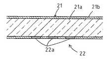
図4において、21aと21bは、一本の曲がり検出用光ファイバー21のコアとクラッドであり、曲がり検出部22には、コア21a内を通過してきた光をコア21a内に全反射せずに吸収してしまう光吸収部22aが、クラッド21bの特定方向(ここでは「下方向」)の部分に形成されている。
【0016】
すると、図5に示されるように、曲がり検出用光ファイバー21が上方向に曲げられると、コア21a内を通る光のうち光吸収部22aにあたる光の量(面積)が増えるので、曲がり検出用光ファイバー21の光伝達量が減少する。
【0017】
逆に、図6に示されるように、曲がり検出用光ファイバー21が下方向に曲げられると、コア21a内を通る光のうち光吸収部22aにあたる光の量(面積)が減少するので、曲がり検出用光ファイバー21の光伝達量が増加する。
【0018】
このような、光吸収部22aにおける曲がり検出用光ファイバー21の曲がり量と光伝達量とは一定の関係(例えば一次関数的関係)になるので、曲がり検出用光ファイバー21の光伝達量を検出することにより、光吸収部22aが形成されている曲がり検出部22部分の曲がり角度を検出することができる。
【0019】
したがって、挿入部1の軸線方向に間隔をあけて複数の曲がり検出部22が配列されている場合には、各曲がり検出部22間の間隔と検出された各曲がり検出部22の曲がり角度から、挿入部1全体の上下方向の屈曲状態を検出することができる。
【0020】
そして、図7の(A)に略示されるように、フレキシブルな帯状部材20に、上述のような曲がり検出部22と並列にさらに第2の曲がり検出部22′を配置して、横に並んだ二つの曲がり検出部22,22′の光伝達量を比較すれば、左右方向に捩れがない場合には双方の光伝達量に差がなく、左右方向の捩れ量に応じて双方の光伝達量の差が大きくなる。
【0021】
したがって、各曲がり検出部22,22′の光伝達量を計測してその計測値を比較することにより、曲がり検出部22,22′が配置された部分の左右方向の捩れ量を検出することができる。この原理は、米国特許第6127672号等に記載されている通りである。
【0022】
また、図7の(B)に示されるように、曲がり検出部22を一列に配置した二つの帯状部材20′,20″を直角の位置関係に配置しても、同様にして三次元の屈曲状態を検出することができる。
【0023】
そこで、複数の曲がり検出部22を挿入部1の軸線方向に所定の間隔で配置すると共に、それと並列に第2の複数の曲がり検出部22′を配置して、各曲がり検出部22,22′における光伝達量を検出、比較することにより挿入部1全体の三次元の屈曲状態を検出することができる。
【0024】
本実施例の可撓性内視鏡装置においては、図8に示されるように、帯状部材20の長手方向に一定の間隔で曲がり検出部22が位置するように、複数の曲がり検出用光ファイバー21を帯状部材20の表面側に取り付けると共に、表側の各曲がり検出部22の横に第2の曲がり検出部22′が並ぶように、帯状部材20の裏面側に第2の複数の曲がり検出用光ファイバー21′が取り付けられている。
【0025】
また、光吸収部22aが形成されていないシンプルなリファレンス用光ファイバー21Rを少なくとも一本配置して、各曲がり検出用光ファイバー21の光伝達量をリファレンス用光ファイバー21Rの光伝達量と比較することにより、曲がり検出用光ファイバー21の光伝達量に対する温度や経時劣化等の影響を除くことができる。
【0026】
図1は、上述の電子内視鏡を用いて、内視鏡観察画像と挿入部1の屈曲形状1′を表示する装置の全体構成を略示しており、固体撮像素子で撮像された内視鏡観察画像は、内視鏡プロセッサ7において処理されて観察画像表示用モニター8に表示される。
【0027】
また、曲がり検出用光ファイバー21の基端側に接続された光信号入出力装置30からの出力信号がコンピュータ40に送られ、そのコンピュータ40から出力される信号によって挿入部1の屈曲形状1′が挿入状態表示用モニター9に表示されるようになっている。
【0028】
図9は、そこに用いられている光信号入出力装置30の一例を示しており、一つの発光ダイオード31からの射出光が全部の光ファイバー21,21′,21Rに入射される。32は、発光ダイオード31の駆動回路である。
【0029】
そして、各光ファイバー21,21′,21Rの射出端毎に、光の強度レベルを電圧レベルに変換して出力するフォトダイオード33が配置されていて、各フォトダイオード33からの出力が、アンプ34で増幅されてからアナログ/デジタル変換器35によりデジタル信号化される。
【0030】
次いで、複数のアナログ/デジタル変換器35からパラレルに出力される信号が、パラレル/シリアル変換器36においてシリアル信号化されてコネクタ6から送り出される。
【0031】
そして、挿入部1が体内に挿入される際には、図1に示されるように、挿入部案内部材50が体内への入口部分(例えば口又は肛門)に取り付けられて、挿入部1はその挿入部案内部材50内を通される。
【0032】
挿入部案内部材50には、挿入部1の挿入長(即ち、挿入部案内部材50に対する通過長)Lを検出するためのエンコーダ60等が設けられていて、エンコーダ60からの出力信号がコンピュータ40に送られるようになっている。
【0033】
図10は、そのような挿入部案内部材50の一例を示しており、圧縮コイルスプリング52によって付勢された複数の回転自在な球状部材51が、挿入部1を周囲から挟み付ける状態に配置されている。
【0034】
したがって、各球状部材51は挿入部1の挿入長Lに比例して回転し、球状部材51のうちの一つに、挿入部1の挿入長Lに比例する数のパルスを出力するエンコーダ60が連結されている。
【0035】
ただし、挿入部案内部材50における挿入部1の挿入長Lの検出は、例えば特開昭56−97429号や特開昭60−217326号等に記載されているように、挿入部1の表面からの光反射等を利用してもよく、その他の手段によっても差し支えない。
【0036】
このようにして、図1に示されるように、コンピュータ40には光信号入出力装置30(内視鏡プロセッサ7経由)からとエンコーダ60から、挿入部1の屈曲状態検出信号と挿入長検出信号が入力し、挿入部案内部材50の画像50′と、挿入部1の屈曲形状1′とが挿入状態表示用モニター9に表示される。
【0037】
図11は、そのような画像を挿入状態表示用モニター9に表示させるためのコンピュータ40のソフトウェアの内容の概略を示すフロー図であり、図中のSは処理ステップを示す。
【0038】
挿入状態表示用モニター9に正確な屈曲状態を表示させるためには、まず挿入部1を体内に挿入する前に、実際に用いられる内視鏡の挿入部1の屈曲角度と曲がり検出用光ファイバー21から得られる検出信号とを対比させ、後述する挿入部1の屈曲形状座標系(xyz)と臓器形状座標系(XYZ)の両座標が相関関係を持つように予めキャリブレーションを行っておくことが好ましい(S1)。臓器形状座標系(XYZ)は、例えば、直立する人体を正面から見た状態で、左右方向をX軸、上下方向をZ軸、奥行きをY軸のように定めればよい。
【0039】
そして、挿入部1を体内に挿入したら、エンコーダ60から挿入部1の挿入長Lの検出信号を入力して(S2)、挿入部案内部材50が挿入部1のどの位置にあるかを算出する(S3)。
【0040】
次いで、各曲がり検出用光ファイバー21からの検出信号V1…を入力して(S4)、その検出信号V1…をキャリブレーションデータに基づいて曲がり角度に変換し(S5)、各曲がり検出部22部分の曲がり角度から、三次元座標上における各曲がり検出部22の位置を算出する(S6)。
【0041】
そして、挿入状態表示用モニター9において挿入部案内部材50の像50′の位置を動かさないようにして、各曲がり検出部22の位置を滑らかに結んで表示することにより挿入部1の屈曲状態が表示され(S7)、S2へ戻ってS2〜S7を繰り返す。
【0042】
このような表示を行う際、挿入状態表示用モニター9における表示は二次元画像であるが、各曲がり検出部22の位置についての三次元データが得られているので、「上方向」だけでなく任意の回転方向における挿入部1の屈曲状態を表示させることができる。
【0043】
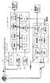
図2は、図1において図示が省略されているコンピュータ40と内視鏡プロセッサ7の各々の内部構成を含む装置の全体構成を示しており、既に説明されている部分については符号のみを付してその説明は省略する。
【0044】
コンピュータ40には、中央演算装置(CPU)41の他、外部との信号の入出力を行う入出力回路42,43、外部から画像信号を受け取る画像キャプチャ44、ソフトウェア及びその他の各種データを記憶する記憶装置45、映像表示のためのビデオ表示回路46等の回路が配置されていて、座標算出47及び合成画像構築48等はソフトウェアの実行によって行われる。
【0045】
このうち、記憶装置45には、内視鏡が挿入される対象となる各種臓器の雛形形状が記憶されており、入出力回路42に接続された指示入力装置99からの指示信号入力によって、適宜の臓器形状100を挿入部1の屈曲形状1′と共に挿入状態表示用モニター9に表示させることができる。
【0046】
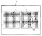
そのような挿入状態表示用モニター9への表示は、図1に示されるように臓器形状100と挿入部1の屈曲形状1′とを重ね合わせたものだけでもよいが、図12に示されるように、そのような重ね合わせ画像(二次元像)を、挿入部1の屈曲形状1′(三次元像を二次元表示したもの)の横に並べて表示してもよい。
【0047】
図2に戻って、内視鏡プロセッサ7には、システム制御回路71と記憶装置72等の他、内視鏡のライトガイドに照明光を供給するための光源部73等が併設されている。
【0048】
また、プリプロセス回路74及び信号処理部75を経て出力される内視鏡観察画像の映像信号が、ビデオ表示回路76から、観察画像表示用モニター8だけでなくコンピュータ40の画像キャプチャ44にも出力されるようになっている。
【0049】
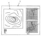
その結果、図13に示されるように、挿入状態表示用モニター9に、挿入部1の屈曲形状1′のみの画像と、臓器形状100と挿入部1の屈曲形状1′とを重ね合わせた画像と内視鏡観察画像Vとを並べて表示することもできる。
【0050】
しかし、一般に生体の臓器の形状と大きさは人さまざまなので、標準的な雛形の臓器形状では、実際に内視鏡が挿入されている臓器の形状と一致しない場合が多い。
【0051】
そこで、この実施例においては、内視鏡の挿入部1の先端位置が現在どの部位にあるかを内視鏡観察画像から術者が認識し易い複数箇所で、臓器形状100が表示されている画面上に術者がマークをし、その情報に基づいて臓器形状100の位置と形状を補正して、挿入部1の屈曲形状1′と臓器形状100との関係が正確に表示されるようにしている。
【0052】
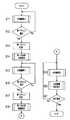
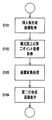
図14〜図17は、そのような処理を実行するためのコンピュータ40のソフトウェアの内容を示すフロー図であり、そこでは先ず、図18に示されるように、体内への内視鏡挿入に合わせて、内視鏡の挿入部1の屈曲形状1′をプロットしていく(S11)。これは前出のS1〜S7のサブルーチン処理によって行われる。
【0053】
そして、内視鏡の挿入部1の先端位置を内視鏡観察画像から術者が容易に認識し易い第一のポイントA(例えば噴門部)に来たら、指示入力装置99によって、図19に示されるように、その位置に識別マークを入力する。
【0054】
指示入力装置99は、マウス、キーボード、又は内視鏡操作ボタンにカーソル移動機能を割り当てたもの等でもよく、予め第一のポイントAを決めておけば、内視鏡観察画面でその部位に来たときにリターンキーを押すなどの簡略な操作にすることもできる(S12)。
【0055】
第一のポイントAが選択されるまで挿入部1の屈曲形状1′のプロットを繰り返す。そして、第一のポイントAが選択されたら、その識別マークの座標位置を記憶する(S13)。
【0056】
なお、挿入部1の屈曲形状座標系は(xyz)三次元座標系であり、臓器形状100も三次元要素で作成されているが、モニター表示は処理の簡略化と高速化の都合で二次元画像表示になっている。
【0057】
次いで、第一のポイントAに於ける座標取得を行って、座標変換サブルーチン処理(S141〜S144)を行い、第一のポイントAに於ける合成画像表示を行う(S14)。
【0058】
サブルーチンS141〜S143では以下の座標変換処理が行われる。
挿入部1の屈曲形状座標系(xyz)と臓器形状座標系(XYZ)は座標系が異なるので、第一のポイントA点で一致するように臓器形状座標系(XYZ)を平行移動座標変換する。
【0059】
臓器形状座標系の点A(XA ,YA ,ZA )、
挿入部1の屈曲形状座標系における挿入部先端位置をa(xa ,ya ,za )とし、
点Aと点aの座標値の偏差をtx ,ty ,tz とする。
【0060】
すると、点A(XA ,YA ,ZA )をtx ,ty ,tzだけ平行移動することにより、点a(xa ,ya ,za )と合致するので、この関係は次式で表すことができる。
【0061】
【数1】
そこで、S144において、第一のポイントAと、それに合致させた挿入部1の屈曲形状1′とを挿入状態表示用モニター9に重ね合わせて合成表示する。その結果、この時点では、挿入部1の屈曲形状1′と第一のポイントAのマークが挿入状態表示用モニター9に表示される。
【0063】
次いで、内視鏡の挿入部1の挿入をさらに進める(S15)。挿入部1の屈曲形状座標と臓器形状座標は第一のポイントA点に於いて一致するので、その近傍では、術者の設定誤差以外に挿入部1の屈曲形状と臓器形状の誤差はない。
【0064】
挿入部1がさらに体内に挿入され、内視鏡の挿入部1の先端位置を内視鏡観察画像から術者が容易に認識し易い例えば幽門部等において、第二のポイントB(挿入部1の屈曲形状座標系上のポイント)を指示入力装置99により設定し(S16)、臓器座標系上の第二のポイントB’(臓器形状座標上の幽門部)の座標取得を行う(S17)。
【0065】
次いで、座標変換サブルーチン処理(S181〜S184)を行って、図20に示されるように、挿入部1の先端位置から指定された第二のポイントBが臓器形成側の点B’と一致するように座標変換を行う(S18)。
【0066】
第一のポイントAは確定しているわけであるから、第一のポイントAを基準点として点B’がB点に移動するように生体臓器形状座標(XYZ)をXYZ座標軸に対してスケール変換を行うことにより、座標変換が成し遂げられる。
【0067】
ここで、X軸、Y軸、Z軸に対するスケール変換率をそれぞれd,e,f とし、図20においてY軸を例にとると、基準となる第一のポイントAからB点までの距離をYA-Bとし、第一のポイントAからB’点までの距離をYA-B’とすると、Y軸に対するスケール変換率eは、
e = YA-B /YA-B’
であり、同様にしてX軸,Z軸に対するスケール変換率d,fも求めることができる。
【0068】
挿入部1の屈曲形状座標のB点(xB ,yB ,zB )に臓器形状座標の点B’(XB' ,YB' ,ZB' )を一致させるときの変換マトリックスはスケール変換率d,e,f を用いて、
【0069】
【数2】
と表すことができる。
そこで、図21に示されるように、第二のポイントB’をBに合致させた挿入部1の屈曲形状1′を臓器形状画面に重ね合わせて表示する(S184)。
【0071】
そして、前出のS1〜S7のサブルーチン処理によって、さらに挿入部1の屈曲形状1′のプロットを続行する(S19)。
ただし、挿入部1の屈曲形状座標と臓器形状座標はすでにほとんど座標が一致しているが、元の臓器形状と実際の生体部位は患者の固体差でその形状が異なることがある。そこで、合成画像補正サブルーチン(S201〜S204)によって、より実際的な自然な状態に合成画像を修正する(S20)。
【0072】
ここでは、まずその位置に於ける挿入部1の屈曲形状の座標を取得し(S201)、XYZ軸上の臓器形状の輪郭座標値を取得して最大値と最小値を求める(S202)。
【0073】
そして、挿入部1に配置された曲がり検出部22の座標値が臓器形状輪郭の最大値と最小値以内にあれば、挿入部1の屈曲形状は臓器形状輪郭内と判断してS21に進む(S203)。
【0074】
曲がり検出部22の座標値が臓器形状輪郭の最大値又は最小値から外れた場合は、AB点を結ぶ線分を固定軸として臓器形状輪郭から外れた曲がり検出部22の座標の臓器形状輪郭との差分を吸収するようにスケール変換を行う(S204)。
【0075】
具体的には、AB点を結ぶ線分が新しい座標軸となるように回転座標変換を行った後に、新しい座標軸に対してスケール変換を行ってセンサ位置が臓器形状輪郭の内側に位置するように画像補正を行ってから、S21に進む。
【0076】
このようにして、挿入部1の挿入対象である臓器の形状を挿入部1の屈曲形状1′と共に挿入状態表示用モニター9に表示させ、画面に表示されているその臓器形状を外部入力に応じて実際の臓器形状に近い形状に補正して、X線透視等を併用することなく内視鏡検査を安全に行うことができる。
【0077】
なお、患者の観察部位の形状データを予めCTスキャナ等のような臓器形状採取手段を用いて取得しておき、臓器の雛形形状に代えて、患者自身の臓器形状図と内視鏡挿入部1の屈曲形状を合成して画像表示してもよい。その場合には、CTスキャナ画像等から画像処理によって輪郭抽出した組織形状画像と合成すると分かり易い。
【0078】
また、上記実施例では合成画像表示を一視点方向から表示するものとして説明したが、合成画像表示は正面像と横からの二方向の画像を同時に表示してもよく、また三次元画像表示にしてもよい。
【0079】
また、臓器としては胃を例にとったが、予め各種の臓器データを準備しておいてその中から必要な臓器形状を利用すればよい。さらに臓器形状との合成画像を内視鏡画像と同時に印刷することにより、どの部位の画像であるかが後からでも容易に判別できるようになり、検査後の診断や検討の際に有効である。
【0080】
【発明の効果】
本発明によれば、内視鏡の挿入部の挿入対象である臓器の形状を挿入部の屈曲状態と共にモニター画面に表示させ、モニター画面に表示されているその臓器の形状を外部入力に応じて実際の臓器形状に近い形状に補正することができるので、内視鏡が挿入されている臓器の形状とその内部における内視鏡の状態を一目で確認することができ、X線透視等を併用することなく内視鏡検査を安全に行うことができる。
【図面の簡単な説明】
【図1】本発明の実施例の可撓性内視鏡のモニター装置の使用状態の全体構成略示図である。
【図2】本発明の実施例の可撓性内視鏡のモニター装置の全体構成を示すブロック図である。
【図3】本発明の実施例の電子内視鏡の挿入部の先端付近の斜視図である。
【図4】本発明の実施例に用いられる曲がり検出用光ファイバーの曲がり検出部の略示断面図である。
【図5】本発明の実施例に用いられる曲がり検出用光ファイバーの曲がり検出部が屈曲した状態の略示断面図である。
【図6】本発明の実施例に用いられる曲がり検出用光ファイバーの曲がり検出部が逆方向に屈曲した状態の略示断面図である。
【図7】本発明の実施例に用いられる曲がり検出用光ファイバーによる三次元の屈曲状態検出の原理を説明するための略示図である。
【図8】本発明の実施例の曲がり検出用光ファイバーが取り付けられた帯状部材の平面図である。
【図9】本発明の実施例の光信号入出力装置の回路図である。
【図10】本発明の実施例の挿入部案内部材の正面断面図である。
【図11】本発明の実施例のコンピュータのソフトウェアの内容を略示するフロー図である。
【図12】本発明の実施例のモニター画面表示の一例を示す略示図である。
【図13】本発明の実施例のモニター画面表示の一例を示す略示図である。
【図14】本発明の実施例のコンピュータのソフトウェアの内容を略示するフロー図である。
【図15】本発明の実施例のコンピュータのソフトウェアの内容を略示するフロー図である。
【図16】本発明の実施例のコンピュータのソフトウェアの内容を略示するフロー図である。
【図17】本発明の実施例のコンピュータのソフトウェアの内容を略示するフロー図である。
【図18】本発明の実施例の動作を説明するための座標図である。
【図19】本発明の実施例の動作を説明するための座標図である。
【図20】本発明の実施例の動作を説明するための座標図である。
【図21】本発明の実施例の動作を説明するための座標図である。
【符号の説明】
1 挿入部
1′挿入部の屈曲形状
9 挿入状態表示用モニター
21 曲がり検出用光ファイバー
22 曲がり検出部
30 光信号入出力装置
40 コンピュータ
99 指示入力装置
A 第一のポイント
B 第二のポイント
100 臓器形状[0001]
BACKGROUND OF THE INVENTION
The present invention relates to a monitor device for a flexible endoscope for observing the inside of a gastrointestinal tract or the like.
[0002]
[Prior art]
An image of the mucosal surface in the internal organ can be observed with an endoscope. However, since the shape of the organ into which the endoscope is inserted cannot be known with the endoscope, it is difficult for doctors who have considerable experience to accurately determine the insertion state and locate the detected lesion. There are many cases.
[0003]
Therefore, when it is necessary to confirm the insertion state of the endoscope, the endoscope apparatus set is carried to the X-ray room, and an endoscopic examination is performed while seeing through the X-ray.
[0004]
[Problems to be solved by the invention]
However, performing endoscopy under X-ray fluoroscopy not only causes yellowing of the optical fiber bundle used in the endoscope and adverse effects on the health of patients directly exposed to X-rays, Since doctors who perform endoscopic operations are repeatedly exposed to X-rays, their health has a serious adverse effect.
[0005]
Accordingly, the present invention provides a flexible endoscope monitor that can safely confirm the shape of the organ into which the endoscope is inserted and the state of the endoscope inside the organ without using X-ray fluoroscopy. An object is to provide an apparatus.
[0006]
[Means for Solving the Problems]
In order to achieve the above object, the monitor device for a flexible endoscope of the present invention is a flexible endoscope provided with bending state display means for detecting the bending state of the flexible insertion portion and displaying it on the monitor screen. In an endoscopic monitoring device, organ shape display means for displaying the shape of an organ to be inserted in the insertion portion on the monitor screen together with the bending state of the insertion portion, and external input of the shape of the organ displayed on the monitor screen And organ shape correcting means for correcting according to the above.
[0007]
The organ shape correcting means may correct the display position and shape of the organ shape displayed on the monitor screen according to an external input.
Further, the organ shape display means may read out a pre-prepared organ model shape from the storage means and display it on the monitor screen, or may display the shape of the actual organ to be inserted into the insertion unit in advance. Organ shape collecting means for collecting may be provided, and the organ shape collected by the organ shape collecting means may be displayed on the monitor screen by the organ shape display means.
[0008]
As the bending state detection part of the bending state display means, a plurality of flexible bending detection optical fibers in which a bending detection part in which the amount of transmitted light changes corresponding to the magnitude of the bent angle is provided, The bending detection unit may be arranged in a distributed manner in the insertion unit, and the bending state of the insertion unit may be detected based on detection values obtained from a plurality of bending detection units. The bending shape may be displayed by displaying the three-dimensional data two-dimensionally.
[0009]
DETAILED DESCRIPTION OF THE INVENTION
Embodiments of the present invention will be described with reference to the drawings.
FIG. 3 shows the distal end portion of the
[0010]
On the upper surface of the
[0011]
The plurality of bend detection
[0012]
For example, about 10 to 30
[0013]
The
[0014]
Such a
[0015]
In FIG. 4,
[0016]
Then, as shown in FIG. 5, when the bending detection
[0017]
On the contrary, as shown in FIG. 6, when the bending detection
[0018]
Since the bending amount of the bending detection
[0019]
Therefore, when a plurality of
[0020]
Then, as schematically shown in FIG. 7A, a
[0021]
Therefore, by measuring the light transmission amount of each bending
[0022]
Further, as shown in FIG. 7B, even if the two belt-
[0023]
Therefore, a plurality of
[0024]
In the flexible endoscope apparatus of the present embodiment, as shown in FIG. 8, a plurality of bending detection
[0025]
Further, by arranging at least one simple reference
[0026]
FIG. 1 schematically shows an overall configuration of an apparatus that displays an endoscopic observation image and a
[0027]
Further, an output signal from the optical signal input /
[0028]
FIG. 9 shows an example of the optical signal input /
[0029]
A
[0030]
Next, signals output in parallel from the plurality of analog /
[0031]
When the
[0032]
The insertion
[0033]
FIG. 10 shows an example of such an insertion
[0034]
Accordingly, each
[0035]
However, the insertion length L of the
[0036]
In this way, as shown in FIG. 1, the
[0037]
FIG. 11 is a flowchart showing an outline of the contents of the software of the
[0038]
In order to display an accurate bending state on the insertion
[0039]
When the
[0040]
Next, detection signals V1 ... From the respective bending detection
[0041]
The insertion state display monitor 9 does not move the position of the
[0042]
When such a display is performed, the display on the insertion state display monitor 9 is a two-dimensional image, but since three-dimensional data on the position of each bending
[0043]
FIG. 2 shows the overall configuration of the apparatus including the internal configurations of the
[0044]
In addition to the central processing unit (CPU) 41, the
[0045]
Among these, the
[0046]
Such an indication on the insertion state display monitor 9 may be only the one in which the
[0047]
Returning to FIG. 2, the
[0048]
The video signal of the endoscopic observation image output through the
[0049]
As a result, as shown in FIG. 13, an image of only the
[0050]
However, since the shape and size of a living organ generally varies from person to person, the standard model organ shape often does not match the shape of the organ into which the endoscope is actually inserted.
[0051]
Therefore, in this embodiment, the
[0052]
FIGS. 14 to 17 are flowcharts showing the contents of the software of the
[0053]
When the position of the distal end of the
[0054]
The
[0055]
The plot of the bent shape 1 'of the
[0056]
Note that the bent shape coordinate system of the
[0057]
Next, coordinates are acquired at the first point A, coordinate conversion subroutine processing (S141 to S144) is performed, and a composite image is displayed at the first point A (S14).
[0058]
In the subroutines S141 to S143, the following coordinate conversion processing is performed.
Since the coordinate system of the bent shape coordinate system (xyz) and the organ shape coordinate system (XYZ) of the
[0059]
Point A (XA, YA, ZA) in the organ shape coordinate system,
The insertion portion tip position in the bending shape coordinate system of the
Deviations between the coordinate values of point A and point a are tx, ty, and tz.
[0060]
Then, since the point A (XA, YA, ZA) is translated by tx, ty, tz to coincide with the point a (xa, ya, za), this relationship can be expressed by the following equation.
[0061]
[Expression 1]
Therefore, in S144, the first point A and the bent shape 1 'of the
[0063]
Next, the insertion of the
[0064]
The
[0065]
Next, coordinate transformation subroutine processing (S181 to S184) is performed, and as shown in FIG. 20, the second point B designated from the distal end position of the
[0066]
Since the first point A is fixed, the biological organ shape coordinates (XYZ) are scaled with respect to the XYZ coordinate axes so that the point B ′ moves to the B point with the first point A as a reference point. By performing the above, coordinate transformation is achieved.
[0067]
Here, the scale conversion rates for the X, Y, and Z axes are d, e, and f, respectively, and taking the Y axis as an example in FIG. 20, the distance from the first point A to the B point as a reference is obtained. Assuming that YA-B and the distance from the first point A to the point B ′ is YA-B ′, the scale conversion rate e with respect to the Y axis is
e = YA-B / YA-B '
Similarly, the scale conversion rates d and f with respect to the X axis and the Z axis can also be obtained.
[0068]
The transformation matrix when the point B ′ (XB ′, YB ′, ZB ′) of the organ shape coordinates is made to coincide with the point B (xB, yB, zB) of the bent shape coordinates of the
[0069]
[Expression 2]
It can be expressed as.
Therefore, as shown in FIG. 21, the
[0071]
Then, further plotting of the bent shape 1 'of the
However, the bent shape coordinates and the organ shape coordinates of the
[0072]
Here, first, the coordinates of the bent shape of the
[0073]
If the coordinate value of the bending
[0074]
When the coordinate value of the
[0075]
Specifically, after rotating coordinate transformation is performed so that the line segment connecting the AB points becomes a new coordinate axis, scale transformation is performed on the new coordinate axis so that the sensor position is located inside the organ shape contour. After performing the correction, the process proceeds to S21.
[0076]
In this way, the shape of the organ to be inserted into the
[0077]
It should be noted that the shape data of the observation site of the patient is acquired in advance by using an organ shape collection means such as a CT scanner, and instead of the template shape of the organ, the patient's own organ shape diagram and
[0078]
In the above embodiment, the composite image display is described as being displayed from one viewpoint direction. However, the composite image display may be a front image and a two-direction image displayed simultaneously, or a three-dimensional image display. May be.
[0079]
Further, although the stomach is taken as an example of an organ, various organ data may be prepared in advance and a necessary organ shape may be used. Furthermore, by printing a composite image with the organ shape at the same time as the endoscopic image, it is possible to easily determine which part of the image is later, which is effective for post-examination diagnosis and examination. .
[0080]
【The invention's effect】
According to the present invention, the shape of the organ to be inserted into the insertion portion of the endoscope is displayed on the monitor screen together with the bending state of the insertion portion, and the shape of the organ displayed on the monitor screen is displayed according to an external input. Since it can be corrected to a shape close to the actual organ shape, the shape of the organ in which the endoscope is inserted and the state of the endoscope in the inside can be confirmed at a glance. Endoscopic examination can be performed safely without doing.
[Brief description of the drawings]
FIG. 1 is a schematic diagram showing the overall configuration of a use state of a monitor device for a flexible endoscope according to an embodiment of the present invention.
FIG. 2 is a block diagram illustrating an overall configuration of a monitor device for a flexible endoscope according to an embodiment of the present invention.
FIG. 3 is a perspective view of the vicinity of the distal end of the insertion portion of the electronic endoscope according to the embodiment of the present invention.
FIG. 4 is a schematic cross-sectional view of a bending detection portion of a bending detection optical fiber used in an embodiment of the present invention.
FIG. 5 is a schematic cross-sectional view showing a bent state of a bending detection portion of a bending detection optical fiber used in an embodiment of the present invention.
FIG. 6 is a schematic cross-sectional view of a state in which a bend detection unit of a bend detection optical fiber used in an embodiment of the present invention is bent in a reverse direction.
FIG. 7 is a schematic diagram for explaining the principle of detecting a three-dimensional bending state using a bending detection optical fiber used in an embodiment of the present invention.
FIG. 8 is a plan view of a belt-like member to which a bending detection optical fiber according to an embodiment of the present invention is attached.
FIG. 9 is a circuit diagram of an optical signal input / output device according to an embodiment of the present invention.
FIG. 10 is a front sectional view of the insertion portion guide member according to the embodiment of the present invention.
FIG. 11 is a flowchart schematically showing the contents of software of a computer according to an embodiment of the present invention.
FIG. 12 is a schematic diagram showing an example of a monitor screen display according to the embodiment of the present invention.
FIG. 13 is a schematic diagram showing an example of a monitor screen display according to the embodiment of the present invention.
FIG. 14 is a flowchart schematically showing the contents of software of a computer according to an embodiment of the present invention.
FIG. 15 is a flowchart schematically showing the contents of software of a computer according to an embodiment of the present invention.
FIG. 16 is a flowchart schematically showing the contents of software of a computer according to an embodiment of the present invention.
FIG. 17 is a flowchart schematically showing the contents of software of a computer according to an embodiment of the present invention.
FIG. 18 is a coordinate diagram for explaining the operation of the embodiment of the present invention.
FIG. 19 is a coordinate diagram for explaining the operation of the embodiment of the present invention.
FIG. 20 is a coordinate diagram for explaining the operation of the embodiment of the present invention.
FIG. 21 is a coordinate diagram for explaining the operation of the embodiment of the present invention.
[Explanation of symbols]
DESCRIPTION OF
Claims (3)
Translated fromJapanese上記臓器形状表示手段は、予め準備されている臓器の雛形形状を記憶手段から読み出して上記モニター画面に表示し、
上記臓器形状補正手段は、外部から手動入力される上記挿入部の複数の先端位置情報に基づいて、上記モニター画面に表示されている臓器形状の表示位置と形状を補正する
ことを特徴とする可撓性内視鏡のモニター装置。A bending state display means for detecting a bent state of the flexible insertion portion and displays it on the monitorscreen, organs for displaying the shape of the organ is the insertion target of the insertion portion together with the flexion of the insertion portion to the monitor screen Ina monitor device for a flexible endoscope provided with shape display means and organ shape correction means for correcting the shape of the organ displayed on the monitor screen according to an external input,
The organ shape display means reads out a template shape of an organ prepared in advance from the storage means and displays it on the monitor screen,
The organ shape correcting means corrects the display position and shape of the organ shape displayed on the monitor screen based on a plurality of tip position information of the insertion portion manually input from the outside. Flexible endoscope monitor device.
Priority Applications (1)
| Application Number | Priority Date | Filing Date | Title |
|---|---|---|---|
| JP2002024885AJP4017877B2 (en) | 2002-02-01 | 2002-02-01 | Flexible endoscope monitor device |
Applications Claiming Priority (1)
| Application Number | Priority Date | Filing Date | Title |
|---|---|---|---|
| JP2002024885AJP4017877B2 (en) | 2002-02-01 | 2002-02-01 | Flexible endoscope monitor device |
Publications (2)
| Publication Number | Publication Date |
|---|---|
| JP2003225195A JP2003225195A (en) | 2003-08-12 |
| JP4017877B2true JP4017877B2 (en) | 2007-12-05 |
Family
ID=27747198
Family Applications (1)
| Application Number | Title | Priority Date | Filing Date |
|---|---|---|---|
| JP2002024885AExpired - LifetimeJP4017877B2 (en) | 2002-02-01 | 2002-02-01 | Flexible endoscope monitor device |
Country Status (1)
| Country | Link |
|---|---|
| JP (1) | JP4017877B2 (en) |
Cited By (1)
| Publication number | Priority date | Publication date | Assignee | Title |
|---|---|---|---|---|
| US20210327294A1 (en)* | 2018-09-03 | 2021-10-21 | Kurume University | Controller, method for manufacturing controller, simulated experience system, and simulated experience method |
Families Citing this family (13)
| Publication number | Priority date | Publication date | Assignee | Title |
|---|---|---|---|---|
| JP2008173397A (en)* | 2007-01-22 | 2008-07-31 | Olympus Corp | Endoscope system |
| JP5085142B2 (en)* | 2007-01-22 | 2012-11-28 | オリンパス株式会社 | Endoscope system and method for operating apparatus for detecting shape of endoscope insertion portion used therefor |
| WO2008094949A2 (en) | 2007-01-29 | 2008-08-07 | Neoguide Systems, Inc. | System for controlling an instrument using shape sensors |
| JP5259340B2 (en)* | 2008-10-28 | 2013-08-07 | オリンパスメディカルシステムズ株式会社 | Medical equipment |
| EP2358259A4 (en)* | 2008-11-21 | 2014-08-06 | Mayo Foundation | COLOSCOPY MONITORING AND EVALUATION SYSTEM |
| WO2010122823A1 (en) | 2009-04-20 | 2010-10-28 | オリンパスメディカルシステムズ株式会社 | Subject internal examination system |
| JP6205125B2 (en)* | 2012-12-11 | 2017-09-27 | オリンパス株式会社 | Endoscope device insertion support information detection system and endoscope device |
| CN105491936B (en) | 2013-08-28 | 2017-08-22 | 奥林巴斯株式会社 | Capsule-type endoscope system |
| WO2015049962A1 (en)* | 2013-10-02 | 2015-04-09 | オリンパスメディカルシステムズ株式会社 | Endoscope system |
| JP2015223440A (en)* | 2014-05-29 | 2015-12-14 | オリンパス株式会社 | Multi-point detection fiber sensor and insertion device equipped with multi-point detection fiber sensor |
| EP3095377A4 (en)* | 2014-06-10 | 2017-09-13 | Olympus Corporation | Endoscope system and endoscope system operation method |
| WO2018230099A1 (en) | 2017-06-15 | 2018-12-20 | オリンパス株式会社 | Endoscope system, and method for operating endoscope system |
| US20230169669A1 (en)* | 2020-04-09 | 2023-06-01 | Nec Corporation | Endoscope insertion assistance apparatus, method and non-transitory computer-readable medium storing program thereof |
- 2002
- 2002-02-01JPJP2002024885Apatent/JP4017877B2/ennot_activeExpired - Lifetime
Cited By (2)
| Publication number | Priority date | Publication date | Assignee | Title |
|---|---|---|---|---|
| US20210327294A1 (en)* | 2018-09-03 | 2021-10-21 | Kurume University | Controller, method for manufacturing controller, simulated experience system, and simulated experience method |
| US12046158B2 (en)* | 2018-09-03 | 2024-07-23 | Kurume University | Controller, method for manufacturing controller, simulated experience system, and simulated experience method |
Also Published As
| Publication number | Publication date |
|---|---|
| JP2003225195A (en) | 2003-08-12 |
Similar Documents
| Publication | Publication Date | Title |
|---|---|---|
| JP6389136B2 (en) | Endoscopy part specifying device, program | |
| US10765308B2 (en) | Method and apparatus for tracking in a medical procedure | |
| JP4017877B2 (en) | Flexible endoscope monitor device | |
| CN114795472B (en) | Apparatus and method for tracking the position of an endoscope within a patient's body | |
| US8767057B2 (en) | Image processing device, image processing method, and program | |
| US7901348B2 (en) | Catheterscope 3D guidance and interface system | |
| US8204576B2 (en) | Medical guiding system | |
| US10631826B2 (en) | Medical apparatus, medical-image generating method, and recording medium on which medical-image generating program is recorded | |
| KR20200007896A (en) | Biopsy Devices and Systems | |
| JP2004321796A (en) | Computer-assisted three-dimensional image forming method for capsule endoscope device, wireless endoscope device, and medical technology device | |
| JPS60217326A (en) | Endoscope | |
| JP4436638B2 (en) | Endoscope apparatus and endoscope insertion operation program | |
| JP4334839B2 (en) | Endoscope observation device | |
| JP3943353B2 (en) | Flexible ultrasound endoscope device | |
| JPH0330089Y2 (en) | ||
| JP3898910B2 (en) | Flexible endoscope device | |
| JP2003038492A (en) | Ultrasound endoscope device | |
| JP6464110B2 (en) | Endoscope shape grasp system | |
| JP3920603B2 (en) | Flexible endoscope device | |
| JP3911139B2 (en) | Flexible endoscope device | |
| JPS62221332A (en) | Endoscope image diagnostic apparatus | |
| JP4694062B2 (en) | Flexible electronic endoscope device | |
| WO2023089715A1 (en) | Image display device, image display method, and recording medium |
Legal Events
| Date | Code | Title | Description |
|---|---|---|---|
| A621 | Written request for application examination | Free format text:JAPANESE INTERMEDIATE CODE: A621 Effective date:20050126 | |
| A977 | Report on retrieval | Free format text:JAPANESE INTERMEDIATE CODE: A971007 Effective date:20070625 | |
| A131 | Notification of reasons for refusal | Free format text:JAPANESE INTERMEDIATE CODE: A131 Effective date:20070628 | |
| A521 | Written amendment | Free format text:JAPANESE INTERMEDIATE CODE: A523 Effective date:20070821 | |
| TRDD | Decision of grant or rejection written | ||
| A01 | Written decision to grant a patent or to grant a registration (utility model) | Free format text:JAPANESE INTERMEDIATE CODE: A01 Effective date:20070913 | |
| A61 | First payment of annual fees (during grant procedure) | Free format text:JAPANESE INTERMEDIATE CODE: A61 Effective date:20070919 | |
| R150 | Certificate of patent or registration of utility model | Free format text:JAPANESE INTERMEDIATE CODE: R150 | |
| FPAY | Renewal fee payment (event date is renewal date of database) | Free format text:PAYMENT UNTIL: 20100928 Year of fee payment:3 | |
| FPAY | Renewal fee payment (event date is renewal date of database) | Free format text:PAYMENT UNTIL: 20100928 Year of fee payment:3 | |
| FPAY | Renewal fee payment (event date is renewal date of database) | Free format text:PAYMENT UNTIL: 20110928 Year of fee payment:4 | |
| FPAY | Renewal fee payment (event date is renewal date of database) | Free format text:PAYMENT UNTIL: 20110928 Year of fee payment:4 | |
| FPAY | Renewal fee payment (event date is renewal date of database) | Free format text:PAYMENT UNTIL: 20120928 Year of fee payment:5 |