JP4015659B2 - Articulated stent - Google Patents
Articulated stentDownload PDFInfo
- Publication number
- JP4015659B2 JP4015659B2JP2004363421AJP2004363421AJP4015659B2JP 4015659 B2JP4015659 B2JP 4015659B2JP 2004363421 AJP2004363421 AJP 2004363421AJP 2004363421 AJP2004363421 AJP 2004363421AJP 4015659 B2JP4015659 B2JP 4015659B2
- Authority
- JP
- Japan
- Prior art keywords
- stent
- link
- width
- segment
- longitudinal
- Prior art date
- Legal status (The legal status is an assumption and is not a legal conclusion. Google has not performed a legal analysis and makes no representation as to the accuracy of the status listed.)
- Expired - Lifetime
Links
- 238000006073displacement reactionMethods0.000claimsdescription5
- 238000005452bendingMethods0.000claims3
- 210000004204blood vesselAnatomy0.000description11
- 238000002513implantationMethods0.000description5
- 229910003460diamondInorganic materials0.000description3
- 239000010432diamondSubstances0.000description3
- 229910000619316 stainless steelInorganic materials0.000description2
- 241001465754MetazoaSpecies0.000description2
- 238000002399angioplastyMethods0.000description2
- 239000000560biocompatible materialSubstances0.000description2
- 210000004351coronary vesselAnatomy0.000description2
- PCHJSUWPFVWCPO-UHFFFAOYSA-NgoldChemical compound[Au]PCHJSUWPFVWCPO-UHFFFAOYSA-N0.000description2
- 229910052737goldInorganic materials0.000description2
- 239000010931goldSubstances0.000description2
- 229910001220stainless steelInorganic materials0.000description2
- 239000010935stainless steelSubstances0.000description2
- 229910052715tantalumInorganic materials0.000description2
- GUVRBAGPIYLISA-UHFFFAOYSA-Ntantalum atomChemical compound[Ta]GUVRBAGPIYLISA-UHFFFAOYSA-N0.000description2
- 241000282412HomoSpecies0.000description1
- 230000002159abnormal effectEffects0.000description1
- 230000001939inductive effectEffects0.000description1
- 238000000034methodMethods0.000description1
- 238000012986modificationMethods0.000description1
- 230000004048modificationEffects0.000description1
- HLXZNVUGXRDIFK-UHFFFAOYSA-Nnickel titaniumChemical compound[Ti].[Ti].[Ti].[Ti].[Ti].[Ti].[Ti].[Ti].[Ti].[Ti].[Ti].[Ni].[Ni].[Ni].[Ni].[Ni].[Ni].[Ni].[Ni].[Ni].[Ni].[Ni].[Ni].[Ni].[Ni]HLXZNVUGXRDIFK-UHFFFAOYSA-N0.000description1
- 229910001000nickel titaniumInorganic materials0.000description1
- 230000002093peripheral effectEffects0.000description1
- 239000012781shape memory materialSubstances0.000description1
Images


Landscapes
- Media Introduction/Drainage Providing Device (AREA)
Description
Translated fromJapanese本発明の分野及び背景
本発明は、開通性を維持するために生きた動物又はヒトの体管内にバルーン血管形成術の一部として移植されるステントに関する。特に、本発明は、曲った部分をもつ血管を通してのデリバリー又はその内の移植のための関節のある血管内ステントに関する。Field and Background of the Invention The present invention relates to a stent that is implanted as part of a balloon angioplasty into a living animal or human body vessel to maintain patency. In particular, the present invention relates to an articulated intravascular stent for delivery through or implantation within a blood vessel having a bent portion.
血管を通してのデリバリーのための収縮された直径及び血管を支持するために半径方向に外に広がる力を適用するために拡大された直径をもつ血管内ステントは、本分野において知られている。曲った血管を通してのデリバリー又はその内での移植のための関節のある血管内ステントも、本分野において知られている。
自己拡大性の関節をもつステントは、例えば、Wolff に発行された名称“関節のあるステント”の米国特許第 5,104,404号中に記載されている。バルーン拡大性の関節のあるステントは、Johnson & Johnson Intervention Systems Co.から商品名Palmaz−Schatz Balloon−Expandable Stents の下、商業的に入手可能である。Intravascular stents having a contracted diameter for delivery through a blood vessel and an expanded diameter to apply a radially outward force to support the blood vessel are known in the art. Articulated endovascular stents are also known in the art for delivery through bent blood vessels or implantation therein.
Stents with self-expanding joints are described, for example, in US Pat. No. 5,104,404 entitled “Jointed Stent” issued to Wolff. Balloon expandable articulated stents are commercially available from Johnson & Johnson Intervention Systems Co. under the trade name Palmaz-Schatz Balloon-Expandable Stents.
曲った血管(16)内で展開された従来技術の自己拡大性の関節のある血管内ステント(10)を、図1を参照して説明する。これは、事実上、先に引用した米国特許第 5,104,404号の図2である。ステント(10)は、各端においてセグメント(12)に接続されたヒンジ(14)により関節を形成された複数又は多数の独立したセグメント(12)から作られている。ステント(10)は、好ましくは、形状記憶材料、例えば、ニチノールから作られ、そしてそのままで、Wolff et al に発行された米国特許第 4,830,003号中に記載されたデリバリー・システムからのデリバリー後に拡大することができる。しかしながら、これらの従来技術の関節のある血管内ステントは、これから説明するように、曲った血管を通してのデリバリーの間及びその内に移植されるとき、多くの欠点をもつ。 A prior art self-expanding articulated intravascular stent (10) deployed within a bent blood vessel (16) is described with reference to FIG. This is in fact FIG. 2 of US Pat. No. 5,104,404 cited above. The stent (10) is made of multiple or multiple independent segments (12) articulated by hinges (14) connected to the segments (12) at each end. The stent (10) is preferably made from a shape memory material, such as Nitinol, and as such is expanded after delivery from the delivery system described in US Pat. No. 4,830,003 issued to Wolff et al. be able to. However, these prior art articulated endovascular stents have a number of drawbacks when implanted during and into delivery through curved vessels, as will now be described.
曲った血管(16)を通してのステント(10)のデリバリーは、ステント(10)が内側に曲げられることができるように、ステント(10)が、そのヒンジ(14)が血管(16)の凸状部分に向って置かれるように、角度をもって配向されなければならない点で、関節のないステントのデリバリーよりも複雑である。本実施例においては、ヒンジ(14)は、セグメント(12)の同じ側上に置かれることが分かるであろう。なぜなら、血管(16)は、1の平面内に単一の曲線だけをもつからである。同一平面内にはない1以上の曲った部分をもつ血管を通してのステントのデリバリーは、さらに複雑であり、そして一般的に特別に構築されたステントを要求することは、容易に理解できる。 Delivery of the stent (10) through the bent vessel (16) allows the stent (10) to have its hinge (14) convex to the vessel (16) so that the stent (10) can be bent inwardly. It is more complex than the delivery of an articulated stent in that it must be oriented at an angle to be placed towards the part. It will be appreciated that in this example the hinge (14) is placed on the same side of the segment (12). This is because the blood vessel (16) has only a single curve in one plane. It can be readily appreciated that delivery of a stent through a blood vessel having one or more curved portions that are not in the same plane is more complex and generally requires a specially constructed stent.
曲った血管(16)内に移植されるときでさえ、ステント(10)は、セグメント(12)間の隙間が、サポートなしに血管(16)の曲った部分を与える点で、欠点をもつことが示される。さらに、血管(16)の凸状部分における隙間は、その凹状部分における隙間よりも実質的に大きく、これ故、不均一を、そしてそれ故、血管(16)に対して不所望のストレスを誘導する。 Even when implanted in a bent vessel (16), the stent (10) has drawbacks in that the gap between the segments (12) gives the bent portion of the vessel (16) without support Is shown. Furthermore, the gap in the convex part of the blood vessel (16) is substantially larger than the gap in its concave part, thus inducing non-uniformity and hence undesired stress on the blood vessel (16). To do.
それ故、曲った体管を通してデリバリーされるときに異常な(particular) 角度の配向のいずれをも要求せず、そして、移植されるときに体管の直線部分及び曲線部分の両方に連続的、かつ、均一な支持を提供する関節のあるステントをもつことが高く望まれる。
ステントの構造が、血管の曲った部分の異常な配向に依存しないことも高く望まれる。Therefore, it does not require any particular angular orientation when delivered through a curved body tube, and is continuous to both the straight and curved portions of the body tube when implanted. It is also highly desirable to have an articulated stent that provides uniform support.
It is also highly desirable that the structure of the stent not depend on the abnormal orientation of the bent portion of the blood vessel.
本発明の要約
本発明の目的は、日常的な医学的手順及び慣用のステント・デリバリー・システムを使用して、曲った体管を通してデリバリーされることができる関節のあるステントの提供することである。さらに、本ステントは、移植されるとき体管の直線又は曲線状部分のための連続的及び均一な支持を提供する。さらに、ステントの構造及びその体管の支持は、その管の曲った部分の配向に依存しない。SUMMARY OF THE INVENTION It is an object of the present invention to provide an articulated stent that can be delivered through a curved body vessel using routine medical procedures and conventional stent delivery systems. . In addition, the stent provides continuous and uniform support for straight or curved portions of body vessels when implanted. Furthermore, the structure of the stent and the support of the body tube does not depend on the orientation of the bent portion of the tube.
本発明の目的は、(a)少なくとも2つの実質的に硬質のセグメント;及び(b)隣接セグメントを接続するための曲げられることのできるコネクター、を含み、そのコネクターが、力を加えられないとき、実質的に筒状の形状を、そして曲げられたとき差異をもって延ばされ、かつ、縮められた曲線形状を呈する、関節のあるステントにより達成される。 The object of the present invention includes (a) at least two substantially rigid segments; and (b) a bendable connector for connecting adjacent segments, when the connector is unforced Achieved by an articulated stent that has a substantially cylindrical shape and, when bent, extends with a difference and exhibits a curvilinear shape that is contracted.
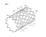
拡大された後、そのステントの硬質セグメントは、好ましくは、1mmの長さの側をもつ細かいダイアモンド形状のメッシュを提供して、体管の直線状部分に連続的、かつ、均一な支持を提供する。
上記コネクターは、隣接セグメントを接続する複数又は多数の実質的にらせん状のリンクとして、履行されることができる。あるいは、コネクターは、各々少なくとも1のリンクをもつリンクとして履行されることができる。コネクターは、典型的には、体管の直線状及び曲線状部分に連続的、かつ、均一な支持を提供するために8〜24のリンクをもつ。After being expanded, the rigid segment of the stent preferably provides a fine diamond-shaped mesh with 1 mm long sides to provide continuous and uniform support to the straight portion of the body vessel To do.
The connector can be implemented as multiple or multiple substantially spiral links connecting adjacent segments. Alternatively, the connectors can be implemented as links each having at least one link. Connectors typically have 8 to 24 links to provide continuous and uniform support for the straight and curved portions of the body tube.
ステントは、脈管内デリバリーのために縮められた直径をもち、そして、体管の管腔を支持するために半径方向に外側に拡がる力を適用するために直径を拡大するように、それらのカテーテル・デリバリー・システムのバルーン形成部分の膨張により、その後変形される。ステントの縮められた直径及び拡大された直径は、典型的には、それぞれ、 1.0〜3.5mm と 3.5〜10.0mmの範囲内にある。 Stents have a reduced diameter for intravascular delivery, and their catheters expand in diameter to apply a radially outward force to support the lumen of the body vessel. • It is subsequently deformed by inflation of the balloon-forming part of the delivery system. The reduced diameter and expanded diameter of the stent are typically in the range of 1.0-3.5 mm and 3.5-10.0 mm, respectively.
ステントは、好ましくは、弾性の生体適合性材料よりも低い記憶の、より可塑性の、例えば、ステンレス・スチール 316L、金、タンタル、等から作られる。これは、それらが、それらの縮められた直径からそれらの拡大された直径に塑性的に変形されることを可能にする。
ヒトの冠状動脈内移植のための典型的なステントは、そのステントの両端が、曲げられたとき約9mmの曲線半径において45°〜135 °の間の角度を定める(subtend) 、2〜6の1mm長のコネクターにより接続された3〜7の 2.2mm長のステント・セグメントを含む、9〜21mmの長さである。The stent is preferably made from a lower memory, more plastic, eg, stainless steel 316L, gold, tantalum, etc., less than an elastic biocompatible material. This allows them to be plastically deformed from their shrunken diameter to their enlarged diameter.
A typical stent for human intracoronary implantation has an angle between 45 ° and 135 ° with a curved radius of about 9 mm when bent at both ends of the stent, between 2 and 6 9-21 mm long, including 3-7 2.2 mm long stent segments connected by a 1 mm long connector.
好ましい態様の説明
本発明は、曲った体管、例えば、生きた動物又はヒトの末梢又は冠状動脈を通してのデリバリー及び開通性を維持するためのバルーン血管形成手術の一部としてのその内の移植のための関節のあるステントに関する。DESCRIPTION OF PREFERRED EMBODIMENTS The present invention relates to the delivery of bent body vessels, such as living animals or humans, through the peripheral or coronary arteries, and the implantation therein as part of balloon angioplasty to maintain patency. The present invention relates to an articulated stent.
本発明の関節のあるステントの原理と操作は、図面とこれに関する説明を参照することにより、よりよく理解されることができる。
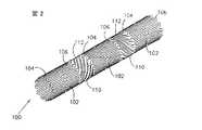
これから図面を参照するが、図2〜4は、本発明の教示に従って構築され、そして作用する、一般的に設計された関節のあるステント(100) であって、コネクター(110) により接続された多数の実質的に硬質のセグメント(102) を一般に含むステントを示す。The principles and operation of the articulated stent of the present invention can be better understood with reference to the drawings and the associated description.
Referring now to the drawings, FIGS. 2-4 are generally designed articulated stents (100) constructed and operative in accordance with the teachings of the present invention, connected by connectors (110). Fig. 2 shows a stent generally including a number of substantially rigid segments (102).
セグメント(102) は、好ましくは、図4中に最良に示すように拡大時に1mm側をもつ互いに接続されたダイアモンド形状のセル(108) の細かいダイアモンド・メッシュを提供するように作られる。ステント(100) の意図された直径に依存して、セグメント(102) は、典型的には、8〜24の間のダイアモンド形状のセル(108) を含む。 The segment (102) is preferably made to provide a fine diamond mesh of interconnected diamond shaped cells (108) having 1 mm sides when expanded as best shown in FIG. Depending on the intended diameter of the stent (100), the segment (102) typically includes between 8 and 24 diamond shaped cells (108).
コネクター(110) は、隣接セグメント(102) の前端(104) と後端(106) を接続するリンク(112) を含む。リンク(112) は、好ましくは、リンク(112) の数がセル(108) の数に等しくなるように、隣接セグメント(102) の前端(104) と後端(106) において、ダイアモンド形状のセル(108) の頂点の間に実質的にらせん状に延びる。リンク(112) は、好ましくは、コネクター(110) がいずれの方向にも等しく曲げられることができるように、そして体管の直線状部分と曲線状部分の両方に連続的、かつ、均一な支持を提供するように、セグメント(102) の周辺に均一に展開される。 The connector (110) includes a link (112) connecting the front end (104) and the rear end (106) of the adjacent segment (102). The links (112) are preferably diamond-shaped cells at the front end (104) and rear end (106) of the adjacent segment (102) so that the number of links (112) is equal to the number of cells (108). Extends substantially spirally between the vertices of (108). The link (112) preferably provides continuous and uniform support so that the connector (110) can be bent equally in either direction and on both the straight and curved parts of the body tube. So that it is evenly deployed around the segment (102).
セグメント(102) の、それぞれ、前端(104) と後端(106) における他のコネクター(110) は、時計廻りと反時計廻り方向において巻かれたリンク(112) をもつ。あるいは、巻きコネクター(110) は、血管壁に対するリンク(112) と隣接セグメント(102) の回転変位、そしてより重要には、そのデリバリー・システムのバルーンが、ステント(100) が拡大されるときに、最小化されることを保証する。 The other connectors (110) at the front end (104) and rear end (106), respectively, of the segment (102) have links (112) wound in the clockwise and counterclockwise directions. Alternatively, the wrap connector (110) can be used for rotational displacement of the link (112) and adjacent segment (102) relative to the vessel wall and, more importantly, the balloon of the delivery system when the stent (100) is expanded. To ensure that it is minimized.
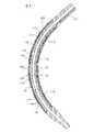
本発明の特徴は、コネクター(110) が、図2中に最良に示すようにステント(100) に力が加えられないとき一般に筒状の形状をもち、そして図3に最良に示すようにステント(100) が曲げられたとき、差異をもって延ばされ、そして縮められた曲った形状をもつということである。曲げられた形状は、リンク(112) の2つの相対的に相対する変位によりひき起こされる。第1に、コネクター(110) の差異的な延びが、互いに離れるように配置されているリンク(112) により(114) で表されたその凸状部分において生じる。第2に、コネクター(110) の差異的な縮みが、互いに向うように配置されたリンク(112) により(116) で表されたその凹状部分において生じる。 A feature of the present invention is that the connector (110) has a generally cylindrical shape when no force is applied to the stent (100) as best shown in FIG. 2, and as best shown in FIG. When (100) is bent, it has a bent shape that is extended and contracted with a difference. The bent shape is caused by two relatively opposite displacements of the link (112). First, the differential extension of the connector (110) occurs at its convex portion, represented by (114), by links (112) that are arranged away from each other. Secondly, a differential shrinkage of the connector (110) occurs in its concave portion, represented by (116), by links (112) arranged to face each other.
ステント(100) は、図2と3中に示すような曲った体管を通してのデリバリーのための縮まった直径及び体管を支持するための図4に示すような拡大された直径をもつ。ステント(100) は、好ましくは、弾性の、生体適合性材料よりも低い記憶、より可塑性の、例えば、ステンレス・スチール 316L、金、タンタル等であって、その縮まった直径からその拡大された直径に、それが、塑性的に変形することを可能にするものから作られる。ステント(100) の縮まった直径と拡大された直径は、典型的には、それぞれ、 1.0〜3.5mm の、そして 3.5〜10.0mmの範囲内にある。 The stent (100) has a reduced diameter for delivery through a curved body tube as shown in FIGS. 2 and 3 and an expanded diameter as shown in FIG. 4 for supporting the body tube. The stent (100) is preferably made of a lower memory, more plastic, eg, stainless steel 316L, gold, tantalum, etc., elastic, biocompatible material, from its reduced diameter to its expanded diameter It is made from what allows it to deform plastically. The reduced and expanded diameters of the stent (100) are typically in the range of 1.0 to 3.5 mm and 3.5 to 10.0 mm, respectively.
図5〜7を見ると、ステント(100) は、そのカテーテル・デリバリー・システム(120) の一部を形成するバルーン(118) を重層するように示されている。ステント(100) は、体管の壁を支持するための図7中に示すその拡大された直径へのバルーン(118) の膨張を通しての塑性変形のための図6中に示すその縮まった直径の状態において、そのカテーテル・デリバリー・システム(120) 上に載せられている。ヒト冠状動脈内への移植のための例示的なステントは、典型的には、4つの1mm長コネクター(110) により接続された5つの 2.2mm長セグメント(102) から作られた15mm長をもち、そしてその両端が約9mmの曲率半径において90°の角度を定めるように曲がることができる。 5-7, the stent (100) is shown overlaid with a balloon (118) that forms part of its catheter delivery system (120). The stent (100) has its reduced diameter shown in FIG. 6 for plastic deformation through inflation of the balloon (118) to its enlarged diameter shown in FIG. 7 to support the body vessel wall. In state, it is mounted on the catheter delivery system (120). An exemplary stent for implantation into a human coronary artery typically has a 15 mm length made from five 2.2 mm long segments (102) connected by four 1 mm long connectors (110). , And its ends can be bent to define a 90 ° angle at a radius of curvature of about 9 mm.
関節のあるステント(100) のデリバリーは、従来技術の関節のあるステント (10) のデリバリーよりもかなり簡単である。なぜなら、ステント(100) は、いずれの方向においても等しく曲がることができ、そしてそれ故、異常に曲った部分を通過するために専用の(dedicated) 角度配向を要求しない。この利点は、複数又は多数の曲った部分をもつ血管を通してのデリバリーにとって特に重要である。従来技術のステント (10) を超えるステント(100) のさらなる利点は、ステント(100) が、コネクター部分(114) と(116) が、それぞれ、その凸に曲った部分と凹に曲った部分を支持しながら、その直線状部分を支持するセグメント(102) と力の加えられていないコネクター(110) により血管の長さ全体に沿って連続的、かつ、均一な支持を提供するということである。 Delivery of the articulated stent (100) is much simpler than that of the prior art articulated stent (10). Because the stent (100) can be bent equally in either direction, and therefore does not require a dedicated angular orientation to pass through an abnormally bent portion. This advantage is particularly important for delivery through blood vessels with multiple or multiple bends. A further advantage of the stent (100) over the prior art stent (10) is that the stent (100) has a connector portion (114) and (116), respectively, with its convex and concave portions. This means that while supporting, the segment (102) supporting the linear part and the unforced connector (110) provide continuous and uniform support along the entire length of the vessel .
図8と9を参照すると、関節のあるステント(122) であって、コネクター(124) が、1以上のよじれ(kinks) (128) をもつリンク(126) を含むものを示している。コネクター(124) のデザインは、コネクター(110) のデザインよりも優先される。なぜなら、2つの理由のためにステント(100) はバルーン(118) を破裂させる傾向をもつからである。第1に、バルーン(118) の凸状部分に重層するリンク(112) は、ステント(100) が曲げられたとき内側に片寄る傾向をもつ。第2に、セグメント(102) は、ステント(100) が拡大されるとき、バルーン(118) に対して回転変位を示す。 Referring to FIGS. 8 and 9, an articulated stent (122) is shown in which the connector (124) includes a link (126) having one or more kinks (128). The design of the connector (124) takes precedence over the design of the connector (110). This is because the stent (100) tends to rupture the balloon (118) for two reasons. First, the link (112) overlying the convex portion of the balloon (118) tends to deflect inward when the stent (100) is bent. Second, segment (102) exhibits rotational displacement relative to balloon (118) when stent (100) is expanded.
この場合、コネクター(124) の差異をもって延び、そして縮んだ曲った形状は、先に述べたように、リンク(112) の2つの相対的に逆の変位により生じる。但し、凸部分(114) におけるコネクター(124) の差異のある延びは、いくぶんまっすぐなよじれ(128) により生じ、一方、凹状部分(116) におけるコネクター(124) の差異のある縮みは、よりきつく曲ったよじれ(128) により生じる。 In this case, the curved shape that extends and contracts with the difference of the connector (124) is caused by two relatively opposite displacements of the link (112), as described above. However, the differential extension of the connector (124) at the convex portion (114) is caused by a somewhat straight kinking (128), while the differential shrinkage of the connector (124) at the concave portion (116) is more tight. Caused by bent kinks (128).
ステント(100) に類似のやり方で、ステント(122) は、図8と9中に示すような曲った体管を通してのデリバリーのための縮んだ直径とその内に移植されたとき体管を支持するための図10中に示す拡大した直径をもつ。
本発明を限定された数の態様について説明してきたけれども、本発明の多くの変更、修正及び他の応用が可能であることが理解されるであろう。In a manner similar to the stent (100), the stent (122) supports the body tube when implanted therein with a reduced diameter for delivery through a curved body tube as shown in FIGS. The enlarged diameter shown in FIG.
Although the present invention has been described with respect to a limited number of embodiments, it will be understood that many variations, modifications and other applications of the present invention are possible.
本発明を、添付図面を参照して、例示としてのみ、以下に説明する。 The invention will now be described, by way of example only, with reference to the accompanying drawings.
Claims (9)
Translated fromJapanesea)長さ方向の孔を定める複数又は多数の実質的に筒状、かつ、実質的に硬質のセグメント、ここで、上記硬質セグメントの各々は複数の頂部(apexes)が提供される、及び
b)上記硬質セグメントを接続する複数又は多数の曲がることのできる接続リンクであって、第1端を有する第1部分と第2端を有する第2部分をもち、その各々が横方向から見たとき、上記部分の間に置かれた屈曲領域をもつリンク、
を含み、ここで、上記各曲がることのできるリンクの第1端と第2端は、隣接硬質セグメントの実質的に長さ方向に整列するように接続され、それにより、上記ステントが半径方向に拡大されるとき、上記曲がることのできるリンクが、上記硬質セグメントが短縮する傾向を実質的に補償するよう長さ方向に延び、かつ、上記セグメントが互いに対して回転する傾向をもたない、前記ステント。An articulated stent that can be expanded with a longitudinal axis:
a) a plurality or a plurality of substantially cylindrical and substantially rigid segments defining longitudinal holes,wherein each of said rigid segments is provided with a plurality of apexes; and b ) A plurality of or a plurality of bending connecting links connecting the rigid segments, eachhaving a first portionhaving a first end and a second portionhaving a second end , each viewed from the side. A link with a bend area placed between the parts,
Only including, where the first and second ends of the links which can bend each are connected so as to be aligned in a substantially longitudinal direction of the adjacent rigid segments, whereby the stent is radially The bendable link extends lengthwise to substantially compensate for the tendency of the rigid segments to shorten, and the segments do not tend to rotate relative to each other. The stent.
Priority Applications (1)
| Application Number | Priority Date | Filing Date | Title |
|---|---|---|---|
| JP2004363421AJP4015659B2 (en) | 2004-12-15 | 2004-12-15 | Articulated stent |
Applications Claiming Priority (1)
| Application Number | Priority Date | Filing Date | Title |
|---|---|---|---|
| JP2004363421AJP4015659B2 (en) | 2004-12-15 | 2004-12-15 | Articulated stent |
Related Parent Applications (1)
| Application Number | Title | Priority Date | Filing Date |
|---|---|---|---|
| JP2001002642ADivisionJP2001224696A (en) | 2001-01-10 | 2001-01-10 | Stent having joint |
Publications (2)
| Publication Number | Publication Date |
|---|---|
| JP2005161067A JP2005161067A (en) | 2005-06-23 |
| JP4015659B2true JP4015659B2 (en) | 2007-11-28 |
Family
ID=34737429
Family Applications (1)
| Application Number | Title | Priority Date | Filing Date |
|---|---|---|---|
| JP2004363421AExpired - LifetimeJP4015659B2 (en) | 2004-12-15 | 2004-12-15 | Articulated stent |
Country Status (1)
| Country | Link |
|---|---|
| JP (1) | JP4015659B2 (en) |
Cited By (2)
| Publication number | Priority date | Publication date | Assignee | Title |
|---|---|---|---|---|
| JP2015009143A (en)* | 2014-01-27 | 2015-01-19 | 株式会社World Medish | Highly-flexible stent |
| JP2015008931A (en)* | 2013-06-28 | 2015-01-19 | 株式会社World Medish | Highly-flexible stent |
Families Citing this family (1)
| Publication number | Priority date | Publication date | Assignee | Title |
|---|---|---|---|---|
| KR101550341B1 (en) | 2013-10-16 | 2015-09-07 | 주식회사 바이오알파 | Stent |
- 2004
- 2004-12-15JPJP2004363421Apatent/JP4015659B2/ennot_activeExpired - Lifetime
Cited By (2)
| Publication number | Priority date | Publication date | Assignee | Title |
|---|---|---|---|---|
| JP2015008931A (en)* | 2013-06-28 | 2015-01-19 | 株式会社World Medish | Highly-flexible stent |
| JP2015009143A (en)* | 2014-01-27 | 2015-01-19 | 株式会社World Medish | Highly-flexible stent |
Also Published As
| Publication number | Publication date |
|---|---|
| JP2005161067A (en) | 2005-06-23 |
Similar Documents
| Publication | Publication Date | Title |
|---|---|---|
| US6059811A (en) | Articulated stent | |
| CA2219488C (en) | Articulated stent | |
| US6962603B1 (en) | Longitudinally flexible expandable stent | |
| CN101484089B (en) | Flexible stent | |
| US6270524B1 (en) | Flexible, radially expansible luminal prostheses | |
| JP4029116B2 (en) | Flat wire stent | |
| JP5638552B2 (en) | Flexlink optimized for expandable stents | |
| US6818014B2 (en) | Longitudinally flexible expandable stent | |
| JP5259746B2 (en) | Lumen prosthesis | |
| US6607554B2 (en) | Universal stent link design | |
| US20060190072A1 (en) | Flexible cells for axially interconnecting stent components | |
| JP4015659B2 (en) | Articulated stent | |
| KR101015329B1 (en) | Surgical stent | |
| AU754584B2 (en) | Articulated stent | |
| JP5037514B2 (en) | Stent with untwisted shape | |
| JP2001224696A (en) | Stent having joint | |
| EP1669043A2 (en) | Articulated stent | |
| IL157020A (en) | Articulated stent | |
| MXPA97008231A (en) | Articula implants | |
| IL157019A (en) | Articulated stent | |
| HK1038175B (en) | Articulated stent |
Legal Events
| Date | Code | Title | Description |
|---|---|---|---|
| A131 | Notification of reasons for refusal | Free format text:JAPANESE INTERMEDIATE CODE: A131 Effective date:20060516 | |
| A521 | Written amendment | Free format text:JAPANESE INTERMEDIATE CODE: A523 Effective date:20060727 | |
| A02 | Decision of refusal | Free format text:JAPANESE INTERMEDIATE CODE: A02 Effective date:20060919 | |
| A521 | Written amendment | Free format text:JAPANESE INTERMEDIATE CODE: A523 Effective date:20070117 | |
| A521 | Written amendment | Free format text:JAPANESE INTERMEDIATE CODE: A821 Effective date:20061221 | |
| A911 | Transfer of reconsideration by examiner before appeal (zenchi) | Free format text:JAPANESE INTERMEDIATE CODE: A911 Effective date:20070207 | |
| TRDD | Decision of grant or rejection written | ||
| A01 | Written decision to grant a patent or to grant a registration (utility model) | Free format text:JAPANESE INTERMEDIATE CODE: A01 Effective date:20070814 | |
| A61 | First payment of annual fees (during grant procedure) | Free format text:JAPANESE INTERMEDIATE CODE: A61 Effective date:20070913 | |
| FPAY | Renewal fee payment (event date is renewal date of database) | Free format text:PAYMENT UNTIL: 20100921 Year of fee payment:3 | |
| R150 | Certificate of patent or registration of utility model | Free format text:JAPANESE INTERMEDIATE CODE: R150 | |
| FPAY | Renewal fee payment (event date is renewal date of database) | Free format text:PAYMENT UNTIL: 20100921 Year of fee payment:3 | |
| RD04 | Notification of resignation of power of attorney | Free format text:JAPANESE INTERMEDIATE CODE: R3D04 | |
| FPAY | Renewal fee payment (event date is renewal date of database) | Free format text:PAYMENT UNTIL: 20110921 Year of fee payment:4 | |
| FPAY | Renewal fee payment (event date is renewal date of database) | Free format text:PAYMENT UNTIL: 20110921 Year of fee payment:4 | |
| FPAY | Renewal fee payment (event date is renewal date of database) | Free format text:PAYMENT UNTIL: 20120921 Year of fee payment:5 | |
| FPAY | Renewal fee payment (event date is renewal date of database) | Free format text:PAYMENT UNTIL: 20130921 Year of fee payment:6 | |
| R250 | Receipt of annual fees | Free format text:JAPANESE INTERMEDIATE CODE: R250 | |
| R250 | Receipt of annual fees | Free format text:JAPANESE INTERMEDIATE CODE: R250 | |
| EXPY | Cancellation because of completion of term |