JP4015303B2 - Vehicle air conditioner with cold storage unit - Google Patents
Vehicle air conditioner with cold storage unitDownload PDFInfo
- Publication number
- JP4015303B2 JP4015303B2JP30448598AJP30448598AJP4015303B2JP 4015303 B2JP4015303 B2JP 4015303B2JP 30448598 AJP30448598 AJP 30448598AJP 30448598 AJP30448598 AJP 30448598AJP 4015303 B2JP4015303 B2JP 4015303B2
- Authority
- JP
- Japan
- Prior art keywords
- cooling
- cold storage
- storage unit
- refrigerant
- heating
- Prior art date
- Legal status (The legal status is an assumption and is not a legal conclusion. Google has not performed a legal analysis and makes no representation as to the accuracy of the status listed.)
- Expired - Lifetime
Links
- 238000001816coolingMethods0.000claimsdescription115
- 239000003507refrigerantSubstances0.000claimsdescription81
- 238000010438heat treatmentMethods0.000claimsdescription73
- 238000004378air conditioningMethods0.000claimsdescription32
- 239000007788liquidSubstances0.000claimsdescription18
- 238000007791dehumidificationMethods0.000claims1
- XLYOFNOQVPJJNP-UHFFFAOYSA-NwaterSubstancesOXLYOFNOQVPJJNP-UHFFFAOYSA-N0.000description22
- 239000000498cooling waterSubstances0.000description19
- 238000010586diagramMethods0.000description7
- 230000002265preventionEffects0.000description6
- 239000011232storage materialSubstances0.000description6
- 239000002826coolantSubstances0.000description3
- 238000005057refrigerationMethods0.000description3
- 230000007423decreaseEffects0.000description2
- 230000006866deteriorationEffects0.000description2
- 239000011491glass woolSubstances0.000description2
- 239000011810insulating materialSubstances0.000description2
- 239000000463materialSubstances0.000description2
- 230000001172regenerating effectEffects0.000description2
- 230000033228biological regulationEffects0.000description1
- 238000007664blowingMethods0.000description1
- 239000003990capacitorSubstances0.000description1
- 230000005494condensationEffects0.000description1
- 238000009833condensationMethods0.000description1
- 230000001143conditioned effectEffects0.000description1
- 230000000694effectsEffects0.000description1
- 230000007613environmental effectEffects0.000description1
- 238000000926separation methodMethods0.000description1
- 238000010257thawingMethods0.000description1
- 238000011144upstream manufacturingMethods0.000description1
Images


Landscapes
- Air-Conditioning For Vehicles (AREA)
- Air Conditioning Control Device (AREA)
Description
Translated fromJapanese【0001】
【発明の属する技術分野】
本発明は、バス等の車両に設置され、車室内における冷房を行う車両用空気調和装置に係り、特に、蓄冷ユニットを備えた車両用空気調和装置に関するものである。
【0002】
【従来の技術】
バス等の車室内を空気調和することにより、乗員・乗客に快適な車室内環境を提供することができる車両用空気調和装置は、冷房運転及び暖房運転を行うことができる。
冷房運転では、エバポレータを通過することで冷媒と熱交換して冷却・除湿された空調空気が、ブロアの作動によって車室内に設置された冷房ダクト内を送風され、冷房ダクトに設けられた各吹出口から車室内へ向けて吹き出される。このエバポレータに低温低圧の液冷媒を供給する冷媒系は、低温低圧のガス冷媒を圧縮機で圧縮して高温高圧のガス冷媒とし、このガス冷媒をコンデンサへ送って外気で冷却する。コンデンサで凝縮された冷媒はレシーバで気液分離させられ、液冷媒がレシーバから膨張弁に送られて減圧膨張することで低温低圧の液冷媒となり、再度エバポレータへ供給される冷凍サイクルを構成している。
暖房運転では、加熱源としてエンジン冷却水がヒータコアに導入され、このヒータコアを通過して温められた空気が、ブロアの作動によって車室内に設置された暖房ダクト内を送風され、暖房ダクトに設けられた各吹出口から車室内へ向けて吹き出される。なお、路線バスなどでは、車室内の適所に設置した複数の放熱器を結んでエンジン冷却水を直接循環させる方式を採用したものもある。
【0003】
バスに装備されている空気調和装置には、主として大型の観光バスに採用されているサブエンジン方式と、主として路線バスや小型バスなどに採用されている直結方式とがある。
サブエンジン方式は、車両の走行用エンジン(メインエンジン)とは別に空気調和装置専用のエンジン(サブエンジン)を備えたものであり、このサブエンジンの駆動力を利用して冷媒系の圧縮機などを運転するように構成されている。このサブエンジン方式の場合、サブエンジンや圧縮機等の主要機器がユニット化され、通常車体中央部の車室下側のスペースに設置されている。
一方、直結方式の車両用空気調和装置は、乗用車等と同様に車両の走行用エンジンから冷媒系の圧縮機などに駆動力を得るものである。路線バスの場合には、圧縮機は車体後部のエンジン近傍に設置され、エバポレータやコンデンサは車体の屋根上に設置されることが多い。また、小型バスの場合には、圧縮機は車体前部のエンジン近傍に設置され、コンデンサは車体中央部の車室下側に、そしてエバポレータは車体後部の車室上部(天井)に設置されることが多い。
なお、バスの場合は通常、冷房用のダクト(冷房ダクト)が車室内の左右天井付近に配設され、暖房用のダクト(暖房ダクト)が車室内の左右床面付近に配設されている。
【0004】
さて、近年の環境問題に対応するため、駐車場等ではエンジンのアイドリングを停止することが望まれている。特に、観光地の駐車場等では、自然環境を保護する観点からアイドリングストップ規制が実施されているところもある。
このため、たとえば観光バスの空気調和装置は、サブエンジン方式及び直結方式のいずれであっても、夏期の駐車場で乗客を待つ間に運転することができず、したがって車室内の温度が上昇してしまうという問題がある。このような問題に対処するため、冷房運転時の余剰な冷凍能力を活用して冷熱を蓄積することができるようにした、蓄冷システムが開発されている。この蓄冷システムは、蓄冷材を充填した蓄冷パネルを所定の間隔で並列に並べ、その外側をグラスウール等の断熱材で囲んだ蓄冷ユニットに冷媒系から冷媒を導入するように構成されたものであり、上述した空気調和装置の停止時には蓄冷材に蓄冷した冷熱を放冷することで車室内の温度上昇を抑制することができる。
【0005】
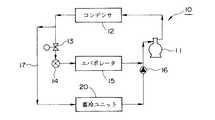
図7は、上述した蓄冷ユニットを備えた冷媒系を簡単に示したものである。図中の符号10は冷媒系、11は圧縮機、12はコンデンサ、13は冷房・蓄冷切換電磁弁、14は膨張弁、15はエバポレータ、16は逆流防止電磁弁、20は蓄冷ユニットである。
蓄冷ユニット20は、コンデンサ12と膨張弁14との間で分岐され、エバポレータ15と圧縮機11との間に合流する冷媒バイパス流路17に設置されている。図示の冷媒系10では、矢印で示すように冷媒は反時計廻りに循環し、冷房・蓄冷切換電磁弁13の開閉操作によって、冷媒が膨張弁14及びエバポレータ15を通る冷房運転時と、冷媒が膨張弁14及びエバポレータ15をバイパスして蓄冷ユニット20を通る蓄冷運転時とが切り換えられる。
【0006】
この結果、通常の冷房運転時には冷房・蓄冷切換電磁弁13を全開とし、エバポレータ15に供給される冷媒で通過する空気を冷房・除湿することができる。また、車室内が所望の温度まで下がって冷凍能力に余力が生じた場合には、冷房・蓄冷切換電磁弁13を全閉とする。これにより、冷媒は蓄冷ユニット20を通って蓄冷材を冷却するので、蓄冷材には冷熱が蓄積される。なお、逆流防止電磁弁16は、蓄冷運転から冷房運転に切り換えた時、冷媒が蓄冷ユニット20へ向けて逆流するのを防止する目的で設けられており、したがって、蓄冷運転時に全開となり、冷房運転時には全閉となる。
【0007】
【発明が解決しようとする課題】
ところで、上述した従来のサブエンジン方式の場合、たとえば春から夏又は夏から秋へ移る中間期のように空調負荷が低い時期には、車室内の設定温度を維持するために、ヒシテリシスが設けられているなどの理由から冷房運転と暖房運転とが交互に実施されるような状況になることがある。このような場合、冷房運転ではサブエンジンを運転する必要があり、サブエンジンの駆動力を利用した圧縮機の運転により冷媒が冷媒系を循環する。そして、電動のブロアにより吸引された空気がエバポレータを通過して冷却・除湿され、冷風となって車室内へ送風される。
【0008】
一方、暖房運転ではサブエンジンの駆動力は必要なく、電動のブロアにより吸引された空気がヒータコアを通過して温風となり、車室内へ送風される。すなわち、サブエンジン方式の場合でも、ヒータコアへ供給される加熱源の温水は走行用のメインエンジン冷却水が利用されるため、サブエンジンの運転は必要がないのである。
【0009】
上述したように、空調負荷が低い中間期には冷房運転が断続的に実施されるため、その都度サブエンジンを始動して運転を開始し、比較的短時間の運転を実施した後停止するということが頻繁に繰り返される。このため、サブエンジンを始動・停止させるたびに振動や騒音が頻繁に生じることになり、車室内への影響を完全に遮断するのは困難であることから、快適な乗り心地や良好な車室内環境を提供して商品性を向上させるため何らかの対策が望まれていた。
【0010】
そこで本発明は、空調負荷が低い中間期におけるサブエンジンの始動・停止回数を低減させて、振動や騒音によるフィーリングの悪化を改善することを課題としている。
【0011】
【課題を解決するための手段】
上記課題を解決するために本発明においては以下の手段を採用した。
請求項1に記載の蓄冷ユニットを備えた車両用空気調和装置は、低温低圧のガス冷媒を圧縮する圧縮機と、該圧縮機から供給された高温高圧のガス冷媒を外気で冷却するコンデンサと、該コンデンサで凝縮された冷媒を気液分離させるレシーバと、該レシーバから送られてきた液冷媒を減圧膨張させる膨張弁と、該膨張弁から低温低圧の液冷媒を受け車室内の空気と熱交換して冷却及び除湿するエバポレータとを具備してなる冷媒系が、前記膨張弁及び前記エバポレータをバイパスして接続された蓄冷ユニットを備え、空調負荷が低く冷房運転及び暖房運転が交互に繰り返される中間期には、前記蓄冷ユニットに冷媒を供給する蓄冷運転を一時的に実施して冷房運転時の冷房能力を抑制し、かつ、前記蓄冷ユニットからの放冷運転を実施して暖房運転時の暖房能力を抑制したことを特徴とするものである。
【0012】
このような蓄冷ユニットを備えた車両用空気調和装置によれば、蓄冷ユニットを利用することで冷房運転及び暖房運転の能力が抑制されるので、冷房運転と暖房運転との運転切換え回数が低減され、従って、サブエンジンの始動・停止の回数を減らすことができる。
【0013】
請求項2に記載の蓄冷ユニットを備えた車両用空気調和装置によれば、前記冷房能力の抑制時には、前記エバポレータと前記蓄冷ユニットとに冷媒が交互に供給されることを特徴としている。
【0014】
このような蓄冷ユニットを備えた車両用空気調和装置によれば、冷媒の供給先がエバポレータと蓄冷ユニットとで交互に切換えられるので、冷媒が蓄冷ユニットで冷熱を蓄えるのに利用される時間帯の分だけエバポレータで空気を冷却・除湿するのに利用される時間帯が減り、結果的に冷房運転の能力が抑制される。
【0015】
請求項3に記載の蓄冷ユニットを備えた車両用空気調和装置は、前記暖房能力の抑制時には、暖房運転と放冷運転とが交互に実施されることを特徴とするものである。
【0016】
このような蓄冷ユニットを備えた車両用空気調和装置によれば、暖房運転と放冷運転とが交互に切換えられるので、暖房運転による温風と放冷運転による冷風とがサブエンジンを運転することなく交互に供給されるので、結果的に暖房運転の能力が抑制される
【0017】
請求項4に記載の蓄冷ユニットを備えた車両用空気調和装置は、前記暖房能力の抑制時には、暖房運転と放冷運転とが同時に実施されることを特徴とするものである。
【0018】
このような蓄冷ユニットを備えた車両用空気調和装置によれば、暖房運転による温風と放冷運転による冷風とが混合されるので、結果的に暖房運転の能力が抑制される。
【0019】
【発明の実施の形態】
以下、本発明の実施の形態を図面に基づいて説明する。
図1ないし図3は、大型観光バスに設置されたサブエンジン方式の車両用空気調和装置が蓄冷ユニットを備えた例を示している。
【0020】
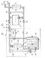
図1は観光バスの概要を示す斜視図で、車体中央部の車室下側に空調ユニット1が設置され、該空調ユニット1に接続された空調ダクト5は、左右に分岐した後さらに、それぞれ冷暖切換ダンパ格納部6,6で車室上部へ向かう冷房ダクト7、7と車室床面へ向かう暖房ダクト9、9とに分岐される。この空調ユニット1は、サブエンジンで駆動される圧縮機などの冷媒系やヒータコアなどがユニット化されたものである。この空調ユニット1は、同様に車体中央部下側に隣接して設置された蓄冷ユニット20と冷媒配管2,3及び連結ダクト4により接続されている。
【0021】
図2は、空調ユニット1及び蓄冷ユニット20を車体側面から見た正面図で、図中の符号1はサブエンジン方式の空調ユニット、1aは電動モータで駆動される送風用のブロア、4は車室内空気の導入ダクト4aと蓄冷風導入ダクト4bとが合流する連結ダクト、8a,8bは冷房・蓄冷切換ダンパである。
【0022】
図3は蓄冷ユニット20を備えた冷媒系10の構成を示す系統図で、通常の冷房運転時には、サブエンジン11aを駆動源として圧縮機11が運転され、低温低圧のガス冷媒を圧縮する。こうして高温高圧となったガス冷媒は、コンデンサ12へ送られて外気と熱交換する。この結果、高温高圧のガス冷媒は冷却されて凝縮し、さらにレシーバ18へ送られて気液の分離がなされ、高温高圧の液冷媒がドライヤ19を経て膨張弁14へ導かれる。膨張弁14において減圧膨張した高温高圧の液冷媒は、低温低圧の液冷媒となってエバポレータ15へ供給され、ブロア1aに吸引されてエバポレータ15を通過する空気と熱交換して冷却及び除湿する。この熱交換により低温低圧のガス冷媒となった冷媒は、圧縮機11に戻って再度圧縮され、以下このような時計廻りの循環を繰り返して冷凍サイクルが構成される。
【0023】
通常の冷房運転時は、ブロア1aの作動によって車室内の空気が吸引され、導入ダクト4a及び連結ダクト4を通って空調ユニット1に導かれる。この時、冷房・蓄冷切換ダンパ8a,8bは共に、導入した車室内の空気が蓄冷ユニット20を通過しないよう入口及び出口を閉じている。そして、空調ユニット1においてエバポレータを通過して空調された導入空気は、空調ダクト5により冷暖切換ダンパ格納部6に導かれ、ここの冷暖切換ダンパが暖房ダクト側を閉じていることから、冷房ダクト7に流れて各吹出口から車室内へ流出する。
【0024】
一方、ドライヤ19と膨張弁14との間には、高温高圧の液冷媒を蓄冷ユニット20へ導くための冷媒配管(以下、バイパス冷媒往路と呼ぶ)2が分岐して設けられ、該分岐部の膨張弁14側には、通常の冷房運転時と後述する蓄冷運転時とで冷媒流路を切り換える冷房・蓄冷切換電磁弁13が設けられている。蓄冷ユニット20は、蓄冷材を充填した複数の蓄冷パネル21を所定の間隔で並べたもので、図示の場合3枚の蓄冷パネル21を1ユニットとして冷媒入口に蓄冷用電磁弁22をそれぞれ設け、4ユニットで合計12枚の蓄冷パネルが並列に並べられている。そして、各蓄冷パネル21の冷媒入口には蓄冷用電磁弁22の後流側にそれぞれ膨張弁23が設けられており、これら蓄冷パネル21、蓄冷用電磁弁22、膨張弁23は、全体がグラスウールなどの断熱材24で囲まれている。なお、各蓄冷パネル21を通過して蓄冷材を冷却した冷媒は、冷媒配管(以下、バイパス冷媒復路と呼ぶ)3を通って圧縮機11の上流側に戻されるが、このバイパス復路3には、蓄冷運転から冷房運転に切り換えた時、冷媒が蓄冷ユニット20へ逆流するのを防止する目的で逆流防止電磁弁16が設けられている。
【0025】
そして、この蓄冷ユニット20は、通常の冷房運転に余剰が生じたとき、すなわち車室内が所定の空調温度まで十分に冷房された時などに、冷房・蓄冷切換電磁弁13を全開から全閉に切り換えると共に、蓄冷用電磁弁22及び逆流防止電磁弁16を全閉から全開に切り換えて、レシーバ18から供給されドライヤ19を通過した高温高圧の液冷媒を導入する。バイパス冷媒往路2を通って蓄冷ユニット20に導入された高温高圧の液冷媒は、膨張弁23で減圧膨張して低温低圧の液冷媒となり、蓄冷パネル21内を通過する際に蓄冷材を冷却するので、蓄冷材には冷熱が蓄積される。そして、車室内の温度が所定値より高くなるなどして通常の冷房運転が再度必要になれば、冷房・蓄冷切換電磁弁13を全閉から全開に切り換えると共に、蓄冷用電磁弁22及び逆流防止電磁弁16を全開から全閉に切り換えて、冷媒が膨張弁14及びエバポレータ15を通って流れるように冷媒流路を切り換える。
なお、上述した各電磁弁を開閉操作して実施される冷房運転と蓄冷運転との切り換えは、一般的には適所に配設した温度センサなどから入力されるデータに基づき、図示を省略した空気調和装置の制御部で処理される。
【0026】
次に、上述した蓄冷ユニット20の放冷運転について説明する。この放冷運転は、サブエンジン11aの運転ができないかあるいは運転したくない時で、しかも、車室内の温度上昇を防止、あるいは最小限に抑えたいような時などに実施される。蓄冷ユニット20の冷熱を放冷する時には、やはりブロア1aの作動によって車室内の空気を吸引するが、冷房・蓄冷切換ダンパ8a,8bは共に、導入した車室内の空気が蓄冷ユニット20を通過するよう開閉操作される。そして、車室内から吸引された空気は蓄冷ユニット20を通過して冷やされ、蓄冷風導入ダクト4b及び連結ダクト4に導かれて空調ユニット1に入る。この時、空調ユニット1のエバポレータへの冷媒の供給は停止されているので、蓄冷風は単にエバポレータを通過し、以下通常の冷房運転時と同様に空調ダクト5により冷暖切換ダンパ格納部6に導かれ、さらに、冷房ダクト7に流れて各吹出口から車室内へ流出する。
【0027】
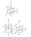
続いて、上述した空調ユニット1に熱源となるメインエンジン冷却水(温水)を供給する温水回路を図4に示して簡単に説明する。この温水回路30は、二点鎖線で囲まれた空調ユニット1に含まれる部分と、それ以外の部分、すなわち予め車両側に取り付けられている部分とが接続されたものである。なお、一点鎖線で囲んだフロントヒータ49は、通常オプションとして車両側に含まれる部分である。
図4において、符号のEは車両を走行させるメインエンジン、31はラジエータ、32は冷却水ポンプ、33はサーモバルブ、34はコンデンスタンクを示しており、冷却水ポンプ32の作動によってメインエンジン冷却水を循環させ、メインエンジンEの運転で発生した熱をラジエータ31から大気に放熱するようにしたメインエンジンEの冷却系を構成している。このようなメインエンジン冷却系は、メインエンジンEの出口及び入口から分岐した温水流路にそれぞれ設けられた温水止弁35,36を介して空気調和装置と接続されている。
【0028】
上述したメインエンジン冷却系から空気調和装置側へメインエンジン冷却水を供給するメインエンジン出口側の分岐流路には、温水止弁35の下流側にストレーナ37及び温水ポンプ38が設置され、この温水ポンプ38に加圧されたメインエンジン冷却水が空調ユニット1内の暖房系40に送られる。暖房系40は、予熱器41、温水制御弁42、ヒータコア43を主な構成要素としており、ヒータコア43を通って空気を加熱したメインエンジン冷却水は温水止弁36を通って再度メインエンジンEの冷却水系へ戻される。
このうち、温水制御弁42は、ヒータコア43へ導入するメインエンジン冷却水の流量を調節する機能を有するもので、この温水制御弁42による流量制御は、暖房の設定温度や車室内の実際の温度などの入力情報から図示省略の制御部が判断して定める弁開度の変更によって実施される。
【0029】
図5は、基本的には三方弁である温水制御弁42の開閉状態を示したもので、(a)はメインエンジン冷却水の全量がヒータコア43をバイパスするヒータコアバイパス流路44へ流れる状態(以下、バイパス位置と呼ぶ)、(b)はメインエンジン冷却水の全量が温水供給流路であるヒータコアメイン流路45を通ってヒータコア43へ導かれる状態(以下、メイン位置と呼ぶ)、(c)はメインエンジン冷却水がヒータコアバイパス流路44とヒータコアメイン流路45とに分割されて流れる状態(以下、中間位置と呼ぶ)である。このように、温水制御弁42は弁体42a,42bの作動によって弁開度状態が変化し、ヒータコア43を通過するメインエンジン冷却水の流量を0から100パーセントの間で調整することができる。
【0030】
メインエンジンEの冷却水系から導入したメインエンジン冷却水は、上述したヒータコア43へ導いて暖房運転に使用する他にも、たとえば冷房運転時に冷媒を導入して空気を冷却・除湿するエバポレータ15のデフロストヒータ46にも導かれる(図4参照)。このデフロストヒータ46は、エバポレータ15に付着した霜を除去する際にデフロスト電磁弁47を開き、メインエンジン冷却水を熱源として導入するものである。
また、このメインエンジン冷却水は、フロントヒータ電磁弁48を開くことにより、運転席周辺の暖房用として設けられているフロントヒータ49へも供給される。
なお、符号の50は、車体後部に設置されたメインエンジンEからヒータコア43までメインエンジン冷却水を導入する温水回路30の配管を示しており、車室内の左右床面に配設された暖房ダクト9(図1参照)内のいずれか一方を通って往復している。
【0031】
上述したように構成されている蓄冷ユニット20を備えた車両用空気調和装置は、空調負荷、すなわち冷房負荷又は暖房負荷が低い中間期において、以下に説明するような運転を実施する。
【0032】
たとえば春から夏へ季節が移り変わる時期には、車室内の温度が高く冷房運転を必要とする場合であっても、夏ほど大きな冷房負荷はない。このため、最も冷房能力が低い運転モードで冷房運転を実施しても、比較的短時間で設定温度まで下がってしまい、さらにヒステリシスの設定分だけ設定温度より低くなる。この間、サブエンジン11aは運転を続けて圧縮機11による冷媒の供給を行うが、サブエンジン11aが連続して運転される時間をできるだけ長くするためには、冷房能力をさらに抑制する必要がある。
【0033】
そこで、冷房運転を実施している間、冷媒の供給先をエバポレータ15と蓄冷ユニット20とに交互に切換えて運転する。すなわち、エバポレータ15に冷媒を供給する冷房運転と、蓄冷ユニット20に冷媒を供給する蓄冷運転とを交互に実施することで、サブエンジン11aを連続運転しても全体としての冷房能力を低下させることができる。この運転切換操作は、図示省略の制御部で冷房・蓄冷切換電磁弁13を開閉操作することによって行うことができる。この結果、サブエンジン11aが運転されて圧縮機11により供給される冷媒は、エバポレータ15に供給される時間帯だけ冷房運転の冷媒として機能し、蓄冷ユニット20に供給される時間帯は冷熱の蓄積に利用される。
なお、冷房運転と蓄冷運転とを交互に切換える運転時間の割合は、各種センサや設定温度などの条件から算出される演算値に応じて適宜変更すればよい。
【0034】
こうして冷房能力を低下させても、冷房負荷が小さいためやがて設定温度以下まで下がり、さらにヒステリシスの設定分だけ車室内の温度は下がった後、今度は暖房運転が実施される。この時点でサブエンジン11aは運転を停止するが、電動モータで駆動されるブロア1aによる送風は継続される。こうして開始された暖房運転も、その暖房負荷は大きなものではないので、できるだけ暖房能力を抑制して冷房運転が開始される温度に上昇するまで時間がかかるようにするのが好ましい。
【0035】
そこで、今度は最も暖房能力が低い運転モードの暖房運転と、蓄冷ユニット20からの放冷運転とを交互に実施する。すなわち、ヒータコア43にメインエンジン冷却水を供給する暖房運転と、蓄冷ユニット20から冷熱を放冷する放冷運転とを交互に実施することで、全体としての冷房能力を低下させるのである。この運転切換操作は図示省略の制御部で実施され、冷房・蓄冷切換ダンパ8a,8bの開閉操作、温水制御弁42の開度制御によって行うことができる。この結果、ブロア1aに吸引された空気は、メインエンジン冷却水がヒータコア43に供給されている時には温風となり、また、蓄冷ユニット20を通過する時には冷風となって車室内へ供給されるので、圧縮機11を運転しなくても、換言すればサブエンジン11aを運転しなくても、温風と冷風とを交互に吹き出すことができるので、全体としては暖房能力を下げることができる。
【0036】
ところで、暖房能力を下げるためには、上述したように暖房運転と放冷運転とを交互に実施するほかにも、暖房能力が低い運転モードの暖房運転と放冷運転とを同時に実施してもよい。この場合、蓄冷ユニット20を通過した冷風をヒータコア43で加熱することになるので、ブロア1aで吸引して蓄冷ユニット20を通過しない空気を加熱するのと比較して、加熱前の空気温度が低くなる。すなわち、ヒータコア43の暖房能力が同じであれば、初期温度が低い分だけ温風の温度も低くなるので、結果的に暖房能力が低下したことになる。
【0037】
図6は、空調負荷の低い中間期に冷房能力及び暖房能力を低下させた運転を実施できるようにした本発明の車両用空気調和装置の作用を説明するために示した図で、(a)は従来の装置の場合、(b)は本発明の装置の場合である。いずれの図も縦軸は冷房負荷、横軸は時間であって、最初は冷房運転の実施により時間の経過と共に冷房負荷が低下し、換言すれば、車室内温度が低下している。
【0038】
(a)の場合、時間ta1で冷房運転から暖房運転に切換えられてサブエンジンが停止する。そして、暖房運転の実施により車室内温度が上昇して冷房負荷が大きくなると、時間ta2で再度冷房運転が開始され、以後同様に時間ta3で冷房運転から暖房運転に、時間ta4で暖房運転から冷房運転にというように運転切換が実施されるので、その都度サブエンジン11aの運転停止及び運転開始が繰り返される。
なお、図中の傾斜が大きい程、冷房能力及び暖房能力が大きいことを示している。
【0039】
一方、(b)の場合は、冷房能力及び暖房能力を低下させたことにより傾斜が小さくなり、最初に冷房運転から暖房運転に切換えられる時間tb1は上述した時間ta1より長くなっている。また、最初に暖房運転から冷房運転に切換えられるまでの時間tb2−tb1も従来のta2−ta1より長くなっており、運転時間が同一であれば結果的に冷房運転と暖房運転との切換え回数、すなわちサブエンジン11aの始動及び停止の回数が少なくてすむことがわかる。
【0040】
なお、上述した図6(a),(b)は、縦軸を冷房負荷としているが、最初に暖房運転を実施する場合にはこの縦軸を暖房負荷とすればよい。
【0041】
【発明の効果】
上述した本発明の蓄冷ユニットを備えた車両用空気調和装置によれば、空調負荷の低い中間期において、蓄冷ユニットを有効に利用して冷房能力及び暖房能力を低下させたので、冷房運転及び暖房運転の切換えサイクルを長くすることができる。この結果、圧縮機を駆動するサブエンジンの始動・停止回数を低減することができ、サブエンジンの始動・停止時における振動や騒音によるフィーリングの悪化を改善して商品性を向上させるといった効果を奏する。
【図面の簡単な説明】
【図1】 本発明による蓄冷ユニットを備えた車両用空気調和装置の実施の形態を示す斜視図で、サブエンジン方式の場合を示している。
【図2】 図1の空調ユニット及び蓄冷ユニットを車体側面から見た正面図である。
【図3】 図1の蓄冷ユニットを備えた冷媒系の構成を示す図である。
【図4】 図1の蓄冷ユニットを備えた車両用空気調和装置の暖房系に温水を供給する温水回路の構成を示す図である。
【図5】 図4の温水制御弁の開閉状態を示す図で、(a)はバイパス位置、(b)はメイン位置、(c)は中間位置である。
【図6】 本発明の作用を説明するための図で、(a)は従来、(b)は本発明の場合である。
【図7】 蓄冷ユニットを備えた冷媒系の概要を示す構成図である。
【符号の説明】
1 空調ユニット(サブエンジン方式)
5 空調ダクト
6 冷暖切換ダンパ格納部
7 冷房ダクト
9 暖房ダクト
10 冷媒系
11 圧縮機
11a サブエンジン
12 コンデンサ
13 冷房・蓄冷切換電磁弁
14 膨張弁
15 エバポレータ
16 逆流防止電磁弁
18 レシーバ
20 蓄冷ユニット
30 温水回路
31 ラジエータ
32 冷却水ポンプ
33 サーモバルブ
40 暖房系
42 温水制御弁
43 ヒータコア
E メインエンジン[0001]
BACKGROUND OF THE INVENTION
The present invention relates to a vehicle air conditioner that is installed in a vehicle such as a bus and performs cooling in a passenger compartment, and more particularly to a vehicle air conditioner that includes a cold storage unit.
[0002]
[Prior art]
An air conditioner for a vehicle that can provide a comfortable cabin environment for passengers and passengers by air-conditioning a passenger compartment such as a bus can perform a cooling operation and a heating operation.
In the cooling operation, the conditioned air cooled and dehumidified by exchanging heat with the refrigerant by passing through the evaporator is blown through the cooling duct installed in the passenger compartment by the operation of the blower, and each air blower provided in the cooling duct is blown. It blows out from the exit toward the passenger compartment. In the refrigerant system for supplying low-temperature and low-pressure liquid refrigerant to the evaporator, the low-temperature and low-pressure gas refrigerant is compressed by a compressor to be a high-temperature and high-pressure gas refrigerant, and this gas refrigerant is sent to a condenser and cooled by outside air. The refrigerant condensed in the condenser is separated into gas and liquid by the receiver, and the liquid refrigerant is sent from the receiver to the expansion valve and decompressed and expanded to become a low-temperature and low-pressure liquid refrigerant, which constitutes a refrigeration cycle that is supplied to the evaporator again. Yes.
In the heating operation, engine cooling water is introduced into the heater core as a heating source, and the air heated through the heater core is blown through the heating duct installed in the vehicle interior by the operation of the blower and is provided in the heating duct. The air is blown out from each outlet into the passenger compartment. Some route buses employ a system in which engine cooling water is directly circulated by connecting a plurality of radiators installed at appropriate positions in the passenger compartment.
[0003]
There are two types of air conditioners installed in buses: a sub-engine system mainly used for large sightseeing buses, and a direct connection system mainly used for route buses and small buses.
The sub-engine system is equipped with an engine (sub-engine) dedicated to the air conditioner separately from the vehicle engine (main engine). A refrigerant compressor is used by using the driving power of the sub-engine. Is configured to drive. In the case of this sub-engine system, main devices such as a sub-engine and a compressor are unitized and are usually installed in a space below the passenger compartment at the center of the vehicle body.
On the other hand, a directly-coupled vehicle air conditioner obtains a driving force from a traveling engine of a vehicle to a refrigerant compressor or the like, similarly to a passenger car or the like. In the case of a route bus, the compressor is often installed near the engine at the rear of the vehicle body, and the evaporator and condenser are often installed on the roof of the vehicle body. In the case of a small bus, the compressor is installed in the vicinity of the engine at the front of the vehicle body, the condenser is installed below the vehicle compartment at the center of the vehicle body, and the evaporator is installed at the upper part (ceiling) of the vehicle compartment at the rear of the vehicle body. There are many cases.
In the case of a bus, cooling ducts (cooling ducts) are usually disposed near the left and right ceilings in the vehicle interior, and heating ducts (heating ducts) are disposed near the left and right floor surfaces in the vehicle interior. .
[0004]
Now, in order to cope with recent environmental problems, it is desired to stop idling of the engine in a parking lot or the like. In particular, there are places where idling stop regulations are implemented from the viewpoint of protecting the natural environment in parking lots in sightseeing spots.
For this reason, for example, an air conditioner for a sightseeing bus cannot be operated while waiting for passengers in a summer parking lot, regardless of whether it is a sub-engine system or a direct connection system, and thus the temperature in the passenger compartment increases. There is a problem that it ends up. In order to cope with such a problem, a cold storage system has been developed that can accumulate cold heat by utilizing an excessive refrigerating capacity during cooling operation. This cold storage system is configured to introduce refrigerant from a refrigerant system into a cold storage unit in which cold storage panels filled with a cold storage material are arranged in parallel at predetermined intervals and the outside is surrounded by a heat insulating material such as glass wool. When the above-described air conditioner is stopped, the temperature rise in the passenger compartment can be suppressed by cooling the cold stored in the cool storage material.
[0005]
FIG. 7 simply shows a refrigerant system including the above-described cold storage unit. In the figure,
The
[0006]
As a result, during normal cooling operation, the cooling / cold storage switching
[0007]
[Problems to be solved by the invention]
By the way, in the case of the conventional sub-engine system described above, hysteresis is provided in order to maintain the set temperature in the passenger compartment at a time when the air conditioning load is low, for example, in the intermediate period from spring to summer or from summer to autumn. For example, the cooling operation and the heating operation may be performed alternately. In such a case, it is necessary to operate the sub-engine in the cooling operation, and the refrigerant circulates in the refrigerant system by the operation of the compressor using the driving force of the sub-engine. Then, the air sucked by the electric blower passes through the evaporator, is cooled and dehumidified, and is blown into the passenger compartment as cold air.
[0008]
On the other hand, in the heating operation, the driving force of the sub-engine is not necessary, and the air sucked by the electric blower passes through the heater core to become hot air and is blown into the vehicle interior. In other words, even in the case of the sub-engine system, since the main engine cooling water for traveling is used as the hot water of the heating source supplied to the heater core, it is not necessary to operate the sub-engine.
[0009]
As described above, since the cooling operation is intermittently performed in the intermediate period when the air conditioning load is low, the sub-engine is started every time and the operation is started, and the operation is stopped after a relatively short operation. Things are repeated frequently. For this reason, vibration and noise frequently occur each time the sub engine is started and stopped, and it is difficult to completely block the influence on the passenger compartment. Some measures have been desired to improve the merchantability by providing the environment.
[0010]
In view of this, an object of the present invention is to reduce the number of times the sub-engine is started and stopped in the intermediate period when the air conditioning load is low, and to improve the deterioration of feeling due to vibration and noise.
[0011]
[Means for Solving the Problems]
In order to solve the above problems, the present invention employs the following means.
A vehicle air conditioner including the cold storage unit according to
[0012]
According to the vehicle air conditioner equipped with such a cold storage unit, the cooling operation and the heating operation are suppressed by using the cold storage unit, so that the number of operation switching between the cooling operation and the heating operation is reduced. Therefore, it is possible to reduce the number of times the sub engine is started and stopped.
[0013]
According to the vehicle air conditioner provided with the cold storage unit according to
[0014]
According to the vehicle air conditioner provided with such a cold storage unit, the refrigerant supply destination is alternately switched between the evaporator and the cold storage unit, so that the refrigerant is used in the time zone used for storing cold heat in the cold storage unit. The time zone used for cooling and dehumidifying the air by the evaporator is reduced, and as a result, the capacity of the cooling operation is suppressed.
[0015]
The vehicle air conditioner including the cold storage unit according to
[0016]
According to the vehicle air conditioner provided with such a cold storage unit, the heating operation and the cooling operation are alternately switched, so that the warm air by the heating operation and the cold air by the cooling operation operate the sub-engine. As a result, the capacity of heating operation is suppressed.
[0017]
The vehicle air conditioner including the cold storage unit according to
[0018]
According to the vehicle air conditioner provided with such a cold storage unit, the warm air by the heating operation and the cold air by the cool-down operation are mixed, and as a result, the capability of the heating operation is suppressed.
[0019]
DETAILED DESCRIPTION OF THE INVENTION
Hereinafter, embodiments of the present invention will be described with reference to the drawings.
1 to 3 show an example in which a sub-engine vehicle air conditioner installed on a large sightseeing bus includes a cold storage unit.
[0020]
FIG. 1 is a perspective view showing an outline of a sightseeing bus. An
[0021]
FIG. 2 is a front view of the
[0022]
FIG. 3 is a system diagram showing the configuration of the
[0023]
During normal cooling operation, the air in the vehicle compartment is sucked by the operation of the blower 1 a and guided to the
[0024]
On the other hand, between the
[0025]
The
The switching between the cooling operation and the cold storage operation performed by opening and closing each solenoid valve described above is generally based on data input from a temperature sensor or the like disposed at an appropriate place, and the air not shown in the figure. It is processed by the control unit of the harmony device.
[0026]
Next, the cooling operation of the above-described
[0027]
Next, a hot water circuit for supplying main engine cooling water (hot water) serving as a heat source to the
In FIG. 4, reference symbol E denotes a main engine for running the vehicle, 31 denotes a radiator, 32 denotes a cooling water pump, 33 denotes a thermo valve, and 34 denotes a condensation tank. The cooling system of the main engine E is configured such that the heat generated by the operation of the main engine E is radiated from the radiator 31 to the atmosphere. Such a main engine cooling system is connected to the air conditioner via hot
[0028]
A
Among these, the hot
[0029]
FIG. 5 shows an open / closed state of the hot
[0030]
The main engine cooling water introduced from the cooling water system of the main engine E is guided to the
The main engine cooling water is also supplied to a
[0031]
The vehicle air conditioner including the
[0032]
For example, when the season changes from spring to summer, even if the temperature in the passenger compartment is high and cooling operation is required, the cooling load is not as great as in summer. For this reason, even if the cooling operation is performed in the operation mode with the lowest cooling capacity, the temperature drops to the set temperature in a relatively short time, and further becomes lower than the set temperature by the hysteresis setting. During this time, the sub-engine 11a continues operation and supplies refrigerant by the compressor 11. However, in order to make the sub-engine 11a continuously operated as long as possible, it is necessary to further suppress the cooling capacity.
[0033]
Therefore, during the cooling operation, the refrigerant supply destination is switched to the
In addition, what is necessary is just to change suitably the ratio of the operation time which switches a cooling operation and a cool storage operation alternately according to the calculation values calculated from conditions, such as various sensors and preset temperature.
[0034]
Even if the cooling capacity is reduced in this way, the cooling load is small, so that the temperature is eventually lowered to a set temperature or lower. Further, the temperature in the passenger compartment is lowered by the hysteresis setting, and then the heating operation is performed. At this time, the sub-engine 11a stops operating, but the blowing by the blower 1a driven by the electric motor is continued. In the heating operation thus started, the heating load is not large. Therefore, it is preferable that the heating capacity is suppressed as much as possible so that it takes time to rise to the temperature at which the cooling operation is started.
[0035]
Therefore, this time, the heating operation in the operation mode with the lowest heating capacity and the cooling operation from the
[0036]
By the way, in order to lower the heating capacity, the heating operation and the cooling operation are alternately performed as described above, and the heating operation and the cooling operation in the operation mode having a low heating capacity can be simultaneously performed. Good. In this case, since the cold air that has passed through the
[0037]
FIG. 6 is a diagram shown for explaining the operation of the vehicle air conditioner of the present invention that can perform the operation in which the cooling capacity and the heating capacity are lowered in the intermediate period when the air conditioning load is low. Is the case of the conventional apparatus, and (b) is the case of the apparatus of the present invention. In both figures, the vertical axis represents the cooling load, and the horizontal axis represents time. At first, the cooling load decreases with the passage of time due to the execution of the cooling operation, in other words, the vehicle interior temperature decreases.
[0038]
In the case of (a), the cooling engine is switched to the heating operation at time ta1, and the sub-engine is stopped. Then, when the vehicle interior temperature rises due to the heating operation and the cooling load increases, the cooling operation is started again at time ta2, and thereafter the cooling operation is changed from heating operation to cooling operation at time ta3, and from the heating operation to cooling operation at time ta4. Since the operation switching is performed as in the operation, the operation stop and operation start of the sub engine 11a are repeated each time.
In addition, it has shown that a cooling capability and a heating capability are so large that the inclination in a figure is large.
[0039]
On the other hand, in the case of (b), the inclination is reduced by reducing the cooling capacity and the heating capacity, and the time tb1 at which the cooling operation is first switched to the heating operation is longer than the time ta1 described above. In addition, the time tb2-tb1 until the first switching from the heating operation to the cooling operation is longer than the conventional ta2-ta1, and if the operation time is the same, as a result, the number of times of switching between the cooling operation and the heating operation, That is, it can be seen that the number of times of starting and stopping the sub-engine 11a can be reduced.
[0040]
In FIGS. 6A and 6B described above, the vertical axis represents the cooling load, but when the heating operation is first performed, the vertical axis may be the heating load.
[0041]
【The invention's effect】
According to the vehicle air conditioner provided with the above-described cold storage unit of the present invention, the cooling capacity and the heating capacity are reduced by effectively using the cold storage unit in the intermediate period when the air conditioning load is low. The operation switching cycle can be lengthened. As a result, the number of start / stop times of the sub-engine that drives the compressor can be reduced, and the deterioration of the feeling due to vibration and noise at the start / stop of the sub-engine can be improved to improve the merchantability. Play.
[Brief description of the drawings]
FIG. 1 is a perspective view showing an embodiment of a vehicle air conditioner equipped with a cold storage unit according to the present invention, and shows a case of a sub-engine system.
FIG. 2 is a front view of the air conditioning unit and the cold storage unit of FIG. 1 as viewed from the side of the vehicle body.
FIG. 3 is a diagram illustrating a configuration of a refrigerant system including the cold storage unit of FIG.
4 is a diagram showing a configuration of a hot water circuit that supplies hot water to a heating system of a vehicle air conditioner that includes the cold storage unit of FIG. 1;
5A and 5B are diagrams showing an open / closed state of the hot water control valve in FIG. 4, where FIG. 5A is a bypass position, FIG. 5B is a main position, and FIG. 5C is an intermediate position.
6A and 6B are diagrams for explaining the operation of the present invention, in which FIG. 6A shows the conventional case and FIG. 6B shows the case of the present invention.
FIG. 7 is a configuration diagram showing an outline of a refrigerant system including a cold storage unit.
[Explanation of symbols]
1 Air conditioning unit (sub engine type)
5 Air conditioning duct
6 Cooling / heating switching damper storage
7 Cooling duct
9 Heating duct
10 Refrigerant system
11 Compressor
11a Sub engine
12 capacitors
13 Cooling / storage storage solenoid valve
14 Expansion valve
15 Evaporator
16 Backflow prevention solenoid valve
18 Receiver
20 Cold storage unit
30 Hot water circuit
31 Radiator
32 Cooling water pump
33 Thermo valve
40 Heating system
42 Hot water control valve
43 Heater core
E Main engine
Claims (4)
Translated fromJapanesePriority Applications (1)
| Application Number | Priority Date | Filing Date | Title |
|---|---|---|---|
| JP30448598AJP4015303B2 (en) | 1998-10-26 | 1998-10-26 | Vehicle air conditioner with cold storage unit |
Applications Claiming Priority (1)
| Application Number | Priority Date | Filing Date | Title |
|---|---|---|---|
| JP30448598AJP4015303B2 (en) | 1998-10-26 | 1998-10-26 | Vehicle air conditioner with cold storage unit |
Publications (2)
| Publication Number | Publication Date |
|---|---|
| JP2000127752A JP2000127752A (en) | 2000-05-09 |
| JP4015303B2true JP4015303B2 (en) | 2007-11-28 |
Family
ID=17933609
Family Applications (1)
| Application Number | Title | Priority Date | Filing Date |
|---|---|---|---|
| JP30448598AExpired - LifetimeJP4015303B2 (en) | 1998-10-26 | 1998-10-26 | Vehicle air conditioner with cold storage unit |
Country Status (1)
| Country | Link |
|---|---|
| JP (1) | JP4015303B2 (en) |
Families Citing this family (4)
| Publication number | Priority date | Publication date | Assignee | Title |
|---|---|---|---|---|
| KR101325319B1 (en)* | 2011-10-25 | 2013-11-08 | 엘지전자 주식회사 | a regenerative air-conditioning apparatus |
| US11416013B2 (en)* | 2019-08-26 | 2022-08-16 | Conry Tech Holdings Pty. Ltd. | Micro chiller-based heating, ventilation and air conditioning system |
| CN115325626B (en)* | 2022-05-18 | 2025-08-05 | 西安新港分布式能源有限公司 | A daytime cooling method and system for regional terminal users |
| CN119159957B (en)* | 2024-11-08 | 2025-09-30 | 广汽埃安新能源汽车股份有限公司 | Thermal management system based on twelve-way valve |
- 1998
- 1998-10-26JPJP30448598Apatent/JP4015303B2/ennot_activeExpired - Lifetime
Also Published As
| Publication number | Publication date |
|---|---|
| JP2000127752A (en) | 2000-05-09 |
Similar Documents
| Publication | Publication Date | Title |
|---|---|---|
| EP2418111B1 (en) | Vehicular air conditioning system | |
| US9884536B2 (en) | Heat-pump automotive air conditioner and defrosting method of the heat-pump automotive air conditioner | |
| CN105555564B (en) | Air conditioning system for heat pump type vehicle and its defrosting method | |
| US20170158019A1 (en) | Air conditioning device for vehicle | |
| JP2019501068A (en) | Vehicle heat pump system | |
| JP3233771B2 (en) | Vehicle air conditioner | |
| JP2000052757A (en) | Air-conditioning and heating equipment for automobile | |
| JP2004042759A (en) | Automotive air conditioners | |
| JP4015303B2 (en) | Vehicle air conditioner with cold storage unit | |
| JP2001354029A (en) | Heat pump type air-conditioner for vehicle | |
| JP3321871B2 (en) | Heat pump type air conditioner for vehicles | |
| KR100601834B1 (en) | Car seat air conditioner | |
| JP2004042758A (en) | Automotive air conditioners | |
| JPH0577636A (en) | Heat-pump type air conditioner for automobile | |
| JPH09175140A (en) | Vehicle air conditioner | |
| JP2000043545A (en) | Vehicle air-conditioning device | |
| JP3993524B2 (en) | Air conditioner for vehicles | |
| JP2001206039A (en) | Automatic air conditioner for vehicle | |
| JP3267147B2 (en) | Vehicle air conditioner | |
| KR100642132B1 (en) | Car seat air conditioner | |
| JP2621407B2 (en) | Vehicle air conditioner | |
| JP2000043558A (en) | Air conditioner for vehicle provided with cold storage unit | |
| JP2000062449A (en) | Heat pump type air conditioner for automobile | |
| WO2023243367A1 (en) | Vehicle air-conditioning device | |
| JP2001001748A (en) | Air conditioner for vehicle |
Legal Events
| Date | Code | Title | Description |
|---|---|---|---|
| A621 | Written request for application examination | Free format text:JAPANESE INTERMEDIATE CODE: A621 Effective date:20050531 | |
| A977 | Report on retrieval | Free format text:JAPANESE INTERMEDIATE CODE: A971007 Effective date:20070723 | |
| TRDD | Decision of grant or rejection written | ||
| A01 | Written decision to grant a patent or to grant a registration (utility model) | Free format text:JAPANESE INTERMEDIATE CODE: A01 Effective date:20070821 | |
| A61 | First payment of annual fees (during grant procedure) | Free format text:JAPANESE INTERMEDIATE CODE: A61 Effective date:20070913 | |
| FPAY | Renewal fee payment (event date is renewal date of database) | Free format text:PAYMENT UNTIL: 20100921 Year of fee payment:3 | |
| FPAY | Renewal fee payment (event date is renewal date of database) | Free format text:PAYMENT UNTIL: 20100921 Year of fee payment:3 | |
| FPAY | Renewal fee payment (event date is renewal date of database) | Free format text:PAYMENT UNTIL: 20110921 Year of fee payment:4 | |
| FPAY | Renewal fee payment (event date is renewal date of database) | Free format text:PAYMENT UNTIL: 20110921 Year of fee payment:4 | |
| FPAY | Renewal fee payment (event date is renewal date of database) | Free format text:PAYMENT UNTIL: 20120921 Year of fee payment:5 | |
| FPAY | Renewal fee payment (event date is renewal date of database) | Free format text:PAYMENT UNTIL: 20120921 Year of fee payment:5 | |
| FPAY | Renewal fee payment (event date is renewal date of database) | Free format text:PAYMENT UNTIL: 20130921 Year of fee payment:6 | |
| S111 | Request for change of ownership or part of ownership | Free format text:JAPANESE INTERMEDIATE CODE: R313111 | |
| R350 | Written notification of registration of transfer | Free format text:JAPANESE INTERMEDIATE CODE: R350 | |
| R250 | Receipt of annual fees | Free format text:JAPANESE INTERMEDIATE CODE: R250 | |
| EXPY | Cancellation because of completion of term |