JP4014186B2 - Endoscope objective lens - Google Patents
Endoscope objective lensDownload PDFInfo
- Publication number
- JP4014186B2 JP4014186B2JP33878298AJP33878298AJP4014186B2JP 4014186 B2JP4014186 B2JP 4014186B2JP 33878298 AJP33878298 AJP 33878298AJP 33878298 AJP33878298 AJP 33878298AJP 4014186 B2JP4014186 B2JP 4014186B2
- Authority
- JP
- Japan
- Prior art keywords
- lens
- diffractive optical
- optical surface
- refractive power
- lens group
- Prior art date
- Legal status (The legal status is an assumption and is not a legal conclusion. Google has not performed a legal analysis and makes no representation as to the accuracy of the status listed.)
- Expired - Fee Related
Links
- 230000003287optical effectEffects0.000claimsdescription104
- 230000014509gene expressionEffects0.000claimsdescription36
- 230000004075alterationEffects0.000description31
- 238000010586diagramMethods0.000description12
- 230000005499meniscusEffects0.000description10
- 230000002411adverseEffects0.000description3
- 239000006185dispersionSubstances0.000description3
- 238000004519manufacturing processMethods0.000description3
- 230000005540biological transmissionEffects0.000description2
- 230000000694effectsEffects0.000description2
- 239000000835fiberSubstances0.000description2
- 230000002547anomalous effectEffects0.000description1
- 201000009310astigmatismDiseases0.000description1
- 238000003745diagnosisMethods0.000description1
- 239000011521glassSubstances0.000description1
- 238000003384imaging methodMethods0.000description1
- 238000012986modificationMethods0.000description1
- 230000004048modificationEffects0.000description1
Images


Classifications
- G—PHYSICS
- G02—OPTICS
- G02B—OPTICAL ELEMENTS, SYSTEMS OR APPARATUS
- G02B9/00—Optical objectives characterised both by the number of the components and their arrangements according to their sign, i.e. + or -
- G02B9/34—Optical objectives characterised both by the number of the components and their arrangements according to their sign, i.e. + or - having four components only
- G—PHYSICS
- G02—OPTICS
- G02B—OPTICAL ELEMENTS, SYSTEMS OR APPARATUS
- G02B23/00—Telescopes, e.g. binoculars; Periscopes; Instruments for viewing the inside of hollow bodies; Viewfinders; Optical aiming or sighting devices
- G02B23/24—Instruments or systems for viewing the inside of hollow bodies, e.g. fibrescopes
- G02B23/2407—Optical details
- G02B23/2423—Optical details of the distal end
- G02B23/243—Objectives for endoscopes
- G—PHYSICS
- G02—OPTICS
- G02B—OPTICAL ELEMENTS, SYSTEMS OR APPARATUS
- G02B9/00—Optical objectives characterised both by the number of the components and their arrangements according to their sign, i.e. + or -
- G02B9/12—Optical objectives characterised both by the number of the components and their arrangements according to their sign, i.e. + or - having three components only
Landscapes
- Physics & Mathematics (AREA)
- General Physics & Mathematics (AREA)
- Optics & Photonics (AREA)
- Astronomy & Astrophysics (AREA)
- Lenses (AREA)
- Instruments For Viewing The Inside Of Hollow Bodies (AREA)
- Endoscopes (AREA)
Description
Translated fromJapanese【0001】
【発明の属する技術分野】
本発明は、内視鏡の先端部に設けられる対物レンズに関するものであり、特に画像情報を伝送するために用いられる高解像な撮像用素子に対応した内視鏡用対物レンズに関するものである。
【0002】
【従来の技術】
一般に、内視鏡用対物レンズにおいては、画角が広くバックフォーカスも長いレンズが要求される。また、高精度な観察や正確な診断を行うために色収差の補正が重要となる。これらの要求を満足するものとして、例えば、本出願人は既に特開平2−188709号公報記載の内視鏡用対物レンズを開示している。
【0003】
しかし、近年では、画像伝達に使用されるCCD素子やイメージファイバーの高解像化に伴い、レンズもより高解像のものが要望されている。特開平2−188709号公報記載の内視鏡用対物レンズは、画像伝達に用いられる素子の高解像化を考慮するとさらなる倍率色収差の改善が必要となっている。
【0004】
また、色収差を補正する手段として回折光学面を備えた光学系(以下回折光学素子と称する)を用いた対物レンズも知られている。回折光学素子のアッベ数はνd=-3.45と分散が通常のガラスレンズと1桁異なるほど大きく、またその符号も異なるので、通常のレンズでは期待できないほど効果的な色収差の補正が可能となる利点がある。このような内視鏡用対物レンズとして、例えば特開平10−197806号公報記載のものがある。
【0005】
【発明が解決しようとする課題】
しかしながら、特開平10−197806号公報記載の内視鏡用対物レンズでは、回折光学素子を用いたために生じる、設計上では不要な光となる他次数の回折光や、製造誤差等で生じるフレア光等が高解像化に悪影響を及ぼすという問題がある。
【0006】
本発明はこのような事情に鑑みなされたもので、回折光学素子を用いることにより収差、特に倍率色収差を良好に補正しつつも、このような高解像化に悪影響を及ぼす光を低減させた内視鏡用対物レンズを提供することを目的とするものである。
【0007】
【課題を解決するための手段】
本発明に係る内視鏡用対物レンズは、
物体側より順に、回折光学面を備えた少なくとも1枚の負の屈折力を有するレンズを含む第1レンズ群と、絞りと、正の屈折力を有する第2レンズ群とが配され、該回折光学面が以下の条件式(1)を満足するとともに、
前記第1レンズ群中の該回折光学面を備えた負の屈折力を有するレンズのうち最も強い負の屈折力を有するレンズが、以下の条件式(2)を満足するように構成されてなることを特徴とするものである。
(1) E > 0
(2)-2.0 < fN/f <-0.3
ただし、
E:回折光学面の位相差関数の2次の項の係数
fN:第1レンズ群中、回折光学面を有し最も強い負の屈折力を有するレンズの焦点距離
f:レンズ全系の焦点距離
【0009】
また、本発明に係る内視鏡用対物レンズは、
物体側より順に、回折光学面を備えた少なくとも1枚の負の屈折力を有するレンズを含む第1レンズ群と、絞りと、正の屈折力を有する第2レンズ群とが配され、該回折光学面が以下の条件式(1)を満足するように構成されてなるとともに、
前記第1レンズ群中の該回折光学面を備えた負の屈折力を有するレンズのうち最も強い負の屈折力を有するレンズが、以下の条件式(3)を満足するように構成されてなることを特徴とするものである。
(1) E > 0
(3) fN/f < -100
ただし、
E:回折光学面の位相差関数の2次の項の係数
fN:第1レンズ群中、回折光学面を有し最も強い負の屈折力を有するレンズの焦点距離
f :レンズ全系の焦点距離
【0010】
また、本発明に係る内視鏡用対物レンズは、物体側より順に、少なくとも1枚の負の屈折力を有するレンズを含む第1レンズ群と、絞りと、正の屈折力を有する第2レンズ群とが配され、前記第1レンズ群は、回折光学面を備えた少なくとも1枚の正の屈折力を有するレンズを含み、前記第1レンズ群中の該回折光学面を備えた正の屈折力を有するレンズのうち最も強い正の屈折力を有するレンズが、以下の条件式(4)、(5)を満足するように構成されてなることを特徴とするものである。
(4) E > 0
(5) 1.0 < fP/f
ただし、
E:回折光学面の位相差関数の2次の項の係数
fP:第1レンズ群中、回折光学面を有し最も強い正の屈折力を有するレンズの焦点距離
f :レンズ全系の焦点距離
【0011】
ここで、「回折光学面の位相差関数」とは、Φ(Y)=EY2+FY4+GY6+HY8+IY10で表わされるものである。
【0012】
【発明の実施の形態】
以下、本発明の実施形態1〜3について図面を用いて説明する。
【0013】
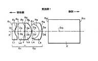
ここで、図1は本発明の実施形態1を代表させるものとして実施例1のレンズ基本構成を示すものである。
【0014】
図1に示すように、本実施形態1に係る内視鏡用対物レンズは、物体側より順に、少なくとも1枚の負の屈折力を有するレンズを含む第1レンズ群G1と、絞り1と、正の屈折力を有する第2レンズ群G2とが配され、第1レンズ群G1は回折光学面を有する少なくとも1枚の負の屈折力のレンズを含み、以下の条件式(1)および(2)を満足するように構成されている。
(1) E > 0
(2) -2.0 < fN/f < -0.3
ただし、
E :回折光学面の位相差関数の2次の項の係数
fN:第1レンズ群G1中、回折光学面を有し最も強い負の屈折力を有するレンズの焦点距離
f :レンズ全系の焦点距離
【0015】
ここで、実施例1に係る内視鏡用対物レンズの構成は、第1レンズ群G1は物体側より順に、像側に凹面を向けた平凹レンズからなる第1レンズL1、および物体側に凸面を向けた凸メニスカスレンズからなる第2レンズL2からなり、第2レンズ群G2は物体側より順に、像側に凸面を向け物体側の平面に絞り1が形成された平凸レンズからなる第3レンズL3、および像側に凸面を向けた凸メニスカスレンズからなる第4レンズL4と像側に凸面を向けた凹メニスカスレンズからなる第5レンズL5との接合レンズからなる。なお、実施例1および以下の他の実施例において、絞り1の曲率半径は無限大とされている。
【0016】
また、第2レンズ群G2の像側にはフィルタ部2が配され、さらに図示されない像側にはCCD素子やイメージファイバが配されて画像情報が伝達される。なお、図1中Xは光軸を示す。
【0017】
本実施形態1に係る内視鏡用対物レンズは、第1レンズ群G1のうちの少なくとも1枚の負レンズに、下記に示す回折光学面の非球面形状式および位相差関数式により表される回折光学面を備えている。実施例1に係る内視鏡用対物レンズは、第1レンズL1の像側の面が回折光学面とされている。
【0018】
【数1】
なお、この回折光学面による現実の光路差を規定する回折光学面光路差関数は、波長をλ、位相差関数をΦ(Y)として、λ×Φ(Y)/2πで表わされる。
【0020】
前述したとおり、回折光学面は逆分散性および異常分散性という特性を有するものである。回折光学面を備えた本実施形態1に係る内視鏡用対物レンズは、この特性を利用することにより倍率色収差を効果的に補正することができる。
【0021】
また、本実施形態1に係る内視鏡用対物レンズは、設定波長をd線(587.6nm)とすることが望ましく、この波長としたとき回折光学面により生じた+1次光が最も効率よく絞り1付近で収束する。絞り1の開口部を所定の大きさとし、回折光学面を絞り1よりも物体側に配置することにより、絞り1を透過するのは+1次光のほぼ全光量のみとなり、不要光の大部分を絞り1によりカットすることができる。ここでいう不要光とは、例えば、回折光学面によって生じる0次、一次および2次以上の高次数の回折光でレンズ設計上利用されない光や、レンズの製造誤差等により生ずるフレア光のことで、これらの光はレンズの高解像化を妨げる原因ともなるものである。なお、厳密には、例えば回折光学面を透過した0次光のごく一部も絞り1開口部を透過するが、その光量は絞り1を透過する全光量のうちごく小さい割合であるため無視できる。
【0022】
ここで、各条件式について説明する。
【0023】
条件式(1)は回折光学面の位相差関数の2次の項の係数について数値範囲を規定している。この数値範囲を規定することによりレンズ系の負の倍率色収差を良好に補正することが可能となり、この下限値を超えるとさらに負の倍率色収差が増えてしまう。
【0024】
条件式(2)は第1レンズ群G1中の回折光学面を有するレンズのうち、最も強い負の屈折力を有するレンズのパワーを規定している。回折光学面を強い負のパワーを有するレンズに形成する場合、この数値範囲に規定されるパワー配分とすることにより諸収差をバランス良く補正することができる。この下限値を超えるとバックフォーカスが短くなりすぎ、この上限値を超えると負のパワーが強くなりすぎて収差補正が困難になる。
【0025】
内視鏡用対物レンズにおいては、広画角でバックフォーカスの長いレンズが要求されるため、レトロフォーカスタイプのレンズが使用されるのが一般的である。そのため、第1レンズ群G1中にある程度強い負のパワーを有するレンズを配して必要なバックフォーカスを確保することになるが、本実施形態1においては、この第1レンズ群G1中の強い負のパワーを有するレンズに回折光学面を形成して、簡易な構成で良好な倍率色収差補正を可能にするものである。
【0026】
つぎに、本発明の実施形態2について図面を用いて説明する。
【0027】
ここで、図4は本発明の実施形態2を代表させるものとして実施例4のレンズ基本構成を示すものである。
【0028】
図4に示すように、本実施形態2に係る内視鏡用対物レンズは、物体側より順に、少なくとも1枚の負の屈折力を有するレンズを含む第1レンズ群G1と、絞り1と、正の屈折力を有する第2レンズ群G2とが配され、第1レンズ群G1は回折光学面を有する少なくとも1枚の負の屈折力のレンズを含み、以下の条件式(1)および(3)を満足するように構成されている。
(1) E > 0
(3) fN/f < -100
ただし、
E :回折光学面の位相差関数の2次の項の係数
fN:第1レンズ群G1中、回折光学面を有しレンズのうち最も強い負の屈折力を有するレンズの焦点距離
f :レンズ全系の焦点距離
【0029】
ここで、実施例4に係る内視鏡用対物レンズの構成は、第1レンズ群G1は物体側より順に、像側に凹面を向けた平凹レンズからなる第1レンズL1、および両面ともに平面で物体側に回折光学面を形成された第2レンズL2からなり、第2レンズ群G2は物体側より順に、像側に曲率の大きい面を向けた両凸レンズからなる第3レンズL3、および像側に曲率の大きい面を向けた両凸レンズからなる第4レンズL4と像側に凸面を向けた凹メニスカスレンズからなる第5レンズL5との接合レンズからなる。ここで、絞り1は近軸上において第2レンズL2の像側の面頂点に接する位置に配されている。なお、その他の構成および回折光学面の非球面形状式および位相差関数式は実施形態1と略同様である。
【0030】
実施形態2においても、回折光学面を利用することにより、倍率色収差を効果的に補正することができる。また、この回折光学面を絞り1よりも物体側に配置し、実施形態1と同様の設定波長とすることにより、不要光の大部分を絞り1によりカットすることができ、レンズの高解像化を図ることができる。
【0031】
また、条件式(3)は、第1レンズ群G1中の回折光学面を有するレンズのうち、最も強い負の屈折力を有するレンズのパワーを規定している。回折光学面を平面形状のレンズ面に形成する場合、この面のパワーは面の屈折系のパワーが大略0であることから回折光学面の有するパワーに依存することになる。条件式(1)によりE>0であるため、この回折光学面の有するパワーは負となるが、条件式(3)の数値範囲に規定されるパワー配分とすることにより、諸収差をバランス良く補正することができる。この上限値を超えプレート回折光学面のパワーが強くなると、他の屈折レンズとのバランスが崩れ、収差補正が困難になる。また、この上限値を超えプレート回折光学面のパワーを強くするためには、回折光学面の輪帯ピッチを細かくする必要があるため、製造性が不良となる。
【0032】
つぎに、本発明の実施形態3について図面を用いて説明する。
【0033】
ここで、図5は本発明の実施形態3を代表させるものとして実施例5のレンズ基本構成を示すものである。
【0034】
図5に示すように、本実施形態3に係る内視鏡用対物レンズは、物体側より順に、少なくとも1枚の負の屈折力を有するレンズを含む第1レンズ群G1と、絞り1と、正の屈折力を有する第2レンズ群G2とが配され、第1レンズ群G1は、回折光学面を有する少なくとも1枚の正の屈折力のレンズを含み、以下の条件式(4)および(5)を満足するように構成されている。
(4) E > 0
(5) 1.0 < fP/f
ただし、
E :回折光学面の位相差関数の2次の項の係数
fP:第1レンズ群G1中、回折光学面を有しレンズのうち最も強い正の屈折力を有するレンズの焦点距離
f :レンズ全系の焦点距離
【0035】
ここで、実施例5に係る内視鏡用対物レンズの構成は、第1レンズ群G1は物体側より順に、像側に凹面を向けた平凹レンズからなる第1レンズL1、および物体側に凸面を向けた正メニスカスレンズからなる第2レンズL2からなり、第2レンズ群G2は物体側より順に、像側に凸面を向け物体側の平面に絞り1が形成された平凸レンズからなる第3レンズL3、および像側に凸面を向けた平凸レンズからなる第4レンズL4と像側に凸面を向けた凹メニスカスレンズからなる第5レンズL5との接合レンズからなる。実施例5に係る内視鏡用対物レンズは、第2レンズL2の物体側の面が回折光学面とされている。なお、その他の構成および回折光学面の非球面形状式および位相差関数式は実施形態1と略同様である。
【0036】
実施形態3においても、回折光学面を利用することにより、倍率色収差を効果的に補正することができる。また、この回折光学面を絞り1よりも物体側に配置し、実施形態1と同様の設定波長とすることにより不要光の大部分を絞り1によりカットすることができ、レンズの高解像化を図ることができる。
【0037】
条件式(5)は、第1レンズ群G1中の回折光学面を有するレンズのうち、最も強い正の屈折力を有するレンズのパワーを規定している。回折光学面は、必ずしも負の屈折力を有する面に形成される必要はなく、本実施形態3に示すように正の屈折力を有する面であってもよい。この場合、負の屈折力を有する第1レンズ群G1の中で正の屈折力を有するレンズということになり、諸収差をバランス良く補正しつつ、必要なバックフォーカスを確保するために条件式(5)の数値範囲が必要となる。この下限値を超えるとバックフォーカスが短くなりすぎてしまう。
【0038】
以下、本発明の実施例1〜7について具体的に説明する。
【0039】
<実施例1>
本実施例1に係る内視鏡用対物レンズの構成は前述したとおりである。
【0040】
表1に、本実施例1の各レンズ面の曲率半径R(mm)、各レンズの軸上面間隔(各レンズの中心厚および各レンズ間の空気間隔)D(mm)、各レンズのd線における屈折率N、およびアッベ数νを示す。また、表1の下段には本実施例1における上記回折光学面の非球面形状式および位相差関数式に示される回折光学面の各定数の値を示す。
【0041】
なお、実施例1〜7において、レンズ系全体の焦点距離fは1.00mmとされている。また、表1および以下の表において、各記号に対応させた数字は物体側から順次増加するようになっており、数字の左側の*印は回折光学面であることを示す。
【0042】
【表1】
本実施例1において条件式(1)および(2)に対応する値はE=4.8154×10⁻¹、fN/f=-0.72となり、各条件式をすべて満足している。
【0044】
<実施例2>
本実施例2に係る内視鏡用対物レンズは実施形態1に上述した構成とされているが、実施例1とはレンズ構成が異なる。
【0045】
ここで、第1レンズ群G1は像側に凹面を向けた平凹レンズからなる第1レンズL1からなり、第2レンズ群G2は物体側より順に、像側に凸面を向け物体側の平面に絞り1が形成された平凸レンズからなる第2レンズL2、および像側に曲率の大きい面を向けた両凸レンズからなる第3レンズL3と像側に凸面を向けた凹メニスカスレンズからなる第4レンズL4との接合レンズからなる。
【0046】
なお、実施例2に係る内視鏡用対物レンズは、第1レンズL1の像側の面に回折光学面を備えている。
【0047】
表2に、本実施例2の各レンズ面の曲率半径R(mm)、各レンズの軸上面間隔(各レンズの中心厚および各レンズ間の空気間隔)D(mm)、各レンズのd線における屈折率N、およびアッベ数νを示す。また、表2の下段には本実施例2における上記回折光学面の非球面形状式および位相差関数式に示される回折光学面の各定数の値を示す。
【0048】
【表2】
本実施例2において条件式(1)および(2)に対応する値はE=4.7550×10⁻¹、fN/f=-0.90となり、各条件式をすべて満足している。
【0050】
<実施例3>
本実施例3に係る内視鏡用対物レンズは実施形態1に上述した構成とされているが、実施例1とはレンズ構成が異なる。
【0051】
ここで、第1レンズ群G1は物体側より順に、像側に凹面を向けた平凹レンズからなる第1レンズL1、および像側に凸面を向けた凸メニスカスレンズからなる第2レンズL2からなり、第2レンズ群G2は物体側より順に、像側に凹面を向け物体側の平面に絞り1が形成された平凹レンズからなる第3レンズL3と物体側に曲率の大きい面を向けた両凸レンズからなる第4レンズL4との接合レンズからなる。
【0052】
なお、実施例3に係る内視鏡用対物レンズは、第1レンズL1の像側の面に回折光学面を備えている。
【0053】
表3に、本実施例3の各レンズ面の曲率半径R(mm)、各レンズの軸上面間隔(各レンズの中心厚および各レンズ間の空気間隔)D(mm)、各レンズのd線における屈折率N、およびアッベ数νを示す。また、表3の下段には本実施例3における上記回折光学面の非球面形状式および位相差関数式に示される回折光学面の各定数の値を示す。
【0054】
【表3】
本実施例3において条件式(1)および(2)に対応する値はE=1.0501×10⁻²、fN/f= -1.11となり、各条件式をすべて満足している。
【0056】
<実施例4>
本実施例4に係る内視鏡用対物レンズの構成は前述したとおりである。
【0057】
表4に、本実施例4の各レンズ面の曲率半径R(mm)、各レンズの軸上面間隔(各レンズの中心厚および各レンズ間の空気間隔)D(mm)、各レンズのd線における屈折率N、およびアッベ数νを示す。また、表4の下段には本実施例4における上記回折光学面の非球面形状式および位相差関数式に示される回折光学面の各定数の値を示す。
【0058】
【表4】
本実施例4において条件式(1)および(3)に対応する値はE=7.5022×10⁻³、fN/f=-7.13×105となり、各条件式をすべて満足している。
【0060】
<実施例5>
本実施例5に係る内視鏡用対物レンズの構成は前述したとおりである。
【0061】
表5に、本実施例5の各レンズ面の曲率半径R(mm)、各レンズの軸上面間隔(各レンズの中心厚および各レンズ間の空気間隔)D(mm)、各レンズのd線における屈折率N、およびアッベ数νを示す。また、表5の下段には本実施例5における上記回折光学面の非球面形状式および位相差関数式に示される回折光学面の各定数の値を示す。
【0062】
【表5】
本実施例5において条件式(4)および(5)に対応する値はE=2.2001×10⁻²、fP/f=3.35となり、各条件式をすべて満足している。
【0064】
<実施例6>
本実施例6に係る内視鏡用対物レンズは実施形態3に上述した構成とされているが、実施例5とはレンズ構成が異なる。
【0065】
ここで、第1レンズ群G1は物体側より順に、像側に凹面を向けた平凹レンズからなる第1レンズL1、および像側に曲率の大きい面を向けた両凸レンズからなる第2レンズL2からなり、第2レンズ群G2は物体側より順に、像側に凹面を向け物体側の平面に絞り1が形成された平凹レンズからなる第3レンズL3と物体側に曲率の大きい面を向けた両凸レンズからなる第4レンズL4との接合レンズからなる。
【0066】
なお、実施例6に係る内視鏡用対物レンズは、第2レンズL2の物体側の面に回折光学面を備えている。
【0067】
表6に、本実施例6の各レンズ面の曲率半径R(mm)、各レンズの軸上面間隔(各レンズの中心厚および各レンズ間の空気間隔)D(mm)、各レンズのd線における屈折率N、およびアッベ数νを示す。また、表6の下段には本実施例6における上記回折光学面の非球面形状式および位相差関数式に示される回折光学面の各定数の値を示す。
【0068】
【表6】
本実施例6において条件式(4)および(5)に対応する値はE=3.8070×10⁻³、fP/f=1.84となり、各条件式をすべて満足している。
【0070】
<実施例7>
本実施例7に係る内視鏡用対物レンズの構成は、上述の実施形態1と実施形態3をともに満足するものである。すなわち、第1レンズ群G1中で、正の屈折力のレンズと負の屈折力のレンズに各々回折光学面を有し、条件式(1)、(2)および(5)を満足する。なお、条件式(4)は条件式(1)と同様であるので省略する。
【0071】
ここで、第1レンズ群G1は物体側より順に、像側に凹面を向けた平凹レンズからなる第1レンズL1、および物体側に凸面を向けた正メニスカスレンズからなる第2レンズL2からなり、第2レンズ群G2は物体側より順に、像側に凸面を向け物体側の平面に絞り1が形成された平凸レンズからなる第3レンズL3、および像側に凸面を向けた平凸レンズからなる第4レンズL4と像側に凸面を向けた凹メニスカスレンズからなる第5レンズL5との接合レンズからなる。ここで、回折光学面は、第1レンズL1と第2レンズL2の各々物体側の面である。なお、その他の構成ならびに回折光学面の非球面形状式および位相差関数式は実施形態1および実施形態3と略同様である。
【0072】
表7に、本実施例7の各レンズ面の曲率半径R(mm)、各レンズの軸上面間隔(各レンズの中心厚および各レンズ間の空気間隔)D(mm)、各レンズのd線における屈折率N、およびアッベ数νを示す。また、表7の下段には本実施例7における上記回折光学面の非球面形状式および位相差関数式に示される回折光学面の各定数の値を示す。
【0073】
【表7】
本実施例7において条件式(1)、(2)および(5)に対応する値は第1レンズL1のE=2.2127×10⁻²、第2レンズL2のE=1.6499×10⁻²、fN/f=-0.61、fP/f=3.46となり、各条件式をすべて満足している。
【0075】
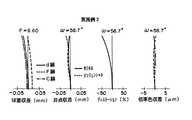
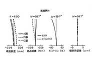
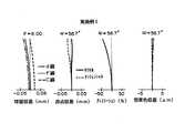
図8〜14は、本実施例1〜7に係る内視鏡用対物レンズの諸収差(球面収差、非点収差、ディストーションおよび倍率色収差)を示す収差図である。なお、これらの収差図においてωは半画角を示す。
【0076】
図8〜14に示すように、本実施例1〜7に係る内視鏡用対物レンズは、収差、特に倍率色収差を良好に補正したものであることが明らかである。
【0077】
なお、本発明の内視鏡用対物レンズとしては、上記実施例のものに限られるものではなく種々の態様の変更が可能であり、例えば各レンズの曲率半径Rおよびレンズ間隔(もしくはレンズ厚)Dを適宜変更することが可能である。
【0078】
【発明の効果】
以上説明したように、本発明に係る内視鏡用対物レンズによれば、回折光学面を用いることにより特に倍率色収差を良好に補正し、また、その回折光学面を絞りより物体側に配設することにより、回折光学面を用いたために生じる設計上では不要な光となる回折光や、製造誤差等で生じるフレア光等の悪影響を低減させ、高解像化に適用可能な内視鏡用対物レンズを得ることができる。
【図面の簡単な説明】
【図1】実施例1に係る内視鏡用対物レンズの構成を示す図
【図2】実施例2に係る内視鏡用対物レンズの構成を示す図
【図3】実施例3に係る内視鏡用対物レンズの構成を示す図
【図4】実施例4に係る内視鏡用対物レンズの構成を示す図
【図5】実施例5に係る内視鏡用対物レンズの構成を示す図
【図6】実施例6に係る内視鏡用対物レンズの構成を示す図
【図7】実施例7に係る内視鏡用対物レンズの構成を示す図
【図8】実施例1に係る内視鏡用対物レンズの各収差図
【図9】実施例2に係る内視鏡用対物レンズの各収差図
【図10】実施例3に係る内視鏡用対物レンズの各収差図
【図11】実施例4に係る内視鏡用対物レンズの各収差図
【図12】実施例5に係る内視鏡用対物レンズの各収差図
【図13】実施例6に係る内視鏡用対物レンズの各収差図
【図14】実施例7に係る内視鏡用対物レンズの各収差図
【符号の説明】
L1〜L5 レンズ
G1,G2 レンズ群
R1〜R11 曲率半径
D1〜D10 軸上面間隔
X 光軸
1 絞り
2 フィルタ部[0001]
BACKGROUND OF THE INVENTION
The present invention relates to an objective lens provided at a distal end portion of an endoscope, and more particularly to an endoscope objective lens corresponding to a high-resolution imaging element used for transmitting image information. .
[0002]
[Prior art]
In general, an endoscope objective lens is required to have a wide angle of view and a long back focus. In addition, correction of chromatic aberration is important for performing highly accurate observation and accurate diagnosis. In order to satisfy these requirements, for example, the present applicant has already disclosed an endoscope objective lens described in JP-A-2-188709.
[0003]
However, in recent years, with higher resolution of CCD elements and image fibers used for image transmission, lenses with higher resolution have been demanded. The endoscope objective lens described in Japanese Patent Laid-Open No. 2-188709 needs to further improve lateral chromatic aberration in consideration of high resolution of elements used for image transmission.
[0004]
An objective lens using an optical system having a diffractive optical surface (hereinafter referred to as a diffractive optical element) is also known as means for correcting chromatic aberration. The Abbe number of the diffractive optical element is νd = −3.45, and the dispersion is larger as the digit is different from that of a normal glass lens, and the sign is also different. Therefore, the chromatic aberration can be corrected as effectively as cannot be expected with a normal lens. There are advantages. An example of such an endoscope objective lens is disclosed in Japanese Patent Application Laid-Open No. 10-197806.
[0005]
[Problems to be solved by the invention]
However, in the endoscope objective lens described in Japanese Patent Application Laid-Open No. 10-197806, diffracted light of other orders which is generated by using a diffractive optical element and becomes unnecessary light in design, or flare light generated by a manufacturing error, etc. Etc. have a problem of adversely affecting high resolution.
[0006]
The present invention has been made in view of such circumstances, and by using a diffractive optical element, while reducing aberrations, in particular lateral chromatic aberration, satisfactorily, light that adversely affects such high resolution has been reduced. An object of the present invention is to provide an endoscope objective lens.
[0007]
[Means for Solving the Problems]
An endoscope objective lens according to the present invention,
In order from the object side, a first lens group including a lens having at least one negative refracting powerwith a diffractive optical surface, a stop, and a second lens group having a positive refractive powerarranged, the diffraction The optical surface satisfies the following conditional expression (1),
The lens having the strongest negative refracting power among the lenses having the negative refracting power provided with the diffractive optical surface in the first lens group is configured tosatisfy the following conditional expression (2). It is characterized by this.
(1) E> 0
(2) -2.0 <f N / f <-0.3
However,
E: Coefficient of second order term of phase difference function of diffractive optical surface
fN: the focal length of the lens having the diffractive optical surface and the strongest negative refractive power in the first lens group
f: Focal length of the entire lens system
Moreover, the objective lens for an endoscope according to the present invention is:
In order from the object side, a first lens group including at least one lens having a diffractive optical surface and having a negative refractive power, a stop, and a second lens group having a positive refractive power are arranged. The optical surface is configured to satisfy the following conditional expression (1),
Lens having the strongest negative refractive power of the lenshaving a negative refractive power having a diffractive optical surface of thefront SL in the first lens group, it is configured so as to satisfy the following conditional expression (3) It is characterized by.
(1) E> 0
(3) f N / f < -100
However,
E: Coefficient of second-order term of phase difference function of diffractive optical surface fN : Focal length of lens having diffractive optical surface and having strongest negative refractive power in first lens group f: Focal point of entire lens system Distance [0010]
The endoscope objective lens according to the present invention includes, in order from the object side, a first lens group including at least one lens having negative refractive power, a diaphragm, and a second lens having positive refractive power. and the group is arranged, the first lens group includes at least one positive lenshaving a refractive powerwith a diffractive optical surface, the diffractive optical surfacepositive refractive provided with in said first lens groupThe lenshaving the strongest positive refractive power among the lenseshaving power is configured to satisfy the following conditional expressions (4) and (5).
(4) E> 0
(5) 1.0 <f P / f
However,
E: Coefficient of the second-order term of the phase difference function of the diffractive optical surface fP : Focal length of the lens having the diffractive optical surface and the strongest positive refractive power in the first lens group f: Focal point of the entire lens system Distance [0011]
Here, the “phase difference function of the diffractive optical surface” is represented by Φ (Y) = EY2 + FY4 + GY6 + HY8 + IY10 .
[0012]
DETAILED DESCRIPTION OF THE INVENTION
Hereinafter,
[0013]
Here, FIG. 1 shows the basic lens configuration of Example 1 as representative of
[0014]
As shown in FIG. 1, the endoscope objective lens according to the first embodiment includes, in order from the object side, a first lens group G1 including at least one lens having negative refractive power, an
(1) E> 0
(2) -2.0 <f N / f <-0.3
However,
E: Coefficient of second-order term of phase difference function of diffractive optical surface fN : Focal length f of lens having diffractive optical surface and strongest negative refractive power in first lens group G1 : Entire lens system Focal length of
Here, the configuration of an endoscope objective lens according to Example 1, the first lens group G1 includes, in order from the object side, a first lens L1, and the object-side consisting of plano-concave lens with a concave surface facing the image side the convex surface consists second lens L2 formed of a convex meniscus lens, a second lens group G2 includes, in order from the object side, a plano-
[0016]
Further, the image side of the second lens group G2 filter section 2 is disposed, further image information is arranged for CCD elements or image fiber on the image side which is not shown is transmitted. In FIG. 1, X indicates an optical axis.
[0017]
An objective lens for an endoscope according to the first embodiment, at least one negative lens of the first lens group G1, represented by the aspherical equation and phase difference function equation of the diffractive optical surface shown in the following A diffractive optical surface. An endoscope objective lens according to Example 1, the image-side surface of the first lens L1 is a diffractive optical surface.
[0018]
[Expression 1]
The diffractive optical surface optical path difference function that defines the actual optical path difference due to this diffractive optical surface is expressed by λ × Φ (Y) / 2π, where λ is the wavelength and Φ (Y) is the phase difference function.
[0020]
As described above, the diffractive optical surface has characteristics of reverse dispersion and anomalous dispersion. The endoscope objective lens according to the first embodiment having the diffractive optical surface can effectively correct the lateral chromatic aberration by using this characteristic.
[0021]
In the endoscope objective lens according to the first embodiment, it is desirable that the set wavelength is the d-line (587.6 nm), and the + 1st-order light generated by the diffractive optical surface is most efficiently stopped at this wavelength. Converge around 1. By setting the aperture of the
[0022]
Here, each conditional expression will be described.
[0023]
Conditional expression (1) defines a numerical range for the coefficient of the second-order term of the phase difference function of the diffractive optical surface. By defining this numerical value range, it is possible to satisfactorily correct the negative magnification chromatic aberration of the lens system. If this lower limit is exceeded, the negative magnification chromatic aberration further increases.
[0024]
Condition (2) defines the power of the lens having one, the strongest negative refractive power of the lens having a diffractive optical surface in the G1 the first lens group. When the diffractive optical surface is formed on a lens having a strong negative power, various aberrations can be corrected in a well-balanced manner by using a power distribution defined in this numerical range. When this lower limit is exceeded, the back focus becomes too short, and when this upper limit is exceeded, the negative power becomes too strong and aberration correction becomes difficult.
[0025]
In an endoscope objective lens, since a lens having a wide angle of view and a long back focus is required, a retrofocus type lens is generally used. Therefore, it becomes possible to maintain the necessary back focus by arranging a lens having a first lens group G1 a somewhat strong negative power in, in the
[0026]
Next,
[0027]
Here, FIG. 4 shows the basic lens configuration of Example 4 as representative of
[0028]
As shown in FIG. 4, the endoscope objective lens according to the second embodiment includes, in order from the object side, a first lens group G1 including at least one lens having negative refractive power, an
(1) E> 0
(3) f N / f < -100
However,
E: Coefficient of second-order term of phase difference function of diffractive optical surface fN : Focal length f of lens having diffractive optical surface and the strongest negative refractive power among lenses in first lens group G1 : Focal length of the entire lens system [0029]
Here, the configuration of an endoscope objective lens according to Example 4, in order from the first lens group G1 is the object side, a first lens L1 composed of a plano-concave lens having a concave surface facing the imageside, and the both surfaces The second lens L2 is a flat surface formed with a diffractive optical surface on the object side, and the second lens group G2 is a third lens L composed of a biconvex lens having a surface with a large curvature facing the image side in order from the object side.3, and a cemented lens of a fifth lens L5 formed of the fourth lens L4 and a concave meniscus lens having a convex surface directed toward the image side, which is a biconvex lens having a surface with a greater curvature to the image side. Here, the
[0030]
In the second embodiment, the chromatic aberration of magnification can be effectively corrected by using the diffractive optical surface. Further, by arranging this diffractive optical surface on the object side with respect to the
[0031]
The conditional expression (3), of the lens having a diffractive optical surface of the first lens group G1, defines the power of the lens having the strongest negative refractive power. When the diffractive optical surface is formed on a planar lens surface, the power of this surface depends on the power of the diffractive optical surface because the power of the refractive system of the surface is approximately zero. Since E> 0 according to the conditional expression (1), the power of the diffractive optical surface is negative. However, various aberrations are balanced with the power distribution defined in the numerical range of the conditional expression (3). It can be corrected. If the power of the plate diffractive optical surface is increased beyond this upper limit, the balance with other refractive lenses is lost, and aberration correction becomes difficult. Further, in order to increase the power of the plate diffractive optical surface beyond this upper limit, it is necessary to make the ring pitch of the diffractive optical surface finer, resulting in poor productivity.
[0032]
Next, Embodiment 3 of the present invention will be described with reference to the drawings.
[0033]
Here, FIG. 5 shows a basic lens configuration of Example 5 as representative of Embodiment 3 of the present invention.
[0034]
As shown in FIG. 5, the endoscope objective lens according to the third embodiment includes, in order from the object side, a first lens group G1 including at least one lens having negative refractive power, an
(4) E> 0
(5) 1.0 <f P / f
However,
E: Coefficient of second-order term of phase difference function of diffractive optical surface fP :
Here, the configuration of an endoscope objective lens according to Example 5, the first lens group G1 includes, in order from the object side, a first lens L1, and the object-side consisting of plano-concave lens with a concave surface facing the image side the convex surface consists second lens L2, which is a positive meniscus lens, the second lens group G2 includes, in order from the object side, a plano-
[0036]
In the third embodiment, the chromatic aberration of magnification can be effectively corrected by using the diffractive optical surface. Further, by arranging this diffractive optical surface on the object side with respect to the
[0037]
Condition (5), of the lens having a diffractive optical surface of the first lens group G1, defines the power of the lens having the strongest positive refractive power. The diffractive optical surface is not necessarily formed on a surface having negative refractive power, and may be a surface having positive refractive power as shown in the third embodiment. In this case, the fact that the lens having a positive refractive power in the first lens group G1 having a negative refractive power, while the aberrations well-balanced correction, conditional expressions in order to secure the necessary back focus The numerical range of (5) is required. If this lower limit is exceeded, the back focus will be too short.
[0038]
Examples 1 to 7 of the present invention will be specifically described below.
[0039]
<Example 1>
The configuration of the endoscope objective lens according to Example 1 is as described above.
[0040]
Table 1 shows the radius of curvature R (mm) of each lens surface of Example 1, the axial top surface distance (center thickness of each lens and the air space between each lens) D (mm), and the d-line of each lens. Shows the refractive index N and Abbe number ν. The lower part of Table 1 shows the values of the constants of the diffractive optical surface shown in the aspheric shape formula and the phase difference function formula of the diffractive optical surface in Example 1.
[0041]
In Examples 1 to 7, the focal length f of the entire lens system is 1.00 mm. In Table 1 and the following table, the numbers corresponding to the respective symbols are sequentially increased from the object side, and the * mark on the left side of the numbers indicates a diffractive optical surface.
[0042]
[Table 1]
In Example 1, values corresponding to the conditional expressions (1) and (2) are E = 4.8154 × 10⁻¹ and fN /f=−0.72, which satisfy all the conditional expressions.
[0044]
<Example 2>
The endoscope objective lens according to Example 2 is configured as described above in
[0045]
Here, the first lens group G1 is composed of first lens L1 composed of a plano-concave lens having a concave surface facing the image side, the second lens group G2 includes, in order from the object side, the object side convex surface directed toward the image side A second lens L2 composed of a plano-convex lens having a
[0046]
Incidentally, the endoscope objective lens according to Example 2 has a diffractive optical surface on the surface of the first lens L1 on the image side.
[0047]
Table 2 shows the radius of curvature R (mm) of each lens surface of Example 2, the axial top surface distance (center thickness of each lens and the air space between each lens) D (mm), and the d-line of each lens. Shows the refractive index N and Abbe number ν. The lower part of Table 2 shows the values of the constants of the diffractive optical surface shown in the aspheric shape formula and the phase difference function formula of the diffractive optical surface in Example 2.
[0048]
[Table 2]
In Example 2, values corresponding to the conditional expressions (1) and (2) are E = 4.7550 × 10⁻¹ and fN /f=−0.90, which satisfy all the conditional expressions.
[0050]
<Example 3>
The endoscope objective lens according to Example 3 is configured as described in
[0051]
Here, in order from the object side, the first lens group G1 is a first lens L1 composed of a plano-concave lens having a concave surface facing the image side, and a second lens L2 composed of a convex meniscus lens having a convex surface facing the image side. from it, the second lens group G2 includes, in order from the object side, a surface with a greater curvature to the third lens L3 and the object side consisting of a plano-concave lens the
[0052]
Incidentally, the endoscope objective lens according to Example 3 has a diffractive optical surface on the surface of the first lens L1 on the image side.
[0053]
Table 3 shows the radius of curvature R (mm) of each lens surface of Example 3, the axial top surface spacing (center thickness of each lens and the air spacing between each lens) D (mm), and the d-line of each lens. Shows the refractive index N and Abbe number ν. The lower part of Table 3 shows the values of the constants of the diffractive optical surface shown in the aspheric shape formula and the phase difference function formula of the diffractive optical surface in Example 3.
[0054]
[Table 3]
Values corresponding to the conditional expressions in the embodiment 3 (1) and (2) E = 1.0501 × 10- satisfies2,f N/ f = -1.11, and the respective conditional expressions all.
[0056]
<Example 4>
The configuration of the endoscope objective lens according to Example 4 is as described above.
[0057]
Table 4 shows the radius of curvature R (mm) of each lens surface of Example 4, the axial top surface spacing (center thickness of each lens and the air spacing between each lens) D (mm), and the d-line of each lens. Shows the refractive index N and Abbe number ν. The lower part of Table 4 shows the values of the constants of the diffractive optical surface shown in the aspheric shape formula and the phase difference function formula of the diffractive optical surface in Example 4.
[0058]
[Table 4]
In Example 4, the values corresponding to the conditional expressions (1) and (3) are E = 7.5022 × 10⁻³ and fN /f=−7.13×105 , and all the conditional expressions are satisfied.
[0060]
<Example 5>
The configuration of the endoscope objective lens according to Example 5 is as described above.
[0061]
Table 5 shows the radius of curvature R (mm) of each lens surface of Example 5, the distance between the axial upper surfaces of each lens (the center thickness of each lens and the air space between each lens) D (mm), and the d line of each lens. Shows the refractive index N and Abbe number ν. The lower part of Table 5 shows the values of the constants of the diffractive optical surface shown in the aspherical shape formula and phase difference function formula of the diffractive optical surface in Example 5.
[0062]
[Table 5]
Values corresponding to the conditional expressions in the embodiment 5 (4) and (5) E = 2.2001 × 10- satisfies2, fP/f=3.35 next, the respective conditional expressions all.
[0064]
<Example 6>
The endoscope objective lens according to Example 6 has the configuration described above in Embodiment 3, but the lens configuration is different from Example 5.
[0065]
Here, the first lens group G1 is, in order from the object side, a first lens L1 composed of a plano-concave lens having a concave surface facing the image side, and a second lens composed of a biconvex lens having a large curvature surface facing the image side. consist L2, in order from the second lens group G2 is the object side, a large curvature to the third lens L3 and the object side consisting of concave lens where the first diaphragm to the plane of the object-side concave surface facing the image side is formed a cemented lens of a fourth lens L4, which is a biconvex lens having a surface.
[0066]
Incidentally, the objective lens for an endoscope according to the sixth embodiment is provided with a diffractive optical surface on the surface of the second lens L2 on the object side.
[0067]
Table 6 shows the curvature radius R (mm) of each lens surface of Example 6, the axial top surface spacing (center thickness of each lens and the air spacing between each lens) D (mm), and the d-line of each lens. Shows the refractive index N and Abbe number ν. The lower part of Table 6 shows the values of the constants of the diffractive optical surface shown in the aspheric shape formula and the phase difference function formula of the diffractive optical surface in Example 6.
[0068]
[Table 6]
In Example 6, the values corresponding to the conditional expressions (4) and (5) are E = 3.8070 × 10⁻³ and fP /f=1.84, which satisfy all the conditional expressions.
[0070]
<Example 7>
The configuration of the endoscope objective lens according to Example 7 satisfies both the above-described first and third embodiments. That is, the first in lens group G1, each have a diffractive optical surface in the positive refractive power of the lens and the negative refractive power of the lens, the conditional expression (1) satisfies (2) and (5). Since conditional expression (4) is the same as conditional expression (1), it is omitted.
[0071]
Here, in order from the object side, the first lens group G1 is a first lens L1 composed of a plano-concave lens having a concave surface facing the image side, and a second lens L2 composed of a positive meniscus lens having a convex surface facing the object side. The second lens group G2 has, in order from the object side, a third lens L3 composed of a planoconvex lens having a convex surface facing the image side and a
[0072]
Table 7 shows the radius of curvature R (mm) of each lens surface of Example 7, the axial top surface distance (center thickness of each lens and the air space between each lens) D (mm), and the d-line of each lens. Shows the refractive index N and Abbe number ν. The lower part of Table 7 shows the values of the constants of the diffractive optical surface shown in the aspheric shape formula and the phase difference function formula of the diffractive optical surface in Example 7.
[0073]
[Table 7]
Condition In the present Example 7 (1), (2) and (5) the corresponding value of the first lensL 1 E = 2.2127 × 10 -2 , the second lensL 2 E = 1.6499 × 10⁻² FN /f=−0.61 and fP /f=3.46, and all the conditional expressions are satisfied.
[0075]
8 to 14 are aberration diagrams illustrating various aberrations (spherical aberration, astigmatism, distortion, and lateral chromatic aberration) of the objective lens for endoscope according to each of Examples 1 to 7. FIG. In these aberration diagrams, ω represents a half angle of view.
[0076]
As shown in FIGS. 8 to 14, it is clear that the endoscope objective lenses according to Examples 1 to 7 are those in which aberrations, in particular, lateral chromatic aberration are corrected well.
[0077]
Note that the endoscope objective lens of the present invention is not limited to the above-described embodiment, and various modifications can be made. For example, the curvature radius R of each lens and the lens interval (or lens thickness) can be changed. D can be changed as appropriate.
[0078]
【The invention's effect】
As described above, according to the endoscope objective lens according to the present invention, the chromatic aberration of magnification is particularly favorably corrected by using the diffractive optical surface, and the diffractive optical surface is disposed closer to the object side than the stop. For endoscopes that can reduce the adverse effects of diffracted light, which is unnecessary light in design due to the use of a diffractive optical surface, and flare light that occurs due to manufacturing errors, etc., and can be applied to high resolution An objective lens can be obtained.
[Brief description of the drawings]
FIG. 1 is a diagram showing a configuration of an endoscope objective lens according to Example 1. FIG. 2 is a diagram showing a configuration of an endoscope objective lens according to Example 2. FIG. FIG. 4 is a diagram showing a configuration of an endoscope objective lens according to Example 4. FIG. 5 is a diagram showing a configuration of an endoscope objective lens according to Example 5. 6 is a diagram showing a configuration of an endoscope objective lens according to Example 6. FIG. 7 is a diagram showing a configuration of an endoscope objective lens according to Example 7. FIG. FIG. 9 is an aberration diagram of the endoscope objective lens according to Example 2. FIG. 10 is an aberration diagram of the endoscope objective lens according to Example 3. FIG. 12 shows aberrations of the endoscope objective lens according to Example 5. FIG. 13 shows aberrations of the endoscope objective lens according to Example 5. Each aberration diagrams of the endoscope objective lens according to the aberration diagrams [14] Example 7 of an object lens [Description of symbols]
L1 ~L5 lensG 1,G 2
Claims (3)
Translated fromJapanese前記第1レンズ群中の該回折光学面を備えた負の屈折力を有するレンズのうち最も強い負の屈折力を有するレンズが、以下の条件式(2)を満足するように構成されてなることを特徴とする内視鏡用対物レンズ。
(1) E > 0
(2)-2.0 < fN/f <-0.3
ただし、
E:回折光学面の位相差関数の2次の項の係数
fN:第1レンズ群中、回折光学面を有し最も強い負の屈折力を有するレンズの焦点距離
f:レンズ全系の焦点距離In order from the object side, a first lens group including at least one lens having adiffractive optical surface and having a negative refractive power, a stop, and a second lens group having a positive refractive power are disposed, While the diffractive optical surface satisfiesthe following conditional expression (1),
Among the lenses having the diffractive optical surface in the first lens group and having negative refractive power, the lens having the strongest negative refractive power is configured tosatisfy thefollowing conditional expression (2). An objective lens for an endoscope.
(1) E> 0
(2) -2.0 <f N / f <-0.3
However,
E: Coefficient of second-order term of phase difference function of diffractive optical surface
fN: the focal length of the lens having the diffractive optical surface and the strongest negative refractive power in the first lens group
f: Focal length of the entire lens system
前記第1レンズ群中の該回折光学面を備えた負の屈折力を有するレンズのうち最も強い負の屈折力を有するレンズが、以下の条件式(3)を満足するように構成されてなることを特徴とする内視鏡用対物レンズ。
(1) E > 0
(3) fN/f < -100
ただし、
E:回折光学面の位相差関数の2次の項の係数
fN:第1レンズ群中、回折光学面を有し最も強い負の屈折力を有するレンズの焦点距離
f :レンズ全系の焦点距離In order from the object side, a first lens group including at least one lens having a negative refractive power having a diffractive optical surface, a stop, and a second lens group having a positive refractive power are arranged, and the diffraction is performed. The optical surface satisfies the following conditional expression (1),
Lens having the strongest negative refractive power of the lenshaving a negative refractive power having a diffractive optical surface of thefront SL in the first lens group, it is configured so as to satisfy the following conditional expression (3) an objective lens forendoscopes characterized by comprising.
(1) E> 0
(3) f N / f < -100
However,
E: Coefficient of second order term of phase difference function of diffractive optical surface fN : Focal length of lens having diffractive optical surface and having strongest negative refractive power in first lens group f: Focal point of entire lens system distance
(4) E > 0
(5) 1.0 < fP/f
ただし、
E:回折光学面の位相差関数の2次の項の係数
fP:第1レンズ群中、回折光学面を有し最も強い正の屈折力を有するレンズの焦点距離
f :レンズ全系の焦点距離In order from the object side, a first lens group including at least one lens having a negative refractive power, a stop, and a second lens group having a positive refractive power are arranged. It includes at least one positive lenshaving a refractive powerwith an optical surface having the strongest positive refractive power of the lenshaving a positive refractive power having a diffractive optical surface in the first lens group An objective lens for an endoscope, wherein the lens is configured to satisfy the following conditional expressions (4) and (5).
(4) E> 0
(5) 1.0 <f P / f
However,
E: Coefficient of the second-order term of the phase difference function of the diffractive optical surface fP : Focal length of the lens having the diffractive optical surface and the strongest positive refractive power in the first lens group f: Focal point of the entire lens system distance
Priority Applications (2)
| Application Number | Priority Date | Filing Date | Title |
|---|---|---|---|
| JP33878298AJP4014186B2 (en) | 1998-11-30 | 1998-11-30 | Endoscope objective lens |
| US09/429,604US6181481B1 (en) | 1998-11-30 | 1999-10-29 | Objective lens for endoscope |
Applications Claiming Priority (1)
| Application Number | Priority Date | Filing Date | Title |
|---|---|---|---|
| JP33878298AJP4014186B2 (en) | 1998-11-30 | 1998-11-30 | Endoscope objective lens |
Publications (2)
| Publication Number | Publication Date |
|---|---|
| JP2000162514A JP2000162514A (en) | 2000-06-16 |
| JP4014186B2true JP4014186B2 (en) | 2007-11-28 |
Family
ID=18321425
Family Applications (1)
| Application Number | Title | Priority Date | Filing Date |
|---|---|---|---|
| JP33878298AExpired - Fee RelatedJP4014186B2 (en) | 1998-11-30 | 1998-11-30 | Endoscope objective lens |
Country Status (2)
| Country | Link |
|---|---|
| US (1) | US6181481B1 (en) |
| JP (1) | JP4014186B2 (en) |
Families Citing this family (99)
| Publication number | Priority date | Publication date | Assignee | Title |
|---|---|---|---|---|
| JP3376351B2 (en)* | 1999-11-29 | 2003-02-10 | キヤノン株式会社 | Optical system and document reading device |
| US7023622B2 (en)* | 2002-08-06 | 2006-04-04 | Dmetrix, Inc. | Miniature microscope objective lens |
| US20050245789A1 (en)* | 2003-04-01 | 2005-11-03 | Boston Scientific Scimed, Inc. | Fluid manifold for endoscope system |
| US7591783B2 (en)* | 2003-04-01 | 2009-09-22 | Boston Scientific Scimed, Inc. | Articulation joint for video endoscope |
| US7578786B2 (en)* | 2003-04-01 | 2009-08-25 | Boston Scientific Scimed, Inc. | Video endoscope |
| US20050222499A1 (en)* | 2003-04-01 | 2005-10-06 | Banik Michael S | Interface for video endoscope system |
| US8118732B2 (en) | 2003-04-01 | 2012-02-21 | Boston Scientific Scimed, Inc. | Force feedback control system for video endoscope |
| US20040199052A1 (en) | 2003-04-01 | 2004-10-07 | Scimed Life Systems, Inc. | Endoscopic imaging system |
| JP4245985B2 (en)* | 2003-05-30 | 2009-04-02 | オリンパス株式会社 | Endoscope objective lens |
| US8083671B2 (en) | 2004-09-30 | 2011-12-27 | Boston Scientific Scimed, Inc. | Fluid delivery system for use with an endoscope |
| US20060069310A1 (en)* | 2004-09-30 | 2006-03-30 | Couvillon Lucien A Jr | Programmable brake control system for use in a medical device |
| US7597662B2 (en) | 2004-09-30 | 2009-10-06 | Boston Scientific Scimed, Inc. | Multi-fluid delivery system |
| JP2008514363A (en) | 2004-09-30 | 2008-05-08 | ボストン サイエンティフィック リミテッド | Multifunctional endoscope system for use in electrosurgical applications |
| WO2006039522A2 (en)* | 2004-09-30 | 2006-04-13 | Boston Scientific Scimed, Inc. | Adapter for use with digital imaging medical device |
| US20060068360A1 (en)* | 2004-09-30 | 2006-03-30 | Scimed Life Systems, Inc. | Single use fluid reservoir for an endoscope |
| EP1799096A2 (en)* | 2004-09-30 | 2007-06-27 | Boston Scientific Scimed, Inc. | System and method of obstruction removal |
| US7479106B2 (en) | 2004-09-30 | 2009-01-20 | Boston Scientific Scimed, Inc. | Automated control of irrigation and aspiration in a single-use endoscope |
| US7241263B2 (en)* | 2004-09-30 | 2007-07-10 | Scimed Life Systems, Inc. | Selectively rotatable shaft coupler |
| US8097003B2 (en) | 2005-05-13 | 2012-01-17 | Boston Scientific Scimed, Inc. | Endoscopic apparatus with integrated variceal ligation device |
| US7846107B2 (en) | 2005-05-13 | 2010-12-07 | Boston Scientific Scimed, Inc. | Endoscopic apparatus with integrated multiple biopsy device |
| US8052597B2 (en)* | 2005-08-30 | 2011-11-08 | Boston Scientific Scimed, Inc. | Method for forming an endoscope articulation joint |
| US7967759B2 (en) | 2006-01-19 | 2011-06-28 | Boston Scientific Scimed, Inc. | Endoscopic system with integrated patient respiratory status indicator |
| US8888684B2 (en)* | 2006-03-27 | 2014-11-18 | Boston Scientific Scimed, Inc. | Medical devices with local drug delivery capabilities |
| US8202265B2 (en) | 2006-04-20 | 2012-06-19 | Boston Scientific Scimed, Inc. | Multiple lumen assembly for use in endoscopes or other medical devices |
| US7955255B2 (en)* | 2006-04-20 | 2011-06-07 | Boston Scientific Scimed, Inc. | Imaging assembly with transparent distal cap |
| DE102007044228A1 (en)* | 2007-08-17 | 2009-04-02 | Carl Zeiss Surgical Gmbh | Optical device |
| JP4695662B2 (en)* | 2008-03-18 | 2011-06-08 | オリンパスメディカルシステムズ株式会社 | Endoscope objective lens |
| JP5172490B2 (en)* | 2008-06-17 | 2013-03-27 | 富士フイルム株式会社 | Imaging lens and capsule endoscope |
| US9474440B2 (en) | 2009-06-18 | 2016-10-25 | Endochoice, Inc. | Endoscope tip position visual indicator and heat management system |
| WO2010146587A1 (en) | 2009-06-18 | 2010-12-23 | Peer Medical Ltd. | Multi-camera endoscope |
| US10130246B2 (en) | 2009-06-18 | 2018-11-20 | Endochoice, Inc. | Systems and methods for regulating temperature and illumination intensity at the distal tip of an endoscope |
| US10165929B2 (en) | 2009-06-18 | 2019-01-01 | Endochoice, Inc. | Compact multi-viewing element endoscope system |
| US10524645B2 (en) | 2009-06-18 | 2020-01-07 | Endochoice, Inc. | Method and system for eliminating image motion blur in a multiple viewing elements endoscope |
| US9101268B2 (en) | 2009-06-18 | 2015-08-11 | Endochoice Innovation Center Ltd. | Multi-camera endoscope |
| US9713417B2 (en) | 2009-06-18 | 2017-07-25 | Endochoice, Inc. | Image capture assembly for use in a multi-viewing elements endoscope |
| US11547275B2 (en) | 2009-06-18 | 2023-01-10 | Endochoice, Inc. | Compact multi-viewing element endoscope system |
| US9642513B2 (en) | 2009-06-18 | 2017-05-09 | Endochoice Inc. | Compact multi-viewing element endoscope system |
| US9402533B2 (en) | 2011-03-07 | 2016-08-02 | Endochoice Innovation Center Ltd. | Endoscope circuit board assembly |
| US11278190B2 (en) | 2009-06-18 | 2022-03-22 | Endochoice, Inc. | Multi-viewing element endoscope |
| US9872609B2 (en) | 2009-06-18 | 2018-01-23 | Endochoice Innovation Center Ltd. | Multi-camera endoscope |
| US11864734B2 (en) | 2009-06-18 | 2024-01-09 | Endochoice, Inc. | Multi-camera endoscope |
| US8926502B2 (en) | 2011-03-07 | 2015-01-06 | Endochoice, Inc. | Multi camera endoscope having a side service channel |
| US9101287B2 (en) | 2011-03-07 | 2015-08-11 | Endochoice Innovation Center Ltd. | Multi camera endoscope assembly having multiple working channels |
| US9492063B2 (en) | 2009-06-18 | 2016-11-15 | Endochoice Innovation Center Ltd. | Multi-viewing element endoscope |
| US12137873B2 (en) | 2009-06-18 | 2024-11-12 | Endochoice, Inc. | Compact multi-viewing element endoscope system |
| US9706903B2 (en) | 2009-06-18 | 2017-07-18 | Endochoice, Inc. | Multiple viewing elements endoscope system with modular imaging units |
| US9901244B2 (en) | 2009-06-18 | 2018-02-27 | Endochoice, Inc. | Circuit board assembly of a multiple viewing elements endoscope |
| US12220105B2 (en) | 2010-06-16 | 2025-02-11 | Endochoice, Inc. | Circuit board assembly of a multiple viewing elements endoscope |
| EP2618718B1 (en) | 2010-09-20 | 2020-04-15 | EndoChoice Innovation Center Ltd. | Multi-camera endoscope having fluid channels |
| US9560953B2 (en) | 2010-09-20 | 2017-02-07 | Endochoice, Inc. | Operational interface in a multi-viewing element endoscope |
| US9706908B2 (en) | 2010-10-28 | 2017-07-18 | Endochoice, Inc. | Image capture and video processing systems and methods for multiple viewing element endoscopes |
| CN103403605A (en)* | 2010-10-28 | 2013-11-20 | 恩多巧爱思创新中心有限公司 | Optical systems for multi-sensor endoscopes |
| US12204087B2 (en) | 2010-10-28 | 2025-01-21 | Endochoice, Inc. | Optical systems for multi-sensor endoscopes |
| US10663714B2 (en) | 2010-10-28 | 2020-05-26 | Endochoice, Inc. | Optical system for an endoscope |
| US9320419B2 (en) | 2010-12-09 | 2016-04-26 | Endochoice Innovation Center Ltd. | Fluid channeling component of a multi-camera endoscope |
| US11889986B2 (en) | 2010-12-09 | 2024-02-06 | Endochoice, Inc. | Flexible electronic circuit board for a multi-camera endoscope |
| CN107361721B (en) | 2010-12-09 | 2019-06-18 | 恩多巧爱思创新中心有限公司 | Flexible electronic circuit boards for multi-camera endoscopes |
| EP2672878B1 (en) | 2011-02-07 | 2017-11-22 | Endochoice Innovation Center Ltd. | Multi-element cover for a multi-camera endoscope |
| US10517464B2 (en) | 2011-02-07 | 2019-12-31 | Endochoice, Inc. | Multi-element cover for a multi-camera endoscope |
| CN103282817B (en) | 2011-06-23 | 2015-08-12 | 奥林巴斯医疗株式会社 | Objective lens optical system for endoscope |
| EP2784563B1 (en)* | 2011-11-22 | 2016-04-06 | Olympus Corporation | Endoscope objective optical system |
| CA2798716A1 (en) | 2011-12-13 | 2013-06-13 | Peermedical Ltd. | Removable tip endoscope |
| EP2604172B1 (en) | 2011-12-13 | 2015-08-12 | EndoChoice Innovation Center Ltd. | Rotatable connector for an endoscope |
| US9560954B2 (en) | 2012-07-24 | 2017-02-07 | Endochoice, Inc. | Connector for use with endoscope |
| US12207796B2 (en) | 2013-03-28 | 2025-01-28 | Endochoice Inc. | Multi-jet controller for an endoscope |
| US9636003B2 (en) | 2013-06-28 | 2017-05-02 | Endochoice, Inc. | Multi-jet distributor for an endoscope |
| US9986899B2 (en) | 2013-03-28 | 2018-06-05 | Endochoice, Inc. | Manifold for a multiple viewing elements endoscope |
| US10595714B2 (en) | 2013-03-28 | 2020-03-24 | Endochoice, Inc. | Multi-jet controller for an endoscope |
| US9993142B2 (en) | 2013-03-28 | 2018-06-12 | Endochoice, Inc. | Fluid distribution device for a multiple viewing elements endoscope |
| WO2014182723A1 (en) | 2013-05-07 | 2014-11-13 | Endochoice, Inc. | White balance enclosed for use with a multi-viewing elements endoscope |
| US10499794B2 (en) | 2013-05-09 | 2019-12-10 | Endochoice, Inc. | Operational interface in a multi-viewing element endoscope |
| US9949623B2 (en) | 2013-05-17 | 2018-04-24 | Endochoice, Inc. | Endoscope control unit with braking system |
| CN103336351B (en)* | 2013-06-28 | 2015-04-22 | 东莞市宇瞳光学科技有限公司 | Fixed focus MTV lens |
| US10064541B2 (en) | 2013-08-12 | 2018-09-04 | Endochoice, Inc. | Endoscope connector cover detection and warning system |
| US10646105B2 (en) | 2013-09-17 | 2020-05-12 | The Johns Hopkins University | Device and methods for color corrected OCT imaging endoscope/catheter to achieve high-resolution |
| US9943218B2 (en) | 2013-10-01 | 2018-04-17 | Endochoice, Inc. | Endoscope having a supply cable attached thereto |
| US9968242B2 (en) | 2013-12-18 | 2018-05-15 | Endochoice, Inc. | Suction control unit for an endoscope having two working channels |
| WO2015112747A2 (en) | 2014-01-22 | 2015-07-30 | Endochoice, Inc. | Image capture and video processing systems and methods for multiple viewing element endoscopes |
| US11234581B2 (en) | 2014-05-02 | 2022-02-01 | Endochoice, Inc. | Elevator for directing medical tool |
| EP3689219B1 (en) | 2014-07-21 | 2023-08-30 | EndoChoice, Inc. | Multi-focal, multi-camera endoscope systems |
| US10542877B2 (en) | 2014-08-29 | 2020-01-28 | Endochoice, Inc. | Systems and methods for varying stiffness of an endoscopic insertion tube |
| EP3235241B1 (en) | 2014-12-18 | 2023-09-06 | EndoChoice, Inc. | System for processing video images generated by a multiple viewing elements endoscope |
| WO2016112034A2 (en) | 2015-01-05 | 2016-07-14 | Endochoice, Inc. | Tubed manifold of a multiple viewing elements endoscope |
| US10376181B2 (en) | 2015-02-17 | 2019-08-13 | Endochoice, Inc. | System for detecting the location of an endoscopic device during a medical procedure |
| DE102015203351A1 (en)* | 2015-02-25 | 2016-08-25 | Olympus Winter & Ibe Gmbh | Eyepiece device for a surgical instrument |
| US10078207B2 (en) | 2015-03-18 | 2018-09-18 | Endochoice, Inc. | Systems and methods for image magnification using relative movement between an image sensor and a lens assembly |
| US10401611B2 (en) | 2015-04-27 | 2019-09-03 | Endochoice, Inc. | Endoscope with integrated measurement of distance to objects of interest |
| US10516865B2 (en) | 2015-05-17 | 2019-12-24 | Endochoice, Inc. | Endoscopic image enhancement using contrast limited adaptive histogram equalization (CLAHE) implemented in a processor |
| US20170119474A1 (en) | 2015-10-28 | 2017-05-04 | Endochoice, Inc. | Device and Method for Tracking the Position of an Endoscope within a Patient's Body |
| EP4579310A3 (en) | 2015-11-24 | 2025-09-10 | Endochoice, Inc. | Disposable air/water and suction valves for an endoscope |
| JP2019507628A (en) | 2016-02-24 | 2019-03-22 | エンドチョイス インコーポレイテッドEndochoice, Inc. | Circuit board assembly for multiple view element endoscopes using CMOS sensors |
| US10292570B2 (en) | 2016-03-14 | 2019-05-21 | Endochoice, Inc. | System and method for guiding and tracking a region of interest using an endoscope |
| JP6230770B1 (en)* | 2016-04-12 | 2017-11-15 | オリンパス株式会社 | Endoscope objective optical system |
| EP3429478B1 (en) | 2016-06-21 | 2021-04-21 | Endochoice, Inc. | Endoscope system with multiple connection interfaces to interface with different video data signal sources |
| CN106646824B (en)* | 2016-12-02 | 2022-12-02 | 东莞市宇光光电科技有限公司 | Objective optical system |
| US12004718B2 (en)* | 2017-01-27 | 2024-06-11 | The John Hopkins University | Device and methods for color corrected OCT imaging endoscope/catheter/capsule to achieve high-resolution |
| CN106842549B (en)* | 2017-03-03 | 2023-06-16 | 东莞市宇光光电科技有限公司 | Imaging objective optical system for endoscope |
| CN107577039B (en)* | 2017-10-10 | 2024-11-15 | 东莞市宇光光电科技有限公司 | Endoscope objective optical system |
| CN108761766B (en)* | 2018-05-29 | 2023-08-04 | 浙江大学 | Endoscope objectives with optical magnification |
Family Cites Families (5)
| Publication number | Priority date | Publication date | Assignee | Title |
|---|---|---|---|---|
| JPH0754373B2 (en) | 1989-01-18 | 1995-06-07 | 富士写真光機株式会社 | Objective lens for endoscope |
| JP3585297B2 (en)* | 1995-09-12 | 2004-11-04 | オリンパス株式会社 | Objective lens |
| JP3573575B2 (en)* | 1996-09-04 | 2004-10-06 | オリンパス株式会社 | Optical system |
| US5999334A (en)* | 1997-01-14 | 1999-12-07 | Minolta Co., Ltd. | Fixed focal length lens system |
| JPH10197806A (en) | 1997-01-14 | 1998-07-31 | Olympus Optical Co Ltd | Objective lens |
- 1998
- 1998-11-30JPJP33878298Apatent/JP4014186B2/ennot_activeExpired - Fee Related
- 1999
- 1999-10-29USUS09/429,604patent/US6181481B1/ennot_activeExpired - Fee Related
Also Published As
| Publication number | Publication date |
|---|---|
| JP2000162514A (en) | 2000-06-16 |
| US6181481B1 (en) | 2001-01-30 |
Similar Documents
| Publication | Publication Date | Title |
|---|---|---|
| JP4014186B2 (en) | Endoscope objective lens | |
| US6994668B2 (en) | Four-group endoscope objective lens | |
| JP5736924B2 (en) | Imaging lens and imaging apparatus | |
| JP6566492B2 (en) | Imaging lens | |
| US7848027B2 (en) | Objective lens | |
| JP5993604B2 (en) | Infrared optical system | |
| JPH04267212A (en) | Ultra wide angle lens | |
| JP7319049B2 (en) | imaging lens | |
| JP7112894B2 (en) | imaging lens | |
| JP5571255B2 (en) | Objective optical system and endoscope apparatus using the same | |
| JPH10213744A (en) | Zoom lens | |
| US20020018305A1 (en) | Fixed focal length lens system | |
| US20020041452A1 (en) | Telephoto lens system | |
| JPH09113799A (en) | Retrofocus type photographic lens | |
| JPH07318803A (en) | Rear conversion lens | |
| JP4491107B2 (en) | Lens for photography | |
| JPH10301021A (en) | Small-sized lens | |
| WO2009044836A1 (en) | Zoom eyepiece system | |
| US5729391A (en) | Microscope objective lens | |
| JPH06130298A (en) | Compact zoom lens | |
| JP4674407B2 (en) | Wide converter lens | |
| JP3683995B2 (en) | Endoscope objective lens | |
| JPH10221614A (en) | Wide-field eyepiece | |
| JP4765229B2 (en) | Imaging optics | |
| JPH10133120A (en) | Microscope objective lens |
Legal Events
| Date | Code | Title | Description |
|---|---|---|---|
| A621 | Written request for application examination | Free format text:JAPANESE INTERMEDIATE CODE: A621 Effective date:20051024 | |
| A977 | Report on retrieval | Free format text:JAPANESE INTERMEDIATE CODE: A971007 Effective date:20070426 | |
| A131 | Notification of reasons for refusal | Free format text:JAPANESE INTERMEDIATE CODE: A131 Effective date:20070510 | |
| A521 | Request for written amendment filed | Free format text:JAPANESE INTERMEDIATE CODE: A523 Effective date:20070702 | |
| TRDD | Decision of grant or rejection written | ||
| A01 | Written decision to grant a patent or to grant a registration (utility model) | Free format text:JAPANESE INTERMEDIATE CODE: A01 Effective date:20070906 | |
| A61 | First payment of annual fees (during grant procedure) | Free format text:JAPANESE INTERMEDIATE CODE: A61 Effective date:20070910 | |
| FPAY | Renewal fee payment (event date is renewal date of database) | Free format text:PAYMENT UNTIL: 20100921 Year of fee payment:3 | |
| R150 | Certificate of patent or registration of utility model | Free format text:JAPANESE INTERMEDIATE CODE: R150 | |
| S111 | Request for change of ownership or part of ownership | Free format text:JAPANESE INTERMEDIATE CODE: R313113 | |
| FPAY | Renewal fee payment (event date is renewal date of database) | Free format text:PAYMENT UNTIL: 20100921 Year of fee payment:3 | |
| R350 | Written notification of registration of transfer | Free format text:JAPANESE INTERMEDIATE CODE: R350 | |
| FPAY | Renewal fee payment (event date is renewal date of database) | Free format text:PAYMENT UNTIL: 20100921 Year of fee payment:3 | |
| FPAY | Renewal fee payment (event date is renewal date of database) | Free format text:PAYMENT UNTIL: 20110921 Year of fee payment:4 | |
| FPAY | Renewal fee payment (event date is renewal date of database) | Free format text:PAYMENT UNTIL: 20110921 Year of fee payment:4 | |
| RD04 | Notification of resignation of power of attorney | Free format text:JAPANESE INTERMEDIATE CODE: R3D04 | |
| FPAY | Renewal fee payment (event date is renewal date of database) | Free format text:PAYMENT UNTIL: 20120921 Year of fee payment:5 | |
| FPAY | Renewal fee payment (event date is renewal date of database) | Free format text:PAYMENT UNTIL: 20130921 Year of fee payment:6 | |
| R250 | Receipt of annual fees | Free format text:JAPANESE INTERMEDIATE CODE: R250 | |
| R250 | Receipt of annual fees | Free format text:JAPANESE INTERMEDIATE CODE: R250 | |
| LAPS | Cancellation because of no payment of annual fees |