JP4010127B2 - Transmission mechanism cooling structure - Google Patents
Transmission mechanism cooling structureDownload PDFInfo
- Publication number
- JP4010127B2 JP4010127B2JP2001280033AJP2001280033AJP4010127B2JP 4010127 B2JP4010127 B2JP 4010127B2JP 2001280033 AJP2001280033 AJP 2001280033AJP 2001280033 AJP2001280033 AJP 2001280033AJP 4010127 B2JP4010127 B2JP 4010127B2
- Authority
- JP
- Japan
- Prior art keywords
- duct
- exhaust duct
- air
- opening
- exhaust
- Prior art date
- Legal status (The legal status is an assumption and is not a legal conclusion. Google has not performed a legal analysis and makes no representation as to the accuracy of the status listed.)
- Expired - Lifetime
Links
Images


Classifications
- F—MECHANICAL ENGINEERING; LIGHTING; HEATING; WEAPONS; BLASTING
- F16—ENGINEERING ELEMENTS AND UNITS; GENERAL MEASURES FOR PRODUCING AND MAINTAINING EFFECTIVE FUNCTIONING OF MACHINES OR INSTALLATIONS; THERMAL INSULATION IN GENERAL
- F16H—GEARING
- F16H57/00—General details of gearing
- F16H57/04—Features relating to lubrication or cooling or heating
- F16H57/0412—Cooling or heating; Control of temperature
- F16H57/0415—Air cooling or ventilation; Heat exchangers; Thermal insulations
- B—PERFORMING OPERATIONS; TRANSPORTING
- B62—LAND VEHICLES FOR TRAVELLING OTHERWISE THAN ON RAILS
- B62K—CYCLES; CYCLE FRAMES; CYCLE STEERING DEVICES; RIDER-OPERATED TERMINAL CONTROLS SPECIALLY ADAPTED FOR CYCLES; CYCLE AXLE SUSPENSIONS; CYCLE SIDE-CARS, FORECARS, OR THE LIKE
- B62K5/00—Cycles with handlebars, equipped with three or more main road wheels
- B62K5/01—Motorcycles with four or more wheels
- F—MECHANICAL ENGINEERING; LIGHTING; HEATING; WEAPONS; BLASTING
- F16—ENGINEERING ELEMENTS AND UNITS; GENERAL MEASURES FOR PRODUCING AND MAINTAINING EFFECTIVE FUNCTIONING OF MACHINES OR INSTALLATIONS; THERMAL INSULATION IN GENERAL
- F16H—GEARING
- F16H57/00—General details of gearing
- F16H57/04—Features relating to lubrication or cooling or heating
- F16H57/048—Type of gearings to be lubricated, cooled or heated
- F16H57/0487—Friction gearings
- F16H57/0489—Friction gearings with endless flexible members, e.g. belt CVTs
- B—PERFORMING OPERATIONS; TRANSPORTING
- B60—VEHICLES IN GENERAL
- B60Y—INDEXING SCHEME RELATING TO ASPECTS CROSS-CUTTING VEHICLE TECHNOLOGY
- B60Y2200/00—Type of vehicle
- B60Y2200/10—Road Vehicles
- B60Y2200/12—Motorcycles, Trikes; Quads; Scooters
- B60Y2200/124—Buggies, Quads
Landscapes
- Engineering & Computer Science (AREA)
- General Engineering & Computer Science (AREA)
- Mechanical Engineering (AREA)
- General Details Of Gearings (AREA)
- Automatic Cycles, And Cycles In General (AREA)
Description
Translated fromJapanese【0001】
【発明の属する技術分野】
本発明は、バギー車等と呼ばれている鞍乗型不整地走行車(ATV;All Terrain Vehicle)における特に変速装置の冷却構造に関するものである。
【0002】
【従来の技術】
この種の車両はオンロードは勿論のこと、特にオフロードあるいは水辺等における過酷な走行条件でも優れた走行性能を有し、高い機動性を発揮する。その基本構成はたとえば、車体フレームの前後に4つの車輪を有し、車体フレームにエンジンを搭載するとともに、その上部に燃料タンクやシートを載置するというものである。
【0003】
エンジン出力を車輪に伝達する動力伝達機構として、チェーンの代わりにベルトを使って行なうものでは、摩擦熱によりベルトケース内の温度が上昇し、そのままではベルトの耐久性が低下する。そこで、車両走行時の走行風をベルトケース内に積極的に取り込み、冷却後の空気をベルトケースから排出することでベルトに対する冷却効果を高めている。
【0004】
たとえば、特開平10−110813号公報に記載のベルト式変速機の冷却構造では、排気口はフレキシブルな排気ダクトを介して、車両シートの下方空間に接続され、その前方に位置するエンジン側に向かって排出するように構成されている。あるいはまた、特開平11−11171号公報に記載の動力伝達装置では、変速機の冷却性を向上させるように排気ダクトを配置構成している。
【0005】
【発明が解決しようとする課題】
しかしながら、上述したような従来の冷却構造等では、防水性等の点から排気ダクトを車両の高位置で開口させており、つまり排気ダクトの開口部はリヤフェンダ等の至近位置に配置される。この場合、リヤフェンダ等が特に耐熱性の低い樹脂材料で形成されている場合が多く、そのままでは排気ダクトからの熱でリヤフェンダ等が熱変形し、極端な場合には溶けてしまう。
【0006】
本発明はかかる実情に鑑み、高い防水性を確保するとともに、熱対策に優れた効果を発揮する変速機構の冷却構造を提供することを目的とする。
【0007】
【課題を解決するための手段】
本発明の変速機構の冷却構造は、クラッチを介して伝達されたクランク軸の駆動力を所望の変速比に変速する変速機構を車幅方向の一側に偏倚して設け、該変速機構を収納するベルトケースに冷却空気を導入する導入ダクトと、前記ベルトケースから空気を排出する排風ダクトとを備えた車両における変速機構の冷却構造であって、前記導入ダクトは車幅方向略中央の箱型のインダクションボックス内に一端を開口させ、該インダクションボックスの空気取入口がフロントフェンダ下面に近接した位置で開口される一方、前記排風ダクトはシート下方に配設されたリヤフェンダの後方まで延設したのち、後面視略逆U字状に形成し、かつ排風が前記リヤフェンダに直接当たらないような形態で前記排風ダクトを開口させたことを特徴とする。
【0008】
また、本発明の変速機構の冷却構造において、前記排風ダクトの開口部をダクト本体に指向させることを特徴とする。
【0009】
また、本発明の変速機構の冷却構造において、前記排風ダクトの開口部を前記リヤフェンダ側に指向させ、該開口部を覆うようにプレートを付設することを特徴とする。
【0010】
また、本発明の変速機構の冷却構造において、前記導入ダクトは、前記クラッチと前記駆動プーリとの間で前記ベルトケースに連通し、このベルトケース連通部分付近に冷却空気ガイド部材を設けて前記駆動プーリと一体回転する冷却ファンに向けて冷却空気を導くように構成する一方、前記排風ダクトは、前記ベルトケース側開口部の車幅方向外側内壁が、最大減速比のときの従動プーリ側可動フェイス背面に沿って配設されることを特徴とする。
【0011】
本発明によれば、変速機構の前後に導入ダクトおよび排風ダクトを設けることで、ベルトケース内へ冷却空気を積極的に導入することができる。その場合、導入側の開口部および排風側の開口部を車幅の中央部に配置することで、車輪等から離間させ、これにより開口部への水、泥等の侵入を確実に防ぐことができる。
【0012】
特に、導入ダクトの開口部をフロントフェンダの下面に近接配置することで、冷却空気の導入の際に水、泥等の侵入を防ぐことができる。
また、排風ダクトの開口部を、排風がリヤフェンダに直接当たらないように設けることで、リヤフェンダの熱変形を防止することができる。
【0013】
【発明の実施の形態】
以下、図面に基き、本発明による変速機構の冷却構造の好適な実施の形態を説明する。
本発明による冷却構造は、鞍乗型4輪車等における変速機構に対して有効に適用可能であり、この実施形態ではたとえば図1に示すように鞍乗型4輪車100の例とする。
【0014】
図1において、本実施形態に係る鞍乗型4輪車100の全体構成を説明する。なお、図中、矢印Fは前方を、また矢印Rは後方をそれぞれ表している。鞍乗型4輪車100は鋼管製の車体フレーム101を備え、車体フレーム101は左右一対のフロントアッパパイプ102およびフロントロアパイプ103と、左右一対のリヤアッパパイプ104およびリヤロアパイプ105と、前部でフロントアッパパイプ102およびフロントロアパイプ103の間を縦方向に連結する左右一対の縦パイプ106とを備えている。さらに、車体フレーム101には縦パイプ106とフロントアッパパイプ102の前部との間を前後方向に連結する左右一対の横パイプ107と、上述の左右一対の各部材102〜107を車幅方向に連結する複数のブリッジ部材108〜120とが含まれる。
【0015】
車体フレーム101の前後には、図示しないサスペンション機構を介して左右一対の前輪121および後輪122が配設され、この前後輪121,122の間に位置するように車体フレーム101にエンジンユニット123が搭載される。エンジンユニット123は、たとえば4サイクル単気筒のエンジン124を含んでいる。また、エンジン124はベルト式変速装置125を含むトランスミッションケースと一体に構成され、エンジン124の出力がベルト式変速装置125により無段階に変速されて、プロペラシャフト機構126,127を介して前後輪121,122に伝達されるようになっている。
【0016】
エンジン124のインテークポートにはキャブレタ128が接続され、キャブレタ128により混合気が供給される。キャブレタ128には、エアクリーナ装置129が接続される。エンジン124はシリンダを前傾させることでエンジン高さを低く抑え、その後面にインテークポートを備えている。インテークポートは吸気効率を高める目的で可能な限りストレート形状とするため、キャブレタ128は相対的にインテークポートよりも高い位置に配設される。
【0017】
車体フレーム101のリヤアッパパイプ104上には鞍乗型のシート130が設置され、その前方には燃料タンク131が設置され、さらにその前方には前輪121を操向するためのステアリングハンドル132が設けられている。また、車体フレーム101の前部は前輪121の車軸の略上方まで延設され、その最前部付近にエンジンユニット123の熱交換器(オイルクーラおよびラジエータ等)133が設置され、その後方にはエンジンユニット123の冷却用の冷却ファン134が設置される。
【0018】
車体前部には前輪121および車体フレーム101の前部上方を覆うフロントフェンダ135が設けられ、また後輪122および車体フレーム101の後部上方を覆うリヤフェンダ136が設けられる。これらのフロントフェンダ135およびリヤフェンダ136は、合成樹脂成形品である。
【0019】
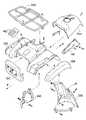
ここで、図3はフロントフェンダ135まわりの構成例を示している。図において、フロントフェンダ135にはフロントセンタフェンダ137、マッドガード138、マッドフラップ139、インナマッドフラップ140、サイドカバー141、リッド142等の部材が結合する。また、フロントフェンダ135の後部には燃料タンクカバー131aが結合するとともに、必要に応じてフロントキャリヤ143が装着される。
【0020】
また、図4はリヤフェンダ136まわりの構成例を示している。図において、リヤフェンダ136にはマッドガード144、フロントマッドガード145等の部材が結合する。また、リヤフェンダ136の上部にはシート130が配置されるとともに、必要に応じてリヤキャリヤ146が装着される。
【0021】
本発明の変速機構の冷却構造では、図5(A)にも示されるように車体フレーム101の前上部とフロントフェンダ135の間に合成樹脂製のインダクションボックス10が設けられる。このインダクションボックス10とベルト式変速装置125の前部に開口する吸気口11との間が、ゴム製のコネクタパイプ12を介して導入ダクト13で接続される。導入ダクト13は、アッパダクト14とメインダクト15からなり、両者は固定バンド16によって相互に結合される。なお、吸気口11およびコネクタパイプ12相互間、およびコネクタパイプ12およびメインダクト15相互間もそれぞれ固定バンド17,18によって結合される。
【0022】
インダクションボックス10は、アッパボックス10aとロアボックス10bとが気密に嵌合されて箱状をなしている。ロアボックス10bがボルト/ナット19等の複数の締結手段により車体フレーム101の前頭部あるいはフロントアッパパイプ102に締結固定されることで、インダクションボックス10全体が車体フレーム101の前頭部に位置決め固定され、車幅方向で略中央部に配置される。
【0023】
インダクションボックス10(アッパボックス10a)の上面部には、フロントフェンダ135の下面に近接して開口するように冷却用空気吸入口20が設けられる。空気吸入口20は横長に形成され、その外側周囲を囲むように遮蔽板21a,21bが立設されている。アッパボックス10aの内側には、空気吸入口20の周囲を囲むようにガイド筒体22が一体形成されている。
【0024】
車体フレーム101の最前部上部は、たとえばフロントアッパパイプ102を湾曲させて丸みを持たせることにより前下がり部102aが形成される。この前下がり部102a上にインダクションボックス10を設置することで、略前下がりに傾斜するインダクションボックス10の下面前部にはチャンバ部10cが形成される。チャンバ部10cの上方には上述した空気吸入口20が配置されるとともに、その最深部にはドレイン23が設けられる。
【0025】
フロントフェンダ135には上方に膨出する形状のリッド142が被着し、このリッド142には冷却用空気取入口142a(図1)が形成されている。インダクションボックス10の空気吸入口20の周囲を囲む遮蔽板21a,21bは、リッド142の内側に突出し、空気取入口142aから空気吸入口20へと空気が吸入されるようになっている。
【0026】
図5(A)においてまた、インダクションボックス10の下面後部にはダクト連結口24が開設されており、このダクト連結口24にアッパダクト14が気密に嵌合する。アッパダクト14の大部分はインダクションボックス10内部に突入し、後方に湾曲している。アッパダクト14の開口部14aはインダクションボックス10内で車幅方向で略中央に、かつ空気吸入口20から離間するとともにインダクションボックスの下面(底面)よりも高位置に配置される。
【0027】
図1に示されるように導入ダクト13は、熱交換器133と冷却ファン134との間を通り、冷却ファン134の下方を通って後方に延び、ベルト式変速装置125の吸気口11(図5(A))に接続されるようにレイアウトされる。
【0028】
ここで、図6はベルト式変速装置125の構成例を示している。前述したようにエンジンユニット123において、エンジン124はベルト式変速装置125を含むトランスミッションケースと一体に構成される。ベルト式変速装置125を収納するベルトケース147はエンジン124の一方側(この例では右側)に偏倚して配置され、その内部に前後に駆動プーリ148および従動プーリ149が配置される。駆動プーリ148は支軸150のまわりに、また従動プーリ149は支軸151のまわりにそれぞれ回転する。これらのプーリ148,149の間にベルト152が張架され、ベルト152を介して駆動プーリ148の回転力が従動プーリ149へ伝達される。駆動プーリ148には冷却ファン153が一体形成されている。
【0029】
駆動プーリ148は遠心クラッチ154を介して、エンジン124のクランクシャフト155と断接可能に連結する。なお、クランクシャフト155にはバランサ軸156aを介してバランサ156が連結する。従動プーリ149は変速ギヤユニット157と連結し、変速ギヤユニット157と連結するプロペラシャフト機構127のプロペラ軸127aが後輪122と連結している。
【0030】
駆動プーリ148においてエンジン回転数に応じて、可動フェイス148aが支軸150に沿って移動し(矢印A)、ベルト152に対する挟持幅が広狭変化することで、ベルト152の装架半径を大小変化させる。この変化に対応して、従動プーリ149の可動フェイス149aが支軸151に沿って移動し(矢印B)、これによりエンジン回転数を無段に変速することができる。
【0031】
ここで、導入ダクト13は吸気口11に接続されるが、この吸気口11にて遠心クラッチ154と駆動プーリ148との間でベルトケース147に連通する。導入ダクト13の連通部分における吸気口11の内側には、吸入空気に対するガイド部材25が付設され、ガイド部材25によって駆動プーリ148の冷却ファン153に空気を導くようになっている。
【0032】
また、後述する排風ダクト28のベルトケース147側の開口部(排気口26)は、その車幅外側内壁面が、最大減速比のときの従動プーリ149側の可動フェイス149a背面に略合致して配設される。なお、図6において、従動プーリ149の可動フェイス149aが図中、左側に移動するほど減速比は小さくなり、このときエンジン回転数としては低くなる。すなわち、エンジンの回転数が高くなる最大減速比の運転状態においては、ベルトケース内の温度上昇が顕著になる。よって、最大減速比のときの従動プーリ149側の可動フェイス149aの背面を排気口26の車幅外側内壁面に略合致させることで、冷却空気の排風効率を高くすることができる。
【0033】
図5(B)に示されるようにベルト式変速装置125の後部に開口する排気口26には、ゴム製のコネクタパイプ27を介して排風ダクト28が接続される。なお、排気口26は、前述した車幅外側内壁面が最大減速比における可動フェイス149aの背面に沿って配設される一方で、その開口中心線Lが最小減速比における可動フェイス149aの背面に沿って配設される(図6)。排気口26およびコネクタパイプ27相互間、およびコネクタパイプ27および排風ダクト28相互間はそれぞれ固定バンド29,30によって結合される。
【0034】
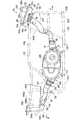
排風ダクト28は、排気口26から後斜め上方に延びた後、後輪122の車軸の上方付近で急角度に上方へ屈曲し、さらにシート130の後端の直下付近で車体左側に向きを変える(図7参照)。排風ダクト28の末端には外部に開放される空気排出口28aが開口する。ここで、図4に示したようにリヤフェンダ136の略中央部には、シート130の下方に位置するように凹陥部136aが形成されている。排風ダクト28は、図7にも示されるように凹陥部136aの後部壁136bの後側まで延設され、該後部壁136bに沿うかたちで配置される。
【0035】
排風ダクト28の略中間部には、この部分を車体フレーム101に対して位置決めする位置決め手段が一体に形成されている。この位置決め手段として、たとえば図5あるいは図7に示されるように嵌合フック31、当接部32および係合部33を含んでいる。
【0036】
嵌合フック31は、車体フレーム101の後部で車幅方向に配置されたブリッジ部115の外径面上に載置されて係合し、排風ダクト28の前後方向および下方への動きを規制する。当接部32は、嵌合フック31の右側後部近傍に位置し車体フレーム101の右側のリヤロアパイプ105の内側面に当接して、排風ダクト28の右方への動きを規制する。係合部33は、当接部32の反対側に位置し、シート130の下方に位置するリヤフェンダ136の凹陥部136aの底面近傍に係合して、排風ダクト28の上方および左方への動きを規制する。
【0037】
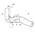
本発明では特に、図8(A)のように排風ダクト28を後面視で略逆「U」字状に形成し、排風ダクト28からの排風が少なくともリヤフェンダ136に直接当たらないように空気排出口28a(開口部)を設ける。この実施形態では、排風ダクト28の空気排出口28aをダクト本体に指向させる、すなわち図8(A)に示されるように略逆「U」字の一方の内側に空気排出口28aを開口させるとともに、空気排出口28aからの排風が他方の内側(斜線部)に当たるようにしている。
【0038】
上記構成において、つぎに本発明の作用を説明する。
エンジンユニット123が作動すると、ベルト式変速装置125の内部の駆動プーリ148に回転一体に設けられたファン153が回転して、導入ダクト13側に負圧がかかる。これにより外気が冷却空気としてフロントフェンダ135の空気取入口142aから、インダクションボックス10の冷却空気吸入口20を経てインダクションボックス10内に吸入される。そして、この冷却空気が導入ダクト13とコネクタパイプ12を経てベルト式変速装置125の内部に吸入される。
【0039】
冷却空気はベルト式変速装置125の内部で駆動プーリ148、従動プーリ149、ベルト152等の各部材を冷却した後、コネクタパイプ27と排風ダクト28を通り、冷却空気排出口28aから外部に排出される。なお、鞍乗型4輪車100の前進走行時には前方から吹く走行風がエアインテーク内に押し込まれるため、ベルト式変速装置125に供給される冷却空気の量が増加して冷却効率が向上する。
【0040】
特に本発明では、導入ダクト13をフロントフェンダ135の下面に近接した位置まで持ち上げ、そこにインダクションボックス10内でアッパダクト14の開口部14aを設ける。このように導入ダクト13を開口させることで、冷却空気と一緒に水あるいは泥等を吸い込まないようにできる。また、車幅方向の中央部で導入ダクト13を開口させることで、走行時に前輪121が巻き上げる水、泥砂あるいは塵挨等の異物が侵入するのを有効に防止することができる。
【0041】
さらに、アッパダクト14の開口部14aをインダクションボックス10内に配設するとともに、インダクションボックス10の冷却空気吸入口20をフロントフェンダ135の下面近傍に開口させることで、インダクションボックス10に吸入される空気が水や泥を含み難くする。この場合、アッパダクト14の開口部14aをインダクションボックス10の底面から上方に離間した位置で開口させるため、ベルトケース147に導入される冷却空気に、水や泥が含まれないようにする。
【0042】
このような目的で配設される導入ダクト13は、前述のように車両側面視(図1)において熱交換器133と冷却ファン134との間を通り、冷却ファン134の下方を通って後方に延び、ベルト式変速装置125に接続される。かかる長尺物の導入ダクト13は、車体フレーム101に沿うかたちで配置される構成となっている。
【0043】
つぎに、ベルトケース147内において吸気口11から吸入された冷却空気は駆動プーリ148、従動プーリ149およびベルト152等の各部材を冷却する際、導入ダクト13は遠心クラッチ154と駆動プーリ148の間に連通しているので、エンジン124に近い側のベルトケース147の内壁面も冷却することができ、ベルトケース147内部の温度上昇を抑制することができる。また、ガイド部材25を設けることで、冷却空気を効率よくファン153に導き、ベルトケース147内で円滑に流通させ、各部材を効率よく冷却することができる。
【0044】
また特に排気口26ではその開口中心線L(図6)が、最小減速比のときの従動プーリ149側の可動フェイス149aの背面に沿って配設されるため、高速走行により大量に取り入れられた冷却空気の排風抜けを確保することができる。そして、従動プーリ149の動きに合わせて空気を排出することができるとともに、排気口26の車幅外側内壁面が最大減速比における可動フェイス149a背面に沿って配設されるため、低速走行により冷却空気が少ないエンジン高回転時にも排風ダクト28の開口面積をさらに大きく確保して排風抜けを向上させることができる。
【0045】
なお、本発明のベルト式変速装置125では上流側(クランクシャフト155側)に遠心クラッチ154を配置しているので、高速走行状態から急制動で停車した場合でも駆動プーリ148を最大減速比に戻すことができる。これにより使用性、取扱性に優れた車両を実現することができる。
【0046】
排風ダクト28は、排気口26からシート130の後端の直下付近まで持ち上げ、車幅方向の中央部で空気排出口28aを開口させる。走行時に後輪122が巻き上げる水、泥砂あるいは塵挨等の異物が侵入するのを有効に防止することができる。特にリヤフェンダ136の略中央部に位置する凹陥部136aの後部壁136bの後側まで回り込ませて大気開放しており、異物が侵入し難い構成となっている。
【0047】
さらに排風ダクト28を略逆U字状に形成し(図8(A))、空気排出口28aをダクト本体に指向させることで、排風ダクト28からの排風がリヤフェンダ136に直接当たらないようにする。これにより排気ダクト28からの熱でリヤフェンダ136等が熱変形するのを有効に防止することができる。
【0048】
つぎに、本発明による変速機構の冷却構造の第2の実施形態を説明する。
この実施形態において基本構成は、第1の実施形態と実質的に同様であり、共通部分についての説明は省略する。第2の実施形態では排風ダクト28からの排風がリヤフェンダ136に直接当たらないようにするが、この場合図9に示されるように排風ダクト28の開口部28aをリヤフェンダ136側に指向させ、開口部28aを覆うように薄鉄板でなるプレート34を付設する。
【0049】
図10および図11にも示すように略逆「U」字状に形成した排風ダクト28は、第1の実施形態の場合と同様にリヤフェンダ136の凹陥部136aの後部壁136bの後側まで延設され、該後部壁136bに沿うかたちで配置される。排風ダクト28の末端の前面部(後部壁136bに対向する側)に開口部28aを開口させる。この例ではプレート34はその上部でビス35によって排風ダクト28に固定される。プレート34は開口部28aの開口縁部に沿って適度な隙間を形成しながら、排風ダクト28に付設される。
【0050】
排風ダクト28の開口部28aからは、図11の矢印のように横方向に排風され、リヤフェンダ136に直接当たることはない。これにより排気ダクト28からの熱でリヤフェンダ136等が熱変形するのを有効に防止することができる上、開口部28aを覆うようにプレート34を設けているため、水、泥等の異物が侵入するのをさらに有効に防止することができる。
【0051】
以上、本発明を種々の実施形態とともに説明したが、本発明はこれらの実施形態にのみ限定されるものではなく、本発明の範囲内で変更等が可能である。
たとえば上記実施形態で説明した排風ダクト28の開口部28a等の具体的形状等は図示例のもののみに限定されず、すなわち矩形の他に多角形、円形もしくは丸みをおびた形状等、必要に応じて適宜変更可能である。
また、上記実施形態では4輪バギー車の例で説明したが、3輪バギー車に対しても、またこの種のエンジンを搭載する他の車両に対して有効に適用可能であり、上記実施形態と同様な作用効果を得ることができる。
【0052】
【発明の効果】
以上説明したように本発明によれば、この種の冷却構造において導入ダクトの開口部をフロントフェンダの下面に近接配置することで、水や泥等の侵入を防ぐことができるるとともに、排風ダクトの開口部を、排風がリヤフェンダに直接当たらないように設けることで、リヤフェンダの熱変形を防止することができる。これにより高い防水性を確保するとともに、熱対策に優れた効果を発揮する上、構成が簡素であるため実質的にコストがかからない等の利点を有している。
【図面の簡単な説明】
【図1】本発明の実施形態における冷却構造を有する車両の全体構成例を示す図である。
【図2】本発明の実施形態における車両の全体構成例を示す上面図である。
【図3】本発明の実施形態におけるフロントフェンダまわりの分解斜視図である。
【図4】本発明の実施形態におけるリヤフェンダまわりの分解斜視図である。
【図5】本発明の実施形態における導入ダクトおよび排風ダクトまわりを示す側面図である。
【図6】本発明の実施形態におけるベルト式変速装置の構成例を示す図である。
【図7】本発明の実施形態における導入ダクトの上面図である。
【図8】本発明の実施形態における導入ダクトの後面視図および側面視図である。
【図9】本発明の第2の実施形態における導入ダクトおよび排風ダクトまわりを示す側面図である。
【図10】本発明の第2の実施形態における排風ダクトの上面図である。
【図11】本発明の第2の実施形態における排風ダクトの部分斜視図である。
【符号の説明】
10 インダクションボックス
11 吸気口
12 コネクタパイプ
13 導入ダクト
20 冷却用空気吸入口
22 ガイド筒体
24 ダクト連結口
26 排気口
27 コネクタパイプ
28 排風ダクト
31 嵌合フック
32 当接部
100 鞍乗型4輪車
101 車体フレーム
121 前輪
122 後輪
123 エンジンユニット
125 ベルト式変速装置
130 シート
131 燃料タンク
133 熱交換器
134 冷却ファン
135 フロントフェンダ
136 リヤフェンダ[0001]
BACKGROUND OF THE INVENTION
The present invention relates to a cooling structure for a transmission in particular in a straddle-type rough terrain vehicle (ATV) called a buggy vehicle or the like.
[0002]
[Prior art]
This type of vehicle has excellent running performance and high maneuverability, not only on-road, but also particularly in severe driving conditions such as off-road or waterfront. The basic configuration is, for example, that there are four wheels on the front and rear of the body frame, the engine is mounted on the body frame, and the fuel tank and seat are mounted on the top.
[0003]
If a belt is used instead of a chain as a power transmission mechanism for transmitting engine output to the wheels, the temperature in the belt case increases due to frictional heat, and the durability of the belt decreases. Therefore, the cooling effect on the belt is enhanced by positively taking in the driving wind when the vehicle is running into the belt case and discharging the cooled air from the belt case.
[0004]
For example, in the cooling structure for a belt-type transmission described in Japanese Patent Application Laid-Open No. 10-110813, the exhaust port is connected to the lower space of the vehicle seat via a flexible exhaust duct and faces the engine side positioned in front of the exhaust. It is configured to discharge. Alternatively, in the power transmission device described in Japanese Patent Laid-Open No. 11-11171, the exhaust duct is arranged and configured to improve the cooling performance of the transmission.
[0005]
[Problems to be solved by the invention]
However, in the conventional cooling structure and the like as described above, the exhaust duct is opened at a high position of the vehicle from the viewpoint of waterproofness, that is, the opening of the exhaust duct is disposed at a close position such as the rear fender. In this case, the rear fender or the like is often made of a resin material having particularly low heat resistance, and the rear fender or the like is thermally deformed by heat from the exhaust duct as it is, and melts in an extreme case.
[0006]
SUMMARY OF THE INVENTION The present invention has been made in view of the above circumstances, and an object of the present invention is to provide a cooling mechanism for a transmission mechanism that ensures high waterproofness and exhibits an effect excellent in measures against heat.
[0007]
[Means for Solving the Problems]
In the cooling mechanism for a speed change mechanism according to the present invention, a speed change mechanism for shifting the driving force of the crankshaft transmitted via the clutch to a desired speed change ratio is biased to one side in the vehicle width direction, and the speed change mechanism is accommodated. A cooling structure for a speed change mechanism in a vehicle comprising an introduction duct for introducing cooling air into a belt case and an exhaust duct for discharging air from the belt case, wherein the introduction duct is a box at a substantially central position in the vehicle width direction. One end is opened in the induction box of the mold, and the air intake port of the induction box is opened at a position close to the lower surface of the front fender, while the exhaust duct extends to the rear of the rear fender disposed below the seat. After that, rear view is omittedReverse The exhaust duct is formed in a U-shape and the exhaust duct is opened in such a form that the exhaust air does not directly hit the rear fender.
[0008]
In the cooling structure for a speed change mechanism according to the present invention, the opening of the exhaust duct is directed to the duct body.
[0009]
In the cooling structure for a speed change mechanism according to the present invention, the opening of the exhaust duct is directed toward the rear fender, and a plate is attached so as to cover the opening.
[0010]
Further, in the cooling structure of the speed change mechanism according to the present invention, the introduction duct communicates with the belt case between the clutch and the drive pulley, and a cooling air guide member is provided in the vicinity of the belt case communication portion to thereby drive the drive. The exhaust duct is configured to guide the cooling air toward the cooling fan that rotates integrally with the pulley, while the exhaust duct is movable on the driven pulley side when the inner wall in the vehicle width direction of the opening on the belt case side has the maximum reduction ratio. It is arranged along the back of the face.
[0011]
According to the present invention, the cooling air can be positively introduced into the belt case by providing the introduction duct and the exhaust duct before and after the speed change mechanism. In that case, by arranging the opening on the introduction side and the opening on the exhaust side in the center of the vehicle width, it is separated from the wheels and the like, thereby reliably preventing water, mud, etc. from entering the opening. Can do.
[0012]
In particular, by arranging the opening of the introduction duct close to the lower surface of the front fender, it is possible to prevent water, mud, and the like from entering when cooling air is introduced.
Further, by providing the opening of the exhaust duct so that the exhaust air does not directly hit the rear fender, it is possible to prevent the rear fender from being thermally deformed.
[0013]
DETAILED DESCRIPTION OF THE INVENTION
Hereinafter, preferred embodiments of a cooling structure for a speed change mechanism according to the present invention will be described with reference to the drawings.
The cooling structure according to the present invention can be effectively applied to a speed change mechanism in a straddle-type four-wheel vehicle or the like. In this embodiment, for example, as shown in FIG.
[0014]
In FIG. 1, the overall configuration of a saddle-ride type four-
[0015]
A pair of left and right
[0016]
A
[0017]
A straddle-
[0018]
A
[0019]
Here, FIG. 3 shows a configuration example around the
[0020]
FIG. 4 shows a configuration example around the
[0021]
In the cooling structure for the speed change mechanism of the present invention, an
[0022]
The
[0023]
A cooling
[0024]
A front lowering portion 102a is formed in the uppermost front upper portion of the
[0025]
A
[0026]
In FIG. 5A, a
[0027]
As shown in FIG. 1, the
[0028]
Here, FIG. 6 shows a configuration example of the belt-
[0029]
The
[0030]
In the
[0031]
Here, the
[0032]
Further, an opening (exhaust port 26) on the
[0033]
As shown in FIG. 5B, an
[0034]
The
[0035]
Positioning means for positioning this portion with respect to the
[0036]
The
[0037]
In the present invention, in particular, as shown in FIG. 8A, the
[0038]
Next, the operation of the present invention in the above configuration will be described.
When the
[0039]
The cooling air cools the
[0040]
In particular, in the present invention, the
[0041]
Further, the
[0042]
As described above, the
[0043]
Next, when the cooling air sucked from the
[0044]
Further, particularly at the
[0045]
In the belt-
[0046]
The
[0047]
Furthermore, the
[0048]
Next, a second embodiment of the cooling structure for the speed change mechanism according to the present invention will be described.
In this embodiment, the basic configuration is substantially the same as that of the first embodiment, and a description of common parts is omitted. In the second embodiment, the exhaust air from the
[0049]
As shown in FIGS. 10 and 11, the
[0050]
From the
[0051]
As mentioned above, although this invention was demonstrated with various embodiment, this invention is not limited only to these embodiment, A change etc. are possible within the scope of the present invention.
For example, the specific shape or the like of the
In the above embodiment, an example of a four-wheel buggy vehicle has been described. However, the present invention can be effectively applied to a three-wheel buggy vehicle and other vehicles equipped with this type of engine. The same effect can be obtained.
[0052]
【The invention's effect】
As described above, according to the present invention, in the cooling structure of this type, the opening of the introduction duct is disposed close to the lower surface of the front fender, so that intrusion of water, mud, and the like can be prevented, and exhaust air can be discharged. By providing the opening of the duct so that the exhausted air does not directly hit the rear fender, thermal deformation of the rear fender can be prevented. As a result, high waterproofness is ensured, an effect excellent in heat countermeasures is exhibited, and since the configuration is simple, there are advantages such as substantially no cost.
[Brief description of the drawings]
FIG. 1 is a diagram showing an example of the overall configuration of a vehicle having a cooling structure in an embodiment of the present invention.
FIG. 2 is a top view showing an example of the overall configuration of the vehicle in the embodiment of the present invention.
FIG. 3 is an exploded perspective view around a front fender in the embodiment of the present invention.
FIG. 4 is an exploded perspective view around the rear fender in the embodiment of the present invention.
FIG. 5 is a side view showing the vicinity of the introduction duct and the exhaust duct in the embodiment of the present invention.
FIG. 6 is a diagram illustrating a configuration example of a belt-type transmission according to an embodiment of the present invention.
FIG. 7 is a top view of the introduction duct in the embodiment of the present invention.
FIGS. 8A and 8B are a rear view and a side view of the introduction duct according to the embodiment of the present invention. FIGS.
FIG. 9 is a side view showing the periphery of the introduction duct and the exhaust duct in the second embodiment of the present invention.
FIG. 10 is a top view of an air exhaust duct according to a second embodiment of the present invention.
FIG. 11 is a partial perspective view of an air exhaust duct according to a second embodiment of the present invention.
[Explanation of symbols]
10 induction box
11 Inlet
12 Connector pipe
13 Introduction duct
20 Cooling air inlet
22 Guide cylinder
24 Duct connection port
26 Exhaust port
27 Connector pipe
28 Exhaust duct
31 Mating hook
32 Contact part
100 saddle riding type four-wheeled vehicle
101 body frame
121 Front wheel
122 Rear wheel
123 Engine unit
125 belt-type transmission
130 seats
131 Fuel tank
133 heat exchanger
134 Cooling fan
135 Front fender
136 Rear fender
Claims (4)
Translated fromJapanese該変速機構を収納するベルトケースに冷却空気を導入する導入ダクトと、前記ベルトケースから空気を排出する排風ダクトとを備えた車両における変速機構の冷却構造であって、
前記導入ダクトは車幅方向略中央の箱型のインダクションボックス内に一端を開口させ、該インダクションボックスの空気取入口がフロントフェンダ下面に近接した位置で開口される一方、
前記排風ダクトはシート下方に配設されたリヤフェンダの後方まで延設したのち、後面視略逆U字状に形成し、かつ排風が前記リヤフェンダに直接当たらないような形態で前記排風ダクトを開口させたことを特徴とする変速機構の冷却構造。A transmission mechanism that shifts the driving force of the crankshaft transmitted through the clutch to a desired transmission ratio is biased to one side in the vehicle width direction;
A cooling structure for a speed change mechanism in a vehicle comprising an introduction duct for introducing cooling air into a belt case that houses the speed change mechanism, and an exhaust duct for discharging air from the belt case,
The introduction duct has one end opened in a box-shaped induction box at a substantially central position in the vehicle width direction, and the air intake port of the induction box is opened at a position close to the lower surface of the front fender,
The wind exhaust duct After extending to the rear of the rear fender disposed on the sheet downward to form a rear view substantiallyinverted U-shape, and the exhaust duct in such a form that the exhaust air does not hit directly the rear fender A cooling structure for a speed change mechanism, characterized in that an opening is opened.
前記排風ダクトは、前記ベルトケース側開口部の車幅方向外側内壁が、最大減速比のときの従動プーリ側可動フェイス背面に沿って配設されることを特徴とする請求項1〜3のいずれか1項に記載の変速機構の冷却構造。The introduction duct communicates with the belt case between the clutch and the driving pulley, and a cooling air guide member is provided in the vicinity of the belt case communicating portion, and cooling air is directed toward a cooling fan that rotates integrally with the driving pulley. While configured to guide,
4. The exhaust duct according to claim 1, wherein an inner wall in the vehicle width direction of the opening on the belt case side is disposed along a back surface of the movable face on the driven pulley side at the maximum reduction ratio. The cooling structure for the speed change mechanism according to any one of the preceding claims.
Priority Applications (2)
| Application Number | Priority Date | Filing Date | Title |
|---|---|---|---|
| JP2001280033AJP4010127B2 (en) | 2001-09-14 | 2001-09-14 | Transmission mechanism cooling structure |
| US10/242,728US6820708B2 (en) | 2001-09-14 | 2002-09-13 | Cooling system for a transmission mechanism |
Applications Claiming Priority (1)
| Application Number | Priority Date | Filing Date | Title |
|---|---|---|---|
| JP2001280033AJP4010127B2 (en) | 2001-09-14 | 2001-09-14 | Transmission mechanism cooling structure |
Publications (2)
| Publication Number | Publication Date |
|---|---|
| JP2003090417A JP2003090417A (en) | 2003-03-28 |
| JP4010127B2true JP4010127B2 (en) | 2007-11-21 |
Family
ID=19104107
Family Applications (1)
| Application Number | Title | Priority Date | Filing Date |
|---|---|---|---|
| JP2001280033AExpired - LifetimeJP4010127B2 (en) | 2001-09-14 | 2001-09-14 | Transmission mechanism cooling structure |
Country Status (2)
| Country | Link |
|---|---|
| US (1) | US6820708B2 (en) |
| JP (1) | JP4010127B2 (en) |
Families Citing this family (67)
| Publication number | Priority date | Publication date | Assignee | Title |
|---|---|---|---|---|
| JP2003056679A (en)* | 2001-08-10 | 2003-02-26 | Yamaha Motor Co Ltd | Drive belt cooling structure for small vehicle |
| US6959934B2 (en)* | 2002-05-15 | 2005-11-01 | Bombardier Recreational Products Inc. | Air intake system for straddle-type all terrain vehicle |
| US7059438B1 (en)* | 2002-08-01 | 2006-06-13 | Sheets Wilbert J | ATV with an improved transmission and air intake |
| US20040140140A1 (en)* | 2003-01-17 | 2004-07-22 | Etienne Guay | Three-wheeled vehicle having an oil cooler assembly |
| US7231996B2 (en)* | 2003-02-17 | 2007-06-19 | Honda Motor Co., Ltd. | Front end components for a saddle-type vehicle |
| US6938676B2 (en)* | 2003-12-18 | 2005-09-06 | Kwang Yang Motor Co., Ltd. | Cooling structure for a continuous variation transmission system of an all-terrain vehicle |
| EP1559594B1 (en)* | 2004-01-30 | 2010-08-25 | Honda Motor Co., Ltd. | Drive shaft protector for a saddle ride type all-terrain vehicle |
| JP4526828B2 (en)* | 2004-02-06 | 2010-08-18 | 本田技研工業株式会社 | Saddle-ride type automobile |
| CA2496491C (en)* | 2004-02-13 | 2009-07-21 | Honda Motor Co., Ltd. | Vehicle body frame structure for all-terrain vehicle |
| JP4121975B2 (en)* | 2004-03-31 | 2008-07-23 | ジヤトコ株式会社 | Belt type continuously variable transmission |
| JP4506320B2 (en)* | 2004-07-15 | 2010-07-21 | スズキ株式会社 | Rear structure of rough terrain vehicle |
| JP4520341B2 (en)* | 2005-03-18 | 2010-08-04 | 本田技研工業株式会社 | Rough terrain vehicle equipped with electric power steering device |
| JP2007038736A (en)* | 2005-08-01 | 2007-02-15 | Yamaha Motor Co Ltd | Riding type vehicle |
| JP2007062715A (en)* | 2005-08-01 | 2007-03-15 | Yamaha Motor Co Ltd | Saddle riding type vehicle |
| US7562739B2 (en)* | 2006-03-16 | 2009-07-21 | Kwang Yang Motor Co., Ltd. | Cooling structure for a continuous variation transmission system of an all-terrain vehicle |
| EP1835203B1 (en)* | 2006-03-17 | 2009-09-30 | Kwang Yang Motor Co., Ltd. | Cooling mechanism for belt-based speed-change system of engine |
| WO2007146976A1 (en)* | 2006-06-14 | 2007-12-21 | Vectrix Corporation | Electric vehicle with air cooling system |
| US8827028B2 (en)* | 2006-07-28 | 2014-09-09 | Polaris Industries Inc. | Side-by-side ATV |
| US7819220B2 (en) | 2006-07-28 | 2010-10-26 | Polaris Industries Inc. | Side-by-side ATV |
| JP4894401B2 (en)* | 2006-08-09 | 2012-03-14 | スズキ株式会社 | Saddle-type rough terrain vehicle |
| JP2008063977A (en)* | 2006-09-05 | 2008-03-21 | Yamaha Motor Co Ltd | Motorcycle |
| JP4853213B2 (en)* | 2006-10-04 | 2012-01-11 | スズキ株式会社 | Saddle-type rough terrain vehicle |
| DE602007004795D1 (en)* | 2006-11-29 | 2010-04-01 | Yamaha Motor Co Ltd | motorcycle |
| US8596398B2 (en) | 2007-05-16 | 2013-12-03 | Polaris Industries Inc. | All terrain vehicle |
| US8392047B2 (en)* | 2007-06-04 | 2013-03-05 | Zf Friedrichshafen Ag | System for preventing damage to a vehicle |
| US8042869B2 (en) | 2007-07-13 | 2011-10-25 | Kids Ii, Inc. | Child seat liner |
| JP2009047246A (en)* | 2007-08-20 | 2009-03-05 | Yamaha Motor Co Ltd | Saddle-riding vehicle |
| CN101430001B (en)* | 2007-11-06 | 2013-12-04 | 光阳工业股份有限公司 | Cooling device for continuously variable transmission systems of vehicles |
| US20090309082A1 (en)* | 2008-06-11 | 2009-12-17 | Warn Industries, Inc. | Fan Cooled Winch |
| JP4887349B2 (en)* | 2008-11-28 | 2012-02-29 | 本田技研工業株式会社 | Saddle riding |
| US8381855B2 (en)* | 2009-10-23 | 2013-02-26 | Yamaha Hatsudoki Kabushiki Kaisha | All terrain vehicle |
| US8613335B2 (en) | 2010-08-03 | 2013-12-24 | Polaris Industries Inc. | Side-by-side vehicle |
| US8746719B2 (en) | 2010-08-03 | 2014-06-10 | Polaris Industries Inc. | Side-by-side vehicle |
| US9669703B2 (en)* | 2010-08-31 | 2017-06-06 | Toyota Jidosha Kabushiki Kaisha | Vehicle |
| JP2012051505A (en)* | 2010-09-02 | 2012-03-15 | Kubota Corp | Working vehicle |
| US8834307B2 (en)* | 2011-10-06 | 2014-09-16 | Kawasaki Jukogyo Kabushiki Kaisha | Belt type continuously variable transmission |
| US8911312B2 (en)* | 2011-10-06 | 2014-12-16 | Kawasaki Jukogyo Kabushiki Kaisha | Belt type continuously variable transmission |
| US8596406B2 (en)* | 2011-10-07 | 2013-12-03 | Kawasaki Jukogyo Kabushiki Kaisha | Utility vehicle |
| US8556015B2 (en) | 2011-10-07 | 2013-10-15 | Kawasaki Jukogyo Kabushiki Kaisha | Utility vehicle |
| TWM438407U (en)* | 2012-05-15 | 2012-10-01 | Kwang Yang Motor Co | Cooling air intake device of vehicle |
| TWI488759B (en)* | 2012-07-31 | 2015-06-21 | Kwang Yang Motor Co | Stepless speed change device |
| US9009993B2 (en)* | 2012-09-21 | 2015-04-21 | Harnischfeger Technologies, Inc. | Internal venting system for industrial machines |
| US9511761B2 (en) | 2012-10-19 | 2016-12-06 | Kubota Corporation | Hybrid vehicle |
| US10648554B2 (en) | 2014-09-02 | 2020-05-12 | Polaris Industries Inc. | Continuously variable transmission |
| US10300786B2 (en) | 2014-12-19 | 2019-05-28 | Polaris Industries Inc. | Utility vehicle |
| MX2017014403A (en) | 2015-05-15 | 2018-04-11 | Polaris Inc | UTILITY VEHICLE. |
| USD787985S1 (en) | 2015-06-24 | 2017-05-30 | Polaris Industries Inc. | All-terrain vehicle |
| US9649928B2 (en) | 2015-06-25 | 2017-05-16 | Polaris Industries Inc. | All-terrain vehicle |
| JP6512967B2 (en)* | 2015-07-02 | 2019-05-15 | 株式会社クボタ | Work vehicle |
| JP6416073B2 (en)* | 2015-09-29 | 2018-10-31 | 株式会社クボタ | Passenger work vehicle |
| US9884647B2 (en) | 2015-12-10 | 2018-02-06 | Polaris Industries Inc. | Utility vehicle |
| US10197149B2 (en)* | 2016-03-23 | 2019-02-05 | Kawasaki Jukogyo Kabushiki Kaisha | V-belt type continuously variable transmission |
| RU2735192C2 (en) | 2016-04-28 | 2020-10-28 | Бомбардье Рекриэйшенел Продактс Инк. | Air intake system for an off-road vehicle |
| CA3021945A1 (en)* | 2016-04-28 | 2017-11-02 | Bombardier Recreational Products Inc. | Cooling system for a turbocharger and nearby components |
| US10697532B2 (en)* | 2016-12-22 | 2020-06-30 | Polaris Industries Inc. | Housing for a transmission |
| US11173808B2 (en) | 2016-12-22 | 2021-11-16 | Polaris Industies Inc. | Vehicle |
| US10663053B2 (en) | 2017-12-15 | 2020-05-26 | Deere & Company | Continuously variable transmission air intake assembly |
| TWM566154U (en)* | 2018-03-15 | 2018-09-01 | 光陽工業股份有限公司 | Cooling air airbox structure of stepless transmission system of engine |
| WO2019182951A1 (en) | 2018-03-19 | 2019-09-26 | Polaris Industries Inc. | Electronic cvt with friction clutch |
| WO2019183051A1 (en) | 2018-03-19 | 2019-09-26 | Polaris Industries Inc. | Continuously variable transmission |
| US10946736B2 (en) | 2018-06-05 | 2021-03-16 | Polaris Industries Inc. | All-terrain vehicle |
| US10655574B2 (en)* | 2018-09-14 | 2020-05-19 | Kawasaki Jukogyo Kabushiki Kaisha | Side-by-side vehicle |
| MX2021012802A (en) | 2019-04-30 | 2021-11-12 | Polaris Inc | VEHICLE. |
| US11691674B2 (en) | 2020-05-15 | 2023-07-04 | Polaris Industries Inc. | Off-road vehicle |
| US12187127B2 (en) | 2020-05-15 | 2025-01-07 | Polaris Industries Inc. | Off-road vehicle |
| CA3156559A1 (en) | 2021-05-05 | 2022-11-05 | Polaris Industries Inc. | Exhaust assembly for a utility vehicle |
| MX2023006716A (en) | 2022-06-13 | 2023-12-14 | Polaris Inc | POWER TRAIN FOR UTILITY VEHICLE. |
Family Cites Families (21)
| Publication number | Priority date | Publication date | Assignee | Title |
|---|---|---|---|---|
| JPS60128930U (en)* | 1984-02-08 | 1985-08-29 | 本田技研工業株式会社 | Vehicle exhaust pipe device |
| JPS60252083A (en)* | 1984-05-28 | 1985-12-12 | 本田技研工業株式会社 | Air intake device in car |
| JPS6181817A (en)* | 1984-09-03 | 1986-04-25 | Honda Motor Co Ltd | Vehicle intake system |
| US4678054A (en)* | 1984-12-26 | 1987-07-07 | Honda Giken Kogyo Kabushiki Kaisha | Body frames |
| JPH0825498B2 (en)* | 1985-01-28 | 1996-03-13 | ヤマハ発動機株式会社 | Saddle-type four-wheeled vehicle for running on rough terrain |
| US4697665A (en)* | 1985-06-18 | 1987-10-06 | Polaris Industries, Inc. | Recreational vehicle with air cooled transmission |
| JP2539212B2 (en)* | 1987-02-20 | 1996-10-02 | ヤマハ発動機株式会社 | Vaporizer for snowmobiles Anti-icing device |
| US5012883A (en)* | 1988-03-20 | 1991-05-07 | Honda Giken Kogyo Kabushiki Kaisha | Air duct device for a motorcycle |
| JPH04237692A (en)* | 1991-01-16 | 1992-08-26 | Yamaha Motor Co Ltd | Engine cooling device of snow mobile |
| JP3358876B2 (en)* | 1994-07-12 | 2002-12-24 | 本田技研工業株式会社 | Saddle-type vehicle |
| JP3373942B2 (en)* | 1994-07-27 | 2003-02-04 | 本田技研工業株式会社 | Exhaust silencer |
| IT240677Y1 (en)* | 1996-05-21 | 2001-04-02 | Ducati Motorcycles S P A | DEVICE TO MODIFY THE HEIGHT FROM THE GROUND OF A SILENCER EXHAUST OF A MOTORCYCLE |
| US5738781A (en)* | 1996-08-19 | 1998-04-14 | Carlson; Terumi | Household waste water treatment and recycling system |
| JP2909027B2 (en) | 1996-10-08 | 1999-06-23 | 川崎重工業株式会社 | Cooling structure of vehicle belt type transmission |
| JPH1111171A (en) | 1997-04-28 | 1999-01-19 | Yamaha Motor Co Ltd | Power transmission of engine |
| US6269899B1 (en)* | 1997-04-28 | 2001-08-07 | Yamaha Hatsudoki Kabushiki Kaisha | Transmission for offroad vehicle |
| US6454040B1 (en)* | 1998-04-13 | 2002-09-24 | Yamaha Hatsudoki Kabushiki Kaisha | Transmission and cooling arrangement for all terrain vehicle |
| JP2000233786A (en)* | 1999-02-17 | 2000-08-29 | Yamaha Motor Co Ltd | Structure of transmitting driving force to right and left wheels on vehicle |
| US6622806B1 (en)* | 1999-04-27 | 2003-09-23 | Yamaha Hatsudoki Kabushiki Kaisha | Air inlet for ATV |
| JP2001280127A (en)* | 2000-03-30 | 2001-10-10 | Honda Motor Co Ltd | Exhaust pipe system mounting structure for vehicles |
| US6591935B1 (en)* | 2000-07-17 | 2003-07-15 | Gary L. Petley | ATV stealth exhaust system |
- 2001
- 2001-09-14JPJP2001280033Apatent/JP4010127B2/ennot_activeExpired - Lifetime
- 2002
- 2002-09-13USUS10/242,728patent/US6820708B2/ennot_activeExpired - Lifetime
Also Published As
| Publication number | Publication date |
|---|---|
| US6820708B2 (en) | 2004-11-23 |
| US20030066696A1 (en) | 2003-04-10 |
| JP2003090417A (en) | 2003-03-28 |
Similar Documents
| Publication | Publication Date | Title |
|---|---|---|
| JP4010127B2 (en) | Transmission mechanism cooling structure | |
| JP2002274468A (en) | Saddle riding type four-wheel vehicle | |
| US9453573B2 (en) | Continuously variable transmission assembly for a vehicle | |
| JP4586438B2 (en) | Front structure of rough terrain vehicle | |
| US10655574B2 (en) | Side-by-side vehicle | |
| EP1143166A2 (en) | V belt type transmission | |
| US7975792B2 (en) | Straddle type vehicle | |
| JP2009047246A (en) | Saddle-riding vehicle | |
| JP5484835B2 (en) | Air intake structure for saddle-ride type vehicles | |
| JPH059317B2 (en) | ||
| JP4802727B2 (en) | Rough terrain vehicle | |
| JP3562279B2 (en) | Automatic belt cooling system for scooter type vehicle | |
| JP2009226986A (en) | Cooling duct structure for motorcycle transmission | |
| JP4134596B2 (en) | Cooling structure of belt type automatic transmission for scooter type motorcycle | |
| JPS6189187A (en) | Belt type variable speed gear of car for uneven ground travelling | |
| EP1553331B1 (en) | Cooling structure for a continuous variation transmission system of an all-terrain vehicle | |
| JP4281290B2 (en) | Cooling structure for belt-type transmission | |
| JPS6317695Y2 (en) | ||
| JP3890898B2 (en) | Secondary air supply device for scooter type motorcycle | |
| JPH0722391Y2 (en) | Saddle-type four-wheeled vehicle | |
| JPS6216530Y2 (en) | ||
| JP2843570B2 (en) | Belt type transmission for vehicles on uneven terrain | |
| CN101746455B (en) | Striding type vehicle | |
| JP2892651B2 (en) | Belt type transmission for vehicles | |
| JP2522937B2 (en) | V-belt transmission cooling device for vehicles |
Legal Events
| Date | Code | Title | Description |
|---|---|---|---|
| A621 | Written request for application examination | Free format text:JAPANESE INTERMEDIATE CODE: A621 Effective date:20040910 | |
| A977 | Report on retrieval | Free format text:JAPANESE INTERMEDIATE CODE: A971007 Effective date:20070122 | |
| A131 | Notification of reasons for refusal | Free format text:JAPANESE INTERMEDIATE CODE: A131 Effective date:20070123 | |
| A521 | Request for written amendment filed | Free format text:JAPANESE INTERMEDIATE CODE: A523 Effective date:20070216 | |
| TRDD | Decision of grant or rejection written | ||
| A01 | Written decision to grant a patent or to grant a registration (utility model) | Free format text:JAPANESE INTERMEDIATE CODE: A01 Effective date:20070814 | |
| A61 | First payment of annual fees (during grant procedure) | Free format text:JAPANESE INTERMEDIATE CODE: A61 Effective date:20070827 | |
| R151 | Written notification of patent or utility model registration | Ref document number:4010127 Country of ref document:JP Free format text:JAPANESE INTERMEDIATE CODE: R151 | |
| FPAY | Renewal fee payment (event date is renewal date of database) | Free format text:PAYMENT UNTIL: 20100914 Year of fee payment:3 | |
| FPAY | Renewal fee payment (event date is renewal date of database) | Free format text:PAYMENT UNTIL: 20110914 Year of fee payment:4 | |
| FPAY | Renewal fee payment (event date is renewal date of database) | Free format text:PAYMENT UNTIL: 20110914 Year of fee payment:4 | |
| FPAY | Renewal fee payment (event date is renewal date of database) | Free format text:PAYMENT UNTIL: 20120914 Year of fee payment:5 | |
| FPAY | Renewal fee payment (event date is renewal date of database) | Free format text:PAYMENT UNTIL: 20120914 Year of fee payment:5 | |
| FPAY | Renewal fee payment (event date is renewal date of database) | Free format text:PAYMENT UNTIL: 20130914 Year of fee payment:6 | |
| FPAY | Renewal fee payment (event date is renewal date of database) | Free format text:PAYMENT UNTIL: 20130914 Year of fee payment:6 | |
| FPAY | Renewal fee payment (event date is renewal date of database) | Free format text:PAYMENT UNTIL: 20140914 Year of fee payment:7 | |
| EXPY | Cancellation because of completion of term |