JP4005613B2 - Screwless spinal fusion graft - Google Patents
Screwless spinal fusion graftDownload PDFInfo
- Publication number
- JP4005613B2 JP4005613B2JP2005296242AJP2005296242AJP4005613B2JP 4005613 B2JP4005613 B2JP 4005613B2JP 2005296242 AJP2005296242 AJP 2005296242AJP 2005296242 AJP2005296242 AJP 2005296242AJP 4005613 B2JP4005613 B2JP 4005613B2
- Authority
- JP
- Japan
- Prior art keywords
- implant
- spinal fusion
- bone
- graft
- adjacent
- Prior art date
- Legal status (The legal status is an assumption and is not a legal conclusion. Google has not performed a legal analysis and makes no representation as to the accuracy of the status listed.)
- Expired - Fee Related
Links
- 230000004927fusionEffects0.000titleclaimsabstractdescription63
- 239000007943implantSubstances0.000claimsabstractdescription98
- 210000000988bone and boneAnatomy0.000claimsabstractdescription42
- 238000003780insertionMethods0.000claimsabstractdescription22
- 230000037431insertionEffects0.000claimsabstractdescription22
- 239000000463materialSubstances0.000claimsabstractdescription21
- 239000000126substanceSubstances0.000claimsdescription11
- 230000001737promoting effectEffects0.000claimsdescription8
- 108090000623proteins and genesProteins0.000claimsdescription5
- 102000004169proteins and genesHuman genes0.000claimsdescription5
- 229910052588hydroxylapatiteInorganic materials0.000claimsdescription4
- 238000007788rougheningMethods0.000claimsdescription4
- 230000000921morphogenic effectEffects0.000claimsdescription3
- -1hydroxyapatite compoundChemical class0.000claimsdescription2
- XYJRXVWERLGGKC-UHFFFAOYSA-Dpentacalcium;hydroxide;triphosphateChemical compound[OH-].[Ca+2].[Ca+2].[Ca+2].[Ca+2].[Ca+2].[O-]P([O-])([O-])=O.[O-]P([O-])([O-])=O.[O-]P([O-])([O-])=OXYJRXVWERLGGKC-UHFFFAOYSA-D0.000claimsdescription2
- 102000007350Bone Morphogenetic ProteinsHuman genes0.000claims2
- 108010007726Bone Morphogenetic ProteinsProteins0.000claims2
- 229940112869bone morphogenetic proteinDrugs0.000claims2
- 238000005452bendingMethods0.000claims1
- 208000007623LordosisDiseases0.000abstractdescription7
- 238000007499fusion processingMethods0.000abstractdescription7
- 238000002513implantationMethods0.000abstractdescription3
- 238000004873anchoringMethods0.000description3
- 230000008468bone growthEffects0.000description2
- 230000001788irregularEffects0.000description2
- 210000004705lumbosacral regionAnatomy0.000description2
- 238000000034methodMethods0.000description2
- RTAQQCXQSZGOHL-UHFFFAOYSA-NTitaniumChemical compound[Ti]RTAQQCXQSZGOHL-UHFFFAOYSA-N0.000description1
- WAIPAZQMEIHHTJ-UHFFFAOYSA-N[Cr].[Co]Chemical class[Cr].[Co]WAIPAZQMEIHHTJ-UHFFFAOYSA-N0.000description1
- 230000009471actionEffects0.000description1
- 229910045601alloyInorganic materials0.000description1
- 239000000956alloySubstances0.000description1
- 239000000919ceramicSubstances0.000description1
- 210000003679cervix uteriAnatomy0.000description1
- 230000008859changeEffects0.000description1
- 239000011248coating agentSubstances0.000description1
- 238000000576coating methodMethods0.000description1
- 230000000295complement effectEffects0.000description1
- 230000008878couplingEffects0.000description1
- 238000010168coupling processMethods0.000description1
- 238000005859coupling reactionMethods0.000description1
- 239000000835fiberSubstances0.000description1
- 238000009499grossingMethods0.000description1
- 230000014759maintenance of locationEffects0.000description1
- 229910052751metalInorganic materials0.000description1
- 239000002184metalSubstances0.000description1
- 239000004033plasticSubstances0.000description1
- 229920003023plasticPolymers0.000description1
- 239000011148porous materialSubstances0.000description1
- 238000011084recoveryMethods0.000description1
- 238000002271resectionMethods0.000description1
- 239000010935stainless steelSubstances0.000description1
- 229910001220stainless steelInorganic materials0.000description1
- 229910052719titaniumInorganic materials0.000description1
- 239000010936titaniumSubstances0.000description1
Images


Classifications
- A—HUMAN NECESSITIES
- A61—MEDICAL OR VETERINARY SCIENCE; HYGIENE
- A61B—DIAGNOSIS; SURGERY; IDENTIFICATION
- A61B17/00—Surgical instruments, devices or methods
- A61B17/56—Surgical instruments or methods for treatment of bones or joints; Devices specially adapted therefor
- A61B17/58—Surgical instruments or methods for treatment of bones or joints; Devices specially adapted therefor for osteosynthesis, e.g. bone plates, screws or setting implements
- A61B17/68—Internal fixation devices, including fasteners and spinal fixators, even if a part thereof projects from the skin
- A61B17/84—Fasteners therefor or fasteners being internal fixation devices
- A—HUMAN NECESSITIES
- A61—MEDICAL OR VETERINARY SCIENCE; HYGIENE
- A61F—FILTERS IMPLANTABLE INTO BLOOD VESSELS; PROSTHESES; DEVICES PROVIDING PATENCY TO, OR PREVENTING COLLAPSING OF, TUBULAR STRUCTURES OF THE BODY, e.g. STENTS; ORTHOPAEDIC, NURSING OR CONTRACEPTIVE DEVICES; FOMENTATION; TREATMENT OR PROTECTION OF EYES OR EARS; BANDAGES, DRESSINGS OR ABSORBENT PADS; FIRST-AID KITS
- A61F2/00—Filters implantable into blood vessels; Prostheses, i.e. artificial substitutes or replacements for parts of the body; Appliances for connecting them with the body; Devices providing patency to, or preventing collapsing of, tubular structures of the body, e.g. stents
- A61F2/02—Prostheses implantable into the body
- A61F2/30—Joints
- A61F2/30767—Special external or bone-contacting surface, e.g. coating for improving bone ingrowth
- A61F2/30771—Special external or bone-contacting surface, e.g. coating for improving bone ingrowth applied in original prostheses, e.g. holes or grooves
- A—HUMAN NECESSITIES
- A61—MEDICAL OR VETERINARY SCIENCE; HYGIENE
- A61B—DIAGNOSIS; SURGERY; IDENTIFICATION
- A61B17/00—Surgical instruments, devices or methods
- A61B17/02—Surgical instruments, devices or methods for holding wounds open, e.g. retractors; Tractors
- A61B17/025—Joint distractors
- A—HUMAN NECESSITIES
- A61—MEDICAL OR VETERINARY SCIENCE; HYGIENE
- A61B—DIAGNOSIS; SURGERY; IDENTIFICATION
- A61B17/00—Surgical instruments, devices or methods
- A61B17/16—Instruments for performing osteoclasis; Drills or chisels for bones; Trepans
- A61B17/1662—Instruments for performing osteoclasis; Drills or chisels for bones; Trepans for particular parts of the body
- A61B17/1671—Instruments for performing osteoclasis; Drills or chisels for bones; Trepans for particular parts of the body for the spine
- A—HUMAN NECESSITIES
- A61—MEDICAL OR VETERINARY SCIENCE; HYGIENE
- A61B—DIAGNOSIS; SURGERY; IDENTIFICATION
- A61B17/00—Surgical instruments, devices or methods
- A61B17/16—Instruments for performing osteoclasis; Drills or chisels for bones; Trepans
- A61B17/17—Guides or aligning means for drills, mills, pins or wires
- A61B17/1739—Guides or aligning means for drills, mills, pins or wires specially adapted for particular parts of the body
- A61B17/1757—Guides or aligning means for drills, mills, pins or wires specially adapted for particular parts of the body for the spine
- A—HUMAN NECESSITIES
- A61—MEDICAL OR VETERINARY SCIENCE; HYGIENE
- A61F—FILTERS IMPLANTABLE INTO BLOOD VESSELS; PROSTHESES; DEVICES PROVIDING PATENCY TO, OR PREVENTING COLLAPSING OF, TUBULAR STRUCTURES OF THE BODY, e.g. STENTS; ORTHOPAEDIC, NURSING OR CONTRACEPTIVE DEVICES; FOMENTATION; TREATMENT OR PROTECTION OF EYES OR EARS; BANDAGES, DRESSINGS OR ABSORBENT PADS; FIRST-AID KITS
- A61F2/00—Filters implantable into blood vessels; Prostheses, i.e. artificial substitutes or replacements for parts of the body; Appliances for connecting them with the body; Devices providing patency to, or preventing collapsing of, tubular structures of the body, e.g. stents
- A61F2/02—Prostheses implantable into the body
- A61F2/30—Joints
- A61F2/30721—Accessories
- A61F2/30744—End caps, e.g. for closing an endoprosthetic cavity
- A—HUMAN NECESSITIES
- A61—MEDICAL OR VETERINARY SCIENCE; HYGIENE
- A61F—FILTERS IMPLANTABLE INTO BLOOD VESSELS; PROSTHESES; DEVICES PROVIDING PATENCY TO, OR PREVENTING COLLAPSING OF, TUBULAR STRUCTURES OF THE BODY, e.g. STENTS; ORTHOPAEDIC, NURSING OR CONTRACEPTIVE DEVICES; FOMENTATION; TREATMENT OR PROTECTION OF EYES OR EARS; BANDAGES, DRESSINGS OR ABSORBENT PADS; FIRST-AID KITS
- A61F2/00—Filters implantable into blood vessels; Prostheses, i.e. artificial substitutes or replacements for parts of the body; Appliances for connecting them with the body; Devices providing patency to, or preventing collapsing of, tubular structures of the body, e.g. stents
- A61F2/02—Prostheses implantable into the body
- A61F2/30—Joints
- A61F2/44—Joints for the spine, e.g. vertebrae, spinal discs
- A61F2/4455—Joints for the spine, e.g. vertebrae, spinal discs for the fusion of spinal bodies, e.g. intervertebral fusion of adjacent spinal bodies, e.g. fusion cages
- A61F2/446—Joints for the spine, e.g. vertebrae, spinal discs for the fusion of spinal bodies, e.g. intervertebral fusion of adjacent spinal bodies, e.g. fusion cages having a circular or elliptical cross-section substantially parallel to the axis of the spine, e.g. cylinders or frustocones
- A—HUMAN NECESSITIES
- A61—MEDICAL OR VETERINARY SCIENCE; HYGIENE
- A61F—FILTERS IMPLANTABLE INTO BLOOD VESSELS; PROSTHESES; DEVICES PROVIDING PATENCY TO, OR PREVENTING COLLAPSING OF, TUBULAR STRUCTURES OF THE BODY, e.g. STENTS; ORTHOPAEDIC, NURSING OR CONTRACEPTIVE DEVICES; FOMENTATION; TREATMENT OR PROTECTION OF EYES OR EARS; BANDAGES, DRESSINGS OR ABSORBENT PADS; FIRST-AID KITS
- A61F2/00—Filters implantable into blood vessels; Prostheses, i.e. artificial substitutes or replacements for parts of the body; Appliances for connecting them with the body; Devices providing patency to, or preventing collapsing of, tubular structures of the body, e.g. stents
- A61F2/02—Prostheses implantable into the body
- A61F2/30—Joints
- A61F2/46—Special tools for implanting artificial joints
- A61F2/4601—Special tools for implanting artificial joints for introducing bone substitute, for implanting bone graft implants or for compacting them in the bone cavity
- A—HUMAN NECESSITIES
- A61—MEDICAL OR VETERINARY SCIENCE; HYGIENE
- A61F—FILTERS IMPLANTABLE INTO BLOOD VESSELS; PROSTHESES; DEVICES PROVIDING PATENCY TO, OR PREVENTING COLLAPSING OF, TUBULAR STRUCTURES OF THE BODY, e.g. STENTS; ORTHOPAEDIC, NURSING OR CONTRACEPTIVE DEVICES; FOMENTATION; TREATMENT OR PROTECTION OF EYES OR EARS; BANDAGES, DRESSINGS OR ABSORBENT PADS; FIRST-AID KITS
- A61F2/00—Filters implantable into blood vessels; Prostheses, i.e. artificial substitutes or replacements for parts of the body; Appliances for connecting them with the body; Devices providing patency to, or preventing collapsing of, tubular structures of the body, e.g. stents
- A61F2/02—Prostheses implantable into the body
- A61F2/30—Joints
- A61F2/46—Special tools for implanting artificial joints
- A61F2/4603—Special tools for implanting artificial joints for insertion or extraction of endoprosthetic joints or of accessories thereof
- A61F2/4611—Special tools for implanting artificial joints for insertion or extraction of endoprosthetic joints or of accessories thereof of spinal prostheses
- A—HUMAN NECESSITIES
- A61—MEDICAL OR VETERINARY SCIENCE; HYGIENE
- A61B—DIAGNOSIS; SURGERY; IDENTIFICATION
- A61B17/00—Surgical instruments, devices or methods
- A61B17/32—Surgical cutting instruments
- A—HUMAN NECESSITIES
- A61—MEDICAL OR VETERINARY SCIENCE; HYGIENE
- A61B—DIAGNOSIS; SURGERY; IDENTIFICATION
- A61B17/00—Surgical instruments, devices or methods
- A61B17/02—Surgical instruments, devices or methods for holding wounds open, e.g. retractors; Tractors
- A61B17/025—Joint distractors
- A61B2017/0256—Joint distractors for the spine
- A—HUMAN NECESSITIES
- A61—MEDICAL OR VETERINARY SCIENCE; HYGIENE
- A61B—DIAGNOSIS; SURGERY; IDENTIFICATION
- A61B17/00—Surgical instruments, devices or methods
- A61B17/56—Surgical instruments or methods for treatment of bones or joints; Devices specially adapted therefor
- A61B17/58—Surgical instruments or methods for treatment of bones or joints; Devices specially adapted therefor for osteosynthesis, e.g. bone plates, screws or setting implements
- A61B17/88—Osteosynthesis instruments; Methods or means for implanting or extracting internal or external fixation devices
- A61B17/92—Impactors or extractors, e.g. for removing intramedullary devices
- A61B2017/922—Devices for impaction, impact element
- A—HUMAN NECESSITIES
- A61—MEDICAL OR VETERINARY SCIENCE; HYGIENE
- A61B—DIAGNOSIS; SURGERY; IDENTIFICATION
- A61B90/00—Instruments, implements or accessories specially adapted for surgery or diagnosis and not covered by any of the groups A61B1/00 - A61B50/00, e.g. for luxation treatment or for protecting wound edges
- A61B90/03—Automatic limiting or abutting means, e.g. for safety
- A61B2090/033—Abutting means, stops, e.g. abutting on tissue or skin
- A61B2090/036—Abutting means, stops, e.g. abutting on tissue or skin abutting on tissue or skin
- A—HUMAN NECESSITIES
- A61—MEDICAL OR VETERINARY SCIENCE; HYGIENE
- A61F—FILTERS IMPLANTABLE INTO BLOOD VESSELS; PROSTHESES; DEVICES PROVIDING PATENCY TO, OR PREVENTING COLLAPSING OF, TUBULAR STRUCTURES OF THE BODY, e.g. STENTS; ORTHOPAEDIC, NURSING OR CONTRACEPTIVE DEVICES; FOMENTATION; TREATMENT OR PROTECTION OF EYES OR EARS; BANDAGES, DRESSINGS OR ABSORBENT PADS; FIRST-AID KITS
- A61F2/00—Filters implantable into blood vessels; Prostheses, i.e. artificial substitutes or replacements for parts of the body; Appliances for connecting them with the body; Devices providing patency to, or preventing collapsing of, tubular structures of the body, e.g. stents
- A61F2/02—Prostheses implantable into the body
- A61F2/30—Joints
- A61F2/30767—Special external or bone-contacting surface, e.g. coating for improving bone ingrowth
- A—HUMAN NECESSITIES
- A61—MEDICAL OR VETERINARY SCIENCE; HYGIENE
- A61F—FILTERS IMPLANTABLE INTO BLOOD VESSELS; PROSTHESES; DEVICES PROVIDING PATENCY TO, OR PREVENTING COLLAPSING OF, TUBULAR STRUCTURES OF THE BODY, e.g. STENTS; ORTHOPAEDIC, NURSING OR CONTRACEPTIVE DEVICES; FOMENTATION; TREATMENT OR PROTECTION OF EYES OR EARS; BANDAGES, DRESSINGS OR ABSORBENT PADS; FIRST-AID KITS
- A61F2/00—Filters implantable into blood vessels; Prostheses, i.e. artificial substitutes or replacements for parts of the body; Appliances for connecting them with the body; Devices providing patency to, or preventing collapsing of, tubular structures of the body, e.g. stents
- A61F2/02—Prostheses implantable into the body
- A61F2/30—Joints
- A61F2/44—Joints for the spine, e.g. vertebrae, spinal discs
- A61F2/442—Intervertebral or spinal discs, e.g. resilient
- A—HUMAN NECESSITIES
- A61—MEDICAL OR VETERINARY SCIENCE; HYGIENE
- A61F—FILTERS IMPLANTABLE INTO BLOOD VESSELS; PROSTHESES; DEVICES PROVIDING PATENCY TO, OR PREVENTING COLLAPSING OF, TUBULAR STRUCTURES OF THE BODY, e.g. STENTS; ORTHOPAEDIC, NURSING OR CONTRACEPTIVE DEVICES; FOMENTATION; TREATMENT OR PROTECTION OF EYES OR EARS; BANDAGES, DRESSINGS OR ABSORBENT PADS; FIRST-AID KITS
- A61F2/00—Filters implantable into blood vessels; Prostheses, i.e. artificial substitutes or replacements for parts of the body; Appliances for connecting them with the body; Devices providing patency to, or preventing collapsing of, tubular structures of the body, e.g. stents
- A61F2/02—Prostheses implantable into the body
- A61F2/30—Joints
- A61F2/46—Special tools for implanting artificial joints
- A61F2/4603—Special tools for implanting artificial joints for insertion or extraction of endoprosthetic joints or of accessories thereof
- A—HUMAN NECESSITIES
- A61—MEDICAL OR VETERINARY SCIENCE; HYGIENE
- A61F—FILTERS IMPLANTABLE INTO BLOOD VESSELS; PROSTHESES; DEVICES PROVIDING PATENCY TO, OR PREVENTING COLLAPSING OF, TUBULAR STRUCTURES OF THE BODY, e.g. STENTS; ORTHOPAEDIC, NURSING OR CONTRACEPTIVE DEVICES; FOMENTATION; TREATMENT OR PROTECTION OF EYES OR EARS; BANDAGES, DRESSINGS OR ABSORBENT PADS; FIRST-AID KITS
- A61F2/00—Filters implantable into blood vessels; Prostheses, i.e. artificial substitutes or replacements for parts of the body; Appliances for connecting them with the body; Devices providing patency to, or preventing collapsing of, tubular structures of the body, e.g. stents
- A61F2/02—Prostheses implantable into the body
- A61F2/30—Joints
- A61F2/46—Special tools for implanting artificial joints
- A61F2/4657—Measuring instruments used for implanting artificial joints
- A—HUMAN NECESSITIES
- A61—MEDICAL OR VETERINARY SCIENCE; HYGIENE
- A61F—FILTERS IMPLANTABLE INTO BLOOD VESSELS; PROSTHESES; DEVICES PROVIDING PATENCY TO, OR PREVENTING COLLAPSING OF, TUBULAR STRUCTURES OF THE BODY, e.g. STENTS; ORTHOPAEDIC, NURSING OR CONTRACEPTIVE DEVICES; FOMENTATION; TREATMENT OR PROTECTION OF EYES OR EARS; BANDAGES, DRESSINGS OR ABSORBENT PADS; FIRST-AID KITS
- A61F2/00—Filters implantable into blood vessels; Prostheses, i.e. artificial substitutes or replacements for parts of the body; Appliances for connecting them with the body; Devices providing patency to, or preventing collapsing of, tubular structures of the body, e.g. stents
- A61F2/02—Prostheses implantable into the body
- A61F2/28—Bones
- A61F2002/2835—Bone graft implants for filling a bony defect or an endoprosthesis cavity, e.g. by synthetic material or biological material
- A—HUMAN NECESSITIES
- A61—MEDICAL OR VETERINARY SCIENCE; HYGIENE
- A61F—FILTERS IMPLANTABLE INTO BLOOD VESSELS; PROSTHESES; DEVICES PROVIDING PATENCY TO, OR PREVENTING COLLAPSING OF, TUBULAR STRUCTURES OF THE BODY, e.g. STENTS; ORTHOPAEDIC, NURSING OR CONTRACEPTIVE DEVICES; FOMENTATION; TREATMENT OR PROTECTION OF EYES OR EARS; BANDAGES, DRESSINGS OR ABSORBENT PADS; FIRST-AID KITS
- A61F2/00—Filters implantable into blood vessels; Prostheses, i.e. artificial substitutes or replacements for parts of the body; Appliances for connecting them with the body; Devices providing patency to, or preventing collapsing of, tubular structures of the body, e.g. stents
- A61F2/02—Prostheses implantable into the body
- A61F2/30—Joints
- A61F2002/30001—Additional features of subject-matter classified in A61F2/28, A61F2/30 and subgroups thereof
- A61F2002/30003—Material related properties of the prosthesis or of a coating on the prosthesis
- A61F2002/3006—Properties of materials and coating materials
- A61F2002/30062—(bio)absorbable, biodegradable, bioerodable, (bio)resorbable, resorptive
- A—HUMAN NECESSITIES
- A61—MEDICAL OR VETERINARY SCIENCE; HYGIENE
- A61F—FILTERS IMPLANTABLE INTO BLOOD VESSELS; PROSTHESES; DEVICES PROVIDING PATENCY TO, OR PREVENTING COLLAPSING OF, TUBULAR STRUCTURES OF THE BODY, e.g. STENTS; ORTHOPAEDIC, NURSING OR CONTRACEPTIVE DEVICES; FOMENTATION; TREATMENT OR PROTECTION OF EYES OR EARS; BANDAGES, DRESSINGS OR ABSORBENT PADS; FIRST-AID KITS
- A61F2/00—Filters implantable into blood vessels; Prostheses, i.e. artificial substitutes or replacements for parts of the body; Appliances for connecting them with the body; Devices providing patency to, or preventing collapsing of, tubular structures of the body, e.g. stents
- A61F2/02—Prostheses implantable into the body
- A61F2/30—Joints
- A61F2002/30001—Additional features of subject-matter classified in A61F2/28, A61F2/30 and subgroups thereof
- A61F2002/30108—Shapes
- A61F2002/3011—Cross-sections or two-dimensional shapes
- A61F2002/30112—Rounded shapes, e.g. with rounded corners
- A61F2002/3013—Rounded shapes, e.g. with rounded corners figure-"8"- or hourglass-shaped
- A—HUMAN NECESSITIES
- A61—MEDICAL OR VETERINARY SCIENCE; HYGIENE
- A61F—FILTERS IMPLANTABLE INTO BLOOD VESSELS; PROSTHESES; DEVICES PROVIDING PATENCY TO, OR PREVENTING COLLAPSING OF, TUBULAR STRUCTURES OF THE BODY, e.g. STENTS; ORTHOPAEDIC, NURSING OR CONTRACEPTIVE DEVICES; FOMENTATION; TREATMENT OR PROTECTION OF EYES OR EARS; BANDAGES, DRESSINGS OR ABSORBENT PADS; FIRST-AID KITS
- A61F2/00—Filters implantable into blood vessels; Prostheses, i.e. artificial substitutes or replacements for parts of the body; Appliances for connecting them with the body; Devices providing patency to, or preventing collapsing of, tubular structures of the body, e.g. stents
- A61F2/02—Prostheses implantable into the body
- A61F2/30—Joints
- A61F2002/30001—Additional features of subject-matter classified in A61F2/28, A61F2/30 and subgroups thereof
- A61F2002/30108—Shapes
- A61F2002/3011—Cross-sections or two-dimensional shapes
- A61F2002/30112—Rounded shapes, e.g. with rounded corners
- A61F2002/30131—Rounded shapes, e.g. with rounded corners horseshoe- or crescent- or C-shaped or U-shaped
- A—HUMAN NECESSITIES
- A61—MEDICAL OR VETERINARY SCIENCE; HYGIENE
- A61F—FILTERS IMPLANTABLE INTO BLOOD VESSELS; PROSTHESES; DEVICES PROVIDING PATENCY TO, OR PREVENTING COLLAPSING OF, TUBULAR STRUCTURES OF THE BODY, e.g. STENTS; ORTHOPAEDIC, NURSING OR CONTRACEPTIVE DEVICES; FOMENTATION; TREATMENT OR PROTECTION OF EYES OR EARS; BANDAGES, DRESSINGS OR ABSORBENT PADS; FIRST-AID KITS
- A61F2/00—Filters implantable into blood vessels; Prostheses, i.e. artificial substitutes or replacements for parts of the body; Appliances for connecting them with the body; Devices providing patency to, or preventing collapsing of, tubular structures of the body, e.g. stents
- A61F2/02—Prostheses implantable into the body
- A61F2/30—Joints
- A61F2002/30001—Additional features of subject-matter classified in A61F2/28, A61F2/30 and subgroups thereof
- A61F2002/30108—Shapes
- A61F2002/3011—Cross-sections or two-dimensional shapes
- A61F2002/30138—Convex polygonal shapes
- A61F2002/30143—Convex polygonal shapes hexagonal
- A—HUMAN NECESSITIES
- A61—MEDICAL OR VETERINARY SCIENCE; HYGIENE
- A61F—FILTERS IMPLANTABLE INTO BLOOD VESSELS; PROSTHESES; DEVICES PROVIDING PATENCY TO, OR PREVENTING COLLAPSING OF, TUBULAR STRUCTURES OF THE BODY, e.g. STENTS; ORTHOPAEDIC, NURSING OR CONTRACEPTIVE DEVICES; FOMENTATION; TREATMENT OR PROTECTION OF EYES OR EARS; BANDAGES, DRESSINGS OR ABSORBENT PADS; FIRST-AID KITS
- A61F2/00—Filters implantable into blood vessels; Prostheses, i.e. artificial substitutes or replacements for parts of the body; Appliances for connecting them with the body; Devices providing patency to, or preventing collapsing of, tubular structures of the body, e.g. stents
- A61F2/02—Prostheses implantable into the body
- A61F2/30—Joints
- A61F2002/30001—Additional features of subject-matter classified in A61F2/28, A61F2/30 and subgroups thereof
- A61F2002/30108—Shapes
- A61F2002/3011—Cross-sections or two-dimensional shapes
- A61F2002/30138—Convex polygonal shapes
- A61F2002/30148—Convex polygonal shapes lozenge- or diamond-shaped
- A—HUMAN NECESSITIES
- A61—MEDICAL OR VETERINARY SCIENCE; HYGIENE
- A61F—FILTERS IMPLANTABLE INTO BLOOD VESSELS; PROSTHESES; DEVICES PROVIDING PATENCY TO, OR PREVENTING COLLAPSING OF, TUBULAR STRUCTURES OF THE BODY, e.g. STENTS; ORTHOPAEDIC, NURSING OR CONTRACEPTIVE DEVICES; FOMENTATION; TREATMENT OR PROTECTION OF EYES OR EARS; BANDAGES, DRESSINGS OR ABSORBENT PADS; FIRST-AID KITS
- A61F2/00—Filters implantable into blood vessels; Prostheses, i.e. artificial substitutes or replacements for parts of the body; Appliances for connecting them with the body; Devices providing patency to, or preventing collapsing of, tubular structures of the body, e.g. stents
- A61F2/02—Prostheses implantable into the body
- A61F2/30—Joints
- A61F2002/30001—Additional features of subject-matter classified in A61F2/28, A61F2/30 and subgroups thereof
- A61F2002/30108—Shapes
- A61F2002/30199—Three-dimensional shapes
- A61F2002/30205—Three-dimensional shapes conical
- A61F2002/3021—Three-dimensional shapes conical frustoconical
- A—HUMAN NECESSITIES
- A61—MEDICAL OR VETERINARY SCIENCE; HYGIENE
- A61F—FILTERS IMPLANTABLE INTO BLOOD VESSELS; PROSTHESES; DEVICES PROVIDING PATENCY TO, OR PREVENTING COLLAPSING OF, TUBULAR STRUCTURES OF THE BODY, e.g. STENTS; ORTHOPAEDIC, NURSING OR CONTRACEPTIVE DEVICES; FOMENTATION; TREATMENT OR PROTECTION OF EYES OR EARS; BANDAGES, DRESSINGS OR ABSORBENT PADS; FIRST-AID KITS
- A61F2/00—Filters implantable into blood vessels; Prostheses, i.e. artificial substitutes or replacements for parts of the body; Appliances for connecting them with the body; Devices providing patency to, or preventing collapsing of, tubular structures of the body, e.g. stents
- A61F2/02—Prostheses implantable into the body
- A61F2/30—Joints
- A61F2002/30001—Additional features of subject-matter classified in A61F2/28, A61F2/30 and subgroups thereof
- A61F2002/30108—Shapes
- A61F2002/30199—Three-dimensional shapes
- A61F2002/30205—Three-dimensional shapes conical
- A61F2002/30217—Three-dimensional shapes conical hollow cones, e.g. tubular-like cones
- A—HUMAN NECESSITIES
- A61—MEDICAL OR VETERINARY SCIENCE; HYGIENE
- A61F—FILTERS IMPLANTABLE INTO BLOOD VESSELS; PROSTHESES; DEVICES PROVIDING PATENCY TO, OR PREVENTING COLLAPSING OF, TUBULAR STRUCTURES OF THE BODY, e.g. STENTS; ORTHOPAEDIC, NURSING OR CONTRACEPTIVE DEVICES; FOMENTATION; TREATMENT OR PROTECTION OF EYES OR EARS; BANDAGES, DRESSINGS OR ABSORBENT PADS; FIRST-AID KITS
- A61F2/00—Filters implantable into blood vessels; Prostheses, i.e. artificial substitutes or replacements for parts of the body; Appliances for connecting them with the body; Devices providing patency to, or preventing collapsing of, tubular structures of the body, e.g. stents
- A61F2/02—Prostheses implantable into the body
- A61F2/30—Joints
- A61F2002/30001—Additional features of subject-matter classified in A61F2/28, A61F2/30 and subgroups thereof
- A61F2002/30108—Shapes
- A61F2002/30199—Three-dimensional shapes
- A61F2002/30224—Three-dimensional shapes cylindrical
- A61F2002/30235—Three-dimensional shapes cylindrical tubular, e.g. sleeves
- A—HUMAN NECESSITIES
- A61—MEDICAL OR VETERINARY SCIENCE; HYGIENE
- A61F—FILTERS IMPLANTABLE INTO BLOOD VESSELS; PROSTHESES; DEVICES PROVIDING PATENCY TO, OR PREVENTING COLLAPSING OF, TUBULAR STRUCTURES OF THE BODY, e.g. STENTS; ORTHOPAEDIC, NURSING OR CONTRACEPTIVE DEVICES; FOMENTATION; TREATMENT OR PROTECTION OF EYES OR EARS; BANDAGES, DRESSINGS OR ABSORBENT PADS; FIRST-AID KITS
- A61F2/00—Filters implantable into blood vessels; Prostheses, i.e. artificial substitutes or replacements for parts of the body; Appliances for connecting them with the body; Devices providing patency to, or preventing collapsing of, tubular structures of the body, e.g. stents
- A61F2/02—Prostheses implantable into the body
- A61F2/30—Joints
- A61F2002/30001—Additional features of subject-matter classified in A61F2/28, A61F2/30 and subgroups thereof
- A61F2002/30316—The prosthesis having different structural features at different locations within the same prosthesis; Connections between prosthetic parts; Special structural features of bone or joint prostheses not otherwise provided for
- A61F2002/30329—Connections or couplings between prosthetic parts, e.g. between modular parts; Connecting elements
- A61F2002/30405—Connections or couplings between prosthetic parts, e.g. between modular parts; Connecting elements made by screwing complementary threads machined on the parts themselves
- A—HUMAN NECESSITIES
- A61—MEDICAL OR VETERINARY SCIENCE; HYGIENE
- A61F—FILTERS IMPLANTABLE INTO BLOOD VESSELS; PROSTHESES; DEVICES PROVIDING PATENCY TO, OR PREVENTING COLLAPSING OF, TUBULAR STRUCTURES OF THE BODY, e.g. STENTS; ORTHOPAEDIC, NURSING OR CONTRACEPTIVE DEVICES; FOMENTATION; TREATMENT OR PROTECTION OF EYES OR EARS; BANDAGES, DRESSINGS OR ABSORBENT PADS; FIRST-AID KITS
- A61F2/00—Filters implantable into blood vessels; Prostheses, i.e. artificial substitutes or replacements for parts of the body; Appliances for connecting them with the body; Devices providing patency to, or preventing collapsing of, tubular structures of the body, e.g. stents
- A61F2/02—Prostheses implantable into the body
- A61F2/30—Joints
- A61F2002/30001—Additional features of subject-matter classified in A61F2/28, A61F2/30 and subgroups thereof
- A61F2002/30316—The prosthesis having different structural features at different locations within the same prosthesis; Connections between prosthetic parts; Special structural features of bone or joint prostheses not otherwise provided for
- A61F2002/30329—Connections or couplings between prosthetic parts, e.g. between modular parts; Connecting elements
- A61F2002/30426—Bayonet coupling
- A—HUMAN NECESSITIES
- A61—MEDICAL OR VETERINARY SCIENCE; HYGIENE
- A61F—FILTERS IMPLANTABLE INTO BLOOD VESSELS; PROSTHESES; DEVICES PROVIDING PATENCY TO, OR PREVENTING COLLAPSING OF, TUBULAR STRUCTURES OF THE BODY, e.g. STENTS; ORTHOPAEDIC, NURSING OR CONTRACEPTIVE DEVICES; FOMENTATION; TREATMENT OR PROTECTION OF EYES OR EARS; BANDAGES, DRESSINGS OR ABSORBENT PADS; FIRST-AID KITS
- A61F2/00—Filters implantable into blood vessels; Prostheses, i.e. artificial substitutes or replacements for parts of the body; Appliances for connecting them with the body; Devices providing patency to, or preventing collapsing of, tubular structures of the body, e.g. stents
- A61F2/02—Prostheses implantable into the body
- A61F2/30—Joints
- A61F2002/30001—Additional features of subject-matter classified in A61F2/28, A61F2/30 and subgroups thereof
- A61F2002/30316—The prosthesis having different structural features at different locations within the same prosthesis; Connections between prosthetic parts; Special structural features of bone or joint prostheses not otherwise provided for
- A61F2002/30535—Special structural features of bone or joint prostheses not otherwise provided for
- A61F2002/30593—Special structural features of bone or joint prostheses not otherwise provided for hollow
- A—HUMAN NECESSITIES
- A61—MEDICAL OR VETERINARY SCIENCE; HYGIENE
- A61F—FILTERS IMPLANTABLE INTO BLOOD VESSELS; PROSTHESES; DEVICES PROVIDING PATENCY TO, OR PREVENTING COLLAPSING OF, TUBULAR STRUCTURES OF THE BODY, e.g. STENTS; ORTHOPAEDIC, NURSING OR CONTRACEPTIVE DEVICES; FOMENTATION; TREATMENT OR PROTECTION OF EYES OR EARS; BANDAGES, DRESSINGS OR ABSORBENT PADS; FIRST-AID KITS
- A61F2/00—Filters implantable into blood vessels; Prostheses, i.e. artificial substitutes or replacements for parts of the body; Appliances for connecting them with the body; Devices providing patency to, or preventing collapsing of, tubular structures of the body, e.g. stents
- A61F2/02—Prostheses implantable into the body
- A61F2/30—Joints
- A61F2002/30001—Additional features of subject-matter classified in A61F2/28, A61F2/30 and subgroups thereof
- A61F2002/30316—The prosthesis having different structural features at different locations within the same prosthesis; Connections between prosthetic parts; Special structural features of bone or joint prostheses not otherwise provided for
- A61F2002/30535—Special structural features of bone or joint prostheses not otherwise provided for
- A61F2002/30604—Special structural features of bone or joint prostheses not otherwise provided for modular
- A—HUMAN NECESSITIES
- A61—MEDICAL OR VETERINARY SCIENCE; HYGIENE
- A61F—FILTERS IMPLANTABLE INTO BLOOD VESSELS; PROSTHESES; DEVICES PROVIDING PATENCY TO, OR PREVENTING COLLAPSING OF, TUBULAR STRUCTURES OF THE BODY, e.g. STENTS; ORTHOPAEDIC, NURSING OR CONTRACEPTIVE DEVICES; FOMENTATION; TREATMENT OR PROTECTION OF EYES OR EARS; BANDAGES, DRESSINGS OR ABSORBENT PADS; FIRST-AID KITS
- A61F2/00—Filters implantable into blood vessels; Prostheses, i.e. artificial substitutes or replacements for parts of the body; Appliances for connecting them with the body; Devices providing patency to, or preventing collapsing of, tubular structures of the body, e.g. stents
- A61F2/02—Prostheses implantable into the body
- A61F2/30—Joints
- A61F2/30767—Special external or bone-contacting surface, e.g. coating for improving bone ingrowth
- A61F2/30771—Special external or bone-contacting surface, e.g. coating for improving bone ingrowth applied in original prostheses, e.g. holes or grooves
- A61F2002/30772—Apertures or holes, e.g. of circular cross section
- A61F2002/30774—Apertures or holes, e.g. of circular cross section internally-threaded
- A—HUMAN NECESSITIES
- A61—MEDICAL OR VETERINARY SCIENCE; HYGIENE
- A61F—FILTERS IMPLANTABLE INTO BLOOD VESSELS; PROSTHESES; DEVICES PROVIDING PATENCY TO, OR PREVENTING COLLAPSING OF, TUBULAR STRUCTURES OF THE BODY, e.g. STENTS; ORTHOPAEDIC, NURSING OR CONTRACEPTIVE DEVICES; FOMENTATION; TREATMENT OR PROTECTION OF EYES OR EARS; BANDAGES, DRESSINGS OR ABSORBENT PADS; FIRST-AID KITS
- A61F2/00—Filters implantable into blood vessels; Prostheses, i.e. artificial substitutes or replacements for parts of the body; Appliances for connecting them with the body; Devices providing patency to, or preventing collapsing of, tubular structures of the body, e.g. stents
- A61F2/02—Prostheses implantable into the body
- A61F2/30—Joints
- A61F2/30767—Special external or bone-contacting surface, e.g. coating for improving bone ingrowth
- A61F2/30771—Special external or bone-contacting surface, e.g. coating for improving bone ingrowth applied in original prostheses, e.g. holes or grooves
- A61F2002/30772—Apertures or holes, e.g. of circular cross section
- A61F2002/30777—Oblong apertures
- A—HUMAN NECESSITIES
- A61—MEDICAL OR VETERINARY SCIENCE; HYGIENE
- A61F—FILTERS IMPLANTABLE INTO BLOOD VESSELS; PROSTHESES; DEVICES PROVIDING PATENCY TO, OR PREVENTING COLLAPSING OF, TUBULAR STRUCTURES OF THE BODY, e.g. STENTS; ORTHOPAEDIC, NURSING OR CONTRACEPTIVE DEVICES; FOMENTATION; TREATMENT OR PROTECTION OF EYES OR EARS; BANDAGES, DRESSINGS OR ABSORBENT PADS; FIRST-AID KITS
- A61F2/00—Filters implantable into blood vessels; Prostheses, i.e. artificial substitutes or replacements for parts of the body; Appliances for connecting them with the body; Devices providing patency to, or preventing collapsing of, tubular structures of the body, e.g. stents
- A61F2/02—Prostheses implantable into the body
- A61F2/30—Joints
- A61F2/30767—Special external or bone-contacting surface, e.g. coating for improving bone ingrowth
- A61F2/30771—Special external or bone-contacting surface, e.g. coating for improving bone ingrowth applied in original prostheses, e.g. holes or grooves
- A61F2002/30772—Apertures or holes, e.g. of circular cross section
- A61F2002/30784—Plurality of holes
- A61F2002/30785—Plurality of holes parallel
- A—HUMAN NECESSITIES
- A61—MEDICAL OR VETERINARY SCIENCE; HYGIENE
- A61F—FILTERS IMPLANTABLE INTO BLOOD VESSELS; PROSTHESES; DEVICES PROVIDING PATENCY TO, OR PREVENTING COLLAPSING OF, TUBULAR STRUCTURES OF THE BODY, e.g. STENTS; ORTHOPAEDIC, NURSING OR CONTRACEPTIVE DEVICES; FOMENTATION; TREATMENT OR PROTECTION OF EYES OR EARS; BANDAGES, DRESSINGS OR ABSORBENT PADS; FIRST-AID KITS
- A61F2/00—Filters implantable into blood vessels; Prostheses, i.e. artificial substitutes or replacements for parts of the body; Appliances for connecting them with the body; Devices providing patency to, or preventing collapsing of, tubular structures of the body, e.g. stents
- A61F2/02—Prostheses implantable into the body
- A61F2/30—Joints
- A61F2/30767—Special external or bone-contacting surface, e.g. coating for improving bone ingrowth
- A61F2/30771—Special external or bone-contacting surface, e.g. coating for improving bone ingrowth applied in original prostheses, e.g. holes or grooves
- A61F2002/30772—Apertures or holes, e.g. of circular cross section
- A61F2002/30784—Plurality of holes
- A61F2002/30787—Plurality of holes inclined obliquely with respect to each other
- A—HUMAN NECESSITIES
- A61—MEDICAL OR VETERINARY SCIENCE; HYGIENE
- A61F—FILTERS IMPLANTABLE INTO BLOOD VESSELS; PROSTHESES; DEVICES PROVIDING PATENCY TO, OR PREVENTING COLLAPSING OF, TUBULAR STRUCTURES OF THE BODY, e.g. STENTS; ORTHOPAEDIC, NURSING OR CONTRACEPTIVE DEVICES; FOMENTATION; TREATMENT OR PROTECTION OF EYES OR EARS; BANDAGES, DRESSINGS OR ABSORBENT PADS; FIRST-AID KITS
- A61F2/00—Filters implantable into blood vessels; Prostheses, i.e. artificial substitutes or replacements for parts of the body; Appliances for connecting them with the body; Devices providing patency to, or preventing collapsing of, tubular structures of the body, e.g. stents
- A61F2/02—Prostheses implantable into the body
- A61F2/30—Joints
- A61F2/30767—Special external or bone-contacting surface, e.g. coating for improving bone ingrowth
- A61F2/30771—Special external or bone-contacting surface, e.g. coating for improving bone ingrowth applied in original prostheses, e.g. holes or grooves
- A61F2002/30795—Blind bores, e.g. of circular cross-section
- A61F2002/30797—Blind bores, e.g. of circular cross-section internally-threaded
- A—HUMAN NECESSITIES
- A61—MEDICAL OR VETERINARY SCIENCE; HYGIENE
- A61F—FILTERS IMPLANTABLE INTO BLOOD VESSELS; PROSTHESES; DEVICES PROVIDING PATENCY TO, OR PREVENTING COLLAPSING OF, TUBULAR STRUCTURES OF THE BODY, e.g. STENTS; ORTHOPAEDIC, NURSING OR CONTRACEPTIVE DEVICES; FOMENTATION; TREATMENT OR PROTECTION OF EYES OR EARS; BANDAGES, DRESSINGS OR ABSORBENT PADS; FIRST-AID KITS
- A61F2/00—Filters implantable into blood vessels; Prostheses, i.e. artificial substitutes or replacements for parts of the body; Appliances for connecting them with the body; Devices providing patency to, or preventing collapsing of, tubular structures of the body, e.g. stents
- A61F2/02—Prostheses implantable into the body
- A61F2/30—Joints
- A61F2/30767—Special external or bone-contacting surface, e.g. coating for improving bone ingrowth
- A61F2/30771—Special external or bone-contacting surface, e.g. coating for improving bone ingrowth applied in original prostheses, e.g. holes or grooves
- A61F2002/30795—Blind bores, e.g. of circular cross-section
- A61F2002/30807—Plurality of blind bores
- A61F2002/30808—Plurality of blind bores parallel
- A—HUMAN NECESSITIES
- A61—MEDICAL OR VETERINARY SCIENCE; HYGIENE
- A61F—FILTERS IMPLANTABLE INTO BLOOD VESSELS; PROSTHESES; DEVICES PROVIDING PATENCY TO, OR PREVENTING COLLAPSING OF, TUBULAR STRUCTURES OF THE BODY, e.g. STENTS; ORTHOPAEDIC, NURSING OR CONTRACEPTIVE DEVICES; FOMENTATION; TREATMENT OR PROTECTION OF EYES OR EARS; BANDAGES, DRESSINGS OR ABSORBENT PADS; FIRST-AID KITS
- A61F2/00—Filters implantable into blood vessels; Prostheses, i.e. artificial substitutes or replacements for parts of the body; Appliances for connecting them with the body; Devices providing patency to, or preventing collapsing of, tubular structures of the body, e.g. stents
- A61F2/02—Prostheses implantable into the body
- A61F2/30—Joints
- A61F2/30767—Special external or bone-contacting surface, e.g. coating for improving bone ingrowth
- A61F2/30771—Special external or bone-contacting surface, e.g. coating for improving bone ingrowth applied in original prostheses, e.g. holes or grooves
- A61F2002/30795—Blind bores, e.g. of circular cross-section
- A61F2002/30807—Plurality of blind bores
- A61F2002/3081—Plurality of blind bores inclined obliquely with respect to each other
- A—HUMAN NECESSITIES
- A61—MEDICAL OR VETERINARY SCIENCE; HYGIENE
- A61F—FILTERS IMPLANTABLE INTO BLOOD VESSELS; PROSTHESES; DEVICES PROVIDING PATENCY TO, OR PREVENTING COLLAPSING OF, TUBULAR STRUCTURES OF THE BODY, e.g. STENTS; ORTHOPAEDIC, NURSING OR CONTRACEPTIVE DEVICES; FOMENTATION; TREATMENT OR PROTECTION OF EYES OR EARS; BANDAGES, DRESSINGS OR ABSORBENT PADS; FIRST-AID KITS
- A61F2/00—Filters implantable into blood vessels; Prostheses, i.e. artificial substitutes or replacements for parts of the body; Appliances for connecting them with the body; Devices providing patency to, or preventing collapsing of, tubular structures of the body, e.g. stents
- A61F2/02—Prostheses implantable into the body
- A61F2/30—Joints
- A61F2/30767—Special external or bone-contacting surface, e.g. coating for improving bone ingrowth
- A61F2/30771—Special external or bone-contacting surface, e.g. coating for improving bone ingrowth applied in original prostheses, e.g. holes or grooves
- A61F2002/30836—Special external or bone-contacting surface, e.g. coating for improving bone ingrowth applied in original prostheses, e.g. holes or grooves knurled
- A—HUMAN NECESSITIES
- A61—MEDICAL OR VETERINARY SCIENCE; HYGIENE
- A61F—FILTERS IMPLANTABLE INTO BLOOD VESSELS; PROSTHESES; DEVICES PROVIDING PATENCY TO, OR PREVENTING COLLAPSING OF, TUBULAR STRUCTURES OF THE BODY, e.g. STENTS; ORTHOPAEDIC, NURSING OR CONTRACEPTIVE DEVICES; FOMENTATION; TREATMENT OR PROTECTION OF EYES OR EARS; BANDAGES, DRESSINGS OR ABSORBENT PADS; FIRST-AID KITS
- A61F2/00—Filters implantable into blood vessels; Prostheses, i.e. artificial substitutes or replacements for parts of the body; Appliances for connecting them with the body; Devices providing patency to, or preventing collapsing of, tubular structures of the body, e.g. stents
- A61F2/02—Prostheses implantable into the body
- A61F2/30—Joints
- A61F2/30767—Special external or bone-contacting surface, e.g. coating for improving bone ingrowth
- A61F2/30771—Special external or bone-contacting surface, e.g. coating for improving bone ingrowth applied in original prostheses, e.g. holes or grooves
- A61F2002/3085—Special external or bone-contacting surface, e.g. coating for improving bone ingrowth applied in original prostheses, e.g. holes or grooves with a threaded, e.g. self-tapping, bone-engaging surface, e.g. external surface
- A—HUMAN NECESSITIES
- A61—MEDICAL OR VETERINARY SCIENCE; HYGIENE
- A61F—FILTERS IMPLANTABLE INTO BLOOD VESSELS; PROSTHESES; DEVICES PROVIDING PATENCY TO, OR PREVENTING COLLAPSING OF, TUBULAR STRUCTURES OF THE BODY, e.g. STENTS; ORTHOPAEDIC, NURSING OR CONTRACEPTIVE DEVICES; FOMENTATION; TREATMENT OR PROTECTION OF EYES OR EARS; BANDAGES, DRESSINGS OR ABSORBENT PADS; FIRST-AID KITS
- A61F2/00—Filters implantable into blood vessels; Prostheses, i.e. artificial substitutes or replacements for parts of the body; Appliances for connecting them with the body; Devices providing patency to, or preventing collapsing of, tubular structures of the body, e.g. stents
- A61F2/02—Prostheses implantable into the body
- A61F2/30—Joints
- A61F2/30767—Special external or bone-contacting surface, e.g. coating for improving bone ingrowth
- A61F2/30771—Special external or bone-contacting surface, e.g. coating for improving bone ingrowth applied in original prostheses, e.g. holes or grooves
- A61F2002/30878—Special external or bone-contacting surface, e.g. coating for improving bone ingrowth applied in original prostheses, e.g. holes or grooves with non-sharp protrusions, for instance contacting the bone for anchoring, e.g. keels, pegs, pins, posts, shanks, stems, struts
- A61F2002/30879—Ribs
- A—HUMAN NECESSITIES
- A61—MEDICAL OR VETERINARY SCIENCE; HYGIENE
- A61F—FILTERS IMPLANTABLE INTO BLOOD VESSELS; PROSTHESES; DEVICES PROVIDING PATENCY TO, OR PREVENTING COLLAPSING OF, TUBULAR STRUCTURES OF THE BODY, e.g. STENTS; ORTHOPAEDIC, NURSING OR CONTRACEPTIVE DEVICES; FOMENTATION; TREATMENT OR PROTECTION OF EYES OR EARS; BANDAGES, DRESSINGS OR ABSORBENT PADS; FIRST-AID KITS
- A61F2/00—Filters implantable into blood vessels; Prostheses, i.e. artificial substitutes or replacements for parts of the body; Appliances for connecting them with the body; Devices providing patency to, or preventing collapsing of, tubular structures of the body, e.g. stents
- A61F2/02—Prostheses implantable into the body
- A61F2/30—Joints
- A61F2/30767—Special external or bone-contacting surface, e.g. coating for improving bone ingrowth
- A61F2/30771—Special external or bone-contacting surface, e.g. coating for improving bone ingrowth applied in original prostheses, e.g. holes or grooves
- A61F2002/30878—Special external or bone-contacting surface, e.g. coating for improving bone ingrowth applied in original prostheses, e.g. holes or grooves with non-sharp protrusions, for instance contacting the bone for anchoring, e.g. keels, pegs, pins, posts, shanks, stems, struts
- A61F2002/30891—Plurality of protrusions
- A61F2002/30892—Plurality of protrusions parallel
- A—HUMAN NECESSITIES
- A61—MEDICAL OR VETERINARY SCIENCE; HYGIENE
- A61F—FILTERS IMPLANTABLE INTO BLOOD VESSELS; PROSTHESES; DEVICES PROVIDING PATENCY TO, OR PREVENTING COLLAPSING OF, TUBULAR STRUCTURES OF THE BODY, e.g. STENTS; ORTHOPAEDIC, NURSING OR CONTRACEPTIVE DEVICES; FOMENTATION; TREATMENT OR PROTECTION OF EYES OR EARS; BANDAGES, DRESSINGS OR ABSORBENT PADS; FIRST-AID KITS
- A61F2/00—Filters implantable into blood vessels; Prostheses, i.e. artificial substitutes or replacements for parts of the body; Appliances for connecting them with the body; Devices providing patency to, or preventing collapsing of, tubular structures of the body, e.g. stents
- A61F2/02—Prostheses implantable into the body
- A61F2/30—Joints
- A61F2/30767—Special external or bone-contacting surface, e.g. coating for improving bone ingrowth
- A61F2/30771—Special external or bone-contacting surface, e.g. coating for improving bone ingrowth applied in original prostheses, e.g. holes or grooves
- A61F2002/30878—Special external or bone-contacting surface, e.g. coating for improving bone ingrowth applied in original prostheses, e.g. holes or grooves with non-sharp protrusions, for instance contacting the bone for anchoring, e.g. keels, pegs, pins, posts, shanks, stems, struts
- A61F2002/30891—Plurality of protrusions
- A61F2002/30894—Plurality of protrusions inclined obliquely with respect to each other
- A—HUMAN NECESSITIES
- A61—MEDICAL OR VETERINARY SCIENCE; HYGIENE
- A61F—FILTERS IMPLANTABLE INTO BLOOD VESSELS; PROSTHESES; DEVICES PROVIDING PATENCY TO, OR PREVENTING COLLAPSING OF, TUBULAR STRUCTURES OF THE BODY, e.g. STENTS; ORTHOPAEDIC, NURSING OR CONTRACEPTIVE DEVICES; FOMENTATION; TREATMENT OR PROTECTION OF EYES OR EARS; BANDAGES, DRESSINGS OR ABSORBENT PADS; FIRST-AID KITS
- A61F2/00—Filters implantable into blood vessels; Prostheses, i.e. artificial substitutes or replacements for parts of the body; Appliances for connecting them with the body; Devices providing patency to, or preventing collapsing of, tubular structures of the body, e.g. stents
- A61F2/02—Prostheses implantable into the body
- A61F2/30—Joints
- A61F2/30767—Special external or bone-contacting surface, e.g. coating for improving bone ingrowth
- A61F2/30771—Special external or bone-contacting surface, e.g. coating for improving bone ingrowth applied in original prostheses, e.g. holes or grooves
- A61F2002/30904—Special external or bone-contacting surface, e.g. coating for improving bone ingrowth applied in original prostheses, e.g. holes or grooves serrated profile, i.e. saw-toothed
- A—HUMAN NECESSITIES
- A61—MEDICAL OR VETERINARY SCIENCE; HYGIENE
- A61F—FILTERS IMPLANTABLE INTO BLOOD VESSELS; PROSTHESES; DEVICES PROVIDING PATENCY TO, OR PREVENTING COLLAPSING OF, TUBULAR STRUCTURES OF THE BODY, e.g. STENTS; ORTHOPAEDIC, NURSING OR CONTRACEPTIVE DEVICES; FOMENTATION; TREATMENT OR PROTECTION OF EYES OR EARS; BANDAGES, DRESSINGS OR ABSORBENT PADS; FIRST-AID KITS
- A61F2/00—Filters implantable into blood vessels; Prostheses, i.e. artificial substitutes or replacements for parts of the body; Appliances for connecting them with the body; Devices providing patency to, or preventing collapsing of, tubular structures of the body, e.g. stents
- A61F2/02—Prostheses implantable into the body
- A61F2/30—Joints
- A61F2/30767—Special external or bone-contacting surface, e.g. coating for improving bone ingrowth
- A61F2002/30906—Special external or bone-contacting surface, e.g. coating for improving bone ingrowth shot- sand- or grit-blasted
- A—HUMAN NECESSITIES
- A61—MEDICAL OR VETERINARY SCIENCE; HYGIENE
- A61F—FILTERS IMPLANTABLE INTO BLOOD VESSELS; PROSTHESES; DEVICES PROVIDING PATENCY TO, OR PREVENTING COLLAPSING OF, TUBULAR STRUCTURES OF THE BODY, e.g. STENTS; ORTHOPAEDIC, NURSING OR CONTRACEPTIVE DEVICES; FOMENTATION; TREATMENT OR PROTECTION OF EYES OR EARS; BANDAGES, DRESSINGS OR ABSORBENT PADS; FIRST-AID KITS
- A61F2/00—Filters implantable into blood vessels; Prostheses, i.e. artificial substitutes or replacements for parts of the body; Appliances for connecting them with the body; Devices providing patency to, or preventing collapsing of, tubular structures of the body, e.g. stents
- A61F2/02—Prostheses implantable into the body
- A61F2/30—Joints
- A61F2/30767—Special external or bone-contacting surface, e.g. coating for improving bone ingrowth
- A61F2/30907—Nets or sleeves applied to surface of prostheses or in cement
- A61F2002/30909—Nets
- A—HUMAN NECESSITIES
- A61—MEDICAL OR VETERINARY SCIENCE; HYGIENE
- A61F—FILTERS IMPLANTABLE INTO BLOOD VESSELS; PROSTHESES; DEVICES PROVIDING PATENCY TO, OR PREVENTING COLLAPSING OF, TUBULAR STRUCTURES OF THE BODY, e.g. STENTS; ORTHOPAEDIC, NURSING OR CONTRACEPTIVE DEVICES; FOMENTATION; TREATMENT OR PROTECTION OF EYES OR EARS; BANDAGES, DRESSINGS OR ABSORBENT PADS; FIRST-AID KITS
- A61F2/00—Filters implantable into blood vessels; Prostheses, i.e. artificial substitutes or replacements for parts of the body; Appliances for connecting them with the body; Devices providing patency to, or preventing collapsing of, tubular structures of the body, e.g. stents
- A61F2/02—Prostheses implantable into the body
- A61F2/30—Joints
- A61F2/44—Joints for the spine, e.g. vertebrae, spinal discs
- A61F2002/448—Joints for the spine, e.g. vertebrae, spinal discs comprising multiple adjacent spinal implants within the same intervertebral space or within the same vertebra, e.g. comprising two adjacent spinal implants
- A—HUMAN NECESSITIES
- A61—MEDICAL OR VETERINARY SCIENCE; HYGIENE
- A61F—FILTERS IMPLANTABLE INTO BLOOD VESSELS; PROSTHESES; DEVICES PROVIDING PATENCY TO, OR PREVENTING COLLAPSING OF, TUBULAR STRUCTURES OF THE BODY, e.g. STENTS; ORTHOPAEDIC, NURSING OR CONTRACEPTIVE DEVICES; FOMENTATION; TREATMENT OR PROTECTION OF EYES OR EARS; BANDAGES, DRESSINGS OR ABSORBENT PADS; FIRST-AID KITS
- A61F2/00—Filters implantable into blood vessels; Prostheses, i.e. artificial substitutes or replacements for parts of the body; Appliances for connecting them with the body; Devices providing patency to, or preventing collapsing of, tubular structures of the body, e.g. stents
- A61F2/02—Prostheses implantable into the body
- A61F2/30—Joints
- A61F2/44—Joints for the spine, e.g. vertebrae, spinal discs
- A61F2002/449—Joints for the spine, e.g. vertebrae, spinal discs comprising multiple spinal implants located in different intervertebral spaces or in different vertebrae
- A—HUMAN NECESSITIES
- A61—MEDICAL OR VETERINARY SCIENCE; HYGIENE
- A61F—FILTERS IMPLANTABLE INTO BLOOD VESSELS; PROSTHESES; DEVICES PROVIDING PATENCY TO, OR PREVENTING COLLAPSING OF, TUBULAR STRUCTURES OF THE BODY, e.g. STENTS; ORTHOPAEDIC, NURSING OR CONTRACEPTIVE DEVICES; FOMENTATION; TREATMENT OR PROTECTION OF EYES OR EARS; BANDAGES, DRESSINGS OR ABSORBENT PADS; FIRST-AID KITS
- A61F2/00—Filters implantable into blood vessels; Prostheses, i.e. artificial substitutes or replacements for parts of the body; Appliances for connecting them with the body; Devices providing patency to, or preventing collapsing of, tubular structures of the body, e.g. stents
- A61F2/02—Prostheses implantable into the body
- A61F2/30—Joints
- A61F2/46—Special tools for implanting artificial joints
- A61F2/4603—Special tools for implanting artificial joints for insertion or extraction of endoprosthetic joints or of accessories thereof
- A61F2002/4619—Special tools for implanting artificial joints for insertion or extraction of endoprosthetic joints or of accessories thereof for extraction
- A—HUMAN NECESSITIES
- A61—MEDICAL OR VETERINARY SCIENCE; HYGIENE
- A61F—FILTERS IMPLANTABLE INTO BLOOD VESSELS; PROSTHESES; DEVICES PROVIDING PATENCY TO, OR PREVENTING COLLAPSING OF, TUBULAR STRUCTURES OF THE BODY, e.g. STENTS; ORTHOPAEDIC, NURSING OR CONTRACEPTIVE DEVICES; FOMENTATION; TREATMENT OR PROTECTION OF EYES OR EARS; BANDAGES, DRESSINGS OR ABSORBENT PADS; FIRST-AID KITS
- A61F2/00—Filters implantable into blood vessels; Prostheses, i.e. artificial substitutes or replacements for parts of the body; Appliances for connecting them with the body; Devices providing patency to, or preventing collapsing of, tubular structures of the body, e.g. stents
- A61F2/02—Prostheses implantable into the body
- A61F2/30—Joints
- A61F2/46—Special tools for implanting artificial joints
- A61F2/4603—Special tools for implanting artificial joints for insertion or extraction of endoprosthetic joints or of accessories thereof
- A61F2002/4629—Special tools for implanting artificial joints for insertion or extraction of endoprosthetic joints or of accessories thereof connected to the endoprosthesis or implant via a threaded connection
- A—HUMAN NECESSITIES
- A61—MEDICAL OR VETERINARY SCIENCE; HYGIENE
- A61F—FILTERS IMPLANTABLE INTO BLOOD VESSELS; PROSTHESES; DEVICES PROVIDING PATENCY TO, OR PREVENTING COLLAPSING OF, TUBULAR STRUCTURES OF THE BODY, e.g. STENTS; ORTHOPAEDIC, NURSING OR CONTRACEPTIVE DEVICES; FOMENTATION; TREATMENT OR PROTECTION OF EYES OR EARS; BANDAGES, DRESSINGS OR ABSORBENT PADS; FIRST-AID KITS
- A61F2/00—Filters implantable into blood vessels; Prostheses, i.e. artificial substitutes or replacements for parts of the body; Appliances for connecting them with the body; Devices providing patency to, or preventing collapsing of, tubular structures of the body, e.g. stents
- A61F2/02—Prostheses implantable into the body
- A61F2/30—Joints
- A61F2/46—Special tools for implanting artificial joints
- A61F2/4644—Preparation of bone graft, bone plugs or bone dowels, e.g. grinding or milling bone material
- A61F2002/4649—Bone graft or bone dowel harvest sites
- A—HUMAN NECESSITIES
- A61—MEDICAL OR VETERINARY SCIENCE; HYGIENE
- A61F—FILTERS IMPLANTABLE INTO BLOOD VESSELS; PROSTHESES; DEVICES PROVIDING PATENCY TO, OR PREVENTING COLLAPSING OF, TUBULAR STRUCTURES OF THE BODY, e.g. STENTS; ORTHOPAEDIC, NURSING OR CONTRACEPTIVE DEVICES; FOMENTATION; TREATMENT OR PROTECTION OF EYES OR EARS; BANDAGES, DRESSINGS OR ABSORBENT PADS; FIRST-AID KITS
- A61F2/00—Filters implantable into blood vessels; Prostheses, i.e. artificial substitutes or replacements for parts of the body; Appliances for connecting them with the body; Devices providing patency to, or preventing collapsing of, tubular structures of the body, e.g. stents
- A61F2/02—Prostheses implantable into the body
- A61F2/30—Joints
- A61F2/46—Special tools for implanting artificial joints
- A61F2002/4681—Special tools for implanting artificial joints by applying mechanical shocks, e.g. by hammering
- A—HUMAN NECESSITIES
- A61—MEDICAL OR VETERINARY SCIENCE; HYGIENE
- A61F—FILTERS IMPLANTABLE INTO BLOOD VESSELS; PROSTHESES; DEVICES PROVIDING PATENCY TO, OR PREVENTING COLLAPSING OF, TUBULAR STRUCTURES OF THE BODY, e.g. STENTS; ORTHOPAEDIC, NURSING OR CONTRACEPTIVE DEVICES; FOMENTATION; TREATMENT OR PROTECTION OF EYES OR EARS; BANDAGES, DRESSINGS OR ABSORBENT PADS; FIRST-AID KITS
- A61F2210/00—Particular material properties of prostheses classified in groups A61F2/00 - A61F2/26 or A61F2/82 or A61F9/00 or A61F11/00 or subgroups thereof
- A61F2210/0004—Particular material properties of prostheses classified in groups A61F2/00 - A61F2/26 or A61F2/82 or A61F9/00 or A61F11/00 or subgroups thereof bioabsorbable
- A—HUMAN NECESSITIES
- A61—MEDICAL OR VETERINARY SCIENCE; HYGIENE
- A61F—FILTERS IMPLANTABLE INTO BLOOD VESSELS; PROSTHESES; DEVICES PROVIDING PATENCY TO, OR PREVENTING COLLAPSING OF, TUBULAR STRUCTURES OF THE BODY, e.g. STENTS; ORTHOPAEDIC, NURSING OR CONTRACEPTIVE DEVICES; FOMENTATION; TREATMENT OR PROTECTION OF EYES OR EARS; BANDAGES, DRESSINGS OR ABSORBENT PADS; FIRST-AID KITS
- A61F2220/00—Fixations or connections for prostheses classified in groups A61F2/00 - A61F2/26 or A61F2/82 or A61F9/00 or A61F11/00 or subgroups thereof
- A61F2220/0025—Connections or couplings between prosthetic parts, e.g. between modular parts; Connecting elements
- A—HUMAN NECESSITIES
- A61—MEDICAL OR VETERINARY SCIENCE; HYGIENE
- A61F—FILTERS IMPLANTABLE INTO BLOOD VESSELS; PROSTHESES; DEVICES PROVIDING PATENCY TO, OR PREVENTING COLLAPSING OF, TUBULAR STRUCTURES OF THE BODY, e.g. STENTS; ORTHOPAEDIC, NURSING OR CONTRACEPTIVE DEVICES; FOMENTATION; TREATMENT OR PROTECTION OF EYES OR EARS; BANDAGES, DRESSINGS OR ABSORBENT PADS; FIRST-AID KITS
- A61F2230/00—Geometry of prostheses classified in groups A61F2/00 - A61F2/26 or A61F2/82 or A61F9/00 or A61F11/00 or subgroups thereof
- A61F2230/0002—Two-dimensional shapes, e.g. cross-sections
- A61F2230/0004—Rounded shapes, e.g. with rounded corners
- A61F2230/001—Figure-8-shaped, e.g. hourglass-shaped
- A—HUMAN NECESSITIES
- A61—MEDICAL OR VETERINARY SCIENCE; HYGIENE
- A61F—FILTERS IMPLANTABLE INTO BLOOD VESSELS; PROSTHESES; DEVICES PROVIDING PATENCY TO, OR PREVENTING COLLAPSING OF, TUBULAR STRUCTURES OF THE BODY, e.g. STENTS; ORTHOPAEDIC, NURSING OR CONTRACEPTIVE DEVICES; FOMENTATION; TREATMENT OR PROTECTION OF EYES OR EARS; BANDAGES, DRESSINGS OR ABSORBENT PADS; FIRST-AID KITS
- A61F2230/00—Geometry of prostheses classified in groups A61F2/00 - A61F2/26 or A61F2/82 or A61F9/00 or A61F11/00 or subgroups thereof
- A61F2230/0002—Two-dimensional shapes, e.g. cross-sections
- A61F2230/0004—Rounded shapes, e.g. with rounded corners
- A61F2230/0013—Horseshoe-shaped, e.g. crescent-shaped, C-shaped, U-shaped
- A—HUMAN NECESSITIES
- A61—MEDICAL OR VETERINARY SCIENCE; HYGIENE
- A61F—FILTERS IMPLANTABLE INTO BLOOD VESSELS; PROSTHESES; DEVICES PROVIDING PATENCY TO, OR PREVENTING COLLAPSING OF, TUBULAR STRUCTURES OF THE BODY, e.g. STENTS; ORTHOPAEDIC, NURSING OR CONTRACEPTIVE DEVICES; FOMENTATION; TREATMENT OR PROTECTION OF EYES OR EARS; BANDAGES, DRESSINGS OR ABSORBENT PADS; FIRST-AID KITS
- A61F2230/00—Geometry of prostheses classified in groups A61F2/00 - A61F2/26 or A61F2/82 or A61F9/00 or A61F11/00 or subgroups thereof
- A61F2230/0002—Two-dimensional shapes, e.g. cross-sections
- A61F2230/0017—Angular shapes
- A—HUMAN NECESSITIES
- A61—MEDICAL OR VETERINARY SCIENCE; HYGIENE
- A61F—FILTERS IMPLANTABLE INTO BLOOD VESSELS; PROSTHESES; DEVICES PROVIDING PATENCY TO, OR PREVENTING COLLAPSING OF, TUBULAR STRUCTURES OF THE BODY, e.g. STENTS; ORTHOPAEDIC, NURSING OR CONTRACEPTIVE DEVICES; FOMENTATION; TREATMENT OR PROTECTION OF EYES OR EARS; BANDAGES, DRESSINGS OR ABSORBENT PADS; FIRST-AID KITS
- A61F2230/00—Geometry of prostheses classified in groups A61F2/00 - A61F2/26 or A61F2/82 or A61F9/00 or A61F11/00 or subgroups thereof
- A61F2230/0063—Three-dimensional shapes
- A61F2230/0067—Three-dimensional shapes conical
- A—HUMAN NECESSITIES
- A61—MEDICAL OR VETERINARY SCIENCE; HYGIENE
- A61F—FILTERS IMPLANTABLE INTO BLOOD VESSELS; PROSTHESES; DEVICES PROVIDING PATENCY TO, OR PREVENTING COLLAPSING OF, TUBULAR STRUCTURES OF THE BODY, e.g. STENTS; ORTHOPAEDIC, NURSING OR CONTRACEPTIVE DEVICES; FOMENTATION; TREATMENT OR PROTECTION OF EYES OR EARS; BANDAGES, DRESSINGS OR ABSORBENT PADS; FIRST-AID KITS
- A61F2230/00—Geometry of prostheses classified in groups A61F2/00 - A61F2/26 or A61F2/82 or A61F9/00 or A61F11/00 or subgroups thereof
- A61F2230/0063—Three-dimensional shapes
- A61F2230/0069—Three-dimensional shapes cylindrical
- A—HUMAN NECESSITIES
- A61—MEDICAL OR VETERINARY SCIENCE; HYGIENE
- A61F—FILTERS IMPLANTABLE INTO BLOOD VESSELS; PROSTHESES; DEVICES PROVIDING PATENCY TO, OR PREVENTING COLLAPSING OF, TUBULAR STRUCTURES OF THE BODY, e.g. STENTS; ORTHOPAEDIC, NURSING OR CONTRACEPTIVE DEVICES; FOMENTATION; TREATMENT OR PROTECTION OF EYES OR EARS; BANDAGES, DRESSINGS OR ABSORBENT PADS; FIRST-AID KITS
- A61F2250/00—Special features of prostheses classified in groups A61F2/00 - A61F2/26 or A61F2/82 or A61F9/00 or A61F11/00 or subgroups thereof
- A61F2250/0058—Additional features; Implant or prostheses properties not otherwise provided for
- A61F2250/006—Additional features; Implant or prostheses properties not otherwise provided for modular
- A61F2250/0063—Nested prosthetic parts
- A—HUMAN NECESSITIES
- A61—MEDICAL OR VETERINARY SCIENCE; HYGIENE
- A61F—FILTERS IMPLANTABLE INTO BLOOD VESSELS; PROSTHESES; DEVICES PROVIDING PATENCY TO, OR PREVENTING COLLAPSING OF, TUBULAR STRUCTURES OF THE BODY, e.g. STENTS; ORTHOPAEDIC, NURSING OR CONTRACEPTIVE DEVICES; FOMENTATION; TREATMENT OR PROTECTION OF EYES OR EARS; BANDAGES, DRESSINGS OR ABSORBENT PADS; FIRST-AID KITS
- A61F2310/00—Prostheses classified in A61F2/28 or A61F2/30 - A61F2/44 being constructed from or coated with a particular material
- A61F2310/00005—The prosthesis being constructed from a particular material
- A61F2310/00011—Metals or alloys
- A61F2310/00017—Iron- or Fe-based alloys, e.g. stainless steel
- A—HUMAN NECESSITIES
- A61—MEDICAL OR VETERINARY SCIENCE; HYGIENE
- A61F—FILTERS IMPLANTABLE INTO BLOOD VESSELS; PROSTHESES; DEVICES PROVIDING PATENCY TO, OR PREVENTING COLLAPSING OF, TUBULAR STRUCTURES OF THE BODY, e.g. STENTS; ORTHOPAEDIC, NURSING OR CONTRACEPTIVE DEVICES; FOMENTATION; TREATMENT OR PROTECTION OF EYES OR EARS; BANDAGES, DRESSINGS OR ABSORBENT PADS; FIRST-AID KITS
- A61F2310/00—Prostheses classified in A61F2/28 or A61F2/30 - A61F2/44 being constructed from or coated with a particular material
- A61F2310/00005—The prosthesis being constructed from a particular material
- A61F2310/00011—Metals or alloys
- A61F2310/00023—Titanium or titanium-based alloys, e.g. Ti-Ni alloys
- A—HUMAN NECESSITIES
- A61—MEDICAL OR VETERINARY SCIENCE; HYGIENE
- A61F—FILTERS IMPLANTABLE INTO BLOOD VESSELS; PROSTHESES; DEVICES PROVIDING PATENCY TO, OR PREVENTING COLLAPSING OF, TUBULAR STRUCTURES OF THE BODY, e.g. STENTS; ORTHOPAEDIC, NURSING OR CONTRACEPTIVE DEVICES; FOMENTATION; TREATMENT OR PROTECTION OF EYES OR EARS; BANDAGES, DRESSINGS OR ABSORBENT PADS; FIRST-AID KITS
- A61F2310/00—Prostheses classified in A61F2/28 or A61F2/30 - A61F2/44 being constructed from or coated with a particular material
- A61F2310/00005—The prosthesis being constructed from a particular material
- A61F2310/00011—Metals or alloys
- A61F2310/00029—Cobalt-based alloys, e.g. Co-Cr alloys or Vitallium
- A—HUMAN NECESSITIES
- A61—MEDICAL OR VETERINARY SCIENCE; HYGIENE
- A61F—FILTERS IMPLANTABLE INTO BLOOD VESSELS; PROSTHESES; DEVICES PROVIDING PATENCY TO, OR PREVENTING COLLAPSING OF, TUBULAR STRUCTURES OF THE BODY, e.g. STENTS; ORTHOPAEDIC, NURSING OR CONTRACEPTIVE DEVICES; FOMENTATION; TREATMENT OR PROTECTION OF EYES OR EARS; BANDAGES, DRESSINGS OR ABSORBENT PADS; FIRST-AID KITS
- A61F2310/00—Prostheses classified in A61F2/28 or A61F2/30 - A61F2/44 being constructed from or coated with a particular material
- A61F2310/00005—The prosthesis being constructed from a particular material
- A61F2310/00179—Ceramics or ceramic-like structures
- A61F2310/00293—Ceramics or ceramic-like structures containing a phosphorus-containing compound, e.g. apatite
- A—HUMAN NECESSITIES
- A61—MEDICAL OR VETERINARY SCIENCE; HYGIENE
- A61F—FILTERS IMPLANTABLE INTO BLOOD VESSELS; PROSTHESES; DEVICES PROVIDING PATENCY TO, OR PREVENTING COLLAPSING OF, TUBULAR STRUCTURES OF THE BODY, e.g. STENTS; ORTHOPAEDIC, NURSING OR CONTRACEPTIVE DEVICES; FOMENTATION; TREATMENT OR PROTECTION OF EYES OR EARS; BANDAGES, DRESSINGS OR ABSORBENT PADS; FIRST-AID KITS
- A61F2310/00—Prostheses classified in A61F2/28 or A61F2/30 - A61F2/44 being constructed from or coated with a particular material
- A61F2310/00389—The prosthesis being coated or covered with a particular material
- A61F2310/00592—Coating or prosthesis-covering structure made of ceramics or of ceramic-like compounds
- A61F2310/00796—Coating or prosthesis-covering structure made of a phosphorus-containing compound, e.g. hydroxy(l)apatite
Landscapes
- Health & Medical Sciences (AREA)
- Orthopedic Medicine & Surgery (AREA)
- Life Sciences & Earth Sciences (AREA)
- Biomedical Technology (AREA)
- Engineering & Computer Science (AREA)
- Veterinary Medicine (AREA)
- Heart & Thoracic Surgery (AREA)
- Animal Behavior & Ethology (AREA)
- General Health & Medical Sciences (AREA)
- Public Health (AREA)
- Surgery (AREA)
- Oral & Maxillofacial Surgery (AREA)
- Transplantation (AREA)
- Vascular Medicine (AREA)
- Cardiology (AREA)
- Neurology (AREA)
- Medical Informatics (AREA)
- Molecular Biology (AREA)
- Nuclear Medicine, Radiotherapy & Molecular Imaging (AREA)
- Dentistry (AREA)
- Physical Education & Sports Medicine (AREA)
- Prostheses (AREA)
- Materials For Photolithography (AREA)
- Bipolar Transistors (AREA)
- Recrystallisation Techniques (AREA)
- Peptides Or Proteins (AREA)
- Pretreatment Of Seeds And Plants (AREA)
Abstract
Description
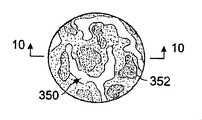
Translated fromJapanese本発明は椎骨間の脊椎融合移植片(埋込片)に関し、特に脊椎の2つの隣接した椎骨の解剖学的な前弯状態を回復して維持するように構成された脊椎融合移植に関する。 The present invention relates to spinal fusion implants between vertebrae, and in particular to spinal fusion implants configured to restore and maintain the anatomical lordosis of two adjacent vertebrae of the spine.
体間脊椎融合とは円板空間(通常椎間板が占めている椎骨間の空間)を通して隣接椎骨をブリッジする方法である。こうした融合を容易にするための種々の移植片がCloward,Brantiganその他の人により提案されている。一般に円筒状移植片は円板空間をまたいで各隣接椎骨の受け孔に嵌入することができる。このような孔はドリルで穿孔することができる。 Interbody spinal fusion is a method of bridging adjacent vertebrae through a disc space (the space between the vertebrae usually occupied by the intervertebral disc). Various implants have been proposed by Cloward, Brantigan and others to facilitate such fusion. In general, a cylindrical implant can be inserted into a receiving hole in each adjacent vertebra across the disc space. Such holes can be drilled.
頚堆と腰椎の両者は通常は前弯であり、前方に凸である。このような配列状態は脊椎の適正な機能にとり重要である。一般に脊椎融合による処置が必要なこれらの状態は前弯が失われることと関連している。従って、解剖学的な前弯の回復を可能にする脊椎融合移植片に対する要求がある。 Both the cervix and lumbar spine are usually lordosis and convex forward. Such an arrangement is important for proper functioning of the spine. These conditions, which generally require treatment by spinal fusion, are associated with the loss of sentinel. Accordingly, there is a need for a spinal fusion graft that allows for anatomical lordosis recovery.
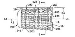
本発明は、人の脊椎の隣接した椎骨の間の外科的に補正された高さの円板空間に横から挿入される無ねじ脊椎融合移植片において、前記移植片は、移植されたときに前記隣接した椎骨に接触して両椎骨の相対屈曲を維持できるに充分な大きさを有するほぼ截頭円錐形の部分を有する本体を含み、前記本体は、挿入端と、後端と、前記隣接した椎骨に前記移植片を係止させる骨係止手段を含み、前記骨係止手段はほぼ円筒形状をなしている、人体適合性の材料から製作されている脊椎融合移植片を提供する。 The present invention relates to a screwless spinal fusion implant that is inserted laterally into a surgically corrected height disc space between adjacent vertebrae of a human spine when the implant is implanted. A body having a generally frustoconical portion large enough to contact the adjacent vertebrae and maintain relative flexion of both vertebrae, the body including an insertion end, a rear end, and the adjacent And a bone anchoring means for locking the graft to the vertebrae, wherein the bone anchoring means is substantially cylindrical in shape and is provided with a spinal fusion implant made of a human compatible material.
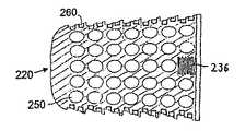
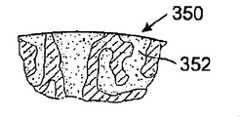
本発明は脊椎の所望の解剖学的前弯を達成するために、少なくとも部分的に截頭円錐形を有する各種の椎骨間脊椎融合移植片を提供する。好ましい実施例では、本発明の脊椎融合移植片は、少なくともその一部の箇所が、移植片の隣接椎骨に接触する部分に沿って、部分的または完全な截頭円錐形状の外側軌跡(包絡)を有するとともに、挿入端と後端とを有する。本発明の脊椎融合移植片は、上面と下面が截頭円錐形の位置部から構成され、且つ一方または両方の側面が切除されて移植片の縦軸線に平行な平面をなして平坦な壁を構成するように変形出来る。これらの移植片はその挿入端をよりテーパした形に形成することにより、椎骨への挿入を容易にすることが出来る。本発明の脊椎融合移植片はほぼむく及び/又は多孔室及び/又は中空でも良いし、さらに骨の内方成長を促進し及び/又は安定化するために表面粗化部を有しても良い。 The present invention provides various intervertebral spinal fusion implants that at least partially have a frustoconical shape to achieve the desired anatomical lordosis of the spine. In a preferred embodiment, the spinal fusion implant of the present invention has a partial or complete frustoconical outer trajectory (envelope) at least partially along the portion of the implant that contacts the adjacent vertebrae. And an insertion end and a rear end. The spinal fusion implant of the present invention has a flat wall with a top surface and a bottom surface that are formed from a frustoconical position, and one or both sides are cut away to form a plane parallel to the longitudinal axis of the graft. Can be modified to configure. These grafts can be easily inserted into the vertebrae by forming the insertion end into a more tapered shape. The spinal fusion implants of the present invention may be substantially stripped and / or perforated and / or hollow and may further have a surface roughening to promote and / or stabilize bone ingrowth. .
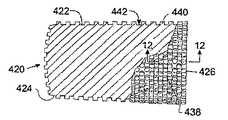
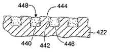
本発明の脊椎融合移植片は、融合促進物質を保持しあるいは骨の内方成長部の固定を行うために、その表面から内部へ延びる井戸状の凹所を有することが出来る。これらの凹所又は孔は移植片の内部に延びても良いし、あるいは貫通しても良く、あるいは互いに交差しても、しなくても良い。本発明の脊椎融合移植片は少なくとも一つの孔を通して移植片の表面に連通していても良い少なくとも一つの室を有する。この室は少なくとも一つのアクセス用の開口ないし孔を有し、そこに融合促進物質を充填するようにしても良い。アクセス用の孔は、移植片の安定性を増しあるいは移植片の表面積を増し、及び/又は移植片が容易に挿入出来るように助成するが逆方向の運動には抵抗するように、各種の表面不規則形状を用いることが出来る。本発明の脊椎融合移植片は上記の目的を達成するように全面的又は部分的に上記の目的を達成するために、粗面仕上げ、ぎざぎざ、前向き鋸歯状部、あるいは他の不規則部を有することが出来る。 The spinal fusion implant of the present invention can have a well-like recess extending inwardly from its surface to retain a fusion promoting substance or to fix bone ingrowth. These recesses or holes may extend into the implant, may penetrate, or may not intersect each other. The spinal fusion implant of the present invention has at least one chamber that may communicate with the surface of the implant through at least one hole. This chamber may have at least one access opening or hole, which may be filled with a fusion promoting substance. Access holes can be used on various surfaces to increase the stability of the graft or increase the surface area of the graft, and / or assist the graft to be easily inserted but resist reverse movement. Irregular shapes can be used. The spinal fusion implant of the present invention has a rough finish, jagged, forward sawtooth, or other irregularities to achieve the above objectives in full or in part to achieve the above objectives. I can do it.
本発明の脊椎融合移植片は従来技術に比して次の利点を有する。
1.本発明の脊椎融合移植片は少なくとも部分的に截頭円錐形を有するので、その先導縁部から後端へのテーパが融合すべき椎骨部分へ挿入することを容易にし且つ完全に挿入することを可能にする。
2.本発明の移植片の形状は移植片で置換すべき椎間板(椎間板の前端は後端よりも通常高い)に一致する形状を有するので、正常な前弯を可能にする。本発明の移植片は後部よりも前部の方が同様に高い。
3.本発明の移植片は、それを受け入れるように融合の現場で容易に作製出来る受部の幾何学的形状に一致する。The spinal fusion implant of the present invention has the following advantages over the prior art.
1. Since the spinal fusion implant of the present invention has at least a partial frustoconical shape, its leading edge to posterior taper facilitates and fully inserts into the vertebral portion to be fused. enable.
2. The shape of the implant of the present invention has a shape that matches the disc to be replaced with the implant (the front end of the disc is usually higher than the rear end), thus allowing for normal lordosis. The graft of the present invention is similarly higher at the front than at the rear.
3. The implant of the present invention conforms to the geometry of the receptacle that can be easily made at the site of fusion to accept it.
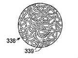
本発明の脊椎融合移植片は、人体への移植に適した任意の物質から製造でき、脊椎融合の目的に利用するに充分な機械的強度を有する、たとえばコバルト・クロム合金、ステンレス鋼、チタン又はその合金、生体吸収性のものを含めた各種プラスチック、各種セラミックス、その他の目的に適合したそれらの組み合わせを使用し得る。さらに、本発明の脊椎融合移植片は、形態を問わず、むくの材料、網状材料及び/又は多孔室材料から製作出来るし、また、直接骨融合過程に参加出来る材料、あるいは骨、形態発生蛋白質、ヒドロキシアパタイト、あるいは骨生成蛋白質等の化学物質で部分的又は全面的に充填され、構成され、処理され、あるいは被覆されて、それらを脊椎融合を模擬する目的に対して生活性を付与し得る。本発明の移植片は部分的に又は全面的に生体吸収性であっても良い。 The spinal fusion implants of the present invention can be made from any material suitable for implantation into the human body and have sufficient mechanical strength to be utilized for spinal fusion purposes, such as cobalt-chromium alloy, stainless steel, titanium or The alloys, various plastics, including those that are bioabsorbable, various ceramics, and other combinations suitable for other purposes can be used. Furthermore, the spinal fusion implant of the present invention can be made of any material, reticulated material and / or porous chamber material, regardless of form, and can directly participate in the bone fusion process, or bone, morphogenic protein. Can be partially or fully filled, structured, treated, or coated with chemicals such as hydroxyapatite, or bone-forming protein, to confer life for purposes of simulating spinal fusion . The implant of the present invention may be partially or fully bioabsorbable.
発明の目的
本発明の目的は、椎骨に容易に挿入出来るように、テーパ付き先導端(前端)を有する脊椎融合移植片を提供することである。OBJECT OF THE INVENTION It is an object of the present invention to provide a spinal fusion implant having a tapered leading end (anterior end) so that it can be easily inserted into a vertebra.
本発明の他の目的は、正常な椎間板のテーパに一致して一端から他端に向けて高さが変わるようにテーパしている脊椎融合移植片を提供することにある。 It is another object of the present invention to provide a spinal fusion graft that tapers to change in height from one end to the other, consistent with the normal disc taper.
本発明のさらに他の目的は脊椎融合行程中に、2つの隣接椎骨の解剖学的な整列状態と前弯を維持することが出来る脊椎融合移植片を提供することにある。 Yet another object of the present invention is to provide a spinal fusion implant that can maintain the anatomical alignment and lordosis of two adjacent vertebrae during the spinal fusion process.
本発明の他の目的は脊椎内でそれ自体で安定化する脊椎融合移植片を提供することにある。 It is another object of the present invention to provide a spinal fusion implant that is itself stabilized within the spine.
本発明のさらに他の目的は挿入すると隣接した椎骨が安定化される脊椎融合移植片を提供することにある。 Yet another object of the present invention is to provide a spinal fusion implant in which adjacent vertebrae are stabilized upon insertion.
本発明の別の目的は、融合促進物質を収容し、あるいはそれから構成され、あるいはそれで処理されているために、融合過程に関与することができる脊椎融合移植片を提供することにある。 It is another object of the present invention to provide a spinal fusion implant that can participate in the fusion process because it contains, consists of, or has been treated with a fusion promoting substance.
本発明のさらに他の目的は隣接した椎骨を脊椎融合過程において離間して支持することが出来る脊椎融合移植片を提供することである。 Yet another object of the present invention is to provide a spinal fusion implant that can support adjacent vertebrae spaced apart during a spinal fusion process.
本発明のさらに他の目的は、使用時に軟骨様椎骨の厚さを一定に保つことが出来る脊椎融合移植片を提供することにある。 Still another object of the present invention is to provide a spinal fusion implant that can maintain a constant thickness of the cartilage-like vertebra during use.
本発明のさらに別の目的は、融着箇所に移植片と相補形状をなす孔を容易に穿孔出来るような形状を有する脊椎融合移植片を提供することである。 Still another object of the present invention is to provide a spinal fusion graft having a shape that allows a hole complementary to the graft to be easily drilled at the fusion site.
本発明の更なる目的は、同一の椎間板空所に他の同一構造の移植片に近接して並べて挿入出来ると共に、上記他の移植片との総合幅が各移植片の幅の総和より小さくした、截頭円錐形の脊椎融合移植片を提供することである。 A further object of the present invention is that it can be inserted in the same intervertebral disc space adjacent to another graft of the same structure, and the total width with the other graft is smaller than the total width of each graft. To provide a truncated conical spinal fusion implant.
図1には本発明の脊椎融合移植片の実施例が示されており、移植片は全体的に数字220で示される。移植片220はほぼ截頭円錐形の本体を有し、脊椎の隣接する椎骨に接触する部分がほぼ截頭円錐形の外側軌跡(包絡)を有する。移植片220は隣接する椎骨に係止するのに適した前向きの複数の鋸歯状部240を有する。各鋸歯状部240は骨係止縁部242と傾斜部244を有する。鋸歯状部240は移植片220の中心線L4から測って半径R4を有し、その半径は挿入端224から後端226に向けて増大する。本体(鋸歯状部を除いた部分)から測った各鋸歯状部240の高さは移植片220の全体で一定である。 FIG. 1 shows an embodiment of a spinal fusion implant of the present invention, which is generally designated by
鋸歯状部240の傾斜部244が挿入時に傾斜面として作用し、一方反対方向には骨係合縁部242が運動に抵抗するので、移植片220の挿入の方が除去よりも容易である。これらの前向き鋸歯状部240は、椎骨の未除去部分が更なる運動を阻止してしっかり定着するまで移植片220の前進を助ける傾向を有する。移植片220は後端226に凹入したスロット234を有し、そこに移植片220を挿入するための器具を受け入れて係止するようになっている。凹入したスロット234はねじ孔236を有し、移植片220の器具へのねじ結合を可能にする。 Insertion of
好ましい実施例では、鋸歯状部240の骨係止縁部242は移植片220の台部222から測って最も高い部分で0.25〜2.0mmの高さ(根元直径)を有し、好ましくは頚椎で使用する場合には0.4mm、腰椎で使用する場合には1.25mmを有する。 In a preferred embodiment, the
図2を参照すると、移植片220の断面が示されている。移植片220は移植片220を貫通する孔250と移植片の表面に形成された凹所260を有する。凹所260は孔250に通じていてもいなくてもよい。好ましい実施例では孔250の直径は0.1〜6mm、好ましくは2〜3mmである。孔250と凹所260はほぼ円形であるが、目的に応じて任意の寸法、形状及び配置を有することができる。 Referring to FIG. 2, a cross section of the
図1Aを参照するに、移植片220は骨の成長を促すために椎骨に対して不規則表面を提示する多孔質の外表面238を有する。外表面238はまた融合促進物質を保持することができ、融合過程で骨に係合する増大した表面積を有すると共に、安定性を与える。外表面238及び/又は移植片全体は、融合促進剤物質を保持し、及び/又は骨の内方成長を促し、及び/又は融合過程で骨に係止するような、他の任意の多孔質材料又は粗化表面を有してもよい。移植片220はさらに、ヒドロキシアパタイト化合物、骨生成蛋白質、骨形態形成蛋白質のような生活性融合促進物質で被覆されていてもよい。移植片220はむくのものでも良いし、中空あるいは部分的に中空のものでもよい。 Referring to FIG. 1A, the
移植片220はむくのものとして記載したが、少なくとも部分的に中空のものにして、骨又は骨融合促進物質を保持できるようにすることができる。このような移植片は移植片の外側の骨が内部室へ向けて成長できるような孔を有することができる。このような構造は、米国特許出願第08/390131号(特許第5593409),08/074781号(特許第5484437)に記載がある。 Although the
図3Aを参照するに、移植片220に代わる他の実施例が移植片220’で示されている。移植片220’は移植片220と同様な構造を有するが、その本体が截頭円錐形を有すると共に、挿入端224’から後端226’まですべての鋸歯状部240’が縦軸線L4から測って一定の半径R3を有する点では違っている。鋸歯状部240’の高さは本体(鋸歯状部を除いた部分)から測って移植片220’の全体にわたり異なった高さを有する。このようにして、鋸歯状部240’は移植片220’のほぼ円筒形の外面形状を画定し、一方本体は截頭円錐形を有する。移植片220’の挿入を容易にするために移植片220’の挿入端224’は小直径のテーパ部223’を有する。 Referring to FIG. 3A, another alternative to the
図4〜5を参照すると、移植片220の他の実施例が数字220”で示されている。移植片220”は図1の移植片220と同様な構造を有し、縦軸線L5から測って、挿入端224”から後端226”へ向けて次第に増大する半径R5の鋸歯状部240”を有する。鋸歯状部240”はほぼ円筒形の本体222”から測った高さは移植片220”の全長にわたり一定でない。この実施例では、鋸歯状部の半径R5と高さは挿入端224”から後端226”へ向けて増大している。 4-5, another embodiment of an
図5に示したように、移植片220”は両側部が切除され、直径を挟んで対向する、縦軸線L5に平行な2つの平面を画定する側面270、272を有する。このようにして2個の同一の移植片220”を一方を側面270が他方の側面272が接触するようにして並べることができ、それにより、隣接する椎骨の骨と鋸歯状部240”との接触面積が最大になるようにすることができる。別法として、移植片220”は一方の側部だけが切り取られていてもよい。 As shown in FIG. 5, the
図6〜8には、本発明の他の実施例による椎骨融合移植片320aが示されている。移植片320aは鎖線で示した他の同一の移植片320bと並べて配置されている。移植片320aは、金属から製作してもよい糸を一緒に圧縮して、隣接する椎骨と接触する部分に沿う移植片320aの部分にほぼ沿っている部分的な截頭円錐形に成形した、網状材料より構成される本体322を有する。移植片320aは挿入端324と後端326とを有する。移植片320aは全部又は部分的にむくの、及び/又は多孔質の、及び/又は網状の材料から製作することができる。移植片320aは多孔質材料、網状材料、又は粗化した表面を有することができる。移植片320aはむくでも良いし、部分的に中空でも良いし、少なくとも1つの内室を有してもよい。図8に示したように、網状材料は成形され且つ圧縮一体化された多数の糸よりなり、それにより融合促進物質を保持することができ且つ骨の内方成長を可能にする間隙部339が、移植片320aの少なくとも外表面338に存在するようにする。 FIGS. 6-8 illustrate a
図9、図10を参照するに、別の形態では、移植片320aは人の海綿骨に類似の海綿状材料350から形成することができる。移植片は間隙部352を有し、そのため外表面338は図9〜10のような形状を有する。移植片320aは全体的又は部分的に海綿状材料から製作して、間隙部352が移植片の外表面338及び/又は内部全体に存在するようにし、それにより骨の内方成長を可能にし、骨癒着促進材料を保持することを可能にしてもよい。 Referring to FIGS. 9 and 10, in another form, the
図7を再び参照すると、移植片320aは同様な部分的な截頭円錐形を有するが、移植片320aの中心軸線に対して平行な平面をなす少なくとも一つの側面340を形成するように切除されている。この切除部の側面340は二つの移植片320a,320bを二つの隣接した椎骨の間に並べて密着配置するのに適する(米国特許出願第08/390131号参照)。移植片320aは部分的にねじ部、あるいは実施例で述べたような同様な他の手段とあるいは機能的に同等の他の手段を有することができる。 Referring again to FIG. 7, the
図11は、本発明の移植片の他の実施例の部分的に切除された側面図である。移植片420は隣接した椎骨に接触する部分に沿った截頭円錐形の本体を有し、また挿入端424と後端426を有する。移植片420は融合に参加しあるいは骨の成長を促進することができる骨保持部材を有することができる外表面438を有する。好ましい実施例では、表面438は多数の離間配置された柱状体440を有し、それらの間に粉砕した骨又は人工骨による内方成長促進物質を保持することができる不完全井戸状の多数の凹所442を有する。移植片420は表面438に適当な融合促進物質を充填または被覆することにより移植可能なように調製できる。 FIG. 11 is a partially cut away side view of another embodiment of the implant of the present invention. The
図12を参照すると、移植片420の表面438の拡大図が示されている。好ましい実施例では、柱状体440は頭部444が残りの部分よりも大きい直径を有し、それらの間の各凹所442は柱状体440とは逆の形状を有する。この凹所442と柱状体440の構成によると、骨物質の表面438への保持作用が大きくなり、さらに骨の内方成長により生成される骨融合塊への係止力が向上する。骨の内方成長は凹所442の底446へ向けて成長するにつれて幅が広くなるので、骨の内方成長は入口448から出ていくことは出来ず、凹所に閉じ込められる。移植片420の表面438は利用可能な表面積を増大するが、さらに粗化、フロック処理、又は他の表面を非平滑にする方法により、この表面積をさらに増すことが出来る。 Referring to FIG. 12, an enlarged view of the
好ましい実施例では、柱状体440は約0.1〜2mmの範囲の最大直径を有し、約0.1〜2mmの高さを有し、約0.1〜2mm互いに離間しているので、凹所442は約0.1〜2mmの幅を有することになる。柱状体の寸法、形状、及び分布は同一の移植片内で異なっても良い。
以上により本発明を好ましい実施例に関連して説明したが、本発明の範囲内で他の変形例が可能なことは明らかであろう。In a preferred embodiment, the
While the invention has been described in connection with the preferred embodiment, it will be apparent that other variations are possible within the scope of the invention.
220、220’、220” 移植片
222 台部
222” 円筒形の本体
223’ テーパ部
224、224’、224” 挿入端
226、226’、226” 後端
234 スロット
236 ねじ孔
238 外表面
240、240’、240” 鋸歯状部
242 骨係止縁部
244 傾斜部
250 孔
260 凹所
270、272 側面
320a,320b 移植片
322 本体
324 挿入端
326 後端
338 外表面
339 間隙部
340 側面
350 海綿状材料
352 間隙部
420 移植片
424 挿入端
426 後端
438 表面
440 柱状体
442 凹所
444 頭部
446 底
448 入口220, 220 ', 220 "
Claims (9)
Translated fromJapaneseApplications Claiming Priority (1)
| Application Number | Priority Date | Filing Date | Title |
|---|---|---|---|
| US08/484,928US6923810B1 (en) | 1988-06-13 | 1995-06-07 | Frusto-conical interbody spinal fusion implants |
Related Parent Applications (1)
| Application Number | Title | Priority Date | Filing Date |
|---|---|---|---|
| JP50115197ADivisionJP4011616B2 (en) | 1995-06-07 | 1996-06-06 | Frustoconical spinal fusion graft |
Publications (2)
| Publication Number | Publication Date |
|---|---|
| JP2006061708A JP2006061708A (en) | 2006-03-09 |
| JP4005613B2true JP4005613B2 (en) | 2007-11-07 |
Family
ID=23926224
Family Applications (2)
| Application Number | Title | Priority Date | Filing Date |
|---|---|---|---|
| JP50115197AExpired - LifetimeJP4011616B2 (en) | 1995-06-07 | 1996-06-06 | Frustoconical spinal fusion graft |
| JP2005296242AExpired - Fee RelatedJP4005613B2 (en) | 1995-06-07 | 2005-10-11 | Screwless spinal fusion graft |
Family Applications Before (1)
| Application Number | Title | Priority Date | Filing Date |
|---|---|---|---|
| JP50115197AExpired - LifetimeJP4011616B2 (en) | 1995-06-07 | 1996-06-06 | Frustoconical spinal fusion graft |
Country Status (11)
| Country | Link |
|---|---|
| US (5) | US6923810B1 (en) |
| EP (2) | EP0836457B1 (en) |
| JP (2) | JP4011616B2 (en) |
| KR (1) | KR19990022610A (en) |
| CN (1) | CN1149059C (en) |
| AT (2) | ATE274889T1 (en) |
| AU (1) | AU6036096A (en) |
| CA (1) | CA2224249C (en) |
| DE (3) | DE69633287T2 (en) |
| ES (1) | ES2293113T3 (en) |
| WO (1) | WO1996040019A1 (en) |
Families Citing this family (230)
| Publication number | Priority date | Publication date | Assignee | Title |
|---|---|---|---|---|
| DE20004692U1 (en)* | 2000-03-14 | 2001-07-26 | Sofamor Danek GmbH, 94469 Deggendorf | Vertebral implant for screwing into an intervertebral space |
| US6923810B1 (en)* | 1988-06-13 | 2005-08-02 | Gary Karlin Michelson | Frusto-conical interbody spinal fusion implants |
| US5609635A (en)* | 1988-06-28 | 1997-03-11 | Michelson; Gary K. | Lordotic interbody spinal fusion implants |
| FR2730158B1 (en)* | 1995-02-06 | 1999-11-26 | Jbs Sa | DEVICE FOR MAINTAINING A NORMAL SPACING BETWEEN VERTEBRES AND FOR THE REPLACEMENT OF MISSING VERTEBRES |
| ES2297092T3 (en) | 1997-02-11 | 2008-05-01 | Warsaw Orthopedic, Inc. | PREVIOUS CERVICAL PLATE OF UNIQUE BLOCK. |
| US6139550A (en) | 1997-02-11 | 2000-10-31 | Michelson; Gary K. | Skeletal plating system |
| DE19720241B4 (en)* | 1997-05-15 | 2005-12-29 | Eska Implants Gmbh & Co. | Interbody fusion implant |
| DE19750382A1 (en)* | 1997-11-13 | 1999-05-20 | Augustin Prof Dr Med Betz | Operative correction equipment for displaced vertebrae used in minimally invasive surgery |
| US6086593A (en) | 1998-06-30 | 2000-07-11 | Bonutti; Peter M. | Method and apparatus for use in operating on a bone |
| US6099531A (en) | 1998-08-20 | 2000-08-08 | Bonutti; Peter M. | Changing relationship between bones |
| US6241770B1 (en)* | 1999-03-05 | 2001-06-05 | Gary K. Michelson | Interbody spinal fusion implant having an anatomically conformed trailing end |
| EP1198208B1 (en)* | 1999-05-05 | 2013-07-10 | Warsaw Orthopedic, Inc. | Nested interbody spinal fusion implants |
| KR20010018331A (en)* | 1999-08-18 | 2001-03-05 | 정태섭 | Development of Bioactive Implant by Alkali Treatment |
| EP1645248B8 (en)* | 2000-02-04 | 2010-06-16 | Warsaw Orthopedic, Inc. | Expandable interbody spinal fusion implant having pivotally attached blocker |
| US6814756B1 (en)* | 2000-02-04 | 2004-11-09 | Gary K. Michelson | Expandable threaded arcuate interbody spinal fusion implant with lordotic configuration during insertion |
| US6500205B1 (en)* | 2000-04-19 | 2002-12-31 | Gary K. Michelson | Expandable threaded arcuate interbody spinal fusion implant with cylindrical configuration during insertion |
| US7182781B1 (en) | 2000-03-02 | 2007-02-27 | Regeneration Technologies, Inc. | Cervical tapered dowel |
| US6350283B1 (en) | 2000-04-19 | 2002-02-26 | Gary K. Michelson | Bone hemi-lumbar interbody spinal implant having an asymmetrical leading end and method of installation thereof |
| US7462195B1 (en) | 2000-04-19 | 2008-12-09 | Warsaw Orthopedic, Inc. | Artificial lumbar interbody spinal implant having an asymmetrical leading end |
| AU2001280962A1 (en)* | 2000-08-01 | 2002-02-13 | Regeneration Technologies, Inc. | Diaphysial cortical dowel |
| DK1355593T3 (en)* | 2001-01-30 | 2006-07-31 | Synthes Ag | Bone implant, especially intervertebral implant |
| DE60224850T2 (en)* | 2001-02-04 | 2009-01-22 | Warsaw Orthopedic, Inc., Warsaw | Instrumentation for introducing and positioning an expandable intervertebral fusion implant |
| AU2002247230B9 (en) | 2001-03-01 | 2007-05-10 | Warsaw Orthopedic, Inc. | Dynamic lordotic guard with movable extensions for creating an implantation space posteriorly in the lumbar spine and method for use thereof |
| US6896680B2 (en)* | 2001-03-01 | 2005-05-24 | Gary K. Michelson | Arcuate dynamic lordotic guard with movable extensions for creating an implantation space posteriorly in the lumbar spine |
| US6989031B2 (en) | 2001-04-02 | 2006-01-24 | Sdgi Holdings, Inc. | Hemi-interbody spinal implant manufactured from a major long bone ring or a bone composite |
| US6890355B2 (en) | 2001-04-02 | 2005-05-10 | Gary K. Michelson | Artificial contoured spinal fusion implants made of a material other than bone |
| US7105023B2 (en) | 2002-01-17 | 2006-09-12 | Concept Matrix, L.L.C. | Vertebral defect device |
| US8137402B2 (en)* | 2002-01-17 | 2012-03-20 | Concept Matrix Llc | Vertebral defect device |
| US8010180B2 (en) | 2002-03-06 | 2011-08-30 | Mako Surgical Corp. | Haptic guidance system and method |
| TW200304608A (en) | 2002-03-06 | 2003-10-01 | Z Kat Inc | System and method for using a haptic device in combination with a computer-assisted surgery system |
| US11202676B2 (en) | 2002-03-06 | 2021-12-21 | Mako Surgical Corp. | Neural monitor-based dynamic haptics |
| US8996169B2 (en) | 2011-12-29 | 2015-03-31 | Mako Surgical Corp. | Neural monitor-based dynamic haptics |
| AU2004212942A1 (en) | 2003-02-14 | 2004-09-02 | Depuy Spine, Inc. | In-situ formed intervertebral fusion device |
| ATE477757T1 (en)* | 2003-03-21 | 2010-09-15 | Synthes Gmbh | INTRAMEDULLARY NAIL |
| WO2004084742A1 (en) | 2003-03-24 | 2004-10-07 | Theken Surgical Llc | Spinal implant adjustment device |
| DE202004021289U1 (en) | 2003-05-14 | 2007-06-06 | Kraus, Kilian | Height-adjustable implant for insertion between vertebral bodies and handling tool |
| DE10357926B3 (en) | 2003-12-11 | 2005-09-01 | Deltacor Gmbh | Length adjustable spinal implant |
| CN100591305C (en)* | 2004-02-13 | 2010-02-24 | 小弗朗茨·科波夫 | Intervertebral implant and surgical method for lumbar spinal fusion |
| US8992618B2 (en) | 2004-04-26 | 2015-03-31 | DePuy Synthes Products, LLC | Intervertebral prosthesis or disk prosthesis |
| US7544208B1 (en) | 2004-05-03 | 2009-06-09 | Theken Spine, Llc | Adjustable corpectomy apparatus |
| US20060111786A1 (en)* | 2004-11-22 | 2006-05-25 | Orthopedic Development Corporation | Metallic prosthetic implant for use in minimally invasive acromio-clavicular shoulder joint hemi-arthroplasty |
| US20060111780A1 (en) | 2004-11-22 | 2006-05-25 | Orthopedic Development Corporation | Minimally invasive facet joint hemi-arthroplasty |
| US20060111779A1 (en)* | 2004-11-22 | 2006-05-25 | Orthopedic Development Corporation, A Florida Corporation | Minimally invasive facet joint fusion |
| US8021392B2 (en) | 2004-11-22 | 2011-09-20 | Minsurg International, Inc. | Methods and surgical kits for minimally-invasive facet joint fusion |
| US7736380B2 (en) | 2004-12-21 | 2010-06-15 | Rhausler, Inc. | Cervical plate system |
| US8992622B2 (en) | 2005-05-06 | 2015-03-31 | Titan Spine, Llc | Interbody spinal implant having a roughened surface topography |
| US8617248B2 (en) | 2005-05-06 | 2013-12-31 | Titan Spine, Llc | Spinal implant having variable ratios of the integration surface area to the axial passage area |
| US9168147B2 (en) | 2005-05-06 | 2015-10-27 | Titan Spine, Llc | Self-deploying locking screw retention device |
| US8480749B2 (en) | 2005-05-06 | 2013-07-09 | Titan Spine, Llc | Friction fit and vertebral endplate-preserving spinal implant |
| US8585767B2 (en) | 2005-05-06 | 2013-11-19 | Titan Spine, Llc | Endplate-preserving spinal implant with an integration plate having durable connectors |
| US8758443B2 (en) | 2005-05-06 | 2014-06-24 | Titan Spine, Llc | Implants with integration surfaces having regular repeating surface patterns |
| US8262737B2 (en) | 2005-05-06 | 2012-09-11 | Titan Spine, Llc | Composite interbody spinal implant having openings of predetermined size and shape |
| US8814939B2 (en) | 2005-05-06 | 2014-08-26 | Titan Spine, Llc | Implants having three distinct surfaces |
| US8758442B2 (en) | 2005-05-06 | 2014-06-24 | Titan Spine, Llc | Composite implants having integration surfaces composed of a regular repeating pattern |
| US20120312779A1 (en) | 2005-05-06 | 2012-12-13 | Titian Spine, LLC | Methods for manufacturing implants having integration surfaces |
| US8562685B2 (en) | 2005-05-06 | 2013-10-22 | Titan Spine, Llc | Spinal implant and integration plate for optimizing vertebral endplate contact load-bearing edges |
| US11096796B2 (en) | 2005-05-06 | 2021-08-24 | Titan Spine, Llc | Interbody spinal implant having a roughened surface topography on one or more internal surfaces |
| US8545568B2 (en) | 2005-05-06 | 2013-10-01 | Titan Spine, Llc | Method of using instruments and interbody spinal implants to enhance distraction |
| US8562684B2 (en) | 2005-05-06 | 2013-10-22 | Titan Spine, Llc | Endplate-preserving spinal implant with an integration plate having a roughened surface topography |
| US9125756B2 (en) | 2005-05-06 | 2015-09-08 | Titan Spine, Llc | Processes for producing regular repeating patterns on surfaces of interbody devices |
| US8591590B2 (en) | 2005-05-06 | 2013-11-26 | Titan Spine, Llc | Spinal implant having a transverse aperture |
| US8585766B2 (en) | 2005-05-06 | 2013-11-19 | Titan Spine, Llc | Endplate-preserving spinal implant with an integration plate having durable connectors |
| US8585765B2 (en) | 2005-05-06 | 2013-11-19 | Titan Spine, Llc | Endplate-preserving spinal implant having a raised expulsion-resistant edge |
| US8551176B2 (en) | 2005-05-06 | 2013-10-08 | Titan Spine, Llc | Spinal implant having a passage for enhancing contact between bone graft material and cortical endplate bone |
| US8403991B2 (en) | 2005-05-06 | 2013-03-26 | Titan Spine Llc | Implant with critical ratio of load bearing surface area to central opening area |
| US8435302B2 (en) | 2005-05-06 | 2013-05-07 | Titan Spine, Llc | Instruments and interbody spinal implants enhancing disc space distraction |
| US7867277B1 (en) | 2005-07-15 | 2011-01-11 | Nuvasive Inc. | Spinal fusion implant and related methods |
| AU2006279558B2 (en) | 2005-08-16 | 2012-05-17 | Izi Medical Products, Llc | Spinal tissue distraction devices |
| US8366773B2 (en) | 2005-08-16 | 2013-02-05 | Benvenue Medical, Inc. | Apparatus and method for treating bone |
| WO2008103781A2 (en) | 2007-02-21 | 2008-08-28 | Benvenue Medical, Inc. | Devices for treating the spine |
| US20070244562A1 (en)* | 2005-08-26 | 2007-10-18 | Magellan Spine Technologies, Inc. | Spinal implants and methods of providing dynamic stability to the spine |
| US20070050028A1 (en)* | 2005-08-26 | 2007-03-01 | Conner E S | Spinal implants and methods of providing dynamic stability to the spine |
| US7815682B1 (en) | 2005-09-24 | 2010-10-19 | Nuvasive, Inc. | Spinal fusion implant and related methods |
| WO2007136769A2 (en) | 2006-05-19 | 2007-11-29 | Mako Surgical Corp. | Method and apparatus for controlling a haptic device |
| WO2008070863A2 (en) | 2006-12-07 | 2008-06-12 | Interventional Spine, Inc. | Intervertebral implant |
| EP2124778B1 (en) | 2007-02-21 | 2019-09-25 | Benvenue Medical, Inc. | Devices for treating the spine |
| US8133261B2 (en) | 2007-02-26 | 2012-03-13 | Depuy Spine, Inc. | Intra-facet fixation device and method of use |
| US8894685B2 (en)* | 2007-04-13 | 2014-11-25 | DePuy Synthes Products, LLC | Facet fixation and fusion screw and washer assembly and method of use |
| US8043334B2 (en)* | 2007-04-13 | 2011-10-25 | Depuy Spine, Inc. | Articulating facet fusion screw |
| US7901439B2 (en)* | 2007-04-13 | 2011-03-08 | Horton Kenneth L | Allograft spinal facet fusion system |
| US8197513B2 (en)* | 2007-04-13 | 2012-06-12 | Depuy Spine, Inc. | Facet fixation and fusion wedge and method of use |
| WO2008153732A1 (en)* | 2007-05-22 | 2008-12-18 | Vg Innovations, Llc | Method and apparatus for spinal facet fusion |
| US8900307B2 (en) | 2007-06-26 | 2014-12-02 | DePuy Synthes Products, LLC | Highly lordosed fusion cage |
| US20110060366A1 (en)* | 2007-06-29 | 2011-03-10 | Stephen Heim | Facet Joint Implant and Related Methods |
| EP2208481B1 (en) | 2007-07-27 | 2016-12-28 | R Tree Innovations, LLC | Inter-Body Implantation System |
| US8808380B2 (en)* | 2007-08-27 | 2014-08-19 | William Casey Fox | Method and apparatus for an osteotomy fixation or arthrodesis cage |
| KR101570502B1 (en)* | 2007-10-19 | 2015-11-19 | 신세스 게엠바하 | Hemi-prosthesis |
| WO2009067486A2 (en)* | 2007-11-19 | 2009-05-28 | David Lee | Method and apparatus for spinal facet joint fusion using irregularly shaped cortical bone implants |
| WO2009067568A1 (en)* | 2007-11-19 | 2009-05-28 | Magellan Spine Technologies, Inc. | Spinal implants and methods |
| USD581538S1 (en) | 2007-12-14 | 2008-11-25 | Horton Kenneth L | Surgical implant |
| EP2237748B1 (en) | 2008-01-17 | 2012-09-05 | Synthes GmbH | An expandable intervertebral implant |
| US8267939B2 (en) | 2008-02-28 | 2012-09-18 | Stryker Spine | Tool for implanting expandable intervertebral implant |
| US8313528B1 (en) | 2008-03-27 | 2012-11-20 | Spinelogik, Inc. | Intervertebral fusion device and method of use |
| US8333804B1 (en) | 2008-03-27 | 2012-12-18 | Spinelogik, Inc. | Intervertebral fusion device and method of use |
| US8470040B2 (en)* | 2008-04-02 | 2013-06-25 | Pioneer Surgical Technology, Inc. | Intervertebral implant devices for supporting vertebrae and devices and methods for insertion thereof |
| US20100036498A1 (en)* | 2008-04-03 | 2010-02-11 | Mcdevitt Dennis | Fusion cage with reverse thread profile (rtp) |
| US8936641B2 (en) | 2008-04-05 | 2015-01-20 | DePuy Synthes Products, LLC | Expandable intervertebral implant |
| US8080046B2 (en)* | 2008-04-24 | 2011-12-20 | Loubert Suddaby | Facet joint fixation device |
| US8915962B1 (en) | 2008-04-24 | 2014-12-23 | Loubert S. Suddaby | Facet joint fixation device |
| US8808294B2 (en) | 2008-09-09 | 2014-08-19 | William Casey Fox | Method and apparatus for a multiple transition temperature implant |
| USD608001S1 (en) | 2008-12-09 | 2010-01-12 | Reardon Joshua J | Surgical implant inserter |
| USD601251S1 (en) | 2008-12-11 | 2009-09-29 | Horton Kenneth L | Surgical instrument |
| USD600806S1 (en) | 2008-12-11 | 2009-09-22 | Horton Kenneth L | Cannulated surgical instrument |
| USD605289S1 (en) | 2008-12-17 | 2009-12-01 | Horton Kenneth L | Surgical drill guide |
| USD610257S1 (en) | 2008-12-17 | 2010-02-16 | Horton Kenneth L | Surgical drill guide |
| US8133280B2 (en)* | 2008-12-19 | 2012-03-13 | Depuy Spine, Inc. | Methods and devices for expanding a spinal canal |
| US8535327B2 (en) | 2009-03-17 | 2013-09-17 | Benvenue Medical, Inc. | Delivery apparatus for use with implantable medical devices |
| US9526620B2 (en) | 2009-03-30 | 2016-12-27 | DePuy Synthes Products, Inc. | Zero profile spinal fusion cage |
| CN102481187B (en)* | 2009-03-31 | 2016-06-08 | 医学嵌入公司暨Imds共同创新公司 | Double bundle acl is repaired |
| US20100286785A1 (en)* | 2009-05-01 | 2010-11-11 | Danny Wayne Grayson | Method and apparatus for spinal interbody fusion |
| US20100312343A1 (en)* | 2009-06-04 | 2010-12-09 | Linares Medical Devices, Llc | Tip support insert for application to left/right articular processes to minimize abrasion between vertebrae and to maintain proper angle/lift for reducing nerve compression |
| USD629904S1 (en) | 2009-06-05 | 2010-12-28 | Horton Kenneth L | Spinous process implant |
| USD615653S1 (en) | 2009-06-05 | 2010-05-11 | Horton Kenneth L | Spinal implant |
| USD623747S1 (en) | 2009-06-30 | 2010-09-14 | Horton Kenneth L | Spinal implant |
| ES2563172T3 (en) | 2009-07-09 | 2016-03-11 | R Tree Innovations, Llc | Flexible intersomatic implant |
| USD629105S1 (en) | 2009-08-10 | 2010-12-14 | Horton Kenneth L | Spinous process implant |
| USD629519S1 (en) | 2009-08-10 | 2010-12-21 | Horton Kenneth L | Dowel implant |
| USD629905S1 (en) | 2009-08-28 | 2010-12-28 | Horton Kenneth L | Facet fusion wedge |
| USD629106S1 (en) | 2009-08-28 | 2010-12-14 | Horton Kenneth L | Facet fusion wedge |
| USD623748S1 (en) | 2009-09-24 | 2010-09-14 | Horton Kenneth L | Cervical spinal implant with lock |
| US20110238183A1 (en)* | 2009-09-26 | 2011-09-29 | Maly Richard S | Interbody Fusion Device |
| USD623749S1 (en) | 2009-10-23 | 2010-09-14 | Horton Kenneth L | Cervical spinal implant |
| US9028553B2 (en) | 2009-11-05 | 2015-05-12 | DePuy Synthes Products, Inc. | Self-pivoting spinal implant and associated instrumentation |
| USD622843S1 (en) | 2009-12-08 | 2010-08-31 | Horton Kenneth L | Spinous process inserter |
| USD622851S1 (en) | 2009-12-08 | 2010-08-31 | Horton Kenneth L | Spinous process reamer |
| USD629107S1 (en) | 2009-12-08 | 2010-12-14 | Horton Kenneth L | Spinous process implant |
| USD627460S1 (en) | 2009-12-08 | 2010-11-16 | Horton Kenneth L | Spinous process sizer distractor |
| USD629896S1 (en) | 2009-12-10 | 2010-12-28 | Horton Kenneth L | Spinous process tapered dilator |
| US9393129B2 (en) | 2009-12-10 | 2016-07-19 | DePuy Synthes Products, Inc. | Bellows-like expandable interbody fusion cage |
| US9480511B2 (en) | 2009-12-17 | 2016-11-01 | Engage Medical Holdings, Llc | Blade fixation for ankle fusion and arthroplasty |
| US9427324B1 (en) | 2010-02-22 | 2016-08-30 | Spinelogik, Inc. | Intervertebral fusion device and method of use |
| USD629520S1 (en) | 2010-03-18 | 2010-12-21 | Horton Kenneth L | Spinous process implant |
| US8979860B2 (en) | 2010-06-24 | 2015-03-17 | DePuy Synthes Products. LLC | Enhanced cage insertion device |
| US9907560B2 (en) | 2010-06-24 | 2018-03-06 | DePuy Synthes Products, Inc. | Flexible vertebral body shavers |
| US8623091B2 (en) | 2010-06-29 | 2014-01-07 | DePuy Synthes Products, LLC | Distractible intervertebral implant |
| US9089372B2 (en) | 2010-07-12 | 2015-07-28 | DePuy Synthes Products, Inc. | Pedicular facet fusion screw with plate |
| TW201215369A (en)* | 2010-10-01 | 2012-04-16 | Metal Ind Res & Dev Ct | Spinal implant structure and method for manufacturing the same |
| US9402732B2 (en) | 2010-10-11 | 2016-08-02 | DePuy Synthes Products, Inc. | Expandable interspinous process spacer implant |
| EP2629703B1 (en)* | 2010-10-19 | 2022-12-21 | VGI Medical, LLC | Apparatus for spinal facet fusion |
| EP2651341B1 (en) | 2010-12-16 | 2017-01-04 | Engage Medical Holdings, LLC | Arthroplasty systems and methods |
| US9358122B2 (en) | 2011-01-07 | 2016-06-07 | K2M, Inc. | Interbody spacer |
| US8814873B2 (en) | 2011-06-24 | 2014-08-26 | Benvenue Medical, Inc. | Devices and methods for treating bone tissue |
| EP2729092B1 (en) | 2011-08-16 | 2016-09-21 | Stryker European Holdings I, LLC | Expandable implant |
| US8968402B2 (en) | 2011-10-18 | 2015-03-03 | Arthrocare Corporation | ACL implants, instruments, and methods |
| US9254130B2 (en) | 2011-11-01 | 2016-02-09 | Hyun Bae | Blade anchor systems for bone fusion |
| US8992619B2 (en) | 2011-11-01 | 2015-03-31 | Titan Spine, Llc | Microstructured implant surfaces |
| US9717603B2 (en) | 2012-02-17 | 2017-08-01 | Timothy T. DAVIS | Implantable facet fusion devices |
| CA2880825C (en) | 2012-03-20 | 2021-03-16 | Titan Spine, Llc | Friction-fit spinal endplate and endplate-preserving method |
| US10238382B2 (en) | 2012-03-26 | 2019-03-26 | Engage Medical Holdings, Llc | Blade anchor for foot and ankle |
| US8882818B1 (en) | 2012-09-24 | 2014-11-11 | Vg Innovations, Llc | Method for deploying a fusion device for sacroiliac joint fusion |
| EP2716261A1 (en) | 2012-10-02 | 2014-04-09 | Titan Spine, LLC | Implants with self-deploying anchors |
| US9498349B2 (en) | 2012-10-09 | 2016-11-22 | Titan Spine, Llc | Expandable spinal implant with expansion wedge and anchor |
| US10022245B2 (en) | 2012-12-17 | 2018-07-17 | DePuy Synthes Products, Inc. | Polyaxial articulating instrument |
| US9717601B2 (en) | 2013-02-28 | 2017-08-01 | DePuy Synthes Products, Inc. | Expandable intervertebral implant, system, kit and method |
| US9522070B2 (en) | 2013-03-07 | 2016-12-20 | Interventional Spine, Inc. | Intervertebral implant |
| US9883874B1 (en) | 2013-03-08 | 2018-02-06 | Vg Innovations, Llc | Tool and method for implanting fusion device into sacroiliac joint |
| US10342675B2 (en) | 2013-03-11 | 2019-07-09 | Stryker European Holdings I, Llc | Expandable implant |
| US10085783B2 (en) | 2013-03-14 | 2018-10-02 | Izi Medical Products, Llc | Devices and methods for treating bone tissue |
| WO2014143894A1 (en)* | 2013-03-15 | 2014-09-18 | NuTech Spine, Inc. | Anterior lumbar fusion method and device |
| US9730802B1 (en) | 2014-01-14 | 2017-08-15 | Nuvasive, Inc. | Spinal fusion implant and related methods |
| US9615935B2 (en) | 2014-01-30 | 2017-04-11 | Titan Spine, Llc | Thermally activated shape memory spring assemblies for implant expansion |
| CN106163436B (en)* | 2014-03-10 | 2020-03-17 | 泰克里斯公司 | Device for removing bone cement from a bone cavity |
| US10028841B2 (en) | 2015-01-27 | 2018-07-24 | K2M, Inc. | Interbody spacer |
| US20160213405A1 (en) | 2015-01-27 | 2016-07-28 | K2M, Inc. | Vertebral plate systems and methods of use |
| US11426290B2 (en) | 2015-03-06 | 2022-08-30 | DePuy Synthes Products, Inc. | Expandable intervertebral implant, system, kit and method |
| US10449051B2 (en) | 2015-04-29 | 2019-10-22 | Institute for Musculoskeletal Science and Education, Ltd. | Implant with curved bone contacting elements |
| US10709570B2 (en) | 2015-04-29 | 2020-07-14 | Institute for Musculoskeletal Science and Education, Ltd. | Implant with a diagonal insertion axis |
| US10492921B2 (en) | 2015-04-29 | 2019-12-03 | Institute for Musculoskeletal Science and Education, Ltd. | Implant with arched bone contacting elements |
| JP6768001B2 (en) | 2015-04-29 | 2020-10-14 | インスティテュート フォー マスキュロスケレタル サイエンス アンド エジュケイション,リミテッド | Coiled implants and systems and how to make them |
| US9996739B2 (en)* | 2016-02-19 | 2018-06-12 | Conduent Business Services, Llc | System and method for automatic gait cycle segmentation |
| US20170367839A1 (en) | 2016-06-23 | 2017-12-28 | VGI Medical, LLC | Method and apparatus for spinal facet fusion |
| EP3474784A2 (en) | 2016-06-28 | 2019-05-01 | Eit Emerging Implant Technologies GmbH | Expandable and angularly adjustable intervertebral cages with articulating joint |
| US11510788B2 (en) | 2016-06-28 | 2022-11-29 | Eit Emerging Implant Technologies Gmbh | Expandable, angularly adjustable intervertebral cages |
| US10265189B2 (en) | 2016-09-13 | 2019-04-23 | Warsaw Orthopedic, Inc. | Interbody spinal fusion device |
| US10390955B2 (en) | 2016-09-22 | 2019-08-27 | Engage Medical Holdings, Llc | Bone implants |
| US11033394B2 (en) | 2016-10-25 | 2021-06-15 | Institute for Musculoskeletal Science and Education, Ltd. | Implant with multi-layer bone interfacing lattice |
| US10478312B2 (en) | 2016-10-25 | 2019-11-19 | Institute for Musculoskeletal Science and Education, Ltd. | Implant with protected fusion zones |
| US10888433B2 (en) | 2016-12-14 | 2021-01-12 | DePuy Synthes Products, Inc. | Intervertebral implant inserter and related methods |
| US10456272B2 (en) | 2017-03-03 | 2019-10-29 | Engage Uni Llc | Unicompartmental knee arthroplasty |
| US11540928B2 (en) | 2017-03-03 | 2023-01-03 | Engage Uni Llc | Unicompartmental knee arthroplasty |
| EP3592283B1 (en) | 2017-03-10 | 2024-05-08 | Alps Holding Llc | Hard-tissue implant comprising a bulk implant, a face, pillars, slots, and at least one support member |
| US11324606B2 (en) | 2017-03-10 | 2022-05-10 | Gary A. Zwick | Spinal interbody cage comprising a bulk interbody cage, a top face, a bottom face, pillars, and slots |
| US10357377B2 (en) | 2017-03-13 | 2019-07-23 | Institute for Musculoskeletal Science and Education, Ltd. | Implant with bone contacting elements having helical and undulating planar geometries |
| US10512549B2 (en) | 2017-03-13 | 2019-12-24 | Institute for Musculoskeletal Science and Education, Ltd. | Implant with structural members arranged around a ring |
| US10213317B2 (en) | 2017-03-13 | 2019-02-26 | Institute for Musculoskeletal Science and Education | Implant with supported helical members |
| US10667924B2 (en) | 2017-03-13 | 2020-06-02 | Institute for Musculoskeletal Science and Education, Ltd. | Corpectomy implant |
| US10398563B2 (en) | 2017-05-08 | 2019-09-03 | Medos International Sarl | Expandable cage |
| EP3415108B1 (en) | 2017-05-25 | 2024-09-04 | Stryker European Operations Holdings LLC | Fusion cage with integrated fixation and insertion features |
| US11344424B2 (en) | 2017-06-14 | 2022-05-31 | Medos International Sarl | Expandable intervertebral implant and related methods |
| US10940016B2 (en) | 2017-07-05 | 2021-03-09 | Medos International Sarl | Expandable intervertebral fusion cage |
| US11006981B2 (en) | 2017-07-07 | 2021-05-18 | K2M, Inc. | Surgical implant and methods of additive manufacturing |
| USD831828S1 (en)* | 2017-07-12 | 2018-10-23 | NuTech Spine, Inc. | Spinal implant |
| US10966843B2 (en) | 2017-07-18 | 2021-04-06 | DePuy Synthes Products, Inc. | Implant inserters and related methods |
| US11045331B2 (en) | 2017-08-14 | 2021-06-29 | DePuy Synthes Products, Inc. | Intervertebral implant inserters and related methods |
| WO2019051260A1 (en) | 2017-09-08 | 2019-03-14 | Pioneer Surgical Technology, Inc. | Intervertebral implants, instruments, and methods |
| USD907771S1 (en) | 2017-10-09 | 2021-01-12 | Pioneer Surgical Technology, Inc. | Intervertebral implant |
| US10744001B2 (en) | 2017-11-21 | 2020-08-18 | Institute for Musculoskeletal Science and Education, Ltd. | Implant with improved bone contact |
| US10940015B2 (en) | 2017-11-21 | 2021-03-09 | Institute for Musculoskeletal Science and Education, Ltd. | Implant with improved flow characteristics |
| US10695192B2 (en) | 2018-01-31 | 2020-06-30 | Institute for Musculoskeletal Science and Education, Ltd. | Implant with internal support members |
| US11806250B2 (en) | 2018-02-22 | 2023-11-07 | Warsaw Orthopedic, Inc. | Expandable spinal implant system and method of using same |
| CN111655203A (en) | 2018-02-22 | 2020-09-11 | 华沙整形外科股份有限公司 | Expandable spinal implant system and method of use |
| EP3755273B1 (en) | 2018-02-22 | 2025-04-30 | Warsaw Orthopedic, Inc. | Expandable spinal implant system |
| US11278427B2 (en) | 2018-04-10 | 2022-03-22 | Gary A. Zick, Trustee Of The Everest Trust Uta April 20, 2017 | Spinal interbody cage comprising top and bottom faces with mesh structures, pillars and slots |
| CN109223253A (en)* | 2018-08-16 | 2019-01-18 | 河南科技大学第附属医院 | A kind of breast prosthesis |
| US11446156B2 (en) | 2018-10-25 | 2022-09-20 | Medos International Sarl | Expandable intervertebral implant, inserter instrument, and related methods |
| JP7335428B2 (en) | 2019-09-11 | 2023-08-29 | アルプス ホールディング エルエルシー | An implant comprising a first set and a second set of pillars for attaching a tendon or ligament to hard tissue |
| US11534307B2 (en) | 2019-09-16 | 2022-12-27 | K2M, Inc. | 3D printed cervical standalone implant |
| US11426286B2 (en) | 2020-03-06 | 2022-08-30 | Eit Emerging Implant Technologies Gmbh | Expandable intervertebral implant |
| US11833059B2 (en) | 2020-11-05 | 2023-12-05 | Warsaw Orthopedic, Inc. | Expandable inter-body device, expandable plate system, and associated methods |
| US11963881B2 (en) | 2020-11-05 | 2024-04-23 | Warsaw Orthopedic, Inc. | Expandable inter-body device, system, and method |
| US11285014B1 (en) | 2020-11-05 | 2022-03-29 | Warsaw Orthopedic, Inc. | Expandable inter-body device, system, and method |
| US11517443B2 (en) | 2020-11-05 | 2022-12-06 | Warsaw Orthopedic, Inc. | Dual wedge expandable implant, system and method of use |
| US11517363B2 (en) | 2020-11-05 | 2022-12-06 | Warsaw Orthopedic, Inc. | Screw driver and complimentary screws |
| US11638653B2 (en) | 2020-11-05 | 2023-05-02 | Warsaw Orthopedic, Inc. | Surgery instruments with a movable handle |
| US11395743B1 (en) | 2021-05-04 | 2022-07-26 | Warsaw Orthopedic, Inc. | Externally driven expandable interbody and related methods |
| US12121453B2 (en) | 2020-11-05 | 2024-10-22 | Warsaw Orthopedic, Inc. | Dual wedge expandable implant with eyelets, system, and method of use |
| US12239544B2 (en) | 2020-11-05 | 2025-03-04 | Warsaw Orthopedic, Inc. | Rhomboid shaped implants |
| US11376134B1 (en) | 2020-11-05 | 2022-07-05 | Warsaw Orthopedic, Inc. | Dual expanding spinal implant, system, and method of use |
| US11291554B1 (en) | 2021-05-03 | 2022-04-05 | Medtronic, Inc. | Unibody dual expanding interbody implant |
| US12171439B2 (en) | 2020-11-05 | 2024-12-24 | Warsaw Orthopedic, Inc. | Protected drill |
| US12318308B2 (en) | 2020-11-05 | 2025-06-03 | Warsaw Orthopedic, Inc. | Dual expandable inter-body device |
| US11850160B2 (en) | 2021-03-26 | 2023-12-26 | Medos International Sarl | Expandable lordotic intervertebral fusion cage |
| US11752009B2 (en) | 2021-04-06 | 2023-09-12 | Medos International Sarl | Expandable intervertebral fusion cage |
| US12268614B2 (en) | 2021-06-24 | 2025-04-08 | Warsaw Orthopedic, Inc. | Interbody implant with adjusting shims |
| US11612499B2 (en) | 2021-06-24 | 2023-03-28 | Warsaw Orthopedic, Inc. | Expandable interbody implant |
| US12295865B2 (en) | 2021-06-24 | 2025-05-13 | Warsaw Orthopedic, Inc. | Expandable interbody implant and corresponding inserter |
| WO2022271280A1 (en) | 2021-06-24 | 2022-12-29 | Warsaw Orthopedic, Inc. | Expandable interbody implant and corresponding surgical tool |
| US11730608B2 (en) | 2021-07-13 | 2023-08-22 | Warsaw Orthopedic, Inc. | Monoblock expandable interbody implant |
| US11850163B2 (en) | 2022-02-01 | 2023-12-26 | Warsaw Orthopedic, Inc. | Interbody implant with adjusting shims |
| US12090064B2 (en) | 2022-03-01 | 2024-09-17 | Medos International Sarl | Stabilization members for expandable intervertebral implants, and related systems and methods |
Family Cites Families (257)
| Publication number | Priority date | Publication date | Assignee | Title |
|---|---|---|---|---|
| US350420A (en) | 1886-10-05 | Staple-driving implement | ||
| US1137585A (en) | 1915-02-05 | 1915-04-27 | Thornton Craig Jr | Dental appliance. |
| US2065659A (en) | 1934-08-04 | 1936-12-29 | Arthur V Cullen | Fastening method and means |
| US2243718A (en) | 1938-11-05 | 1941-05-27 | Moreira Francisco Elias Godoy | Surgical drill |
| US2181746A (en) | 1939-02-04 | 1939-11-28 | John R Siebrandt | Combination bone clamp and adjustable drill guide |
| GB564591A (en) | 1943-01-28 | 1944-10-04 | Courtaulds Ltd | Improvements in the manufacture and production of artificial threads, filaments and the like |
| US2543780A (en) | 1946-12-09 | 1951-03-06 | Herbert E Hipps | Bone graft apparatus |
| US2537070A (en) | 1948-12-27 | 1951-01-09 | Puy Mfg Company Inc De | Surgical appliance and method for fixation of bone fragments |
| US2514665A (en) | 1949-01-11 | 1950-07-11 | Myller Ernest | Medical instrument |
| US2677369A (en) | 1952-03-26 | 1954-05-04 | Fred L Knowles | Apparatus for treatment of the spinal column |
| US2774350A (en) | 1952-09-08 | 1956-12-18 | Jr Carl S Cleveland | Spinal clamp or splint |
| US2789558A (en) | 1953-09-17 | 1957-04-23 | Leslie V Rush | Medullary in driver and extractor |
| US2832343A (en) | 1955-04-12 | 1958-04-29 | Mose Clara Emilie Marie | Dilators |
| US2842131A (en) | 1957-05-27 | 1958-07-08 | George W Smith | Automatic drill |
| US2878809A (en) | 1958-01-23 | 1959-03-24 | Richards Mfg Company | Surgical drill attachment |
| US3128768A (en) | 1961-11-24 | 1964-04-14 | Rosemount Eng Co Ltd | Surgical drill |
| FR1338873A (en) | 1962-06-04 | 1963-10-04 | Comite Central De Fabricants D | Furnace for the thermal treatment of agglomerated fuels or classified coal |
| US3298372A (en) | 1963-12-17 | 1967-01-17 | Feinberg Maurice | Surgical hydrocephalus shunt sleeve for placement in a vertebra |
| US3426364A (en) | 1966-08-25 | 1969-02-11 | Colorado State Univ Research F | Prosthetic appliance for replacing one or more natural vertebrae |
| US3486505A (en) | 1967-05-22 | 1969-12-30 | Gordon M Morrison | Orthopedic surgical instrument |
| SE332486B (en) | 1968-12-09 | 1971-02-08 | Aga Ab | |
| US3618611A (en) | 1969-03-05 | 1971-11-09 | Julius C Urban | Vacuum rotary dissector |
| US3604487A (en) | 1969-03-10 | 1971-09-14 | Richard S Gilbert | Orthopedic screw driving means |
| US3948262A (en) | 1969-04-01 | 1976-04-06 | Alza Corporation | Novel drug delivery device |
| US3605123A (en) | 1969-04-29 | 1971-09-20 | Melpar Inc | Bone implant |
| CA962806A (en) | 1970-06-04 | 1975-02-18 | Ontario Research Foundation | Surgical prosthetic device |
| US3720959A (en) | 1970-08-26 | 1973-03-20 | G Hahn | Mandibular prosthetic apparatus |
| US3709219A (en) | 1970-11-27 | 1973-01-09 | W Halloran | Bone compression device |
| SE391122B (en) | 1971-01-25 | 1977-02-07 | Cutter Lab | PROTESTS IN THE FORM OF A SPINE BONIC DISC AND PROCEDURES FOR MANUFACTURE THEREOF |
| US3750652A (en) | 1971-03-05 | 1973-08-07 | J Sherwin | Knee retractor |
| US3719186A (en) | 1971-04-22 | 1973-03-06 | Univ Alabama In Birmingham | Surgical instrument for placement of bone pins and holes therefor |
| US3867950A (en) | 1971-06-18 | 1975-02-25 | Univ Johns Hopkins | Fixed rate rechargeable cardiac pacemaker |
| US3848601A (en) | 1972-06-14 | 1974-11-19 | G Ma | Method for interbody fusion of the spine |
| US3888260A (en) | 1972-06-28 | 1975-06-10 | Univ Johns Hopkins | Rechargeable demand inhibited cardiac pacer and tissue stimulator |
| DE2311817C2 (en) | 1973-03-09 | 1984-06-07 | Werner Dipl.-Ing. 8000 München Kraus | Stimulation current device to promote the healing of bone damage |
| DE2314573C2 (en) | 1973-03-23 | 1986-12-18 | Werner Dipl.-Ing. 8000 München Kraus | Device for promoting healing processes |
| US4070514A (en) | 1973-06-05 | 1978-01-24 | The United States Of America As Represented By The United States Department Of Energy | Method of fabricating graphite for use as a skeletal prosthesis and product thereof |
| US3905047A (en) | 1973-06-27 | 1975-09-16 | Posta Jr John J | Implantable ceramic bone prosthesis |
| DE2340546A1 (en) | 1973-08-10 | 1975-02-27 | Pfaudler Werke Ag | METALLIC IMPLANT AND PROCEDURE FOR ITS MANUFACTURING |
| US3892232A (en) | 1973-09-24 | 1975-07-01 | Alonzo J Neufeld | Method and apparatus for performing percutaneous bone surgery |
| JPS5060085A (en) | 1973-09-27 | 1975-05-23 | ||
| US3942535A (en) | 1973-09-27 | 1976-03-09 | G. D. Searle & Co. | Rechargeable tissue stimulating system |
| US3906550A (en)* | 1973-12-27 | 1975-09-23 | William Rostoker | Prosthetic device having a porous fiber metal structure |
| US4051905A (en) | 1974-03-28 | 1977-10-04 | Gerbruder Heller | Drill for percussion drilling machines |
| US3875595A (en) | 1974-04-15 | 1975-04-08 | Edward C Froning | Intervertebral disc prosthesis and instruments for locating same |
| US3916907A (en) | 1974-06-21 | 1975-11-04 | Wendell C Peterson | Spreader instrument for use in performing a spinal fusion |
| JPS5223514B2 (en) | 1974-09-25 | 1977-06-24 | ||
| US3952334A (en) | 1974-11-29 | 1976-04-27 | General Atomic Company | Biocompatible carbon prosthetic devices |
| FR2295729A1 (en) | 1974-12-27 | 1976-07-23 | Mahay Et Cie | TOTAL HIP PROSTHESIS |
| DE2505109A1 (en)* | 1975-02-07 | 1976-08-19 | Walter Schnabel | MODEL PLUG-IN COMPONENT |
| US4086701A (en) | 1975-04-07 | 1978-05-02 | Kyoto Ceramic Kabushiki Kaisha | Device for implanting an artificial endosseous element of ceramics and an implant method for use of the same |
| USD257511S (en) | 1975-09-08 | 1980-11-11 | Olin Corporation | Drill tool or the like |
| JPS5729348Y2 (en) | 1975-09-08 | 1982-06-26 | ||
| DE2546824C2 (en) | 1975-10-18 | 1986-05-07 | Ernst Leitz Wetzlar Gmbh, 6330 Wetzlar | Coated endoprosthesis and process for their manufacture |
| USD245259S (en) | 1976-01-29 | 1977-08-02 | Zimmer U.S.A. Inc. | Tibial prosthesis |
| GB1574825A (en) | 1976-03-31 | 1980-09-10 | Rubery Owen Fasteners Ltd | Screw threaded members and their manufacture |
| US4027392A (en) | 1976-05-10 | 1977-06-07 | Interface Biomedical Laboratories Corporation | Endosteal bionic tooth and implantation method |
| DE7615320U1 (en) | 1976-05-14 | 1979-02-08 | Pfaudler-Werke Ag, 6830 Schwetzingen | MEDICAL FASTENER |
| DE2621383A1 (en) | 1976-05-14 | 1977-12-01 | Gardner Denver Gmbh | METHOD OF PLACING IMPLANTS INTO BONE AND APPARATUS |
| US4082097A (en) | 1976-05-20 | 1978-04-04 | Pacesetter Systems Inc. | Multimode recharging system for living tissue stimulators |
| US4059115A (en) | 1976-06-14 | 1977-11-22 | Georgy Stepanovich Jumashev | Surgical instrument for operation of anterior fenestrated spondylodessis in vertebral osteochondrosis |
| US4142517A (en) | 1976-07-23 | 1979-03-06 | Contreras Guerrero De Stavropo | Apparatus for extracting bone marrow specimens |
| GB1550010A (en) | 1976-12-15 | 1979-08-08 | Ontario Research Foundation | Surgical prosthetic device or implant having pure metal porous coating |
| US4232679A (en) | 1977-01-26 | 1980-11-11 | Pacesetter Systems, Inc. | Programmable human tissue stimulator |
| GB1565178A (en) | 1977-02-24 | 1980-04-16 | Interfix Ltd | Bone screw |
| US4259072A (en) | 1977-04-04 | 1981-03-31 | Kyoto Ceramic Co., Ltd. | Ceramic endosseous implant |
| JPS53144194A (en) | 1977-05-20 | 1978-12-15 | Kureha Chemical Ind Co Ltd | Compound implanted material and making method thereof |
| US4258716A (en) | 1978-02-06 | 1981-03-31 | The University Of Melbourne | Microsurgical instruments |
| US4181457A (en) | 1978-02-10 | 1980-01-01 | Holmes Horace D | Tapping tool for making vibration resistant prevailing torque fastener |
| FR2429009A1 (en) | 1978-06-21 | 1980-01-18 | Roux Christiane | PROSTHESIS FOR ARTICULATION, PARTICULARLY COXO-FEMORAL, ARTIFICIAL |
| GB2029702B (en) | 1978-07-20 | 1982-12-15 | Secr Social Service Brit | Fracture fixation aooaratus |
| AT358715B (en) | 1978-09-04 | 1980-09-25 | Plansee Metallwerk | BUTCHING AND REJECTING DEVICE FOR BONE MARKING NAIL |
| US4197850A (en) | 1978-11-03 | 1980-04-15 | Pacesetter Systems, Inc. | Implantable human tissue stimulator with memory protect means |
| USD260525S (en) | 1978-12-04 | 1981-09-01 | Lassiter Will M | Channel drill and bolt combination |
| US4341206A (en) | 1978-12-19 | 1982-07-27 | Synthes Ag | Device for producing a hole in a bone |
| DE2910627A1 (en) | 1979-03-17 | 1980-09-25 | Schuett & Grundei Sanitaet | Implant which can be used as replacement for spongy bones - is built up from tolerated fibres which are implanted in bone cut=out |
| FR2460657A1 (en) | 1979-07-12 | 1981-01-30 | Anvar | BIODEGRADABLE IMPLANT FOR USE AS A BONE PROSTHESIS PIECE |
| US4333469A (en) | 1979-07-20 | 1982-06-08 | Telectronics Pty. Ltd. | Bone growth stimulator |
| US4492226A (en) | 1979-10-10 | 1985-01-08 | Vsesojuzny Nauchno-Issledovatelsky I Ispytatelny Institut Meditsinskoi Tekhniki | Device for uniting bone fragments |
| US4450834A (en) | 1979-10-18 | 1984-05-29 | Ace Orthopedic Manufacturing, Inc. | External fixation device |
| JPS6031706Y2 (en) | 1979-11-22 | 1985-09-21 | 京セラ株式会社 | Ceramic spinal prosthesis component |
| CH642250A5 (en) | 1979-12-22 | 1984-04-13 | Straumann Inst Ag | BALL JOINT PROSTHESIS WITH A CAP. |
| CH642840A5 (en) | 1980-02-08 | 1984-05-15 | Allo Pro Ag | SURGICAL IMPLANT, IN PARTICULAR HIP JOINT. |
| US4293962A (en) | 1980-02-14 | 1981-10-13 | Zimmer Usa, Inc. | Bone plug inserting system |
| SU1124960A1 (en) | 1980-02-19 | 1984-11-23 | Bokov Nikolaj F | Puncture instrument |
| US4289123A (en) | 1980-03-31 | 1981-09-15 | Dunn Harold K | Orthopedic appliance |
| US4405319A (en) | 1980-04-08 | 1983-09-20 | Renal Systems, Inc. | Porous titanium coating for blood access device |
| CH648197A5 (en) | 1980-05-28 | 1985-03-15 | Synthes Ag | IMPLANT AND SCREW FASTENING ON ITS BONE. |
| GB2076657A (en) | 1980-05-31 | 1981-12-09 | Atkins Brian Norman | Apparatus for external fixation of part of the human or animal skeletal structure |
| CA1146301A (en)* | 1980-06-13 | 1983-05-17 | J. David Kuntz | Intervertebral disc prosthesis |
| DE3031905A1 (en) | 1980-08-23 | 1982-03-04 | L. & C. Steinmüller GmbH, 5270 Gummersbach | BURNER SYSTEM |
| GB2083754B (en) | 1980-09-15 | 1984-04-26 | Rezaian Seyed Mahmoud | Spinal fixator |
| US4309777A (en) | 1980-11-13 | 1982-01-12 | Patil Arun A | Artificial intervertebral disc |
| CH646857A5 (en) | 1980-11-18 | 1984-12-28 | Sulzer Ag | SPONDYLODESIS STABILIZER. |
| US4414979A (en) | 1981-02-23 | 1983-11-15 | Telectronics Pty. Ltd. | Monitorable bone growth stimulator |
| JPS57163309A (en) | 1981-04-01 | 1982-10-07 | Olympus Optical Co Ltd | Capsule apparatus for medical use |
| EP0077159A1 (en) | 1981-10-14 | 1983-04-20 | Brian Norman Atkins | Vertebrae spreader |
| BR8107560A (en) | 1981-11-19 | 1983-07-05 | Luiz Romariz Duarte | ULTRASONIC STIMULATION OF BONE FRACTURE CONSOLIDATION |
| US4501269A (en)* | 1981-12-11 | 1985-02-26 | Washington State University Research Foundation, Inc. | Process for fusing bone joints |
| JPS6043984B2 (en) | 1982-02-27 | 1985-10-01 | 素麿 小山 | vertebral body spacer |
| US4439152A (en) | 1982-03-04 | 1984-03-27 | Small Irwin A | Method of jawbone abutment implant for dental prostheses and implant device |
| US4542539A (en) | 1982-03-12 | 1985-09-24 | Artech Corp. | Surgical implant having a graded porous coating |
| US4547390A (en) | 1982-03-12 | 1985-10-15 | Medical Biological Sciences, Inc. | Process of making implantable prosthesis material of modified polymeric acrylic (PMMA) beads coated with PHEMA and barium sulfate |
| US4535485A (en) | 1982-03-12 | 1985-08-20 | Medical Biological Sciences, Inc. | Polymeric acrylic prothesis |
| US4549547A (en) | 1982-07-27 | 1985-10-29 | Trustees Of The University Of Pennsylvania | Implantable bone growth stimulator |
| GB2126094A (en) | 1982-08-26 | 1984-03-21 | Brian Norman Atkins | Device for holding the bones of the wrist and forearm after setting or during arthrodesis of the wrist |
| US4545374A (en) | 1982-09-03 | 1985-10-08 | Jacobson Robert E | Method and instruments for performing a percutaneous lumbar diskectomy |
| US4600000A (en) | 1982-09-16 | 1986-07-15 | Edwards Charles C | External fixation system |
| US4552200A (en) | 1982-09-30 | 1985-11-12 | Southwire Company | Control in continuous casting to enhance feeding |
| JPS59501816A (en) | 1982-10-01 | 1984-11-01 | ジエフコ−ト,ケイス ウイリアム | electrical therapy device |
| US4535374A (en) | 1982-11-04 | 1985-08-13 | Amcodyne Incorporated | Whitney-type head loading/unloading apparatus |
| US4497320A (en) | 1983-02-14 | 1985-02-05 | Rudolph Beaver, Inc. | Surgical blade unit |
| US4481943A (en) | 1983-03-09 | 1984-11-13 | Michelson Gary K | Orthopedic support frame |
| SU1107854A1 (en) | 1983-03-30 | 1984-08-15 | Харьковский Научно-Исследовательский Институт Ортопедии И Травматологии Им.Проф.М.И.Ситенко | Spine fixative |
| US4570623A (en) | 1983-06-02 | 1986-02-18 | Pfizer Hospital Products Group Inc. | Arched bridge staple |
| USD281814S (en) | 1983-07-13 | 1985-12-17 | Techmedica, Inc. | Osteotomy staple |
| US4570624A (en) | 1983-08-10 | 1986-02-18 | Henry Ford Hospital | Universal guide for inserting parallel pins |
| IL69888A0 (en) | 1983-10-03 | 1984-01-31 | Avmedica Ltd | Unilateral external fixation system for small bones |
| US4554914A (en) | 1983-10-04 | 1985-11-26 | Kapp John P | Prosthetic vertebral body |
| SU1222254A1 (en) | 1983-11-09 | 1986-04-07 | Bogosyan Aleksandr B | Needle for intraosseous injection |
| US4553273A (en) | 1983-11-23 | 1985-11-19 | Henry Ford Hospital | Vertebral body prosthesis and spine stabilizing method |
| US4611581A (en) | 1983-12-16 | 1986-09-16 | Acromed Corporation | Apparatus for straightening spinal columns |
| US4696290A (en) | 1983-12-16 | 1987-09-29 | Acromed Corporation | Apparatus for straightening spinal columns |
| US4655777A (en) | 1983-12-19 | 1987-04-07 | Southern Research Institute | Method of producing biodegradable prosthesis and products therefrom |
| SU1217374A1 (en) | 1984-02-03 | 1986-03-15 | Институт Сейсмологии | Endoscopic knife |
| US4604995A (en) | 1984-03-30 | 1986-08-12 | Stephens David C | Spinal stabilizer |
| US4653486A (en) | 1984-04-12 | 1987-03-31 | Coker Tom P | Fastener, particularly suited for orthopedic use |
| DE3414514A1 (en) | 1984-04-13 | 1985-10-24 | Biotronik Meß- und Therapiegeräte GmbH & Co Ingenieurbüro Berlin, 1000 Berlin | SCREW-IN PAN FOR AN ARTIFICIAL HIP JOINT |
| US4608052A (en) | 1984-04-25 | 1986-08-26 | Minnesota Mining And Manufacturing Company | Implant with attachment surface |
| US4619264A (en) | 1984-06-14 | 1986-10-28 | Singh Om P | Method and apparatus for treatment of fresh fractures, delayed unions and non-unions of living bone |
| US4736738A (en) | 1984-07-09 | 1988-04-12 | Matej Lipovsek | Instrument kit and procedure for performing posterior lumbar interbody fusion |
| EP0176728B1 (en) | 1984-09-04 | 1989-07-26 | Humboldt-Universität zu Berlin | Intervertebral-disc prosthesis |
| GB2164277A (en) | 1984-09-12 | 1986-03-19 | Univ Manchester | A bone drill |
| FR2570594B1 (en) | 1984-09-26 | 1989-02-24 | Kehr Pierre | VERTEBRAL PROSTHESIS, PARTICULARLY FOR CERVICAL VERTEBRES |
| US4602638A (en) | 1984-10-03 | 1986-07-29 | Eddie Adams | Apparatus and method for invasive electrical stimulation of bone fractures |
| CA1264674A (en) | 1984-10-17 | 1990-01-23 | Paul Ducheyne | Porous flexible metal fiber material for surgical implantation |
| US4665920A (en) | 1984-11-28 | 1987-05-19 | Minnesota Mining And Manufacturing Company | Skeletal tissue stimulator and a low voltage oscillator circuit for use therein |
| ES283078Y (en) | 1984-11-30 | 1985-12-16 | Otero Vich Jose M. | BONE INSERT FOR CERVICAL INTERSOMATIC ARTHRODESIS |
| US4877020A (en) | 1984-11-30 | 1989-10-31 | Vich Jose M O | Apparatus for bone graft |
| DE3445738A1 (en) | 1984-12-14 | 1986-06-19 | Draenert Klaus | IMPLANT FOR BONE REINFORCEMENT AND ANCHORING OF BONE SCREWS, IMPLANTS OR IMPLANT PARTS |
| JPS61122859U (en) | 1985-01-19 | 1986-08-02 | ||
| US4721103A (en) | 1985-01-31 | 1988-01-26 | Yosef Freedland | Orthopedic device |
| FR2576779B1 (en) | 1985-02-07 | 1988-10-07 | Tornier Sa | ASSEMBLY DEVICE BETWEEN A BONE IMPLANT AND THE TOOL FOR ITS PLACEMENT |
| US4698375A (en) | 1985-02-19 | 1987-10-06 | The Dow Chemical Company | Composites of unsintered calcium phosphates and synthetic biodegradable polymers useful as hard tissue prosthetics |
| US4661536A (en) | 1985-02-19 | 1987-04-28 | The Dow Chemical Company | Process for the preparation of hard tissue prosthetics |
| US4636526A (en) | 1985-02-19 | 1987-01-13 | The Dow Chemical Company | Composites of unsintered calcium phosphates and synthetic biodegradable polymers useful as hard tissue prosthetics |
| US4634720A (en) | 1985-02-19 | 1987-01-06 | The Dow Chemical Company | Process for the preparation of hard tissue prosthetics |
| US5273964A (en)* | 1985-03-20 | 1993-12-28 | Lemons J E | Inorganic and organic composition for treatment of bone lesions |
| US4592346A (en) | 1985-04-08 | 1986-06-03 | Jurgutis John A | Orthopedic staple |
| US4636217A (en) | 1985-04-23 | 1987-01-13 | Regents Of The University Of Minnesota | Anterior spinal implant |
| FR2581336B1 (en) | 1985-05-02 | 1989-05-05 | Collomb Jean | WRENCH FOR SCREWING A PART WITH A HEAD WITH A SIZE AND A THREADED BORE |
| US4599086A (en) | 1985-06-07 | 1986-07-08 | Doty James R | Spine stabilization device and method |
| US4743260A (en) | 1985-06-10 | 1988-05-10 | Burton Charles V | Method for a flexible stabilization system for a vertebral column |
| US4645503A (en) | 1985-08-27 | 1987-02-24 | Orthomatrix Inc. | Moldable bone-implant material |
| US4743256A (en) | 1985-10-04 | 1988-05-10 | Brantigan John W | Surgical prosthetic implant facilitating vertebral interbody fusion and method |
| JPH0655213B2 (en) | 1985-12-27 | 1994-07-27 | 京セラ株式会社 | Lumbar spine block |
| US4664567A (en) | 1986-02-06 | 1987-05-12 | Bijur Lubricating Corp. | Drill bit |
| US4903882A (en) | 1986-03-10 | 1990-02-27 | Long Gregory T | Driving tool for an electrical staple |
| DE3608163A1 (en) | 1986-03-12 | 1987-09-24 | Walter A Dr Med Laabs | Device for dynamically/rigidly locking the distal and proximal parts of fractured bones |
| US4677883A (en) | 1986-06-09 | 1987-07-07 | Lee Wen Hsin | Cork screw |
| DE3620549A1 (en) | 1986-06-19 | 1987-12-23 | S & G Implants Gmbh | IMPLANT FOR FIXING NEXT SPINE BONES OF THE SPINE |
| GB8620937D0 (en) | 1986-08-29 | 1986-10-08 | Shepperd J A N | Spinal implant |
| US4769881A (en) | 1986-09-02 | 1988-09-13 | Pedigo Irby R | High precision tens apparatus and method of use |
| US4713004A (en) | 1986-09-04 | 1987-12-15 | Vent Plant Corporation | Submergible screw-type dental implant and method of utilization |
| US4710075A (en) | 1986-10-01 | 1987-12-01 | Boehringer Mannheim Corporation | Adjustable drill gauge |
| US4805602A (en) | 1986-11-03 | 1989-02-21 | Danninger Medical Technology | Transpedicular screw and rod system |
| DE3637314A1 (en) | 1986-11-03 | 1988-05-11 | Lutz Biedermann | SPACE HOLDER IMPLANT |
| US4834757A (en) | 1987-01-22 | 1989-05-30 | Brantigan John W | Prosthetic implant |
| US5116304A (en) | 1987-01-28 | 1992-05-26 | Cadwell Industries, Inc. | Magnetic stimulator with skullcap-shaped coil |
| CA1283501C (en) | 1987-02-12 | 1991-04-30 | Thomas P. Hedman | Artificial spinal disc |
| US4714469A (en) | 1987-02-26 | 1987-12-22 | Pfizer Hospital Products Group, Inc. | Spinal implant |
| US4790303A (en) | 1987-03-11 | 1988-12-13 | Acromed Corporation | Apparatus and method for securing bone graft |
| DE3711091A1 (en) | 1987-04-02 | 1988-10-13 | Kluger Patrick | DEVICE FOR SETTING UP A SPINE WITH A DAMAGED SPINE |
| US4781591A (en) | 1987-04-06 | 1988-11-01 | Allen James P | Endosteal implant and method for performing implantation thereof |
| US4863477A (en) | 1987-05-12 | 1989-09-05 | Monson Gary L | Synthetic intervertebral disc prosthesis |
| CH672588A5 (en) | 1987-07-09 | 1989-12-15 | Sulzer Ag | |
| GB8718627D0 (en) | 1987-08-06 | 1987-09-09 | Showell A W Sugicraft Ltd | Spinal implants |
| US4779012A (en) | 1987-08-12 | 1988-10-18 | Honeywell Inc. | Track-and-hold amplifier |
| US4772287A (en)* | 1987-08-20 | 1988-09-20 | Cedar Surgical, Inc. | Prosthetic disc and method of implanting |
| FR2624719B1 (en) | 1987-12-18 | 1990-05-11 | Zimmer Sa | DRILLING PROBE, PARTICULARLY FOR POSITIONING AND FIXING A MEDULAR NAIL |
| US4830000A (en) | 1987-12-31 | 1989-05-16 | Aspen Laboratories, Inc. | Surgical drill |
| US4851008A (en) | 1988-02-01 | 1989-07-25 | Orthomet, Inc. | Bone implant prosthesis with substantially stress-free outer surface |
| US4865603A (en) | 1988-02-04 | 1989-09-12 | Joint Medical Products Corporation | Metallic prosthetic devices having micro-textured outer surfaces |
| KR910000337B1 (en)* | 1988-03-08 | 1991-01-24 | 반도스포츠 주식회사 | Amphibious Car Toy |
| DE3809793A1 (en) | 1988-03-23 | 1989-10-05 | Link Waldemar Gmbh Co | SURGICAL INSTRUMENT SET |
| US4950296A (en)* | 1988-04-07 | 1990-08-21 | Mcintyre Jonathan L | Bone grafting units |
| US4848327A (en) | 1988-05-23 | 1989-07-18 | Perdue Kevin D | Apparatus and procedure for blind alignment of fasteners extended through transverse holes in an orthopedic locking nail |
| US4911718A (en) | 1988-06-10 | 1990-03-27 | University Of Medicine & Dentistry Of N.J. | Functional and biocompatible intervertebral disc spacer |
| US5015247A (en) | 1988-06-13 | 1991-05-14 | Michelson Gary K | Threaded spinal implant |
| US5484437A (en)* | 1988-06-13 | 1996-01-16 | Michelson; Gary K. | Apparatus and method of inserting spinal implants |
| US6923810B1 (en) | 1988-06-13 | 2005-08-02 | Gary Karlin Michelson | Frusto-conical interbody spinal fusion implants |
| CA1333209C (en) | 1988-06-28 | 1994-11-29 | Gary Karlin Michelson | Artificial spinal fusion implants |
| IT215084Z2 (en) | 1988-08-03 | 1990-07-30 | Torino A | VARIABLE EXCURSION CAMBRA |
| AU624627B2 (en) | 1988-08-18 | 1992-06-18 | Johnson & Johnson Orthopaedics, Inc. | Functional and biocompatible intervertebral disc spacer containing elastomeric material of varying hardness |
| US4960420A (en) | 1988-08-23 | 1990-10-02 | Marlowe Goble E | Channel ligament clamp and system |
| US4961740B1 (en)* | 1988-10-17 | 1997-01-14 | Surgical Dynamics Inc | V-thread fusion cage and method of fusing a bone joint |
| DE3841704A1 (en) | 1988-12-10 | 1990-06-21 | Imz Fertigung Vertrieb | IMPLANTABLE FASTENER FOR EXTRA-ORAL APPLICATIONS |
| US4968316A (en) | 1988-12-12 | 1990-11-06 | Hergenroeder Patrick T | Arthroscopic ankle joint distraction method |
| US4955885A (en) | 1988-12-21 | 1990-09-11 | Zimmer, Inc. | Surgical slider instrument and method of using instrument |
| US4969888A (en) | 1989-02-09 | 1990-11-13 | Arie Scholten | Surgical protocol for fixation of osteoporotic bone using inflatable device |
| CA1318469C (en) | 1989-02-15 | 1993-06-01 | Acromed Corporation | Artificial disc |
| US5062845A (en) | 1989-05-10 | 1991-11-05 | Spine-Tech, Inc. | Method of making an intervertebral reamer |
| US4927421A (en) | 1989-05-15 | 1990-05-22 | Marlowe Goble E | Process of endosteal fixation of a ligament |
| US5030236A (en) | 1989-06-19 | 1991-07-09 | Intermedics Orthopedics, Inc. | Apparatus for enhancing biointegration of bony and endoprosthesis structures |
| US5458638A (en) | 1989-07-06 | 1995-10-17 | Spine-Tech, Inc. | Non-threaded spinal implant |
| US4936848A (en)* | 1989-09-22 | 1990-06-26 | Bagby George W | Implant for vertebrae |
| US5055104A (en) | 1989-11-06 | 1991-10-08 | Surgical Dynamics, Inc. | Surgically implanting threaded fusion cages between adjacent low-back vertebrae by an anterior approach |
| AU3591093A (en) | 1989-11-17 | 1993-09-01 | Thomas L. Sheridan | Continuously engaged tangential driving tool |
| US5059193A (en) | 1989-11-20 | 1991-10-22 | Spine-Tech, Inc. | Expandable spinal implant and surgical method |
| US4987904A (en) | 1990-03-22 | 1991-01-29 | Wilson James T | Method and apparatus for bone size gauging |
| US5108422A (en) | 1990-10-22 | 1992-04-28 | United States Surgical Corporation | Skin fastener |
| ATE120637T1 (en) | 1990-12-19 | 1995-04-15 | Haerle Anton | BONE REPLACEMENT. |
| DE4104359A1 (en) | 1991-02-13 | 1992-08-20 | Implex Gmbh | CHARGING SYSTEM FOR IMPLANTABLE HOERHILFEN AND TINNITUS MASKERS |
| US5217479A (en) | 1991-02-14 | 1993-06-08 | Linvatec Corporation | Surgical cutting instrument |
| US5123926A (en) | 1991-02-22 | 1992-06-23 | Madhavan Pisharodi | Artificial spinal prosthesis |
| DE69209494T2 (en) | 1991-02-22 | 1996-10-31 | Pisharodi Madhavan | IMPLANT FROM AN EXPANDABLE INTERMEDIATE DISC |
| US5171278A (en) | 1991-02-22 | 1992-12-15 | Madhavan Pisharodi | Middle expandable intervertebral disk implants |
| US5192327A (en) | 1991-03-22 | 1993-03-09 | Brantigan John W | Surgical prosthetic implant for vertebrae |
| US5112336A (en) | 1991-05-14 | 1992-05-12 | Intermedics Orthopedics, Inc. | Drill guide and template for prosthetic devices |
| US5306307A (en) | 1991-07-22 | 1994-04-26 | Calcitek, Inc. | Spinal disk implant |
| DE59108588D1 (en)* | 1991-08-07 | 1997-04-10 | Oscobal Ag | Endoprosthesis with a metal wire |
| US5263953A (en) | 1991-12-31 | 1993-11-23 | Spine-Tech, Inc. | Apparatus and system for fusing bone joints |
| US5258031A (en) | 1992-01-06 | 1993-11-02 | Danek Medical | Intervertebral disk arthroplasty |
| GB9200214D0 (en) | 1992-01-06 | 1992-02-26 | Zimmer Limited | Apparatus for use in fusion of adjacent bodies |
| DE4302397C2 (en) | 1992-01-28 | 2003-08-21 | Pentax Corp | Artificial vertebral spacer |
| US5396880A (en) | 1992-04-08 | 1995-03-14 | Danek Medical, Inc. | Endoscope for direct visualization of the spine and epidural space |
| EP0566810B1 (en) | 1992-04-21 | 1996-08-14 | SULZER Medizinaltechnik AG | Artificial spinal disc |
| US5324295A (en) | 1992-04-24 | 1994-06-28 | Shapiro Michael R | Drill guide for surgical pins |
| US5306309A (en) | 1992-05-04 | 1994-04-26 | Calcitek, Inc. | Spinal disk implant and implantation kit |
| DE4220215C2 (en) | 1992-06-20 | 1994-09-22 | S & G Implants Gmbh | Implant to fix adjacent vertebrae |
| US5246458A (en) | 1992-10-07 | 1993-09-21 | Graham Donald V | Artificial disk |
| US5314427A (en) | 1992-10-13 | 1994-05-24 | Marlowe Goble E | Channel ligament clamp |
| DE9216092U1 (en) | 1992-11-26 | 1993-01-14 | S + G Implants GmbH, 2400 Lübeck | Disc-shaped implant for stiffening adjacent vertebral bones |
| US5292252A (en) | 1992-12-14 | 1994-03-08 | Impla-Med, Inc. | Stimulator healing cap |
| US5364399A (en) | 1993-02-05 | 1994-11-15 | Danek Medical, Inc. | Anterior cervical plating system |
| CA2155422C (en)* | 1993-02-10 | 2005-07-12 | Stephen D. Kuslich | Spinal stabilization surgical method |
| FR2703580B1 (en) | 1993-03-03 | 1997-10-17 | Gilles Robert | Cervical interbody fusion cage. |
| US5352229A (en) | 1993-05-12 | 1994-10-04 | Marlowe Goble E | Arbor press staple and washer and method for its use |
| US5370662A (en) | 1993-06-23 | 1994-12-06 | Kevin R. Stone | Suture anchor assembly |
| US5360430A (en) | 1993-07-29 | 1994-11-01 | Lin Chih I | Intervertebral locking device |
| FR2708461B1 (en) | 1993-08-06 | 1995-09-29 | Advanced Technical Fabrication | Interbody implant for spine. |
| US5435723A (en) | 1993-08-18 | 1995-07-25 | O'brien; Gary R. | Endosseous dental implant system |
| DE4328690B4 (en) | 1993-08-26 | 2006-08-17 | SDGI Holdings, Inc., Wilmington | Intervertebral implant for vertebral body blocking and implantation instrument for positioning the intervertebral implant |
| US5425772A (en) | 1993-09-20 | 1995-06-20 | Brantigan; John W. | Prosthetic implant for intervertebral spinal fusion |
| BE1007549A3 (en) | 1993-09-21 | 1995-08-01 | Beckers Louis Francois Charles | Implant. |
| CN1156255C (en) | 1993-10-01 | 2004-07-07 | 美商-艾克罗米德公司 | Spinal implant |
| US5443514A (en) | 1993-10-01 | 1995-08-22 | Acromed Corporation | Method for using spinal implants |
| US5397364A (en) | 1993-10-12 | 1995-03-14 | Danek Medical, Inc. | Anterior interbody fusion device |
| USD397439S (en) | 1994-07-22 | 1998-08-25 | Tibor Koros | Spinal implant |
| DE69526094T2 (en) | 1994-09-15 | 2002-11-21 | Surgical Dynamics, Inc. | CONICAL FUSION CAGE |
| TW294810B (en)* | 1994-09-23 | 1997-01-01 | Philips Electronics Nv | |
| CA2164922C (en)* | 1994-12-12 | 2006-05-23 | Paul W. Pavlov | Conically-shaped fusion cage and method of implantation |
| US5766252A (en) | 1995-01-24 | 1998-06-16 | Osteonics Corp. | Interbody spinal prosthetic implant and method |
| CN1134810A (en) | 1995-02-17 | 1996-11-06 | 索发默达纳集团股份有限公司 | Improved interbody spinal fusion implants |
| US5782919A (en)* | 1995-03-27 | 1998-07-21 | Sdgi Holdings, Inc. | Interbody fusion device and method for restoration of normal spinal anatomy |
| US5876457A (en)* | 1997-05-20 | 1999-03-02 | George J. Picha | Spinal implant |
| US5961329A (en)* | 1997-07-02 | 1999-10-05 | Stucki-Mccormick; Suzanne U. | Combination distraction dental implant and method of use |
- 1995
- 1995-06-07USUS08/484,928patent/US6923810B1/ennot_activeExpired - Lifetime
- 1996
- 1996-06-06ATAT96917996Tpatent/ATE274889T1/ennot_activeIP Right Cessation
- 1996-06-06DEDE69633287Tpatent/DE69633287T2/ennot_activeExpired - Lifetime
- 1996-06-06EPEP96917996Apatent/EP0836457B1/ennot_activeExpired - Lifetime
- 1996-06-06ESES04007353Tpatent/ES2293113T3/ennot_activeExpired - Lifetime
- 1996-06-06JPJP50115197Apatent/JP4011616B2/ennot_activeExpired - Lifetime
- 1996-06-06EPEP04007353Apatent/EP1442732B1/ennot_activeExpired - Lifetime
- 1996-06-06KRKR1019970709091Apatent/KR19990022610A/ennot_activeWithdrawn
- 1996-06-06CNCNB961955848Apatent/CN1149059C/ennot_activeExpired - Fee Related
- 1996-06-06CACA002224249Apatent/CA2224249C/ennot_activeExpired - Fee Related
- 1996-06-06DEDE69637271Tpatent/DE69637271T2/ennot_activeExpired - Lifetime
- 1996-06-06AUAU60360/96Apatent/AU6036096A/ennot_activeAbandoned
- 1996-06-06WOPCT/US1996/008613patent/WO1996040019A1/enactiveIP Right Grant
- 1996-06-06ATAT04007353Tpatent/ATE373999T1/ennot_activeIP Right Cessation
- 1996-06-06DEDE29623360Upatent/DE29623360U1/ennot_activeExpired - Lifetime
- 2005
- 2005-03-19USUS11/085,745patent/US20050165489A1/ennot_activeAbandoned
- 2005-03-19USUS11/085,706patent/US7691148B2/ennot_activeExpired - Fee Related
- 2005-10-11JPJP2005296242Apatent/JP4005613B2/ennot_activeExpired - Fee Related
- 2010
- 2010-04-03USUS12/798,364patent/US7942933B2/ennot_activeExpired - Fee Related
- 2011
- 2011-05-17USUS13/109,791patent/US8409292B2/ennot_activeExpired - Fee Related
Also Published As
| Publication number | Publication date |
|---|---|
| DE29623360U1 (en) | 1998-03-19 |
| CN1190881A (en) | 1998-08-19 |
| EP1442732A1 (en) | 2004-08-04 |
| EP1442732B1 (en) | 2007-09-26 |
| JPH11506656A (en) | 1999-06-15 |
| US7691148B2 (en) | 2010-04-06 |
| DE69637271T2 (en) | 2008-01-24 |
| US8409292B2 (en) | 2013-04-02 |
| KR19990022610A (en) | 1999-03-25 |
| CA2224249A1 (en) | 1996-12-19 |
| CN1149059C (en) | 2004-05-12 |
| DE69637271D1 (en) | 2007-11-08 |
| US6923810B1 (en) | 2005-08-02 |
| DE69633287T2 (en) | 2005-01-13 |
| CA2224249C (en) | 2007-11-27 |
| EP0836457A4 (en) | 1999-09-15 |
| AU6036096A (en) | 1996-12-30 |
| US20050165399A1 (en) | 2005-07-28 |
| US20100217394A1 (en) | 2010-08-26 |
| US20050165489A1 (en) | 2005-07-28 |
| US7942933B2 (en) | 2011-05-17 |
| ES2293113T3 (en) | 2008-03-16 |
| JP2006061708A (en) | 2006-03-09 |
| ATE274889T1 (en) | 2004-09-15 |
| DE69633287D1 (en) | 2004-10-07 |
| WO1996040019A1 (en) | 1996-12-19 |
| JP4011616B2 (en) | 2007-11-21 |
| US20110224795A1 (en) | 2011-09-15 |
| ATE373999T1 (en) | 2007-10-15 |
| EP0836457B1 (en) | 2004-09-01 |
| EP0836457A1 (en) | 1998-04-22 |
Similar Documents
| Publication | Publication Date | Title |
|---|---|---|
| JP4005613B2 (en) | Screwless spinal fusion graft | |
| EP0831759B1 (en) | Threaded frusto-conical interbody spinal fusion implants | |
| US6758849B1 (en) | Interbody spinal fusion implants | |
| US7662185B2 (en) | Intervertebral implants | |
| AU746307B2 (en) | Osteogenic fusion device | |
| JP2004209249A (en) | Banana shape cage | |
| AU739408B2 (en) | Tapered interbody spinal fusion implants | |
| AU4893702A (en) | Osteogenic fusion device |
Legal Events
| Date | Code | Title | Description |
|---|---|---|---|
| A711 | Notification of change in applicant | Free format text:JAPANESE INTERMEDIATE CODE: A711 Effective date:20051207 | |
| A131 | Notification of reasons for refusal | Free format text:JAPANESE INTERMEDIATE CODE: A131 Effective date:20070123 | |
| A601 | Written request for extension of time | Free format text:JAPANESE INTERMEDIATE CODE: A601 Effective date:20070423 | |
| A602 | Written permission of extension of time | Free format text:JAPANESE INTERMEDIATE CODE: A602 Effective date:20070426 | |
| A521 | Request for written amendment filed | Free format text:JAPANESE INTERMEDIATE CODE: A523 Effective date:20070522 | |
| A131 | Notification of reasons for refusal | Free format text:JAPANESE INTERMEDIATE CODE: A131 Effective date:20070717 | |
| A521 | Request for written amendment filed | Free format text:JAPANESE INTERMEDIATE CODE: A523 Effective date:20070720 | |
| TRDD | Decision of grant or rejection written | ||
| A01 | Written decision to grant a patent or to grant a registration (utility model) | Free format text:JAPANESE INTERMEDIATE CODE: A01 Effective date:20070814 | |
| A61 | First payment of annual fees (during grant procedure) | Free format text:JAPANESE INTERMEDIATE CODE: A61 Effective date:20070823 | |
| R150 | Certificate of patent or registration of utility model | Free format text:JAPANESE INTERMEDIATE CODE: R150 | |
| FPAY | Renewal fee payment (event date is renewal date of database) | Free format text:PAYMENT UNTIL: 20100831 Year of fee payment:3 | |
| S111 | Request for change of ownership or part of ownership | Free format text:JAPANESE INTERMEDIATE CODE: R313111 | |
| FPAY | Renewal fee payment (event date is renewal date of database) | Free format text:PAYMENT UNTIL: 20100831 Year of fee payment:3 | |
| R350 | Written notification of registration of transfer | Free format text:JAPANESE INTERMEDIATE CODE: R350 | |
| FPAY | Renewal fee payment (event date is renewal date of database) | Free format text:PAYMENT UNTIL: 20110831 Year of fee payment:4 | |
| FPAY | Renewal fee payment (event date is renewal date of database) | Free format text:PAYMENT UNTIL: 20110831 Year of fee payment:4 | |
| FPAY | Renewal fee payment (event date is renewal date of database) | Free format text:PAYMENT UNTIL: 20120831 Year of fee payment:5 | |
| FPAY | Renewal fee payment (event date is renewal date of database) | Free format text:PAYMENT UNTIL: 20120831 Year of fee payment:5 | |
| FPAY | Renewal fee payment (event date is renewal date of database) | Free format text:PAYMENT UNTIL: 20130831 Year of fee payment:6 | |
| R250 | Receipt of annual fees | Free format text:JAPANESE INTERMEDIATE CODE: R250 | |
| R250 | Receipt of annual fees | Free format text:JAPANESE INTERMEDIATE CODE: R250 | |
| LAPS | Cancellation because of no payment of annual fees |