JP4004561B2 - Image processing method and apparatus - Google Patents
Image processing method and apparatusDownload PDFInfo
- Publication number
- JP4004561B2 JP4004561B2JP19151895AJP19151895AJP4004561B2JP 4004561 B2JP4004561 B2JP 4004561B2JP 19151895 AJP19151895 AJP 19151895AJP 19151895 AJP19151895 AJP 19151895AJP 4004561 B2JP4004561 B2JP 4004561B2
- Authority
- JP
- Japan
- Prior art keywords
- image
- frequency band
- detail
- resolution
- enhancement
- Prior art date
- Legal status (The legal status is an assumption and is not a legal conclusion. Google has not performed a legal analysis and makes no representation as to the accuracy of the status listed.)
- Expired - Lifetime
Links
Images


Landscapes
- Image Processing (AREA)
- Facsimile Image Signal Circuits (AREA)
Description
Translated fromJapanese【0001】
【発明の属する技術分野】
本発明は、原画像における所定の周波数帯域に画像処理を施す画像処理方法および装置に関するものである。
【0002】
【従来の技術】
画像を表す画像信号を得、この画像信号に適切な画像処理を施した後、画像を再生表示することが種々の分野で行われている。例えば放射線画像の診断性能を向上させるために、画像信号に対してボケマスク処理等の周波数強調処理を施す方法が本出願人により提案されている(特開昭55-163772 等)。この周波数処理は、原画像を表す画像信号からボケマスク信号を減算したものに強調度を掛けたものを加える処理を施すもので、これにより画像において所定の空間周波数成分を強調するようにしたものである。
【0003】
また、画像信号に対して周波数処理を施す別の方法として、フーリエ変換、ウェーブレット変換、サブバンド変換等により画像を多重解像度画像に変換することにより画像を表す画像信号を複数の周波数帯域の信号に分解し、この分解された信号のうち、所望とする周波数帯域の信号に対して強調等の所定の画像処理を施す方法が提案されている。
【0004】
また、近年画像処理の分野において、画像を多重解像度に変換する新規な方法としてラプラシアンピラミッドなる方法が提案されている(例えば特開平6-301766号)。このラプラシアンピラミッドは、原画像に対してガウス関数で近似されたようなマスクによりマスク処理を施した後、画像をサブサンプリングして画素数を間引いて半分にすることにより、原画像の1/4のサイズのボケ画像を得、このボケ画像のサンプリングされた画素に値が0の画素を補間して元の大きさの画像に戻し、この画像に対してさらに上述したマスクによりマスク処理を施してボケ画像を得、このボケ画像を原画像から減算して原画像の所定の周波数帯域の細部画像を得るものである。この処理を得られたボケ画像に対して繰り返すことにより原画像の1/22Nの大きさのボケ画像をN個作成するものである。ここで、ガウス関数で近似されたようなマスクによりマスク処理を施した画像に対してサンプリングを行っているため、実際にはガウシアンフィルタを用いているが、ラプラシアンフィルタをかけた場合と同様の処理画像が得られる。そしてこのように原画像サイズの画像から順に1/22Nの大きさの低周波数帯域の画像が得られるため、この処理の結果得られた画像はラプラシアンピラミッドと呼ばれる。
【0005】
なお、このラプラシアンピラミッドについては、Burt P.J.,“Fast Filter Transforms for Image Processing ”,Computer Graphics and Image Processing 16 巻、20〜51頁、1981年;Crowley J.L.,Stern R.M.,“Fast Computation of the Difference of Low・Pass Transform ”IEEETrans.on Pattern Analysis and Machine Intelligence、6巻、2号、1984年3月、Mallat S.G.,“A Theory for Multiresolution Signal Decomposition ;The Wavelet Representation”IEEE Trans.on Pattern Analysis and Machine Intelligence 、11巻、7号、1989年7月;Ebrahimi T.,Kunt M.,“Image compression by Gabor Expansion”,Optical Engineering,30巻、7号、873 〜880 頁、1991年7月、およびPieter Vuylsteke,Emile Schoeters,“Multiscale Image Contrast Amplification ”SPIEVol.2167 Image Processing(1994),pp551 〜560 に詳細が記載されている。
【0006】
そしてこのようにして得られたラプラシアンピラミッドの全ての周波数帯域の画像に対して、画像の値を強調するような処理を施し、この強調処理が施された各周波数帯域の画像を逆変換して処理が施された画像を得る方法が上記特開平6-301766号に記載されている。このように処理が施された画像は、各周波数帯域において画像が強調されているため、実質的に上述したボケマスク処理において複数のサイズのマスクによりボケマスク処理を施したような画像となっている。
【0007】
【発明が解決しようとする課題】
しかしながら、上記特開平6-301766号に記載された方法においては、ある周波数帯域の画像に対して強調処理を施す際に、画像中における強調処理が必要な被写体の輪郭等の成分とともにノイズ等の不要な成分をも強調してしまうため、処理の結果得られる画像についても被写体の輪郭等の成分の他ノイズをも強調されたものとなってしまう。このため、画像処理の結果得られた画像はノイズが目立って見にくいものとなってしまっていた。
【0008】
本発明は上記事情に鑑み、画像中の必要な成分のみを強調して良質な処理済画像を得ることができる画像処理方法および装置を提供することを目的とするものである。
【0009】
【課題を解決するための手段】
本発明による画像処理方法および装置は、画像を多重解像度空間に変換することにより、該画像を複数の周波数帯域ごとの画像に分解し、
該複数の周波数帯域のうち所定の周波数帯域の画像に対して、該所定の周波数帯域よりも低周波数帯域の画像における信号値の絶対値が比較的大きい部分に対応する部分ほど大きい強調度の強調係数を乗じ、
該強調係数が乗じられた周波数帯域の画像および他の周波数帯域の画像を逆多重解像度変換することにより処理済画像を得ることを特徴とするものである。
【0010】
ここで多重解像度空間に変換するとは、画像をラプラシアンピラミッド、ウェーブレット変換、サブバンド変換等、所定のフィルタにより画像信号を複数の周波数帯域ごとの画像に分解することをいう。
【0011】
【発明の効果】
画像を多重解像度変換により変換した際に得られる複数の周波数帯域ごとの画像において、原画像に含まれる被写体の輪郭のような成分は、低周波数帯域の画像においてもその画像の成分に含まれるものである。しかしながら、ノイズのような成分は高周波数帯域の画像には含まれるが、比較的低周波数帯域の画像には含まれないものである。したがって、画像の強調を施す所定の周波数帯域よりも低周波数帯域の画像において、信号値の絶対値が比較的低い部分は、所定の周波数帯域の画像のその部分に対応する部分が信号値を有するものであっても、その部分の信号により表わされる画像の成分はノイズである可能性が非常に高い。このため、所定の周波数帯域の画像の全体に強調処理を施すと、被写体のように必要な成分のみならず、ノイズのような不要な成分をも強調してしまうこととなる。本発明はこの点に鑑みてなされたものである。
【0012】
すなわち、本発明による画像処理方法および装置は、多重解像度空間に変換された複数の周波数帯域の画像のうち、強調処理を施す所定の周波数帯域よりも低周波数帯域の画像における信号値の絶対値が比較的大きい部分ほどこの部分に対応する所定周波数帯域の画像の部分の強調度を大きくしたものである。これにより、所定周波数帯域においてノイズと見なせる上記低周波数帯域の画像における信号値の絶対値が比較的小さい部分は他の部分と比較して強調度が小さくなる。所定周波数帯域の画像に対してこのように強調処理を施すことにより、この所定周波数帯域の画像におけるノイズ等の不要な成分は他の被写体等の必要な成分よりも強調度が小さくなるため、目立たなくなる。したがって、この強調処理が施された周波数帯域の画像および他の周波数帯域の画像を逆変換することにより得られる処理済画像は、所定周波数帯域の成分のうちノイズ等の不要な成分が目立たなくなり、必要な被写体の輪郭等の成分が強調された良質な画像を得ることができる。
【0013】
【発明の実施の形態】
以下図面を参照して本発明の実施の形態について説明する。
【0014】
図1は本発明による画像処理方法を実施するための装置の概略を表すブロック図である。図1に示すように本発明による画像処理方法を実施するための装置は、装置に画像を入力するための画像入力手段1と、入力された画像に対して多重解像度分解処理を施す多重解像度分解処理手段2と、多重解像度分解処理手段2において複数の周波数帯域に分解された画像のうち、所定の周波数帯域の画像に対して後述するような強調処理を施す強調処理手段3と、強調処理手段3により強調処理が施された周波数帯域の画像および他の周波数帯域の画像を復元して処理済画像を得るための復元処理手段4と、復元処理手段4により復元された処理済画像を可視像として再生するための画像出力手段5とからなるものである。
【0015】
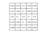
次いで本発明による画像処理方法の作用について説明する。図2は図1における多重解像度画像分解処理手段2において行われる処理を説明するためのブロック図である。なお、本実施の形態においてはラプラシアンピラミッドの手法により画像信号Sを多重解像度画像に分解するものとする。図2に示すように原画像を表すデジタルの画像信号Sが多重解像度分解処理手段2に入力されると、フィルタリング手段10においてローパスフィルタによりフィルタリングされる。このローパスフィルタは例えば図3に示すように5×5のグリッド上の二次元ガウス分布に略対応している。このローパスフィルタは後述するように全ての解像度の画像に対して適用される。
【0016】
このようなローパスフィルタによりフィルタリングされた画像信号Sはフィルタリング手段10において1画素おきにサンプリングされ、低解像度近似画像g1が得られる。この低解像度近似画像g1は、原画像の1/4の大きさとなっている。次いで補間手段11において、この低解像度近似画像g1のサンプリングされた間隔に値が0の画素が補間される。この補間は低解像度近似画像g1の列毎および一行毎に値が0の行および列を挿入することにより行う。このように値が0の画素が補間された低解像度近似画像g1はぼけてはいるものの一画素おきに値が0の画素が挿入されているため、信号値の変化が滑らかではないものとなっている。
【0017】
そしてこのようにして補間が行われた後、さらにこの補間がなされた低解像度近似画像g1に対して図3に示すローパスフィルタにより再度フィルタリング処理を施し、低解像度近似画像g1′を得る。この低解像度近似画像g1′上述した補間がなされた低解像度近似画像g1と比較して信号値の変化が滑らかなものとなっている。また原画像と比較して周波数帯域的には半分より高い高周波数が消えたような画像となっている。これは画像の大きさを1/4にして一画素おきに値が0の画素を補間し、さらに図3に示すローパスフィルタによりフィルタリング処理を施しているため、ガウス関数により空間周波数が半分よりも高い周波数帯域の画像がぼかされたようになっているからである。
【0018】
次いで減算器12において、原画像から低解像度近似画像g1′の減算が行われ、細部画像b0が得られる。この減算は原画像と低解像度近似画像g1′との相対応する画素についての信号間で行われる。ここで、低解像度近似画像g1′は上述したように原画像の空間周波数のうち半分より高い周波数帯域の画像がぼけたようになっているため、細部画像b0は原画像のうち半分より上の周波数帯域のみを表す画像となっている。すなわち、図4に示すように細部画像b0は原画像のナイキスト周波数NのうちN/2〜Nの周波数帯域の画像を表すものとなっている。
【0019】
次いで、低解像度近似画像g1はフィルタリング手段10に入力され、図3に示すローパスフィルタによりフィルタリング処理が施される。そしてフィルタリング処理が施された低解像度近似画像g1は、フィルタリング手段10において1画素おきにサンプリングされ、低解像度近似画像g2が得られる。この低解像度近似画像g2は、低解像度近似画像g1の1/4すなわち原画像の1/16の大きさとなっている。次いで補間手段11において、この低解像度近似画像g2のサンプリングされた間隔に値が0の画素が補間される。この補間は低解像度近似画像g2の一列毎および一行毎に値が0の行および列を挿入することにより行う。このように値が0の画素が補間された低解像度近似画像g2はぼけてはいるものの一画素おきに値が0の画素が挿入されているため、信号値の変化が滑らかではないものとなっている。
【0020】
そしてこのようにして補間が行われた後、さらにこの補間がなされた低解像度近似画像g2に対して図3に示すローパスフィルタにより再度フィルタリング処理を施し、低解像度近似画像g2′を得る。この低解像度近似画像g2′は上述した補間がなされた低解像度近似画像g2と比較して信号値の変化が滑らかなものとなっている。また低解像度近似画像g1と比較して周波数帯域的には半分より高い周波数帯域の画像が消えたようになっている。
【0021】
次いで減算器12において、低解像度近似画像g1から低解像度近似画像g2′の減算が行われ、細部画像b1が得られる。この減算は低解像度近似画像g1と低解像度近似画像g2′との相対応する画素についての信号間で行われる。ここで、低解像度近似画像g2′は上述したように低解像度近似画像g1の空間周波数のうち半分より高い周波数帯域の画像がぼけたようになっているため、細部画像b1は低解像度近似画像g1のうち半分より上の周波数帯域のみを表す画像となっている。すなわち、図4に示すように細部画像b1は低解像度近似画像g1のうちの半分より上の周波数帯域のみ、すなわち原画像のナイキスト周波数NのうちN/4〜N/2の周波数帯域の画像を表すものとなっている。このようにガウス分布のローパスフィルタによりフィルタリング処理を施して細部画像を得るようにしているが、フィルタリング処理が施された画像を低解像度近似画像から減算していることから、実質的にはラプラシアンフィルタによりフィルタリング処理を施した場合と同様の結果となる。
【0022】
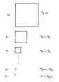
そして上述した処理をフィルタリング手段10によりフィルタリングされかつサンプリングされた低解像度近似画像gk(k=1〜N)に対して順次繰り返し行い、図4に示すようにn個の細部画像bk (k=1〜n)および低解像度近似画像の残留画像gLを得る。ここで、細部画像bkは、b0から順に解像度が低くなる、すなわち画像の周波数帯域が低くなるものであり、原画像のナイキスト周波数Nに対して、細部画像bkはN/2k+1〜N/2kの周波数帯域を表し、画像の大きさが原画像の1/22k倍となっている。すなわち、最も解像度が高い細部画像b0は原画像と同じ大きさであるが、細部画像b0の次に高解像度の細部画像b1原画像の大きさの1/4となっている。このように、細部画像が原画像と同一の大きさのものから順次小さくなり、また細部画像はラプラシアンフィルタを施したものと実質的に同一の画像であることから、本実施の形態による多重解像度変換はラプラシアンピラミッドと呼ばれるものである。また、残留画像gLは原画像の非常に解像度が低い近似画像であると見なすことができ、極端な場合は、残留画像gLは原画像の平均値を表す1つだけの画像からなるものとなる。そしてこのようにして得られた細部画像bkおよび残留画像gLは図示しないメモリに記憶される。
【0023】
次いでこのようにして得られた細部画像bkに対して強調処理手段3において強調処理が施される。以下強調処理の詳細について説明する。
【0024】
上述したように画像を多重解像度変換することにより得られる複数の周波数帯域ごとの細部画像bkにおいて、原画像に含まれる被写体の輪郭のような成分は、低周波数帯域の画像においてもある程度の大きさの信号値を有するものである。しかしながら、ノイズのような成分は高周波数帯域の画像には含まれるが、低周波数帯域の画像においては消えてしまい信号値としては0に近い値となる。例えば図5に示すように細部画像bkと細部画像bkよりも低周波数帯域の細部画像bk+1とを比較すると、点A,BおよびCにおいては双方の細部画像が信号値を有するものである。しかしながら点Dにおいては細部画像bkにおいては信号値を有するが、細部画像bk+1においては信号値が0となっている。したがって、細部画像bkの点Dはノイズのように不要な部分であり、他の点A,BおよびCは被写体の輪郭のように必要な部分であると見なすことができる。
【0025】
したがって、画像の強調を施す所定の周波数帯域よりも低周波数帯域の画像について、信号値の絶対値が比較的低い部分は所定の周波数帯域の画像のその部分に対応する部分が信号値を有するものであっても、その部分の信号により表される成分はノイズである可能性が非常に高い。よって、強調処理を施したい周波数帯域の細部画像bkよりも低周波数帯域の細部画像(本実施の形態においては1レベル周波数帯域が低い細部画像bk+1)の信号値を検出し、この信号値の検出の結果、細部画像bk+1における信号値の絶対値が比較的小さい部分に対応する細部画像bkの部分については、強調係数を他の部分と比較して小さくして強調を行うようにする。すなわち、図6に示すように細部画像bk+1の信号値の絶対値が大きいほど強調度fを大きくするものである。そしてこのようにして決定された細部画像bk+1に基づく強調度f(bk+1)を下記の式(1)に示すように細部画像bkに乗じ、強調画像bkpを得る。
【0026】
bkp=bk×f(bk+1) …(1)
このように所定周波数帯域の細部画像bkに対して強調処理を施すことにより、この所定周波数帯域の細部画像bkにおけるノイズ等の不要な成分は他の必要な成分よりも強調度が小さくなるため、目立たなくなる。
【0027】
なお、この強調処理において、細部画像bk+1の1つの画素に対応する点は細部画像bkにおいて4つある。このため、強調処理のための係数を決定する際には、細部画像bkの4つの画素に対応する細部画像bk+1の1つの画素値を補間して、4つの画素にそれぞれ対応する値を得、この値に基づいて強調係数を決定するものである。また、細部画像bkの4つの画素に対応する細部画像bk+11つの画素値を代表させて、この1つの画素値に基づいて4つの画素の強調度を決定するようにしてもよい。
【0028】
次いで、強調処理が施された周波数帯域の細部画像bkおよび他の周波数帯域の細部画像を逆変換する。この逆変換の処理は復元処理手段4において以下のようにして行われる。
【0029】
図7は細部画像の逆変換の詳細を表す図である。まず、残留画像gLが補間手段14により各画素の間が補間されて元の大きさの4倍の大きさの画像gL′とされる。次に加算器15においてその補間された画像gL′と最も低解像度の細部画像bn-1の相対応する画素同志で加算を行い、加算画像(gL′+bn-1)を得る。次いでこの加算画像(gL′+bn-1)は補間手段14に入力され、この補間手段14において各画素の間が補間されて元の大きさの4倍の大きさの画像bn-1´とされる。
【0030】
次いでこの画像bn-1′は、加算器15において細部画像bn-1の一段階高解像度の画像bn-2と相対応する画素同志の加算が行われ、加算された加算信号(bn-1′+bn-2)は補間手段14において各画素の間隔が補間され、細部画像bn-2の4倍の大きさの画像bn-2とされる。
【0031】
以上の処理を繰り返し、強調画像bkpについても同様の処理を施す。すなわち、強調画像bkpと上述した処理が施された一段階低解像度の画像bk-1′との加算が加算器15において行われ、さらに加算信号(bkp+bk-1′)に対して補間手段14において各画素の間が補間され、補間信号bkp′を得る。そしてこの処理をより高周波の細部画像に対して順次行い、最終的に加算器15において補間画像b1′と最高解像度の細部画像b0との加算が行われ、処理済画像信号S′を得る。
【0032】
このようにして得られた処理済画像信号S′は画像出力手段5に入力され、可視像として表示される。この画像出力手段5はCRT等のディスプレイ手段でもよいし、感光フィルムに光走査記録を行う記録装置であってもよいし、あるいはそのために画像信号を一旦光ディスク、磁気ディスク等の画像ファイルに記憶させる装置であってもよい。
【0033】
このようにしてラプラシアンピラミッドにより多重解像度に変換された細部画像に対して、所望とする周波数帯域の細部画像に対する強調係数をその所望とする周波数帯域よりも低周波数帯域の細部画像の信号に基づいて設定することにより、所望と周波数帯域の画像はノイズ等の不要な成分はそれ程強調されることなく、被写体の輪郭等の必要な成分のみが強調されることとなる。したがって、強調処理が施された細部画像およびそれ以外の細部画像を逆変換することにより得られる処理済画像は、所望とする周波数帯域の画像が強調されているが、この周波数帯域におけるノイズ等の不要な部分は強調されていないため、ノイズが目立たない観察読影に適した良好なものとなる。
【0034】
なお、上述した実施の形態においては、画像を多重解像度画像に変換するためにラプラシアンピラミッドの手法を用いているが、これに限定されるものではなく、例えばウェーブレット変換、あるいはサブバンド変換等他の方法により多重解像度画像に変換するようにしてもよいものである。
【0035】
ここで、ウェーブレット変換は、周波数解析の方法として近年開発されたものであり、ステレオのパターンマッチング、データ圧縮等に応用がなされているものである(OLIVIER RIOUL and MARTIN VETTERLI;Wavelets and Signal Processing,IEEE SP MAGAZINE,P.14-38,OCTOBER 1991、Stephane Mallat;Zero-Crossings of a Wavelet Transform,IEEE TRANSACTIONS ON INFORMATION THEORY,VOL.37,NO.4,P.1019-1033,JULY 1991 )。
【0036】
このウェーブレット変換は、
【0037】
【数1】
なる式において信号を複数の周波数帯域ごとの周波数信号に変換するものである。すなわち、関数hの周期および縮率を変化させ、原信号を移動させることによりフィルタリング処理を行えば、細かな周波数から粗い周波数までの所望とする周波数に適合した周波数信号を作成することができる。
【0039】
一方、サブバンド変換は、ウェーブレット変換のように1種類のフィルタにより2つの周波数帯域の画像を得るのみではなく、複数種類のフィルタを用いて複数の周波数帯域の画像を一度に得ることをも含む変換方法である。
【0040】
そして、このようにウェーブレット変換あるいはサブバンド変換により得られた複数の周波数帯域ごとの画像に対して上述したラプラシアンピラミッドの場合と同様に、所望とする周波数帯域の画像に対してこの周波数帯域よりも低周波数帯域の画像の信号値に基づいて強調係数を設定して強調処理を行うことにより、所望とする周波数帯域の画像が強調されるが、この周波数帯域におけるノイズ等の不要な部分は強調されないため、ノイズが目立たない観察読影に適した良好な画像を得ることができる。
【0041】
また、上述した実施の形態においては強調処理を施す所望とする周波数帯域の画像の強調係数をその周波数帯域よりも一段階低周波数帯域の画像の信号値に基づいて決定するようにしているが、一段階低周波数帯域のみではなく、二段階、三段階あるいはそれ以上低周波数帯域の画像に基づいて決定するようにしてもよいものである。
【図面の簡単な説明】
【図1】本発明による画像処理方法を実施するための装置のブロック図
【図2】多重解像度分解処理手段の詳細を表す図
【図3】ローパスフィルタを表す図
【図4】ラプラシアンピラミッドが施された複数の周波数帯域ごとの細部画像を表す図
【図5】細部画像bkおよび細部画像bk+1の比較図
【図6】強調度を表すグラフ
【図7】復元処理手段の詳細を表す図
【符号の説明】
1 画像入力手段
2 多重解像度分解処理手段
3 強調処理手段
4 復元処理手段
5 画像出力手段
10 フィルタリング手段
11 補間手段
12 減算器
14 補間手段
15 加算器[0001]
BACKGROUND OF THE INVENTION
The present invention relates to an image processing method and apparatus for performing image processing on a predetermined frequency band in an original image.
[0002]
[Prior art]
In various fields, an image signal representing an image is obtained, and an appropriate image process is performed on the image signal, and then the image is reproduced and displayed. For example, in order to improve the diagnostic performance of a radiographic image, a method of performing frequency enhancement processing such as blur mask processing on an image signal has been proposed by the present applicant (Japanese Patent Laid-Open No. Sho 55-163772). This frequency processing is a process for adding a signal obtained by subtracting a blur mask signal from an image signal representing an original image and multiplying the degree of enhancement, thereby enhancing a predetermined spatial frequency component in the image. is there.
[0003]
As another method for performing frequency processing on an image signal, an image signal representing an image is converted into a signal of a plurality of frequency bands by converting the image into a multi-resolution image by Fourier transform, wavelet transform, subband transform, or the like. There has been proposed a method of performing decomposition and performing predetermined image processing such as enhancement on a signal in a desired frequency band among the decomposed signals.
[0004]
In recent years, in the field of image processing, a Laplacian pyramid method has been proposed as a new method for converting an image into multiple resolutions (for example, JP-A-6-301766). This Laplacian pyramid is obtained by masking an original image with a mask approximated by a Gaussian function and then sub-sampling the image to thin out the number of pixels and halve the original image. A blurred image of the size is obtained, a pixel with a value of 0 is interpolated into the sampled pixels of this blurred image to return to the original size image, and this image is further subjected to mask processing using the mask described above. A blurred image is obtained, and the blurred image is subtracted from the original image to obtain a detailed image of a predetermined frequency band of the original image. By repeating this process for the blurred image obtained, N blurred images having a size of 1 /22N of the original image are created. Here, since sampling is performed on an image masked with a mask approximated by a Gaussian function, a Gaussian filter is actually used, but the same processing as when a Laplacian filter is applied An image is obtained. Since images in the low frequency band of 1 /22N are obtained sequentially from the original image size in this way, the image obtained as a result of this processing is called a Laplacian pyramid.
[0005]
For this Laplacian pyramid, see Burt PJ, “Fast Filter Transforms for Image Processing”, Computer Graphics and Image Processing, Volume 16, pp. 20-51, 1981; Crowley JL, Stern RM, “Fast Computation of the Difference of Low・ Pass Transform “IEEE Trans.on Pattern Analysis and Machine Intelligence, Vol. 6, No. 2, March 1984, Mallat SG,“ A Theory for Multiresolution Signal Decomposition; The Wavelet Representation ”IEEE Trans.on Pattern Analysis and Machine Intelligence, 11 Vol. 7, No. 7, July 1989; Ebrahimi T., Kunt M., “Image compression by Gabor Expansion”, Optical Engineering, Vol. 30, No. 7, pages 873-880, July 1991, and Pieter Vuylsteke, Emile Details are described in Schoeters, “Multiscale Image Contrast Amplification” SPIEVol.2167 Image Processing (1994), pp 551-560.
[0006]
Then, the image of all frequency bands of the Laplacian pyramid thus obtained is subjected to a process for enhancing the image value, and the image of each frequency band subjected to the enhancement process is inversely transformed. A method for obtaining a processed image is described in the above-mentioned JP-A-6-301766. Since the image thus processed is emphasized in each frequency band, the image is substantially an image obtained by performing the blur mask process with a plurality of mask sizes in the blur mask process described above.
[0007]
[Problems to be solved by the invention]
However, in the method described in Japanese Patent Laid-Open No. 6-301766, when emphasis processing is performed on an image in a certain frequency band, noise and the like are included along with components such as the contour of the subject that needs emphasis processing in the image. Since unnecessary components are also emphasized, the image obtained as a result of the processing also emphasizes other noise components such as the contour of the subject. For this reason, the image obtained as a result of image processing is conspicuous in noise and difficult to see.
[0008]
In view of the above circumstances, an object of the present invention is to provide an image processing method and apparatus capable of emphasizing only necessary components in an image and obtaining a high-quality processed image.
[0009]
[Means for Solving the Problems]
An image processing method and apparatus according to the present invention decomposes an image into a plurality of frequency band images by converting the image into a multi-resolution space,
For an image in a predetermined frequency band among the plurality of frequency bands, enhancement corresponding to a portion having a relatively large absolute value of a signal value in an image in a frequency band lower than the predetermined frequency band has a higher enhancement degree. Multiply by a factor
A processed image is obtained by performing inverse multi-resolution conversion on an image in a frequency band multiplied by the enhancement coefficient and an image in another frequency band.
[0010]
Here, the conversion to the multi-resolution space means that an image signal is decomposed into images for each of a plurality of frequency bands by a predetermined filter such as a Laplacian pyramid, a wavelet transform, and a subband transform.
[0011]
【The invention's effect】
In an image for each of a plurality of frequency bands obtained when the image is converted by multi-resolution conversion, a component such as a contour of a subject included in the original image is also included in the component of the image in a low frequency band image. It is. However, components such as noise are included in an image in a high frequency band, but are not included in an image in a relatively low frequency band. Therefore, in an image in a frequency band lower than a predetermined frequency band where image enhancement is performed, a portion where the absolute value of the signal value is relatively low has a signal value in a portion corresponding to that portion of the image in the predetermined frequency band Even if it is a thing, the component of the image represented by the signal of the part is very likely to be noise. For this reason, when emphasis processing is performed on the entire image in a predetermined frequency band, not only a necessary component like a subject but also an unnecessary component such as noise is emphasized. The present invention has been made in view of this point.
[0012]
That is, in the image processing method and apparatus according to the present invention, an absolute value of a signal value in an image in a frequency band lower than a predetermined frequency band to which enhancement processing is performed among images in a plurality of frequency bands converted into a multi-resolution space. The degree of enhancement of the image portion of the predetermined frequency band corresponding to this portion is increased as the portion is relatively large. As a result, a portion where the absolute value of the signal value in the image in the low frequency band that can be regarded as noise in the predetermined frequency band is relatively small is less enhanced than the other portions. By performing enhancement processing on an image in a predetermined frequency band in this manner, unnecessary components such as noise in the image in the predetermined frequency band are less emphasized than necessary components such as other subjects. Disappear. Therefore, the processed image obtained by inversely transforming the image of the frequency band subjected to the enhancement process and the image of the other frequency band, the unnecessary components such as noise among the components of the predetermined frequency band are not noticeable, It is possible to obtain a high-quality image in which components such as a necessary subject outline are emphasized.
[0013]
DETAILED DESCRIPTION OF THE INVENTION
Embodiments of the present invention will be described below with reference to the drawings.
[0014]
FIG. 1 is a block diagram showing an outline of an apparatus for carrying out an image processing method according to the present invention. As shown in FIG. 1, an apparatus for carrying out an image processing method according to the present invention includes an image input means 1 for inputting an image into the apparatus, and a multi-resolution decomposition for performing a multi-resolution decomposition process on the input image. Processing means 2, enhancement processing means 3 for performing enhancement processing as described later on an image of a predetermined frequency band among images decomposed into a plurality of frequency bands by the multi-resolution decomposition processing means 2, and enhancement processing means The restoration processing means 4 for obtaining the processed image by restoring the frequency band image and the other frequency band image subjected to the emphasis processing by 3 and the processed image restored by the restoration processing means 4 are visible. It comprises image output means 5 for reproducing as an image.
[0015]
Next, the operation of the image processing method according to the present invention will be described. FIG. 2 is a block diagram for explaining processing performed in the multi-resolution image decomposition processing means 2 in FIG. In the present embodiment, it is assumed that the image signal S is decomposed into multi-resolution images by a Laplacian pyramid technique. As shown in FIG. 2, when a digital image signal S representing an original image is input to the multiresolution decomposition processing means 2, the filtering means 10 filters it with a low-pass filter. This low-pass filter substantially corresponds to a two-dimensional Gaussian distribution on a 5 × 5 grid as shown in FIG. 3, for example. This low-pass filter is applied to images of all resolutions as will be described later.
[0016]
Such low-pass image signals filtered by the filters S is sampled every other pixel in the filtering means 10, the low-resolution approximate image g1 is obtained. This low resolution approximate image g1 is ¼ the size of the original image. Then the interpolation means 11, the pixel values in the low-resolution approximate image g1 sampled
[0017]
Then, after the interpolation is performed in this way, the low resolution approximate image g1 subjected to the interpolation is again subjected to the filtering process by the low pass filter shown in FIG. 3 to obtain the low resolution approximate image g1 ′. This low-resolution approximate image g1 ′ has a smoother signal value change than the low-resolution approximate image g1 subjected to the above-described interpolation. Also, the image is such that the high frequency higher than half of the frequency band disappears compared to the original image. This is because the size of the image is set to ¼, and pixels with a value of 0 are interpolated every other pixel, and further, filtering processing is performed by the low pass filter shown in FIG. 3, so the spatial frequency is less than half by the Gaussian function. This is because an image in a high frequency band is blurred.
[0018]
Next, the
[0019]
Next, the low resolution approximate image g1 is input to the filtering means 10 and subjected to filtering processing by a low pass filter shown in FIG. Then, the low resolution approximate image g1 subjected to the filtering process is sampled every other pixel by the filtering means 10 to obtain a low resolution approximate image g2 . The low-resolution approximate image g2 is 1/4 the size of the low-resolution approximate image g1 , that is, 1/16 of the original image. Then the interpolation means 11, the pixel values in the low-resolution approximate image g2 sampled
[0020]
Then, after the interpolation is performed in this way, the low resolution approximate image g2 subjected to the interpolation is again subjected to the filtering process by the low pass filter shown in FIG. 3 to obtain the low resolution approximate image g2 ′. This low-resolution approximate image g2 ′ has a smooth signal value change as compared with the low-resolution approximate image g2 subjected to the above-described interpolation. Further, compared to the low-resolution approximate image g1 , an image in a frequency band higher than half of the frequency band disappears.
[0021]
Then, in the
[0022]
Then, the above-described processing is sequentially repeated on the low-resolution approximate images gk (k = 1 to N) filtered and sampled by the filtering means 10, and as shown in FIG. 4, n detailed images bk ( k = 1 to n) and the residual image gL of the low resolution approximate image. Here, the detail image bk has a resolution that decreases in order from b0 , that is, the frequency band of the image decreases, and the detail image bk is N / 2k + with respect to the Nyquist frequency N of the original image. represents the frequency band of1 ~N / 2k, the size of the image is a 1/22k times the original image. That is, the detail image b0 having the highest resolution is the same size as the original image, but is ¼ of the size of the detail image b1 of the high resolution next to the detail image b0 . As described above, since the detail image is sequentially reduced from the same size as the original image, and the detail image is substantially the same image as that subjected to the Laplacian filter, the multiple resolution according to the present embodiment The transformation is called the Laplacian pyramid. Further, the residual image gL can be regarded as an approximate image with a very low resolution of the original image. In an extreme case, the residual image gL is composed of only one image representing the average value of the original image. It becomes. The detailed image bk and the residual image gL thus obtained are stored in a memory (not shown).
[0023]
Next, enhancement processing means 3 performs enhancement processing on the detailed image bk obtained in this way. Details of the emphasis process will be described below.
[0024]
As described above, in the detail image bk for each of a plurality of frequency bands obtained by multi-resolution conversion of the image, components such as the contour of the subject included in the original image have a certain size even in the low frequency band image. Signal value. However, although components such as noise are included in the high frequency band image, they disappear in the low frequency band image, and the signal value is close to zero. Having for example than the detail image bk and detail image bk as shown in FIG. 5 is compared with the detail image bk + 1 of the low frequency band, the point A, both detail image in the B and C signal values Is. However, at the point D, the detail image bk has a signal value, but the detail image bk + 1 has a signal value of 0. Therefore, the point D of the detailed image bk is an unnecessary part such as noise, and the other points A, B, and C can be regarded as necessary parts such as the contour of the subject.
[0025]
Therefore, for an image in a frequency band lower than a predetermined frequency band to which image enhancement is performed, a portion where the absolute value of the signal value is relatively low has a signal value in a portion corresponding to that portion of the image in the predetermined frequency band Even so, the component represented by the signal in that portion is very likely to be noise. Therefore, the signal value of the detail image in the lower frequency band (in this embodiment, the detail image bk + 1 having a lower one-level frequency band) than the detail image bk in the frequency band to be enhanced is detected. result of the detection of the signal values, parts of the detail image bk of the absolute value of the signal values in the detail image bk + 1 corresponds to a relatively small portion, and smaller than the emphasis coefficient with other portions highlighted To do. That is, as shown in FIG. 6, the degree of enhancement f is increased as the absolute value of the signal value of the detailed image bk + 1 increases. Then, the enhancement image bkp is obtained by multiplying the detail image bk by the enhancement degree f (bk + 1 ) based on the detail image bk + 1 determined in this way as shown in the following equation (1).
[0026]
bkp = bk × f (bk + 1 ) (1)
By performing enhancement processing on the detailed image bk in the predetermined frequency band in this way, unnecessary components such as noise in the detailed image bk in the predetermined frequency band are less enhanced than other necessary components. Therefore, it will not stand out.
[0027]
In this enhancement processing, there are four points in the detail image bk corresponding to one pixel of the detail image bk + 1 . Therefore, in determining the coefficients for enhancement processing interpolates a pixel value of the detail image bk + 1 corresponding to the four pixels of the detail images bk, respectively corresponding to four pixels A value is obtained, and an enhancement coefficient is determined based on this value. Further, as a representative of the detail images bk + 1 one pixel value corresponding to the four pixels of the detail images bk, may be determined enhancement degree of the four pixels on the basis of this one pixel value .
[0028]
Next, the detail image bk in the frequency band subjected to the enhancement process and the detail image in the other frequency band are inversely transformed. This inverse transformation process is performed in the restoration processing means 4 as follows.
[0029]
FIG. 7 is a diagram showing details of inverse transformation of a detail image. First, the residual image gL is interpolated between the pixels by the interpolation means 14 to obtain an image gL ′ having a size four times the original size. Next, the
[0030]
Next, the image bn-1 ′ is subjected to addition of pixels corresponding to the one-step high-resolution image bn-2 of the detail image bn-1 in the
[0031]
The above processing is repeated, and the same processing is performed for the emphasized image bkp . That is, the addition of the enhanced image bkp and the one-step low-resolution image bk−1 ′ subjected to the above-described processing is performed in the
[0032]
The processed image signal S ′ thus obtained is input to the image output means 5 and displayed as a visible image. The image output means 5 may be a display means such as a CRT, or may be a recording device that performs optical scanning recording on a photosensitive film, or for this purpose, an image signal is temporarily stored in an image file such as an optical disk or a magnetic disk. It may be a device.
[0033]
For the detail image converted to multi-resolution by the Laplacian pyramid in this way, the enhancement coefficient for the detail image in the desired frequency band is based on the signal of the detail image in the lower frequency band than the desired frequency band. By setting, an image in the desired and frequency bands is emphasized only for necessary components such as the contour of the subject without emphasizing unnecessary components such as noise. Therefore, the processed image obtained by inversely transforming the detail image subjected to the enhancement process and the other detail images is enhanced in the image of the desired frequency band. Since unnecessary portions are not emphasized, it is suitable for observation interpretation in which noise is not noticeable.
[0034]
In the above-described embodiment, the Laplacian pyramid method is used to convert an image into a multi-resolution image. However, the present invention is not limited to this. For example, other methods such as wavelet conversion or subband conversion are used. It may be converted into a multi-resolution image by a method.
[0035]
Wavelet transform, which was recently developed as a frequency analysis method, has been applied to stereo pattern matching, data compression, etc. (OLIVIER RIOUL and MARTIN VETTERLI; Wavelets and Signal Processing, IEEE SP MAGAZINE, P.14-38, OCTOBER 1991, Stephane Mallat; Zero-Crossings of a Wavelet Transform, IEEE TRANSACTIONS ON INFORMATION THEORY, VOL.37, NO.4, P.1019-1033, JULY 1991).
[0036]
This wavelet transform
[0037]
[Expression 1]
In this equation, the signal is converted into a frequency signal for each of a plurality of frequency bands. That is, if the filtering process is performed by changing the period and the reduction ratio of the function h and moving the original signal, a frequency signal suitable for a desired frequency from a fine frequency to a coarse frequency can be created.
[0039]
On the other hand, the subband transformation includes not only obtaining images of two frequency bands by one type of filter as in the case of wavelet transformation, but also obtaining images of a plurality of frequency bands at once using a plurality of types of filters. It is a conversion method.
[0040]
As in the case of the Laplacian pyramid described above for an image for each of a plurality of frequency bands obtained by wavelet transform or subband transform in this way, an image of a desired frequency band is more than this frequency band. By performing enhancement processing by setting an enhancement coefficient based on the signal value of the image in the low frequency band, the image in the desired frequency band is enhanced, but unnecessary portions such as noise in this frequency band are not enhanced. Therefore, it is possible to obtain a good image suitable for observation interpretation in which noise is not noticeable.
[0041]
Further, in the above-described embodiment, the enhancement coefficient of an image in a desired frequency band on which enhancement processing is performed is determined based on the signal value of the image in a lower frequency band than that frequency band. The determination may be based not only on the one-stage low frequency band but also on the two-stage, three-stage or more low-frequency band images.
[Brief description of the drawings]
FIG. 1 is a block diagram of an apparatus for carrying out an image processing method according to the present invention. FIG. 2 is a diagram showing details of multi-resolution decomposition processing means. FIG. 3 is a diagram showing a low-pass filter. FIG. 5 is a diagram representing a detail image for each of a plurality of frequency bands. FIG. 5 is a comparison diagram between detail image bk and detail image bk + 1. FIG. 6 is a graph representing a degree of enhancement. Representation [Explanation of symbols]
DESCRIPTION OF
10 Filtering means
11 Interpolation means
12 Subtractor
14 Interpolation means
15 Adder
Claims (2)
Translated fromJapanese該複数の周波数帯域のうち所定の周波数帯域の細部画像に対して、該所定の周波数帯域よりも低周波数帯域の細部画像における信号値の絶対値が比較的大きい部分に対応する部分ほど大きい強調度の強調係数を乗じ、
前記残留画像、該強調係数が乗じられた周波数帯域の細部画像および他の周波数帯域の細部画像を逆多重解像度変換することにより処理済画像を得ることを特徴とする画像処理方法。By transforming the image into a multi-resolution space, the image is decomposed into adetail image for each of a plurality of frequency bandsand a residual imagethat is a minimum resolution approximate image ,
For adetail image in a predetermined frequency band among the plurality of frequency bands, the degree of enhancement that is greater in a portion corresponding to a portion where the absolute value of a signal value ina detail image in a lower frequency band than the predetermined frequency band is relatively large Multiply by the enhancement factor of
Image processing method characterized by obtaining a processed image bythe residual image, the inverse multi-resolution transform thedetail imagesdetail images and other frequency bands of the frequency band is multiplied by the said strong tone factor.
該複数の周波数帯域のうち所定の周波数帯域の細部画像に対して、該所定の周波数帯域よりも低周波数帯域の細部画像における信号値の絶対値が比較的大きい部分に対応する部分ほど大きい強調度の強調係数を乗じる強調係数乗算手段と、
前記残留画像、該強調係数が乗じられた周波数帯域の細部画像および他の周波数帯域の細部画像を逆多重解像度変換することにより処理済画像を得る逆変換手段とからなることを特徴とする画像処理装置。Image decomposition means for converting the image into a multi-resolution space to decompose the image into adetail image for each of a plurality of frequency bandsand a residual imagethat is a minimum resolution approximate image ;
For adetail image in a predetermined frequency band among the plurality of frequency bands, the degree of enhancement that is greater in a portion corresponding to a portion where the absolute value of a signal value ina detail image in a lower frequency band than the predetermined frequency band is relatively large Enhancement factor multiplication means for multiplying the enhancement factor by
An image processing comprising: the residual image, adetail image in a frequency band multiplied by theenhancement coefficient, and an inverse transform means for obtaining a processed image by performing inverse multi-resolution transform on thedetail image in another frequency band apparatus.
Priority Applications (2)
| Application Number | Priority Date | Filing Date | Title |
|---|---|---|---|
| JP19151895AJP4004561B2 (en) | 1995-07-27 | 1995-07-27 | Image processing method and apparatus |
| US08/685,613US5907642A (en) | 1995-07-27 | 1996-07-24 | Method and apparatus for enhancing images by emphasis processing of a multiresolution frequency band |
Applications Claiming Priority (1)
| Application Number | Priority Date | Filing Date | Title |
|---|---|---|---|
| JP19151895AJP4004561B2 (en) | 1995-07-27 | 1995-07-27 | Image processing method and apparatus |
Publications (2)
| Publication Number | Publication Date |
|---|---|
| JPH0944655A JPH0944655A (en) | 1997-02-14 |
| JP4004561B2true JP4004561B2 (en) | 2007-11-07 |
Family
ID=16275996
Family Applications (1)
| Application Number | Title | Priority Date | Filing Date |
|---|---|---|---|
| JP19151895AExpired - LifetimeJP4004561B2 (en) | 1995-07-27 | 1995-07-27 | Image processing method and apparatus |
Country Status (1)
| Country | Link |
|---|---|
| JP (1) | JP4004561B2 (en) |
Families Citing this family (11)
| Publication number | Priority date | Publication date | Assignee | Title |
|---|---|---|---|---|
| JP3750776B2 (en)* | 1998-03-26 | 2006-03-01 | 富士写真フイルム株式会社 | Image sharpness estimation method and apparatus |
| JP4001457B2 (en)* | 2000-11-24 | 2007-10-31 | 富士フイルム株式会社 | Multi-resolution conversion method and apparatus, and recording medium |
| US7567254B2 (en) | 2005-06-30 | 2009-07-28 | Microsoft Corporation | Parallel texture synthesis having controllable jitter |
| US7477794B2 (en) | 2005-06-30 | 2009-01-13 | Microsoft Corporation | Multi-level image stack of filtered images |
| US7400330B2 (en) | 2005-06-30 | 2008-07-15 | Microsoft Corporation | Magnification of indirection textures |
| US8068117B2 (en) | 2005-06-30 | 2011-11-29 | Microsoft Corporation | Parallel texture synthesis by upsampling pixel coordinates |
| US7817160B2 (en) | 2005-06-30 | 2010-10-19 | Microsoft Corporation | Sub-pass correction using neighborhood matching |
| US7817161B2 (en) | 2006-06-26 | 2010-10-19 | Microsoft Corporation | Texture synthesis using dimensionality-reduced appearance space |
| US7733350B2 (en) | 2006-06-30 | 2010-06-08 | Microsoft Corporation | Anisometric texture synthesis |
| US7643034B2 (en) | 2006-06-30 | 2010-01-05 | Microsoft Corporation | Synthesis of advecting texture using adaptive regeneration |
| CN106331429A (en)* | 2016-08-31 | 2017-01-11 | 上海交通大学 | A video detail amplification method |
- 1995
- 1995-07-27JPJP19151895Apatent/JP4004561B2/ennot_activeExpired - Lifetime
Also Published As
| Publication number | Publication date |
|---|---|
| JPH0944655A (en) | 1997-02-14 |
Similar Documents
| Publication | Publication Date | Title |
|---|---|---|
| JP4004562B2 (en) | Image processing method and apparatus | |
| Eslami et al. | Translation-invariant contourlet transform and its application to image denoising | |
| Jiji et al. | Single‐frame image super‐resolution using learned wavelet coefficients | |
| JP4203980B2 (en) | Data processing method and apparatus, and recording medium | |
| US6005983A (en) | Image enhancement by non-linear extrapolation in frequency space | |
| US5907642A (en) | Method and apparatus for enhancing images by emphasis processing of a multiresolution frequency band | |
| JP3675896B2 (en) | Image processing method and apparatus | |
| JP3700804B2 (en) | Image processing method and apparatus | |
| JP2002269556A (en) | Method for removing noise from digital image based on multiresolution | |
| JPH06245113A (en) | Equipment for improving picture still more by removing noise and other artifact | |
| CN101295399A (en) | Resolution enhancement device and method | |
| JPH02503241A (en) | Digital image noise suppression method using SVD block transform | |
| JP4004561B2 (en) | Image processing method and apparatus | |
| JP2000216682A (en) | Signal processor and signal processing method | |
| Lakshman et al. | Image interpolation using shearlet based iterative refinement | |
| JPH09212623A (en) | Image processing method | |
| Witwit et al. | Global motion based video super-resolution reconstruction using discrete wavelet transform | |
| JP2001167264A (en) | Method and device for image processing and recording medium | |
| JPH0944651A (en) | Image processing method and device therefor | |
| JP4014671B2 (en) | Multi-resolution conversion method and apparatus | |
| JP2002074356A (en) | Method and device for processing picture and recording medium | |
| JPH09161061A (en) | Image processing method and processor therefor | |
| JP3788031B2 (en) | Image processing method and image processing apparatus | |
| JP2007188211A (en) | Image processing apparatus, imaging apparatus, image processing method and program thereof | |
| Rohith et al. | A novel approach to super resolution image reconstruction algorithm from low resolution panchromatic images |
Legal Events
| Date | Code | Title | Description |
|---|---|---|---|
| A977 | Report on retrieval | Free format text:JAPANESE INTERMEDIATE CODE: A971007 Effective date:20040827 | |
| A131 | Notification of reasons for refusal | Free format text:JAPANESE INTERMEDIATE CODE: A131 Effective date:20040907 | |
| A02 | Decision of refusal | Free format text:JAPANESE INTERMEDIATE CODE: A02 Effective date:20050426 | |
| A521 | Written amendment | Free format text:JAPANESE INTERMEDIATE CODE: A523 Effective date:20050525 | |
| A911 | Transfer of reconsideration by examiner before appeal (zenchi) | Free format text:JAPANESE INTERMEDIATE CODE: A911 Effective date:20050627 | |
| A912 | Removal of reconsideration by examiner before appeal (zenchi) | Free format text:JAPANESE INTERMEDIATE CODE: A912 Effective date:20050930 | |
| A711 | Notification of change in applicant | Free format text:JAPANESE INTERMEDIATE CODE: A712 Effective date:20061128 | |
| A61 | First payment of annual fees (during grant procedure) | Free format text:JAPANESE INTERMEDIATE CODE: A61 Effective date:20070822 | |
| R150 | Certificate of patent (=grant) or registration of utility model | Free format text:JAPANESE INTERMEDIATE CODE: R150 | |
| FPAY | Renewal fee payment (prs date is renewal date of database) | Free format text:PAYMENT UNTIL: 20100831 Year of fee payment:3 | |
| FPAY | Renewal fee payment (prs date is renewal date of database) | Free format text:PAYMENT UNTIL: 20110831 Year of fee payment:4 | |
| FPAY | Renewal fee payment (prs date is renewal date of database) | Free format text:PAYMENT UNTIL: 20110831 Year of fee payment:4 | |
| FPAY | Renewal fee payment (prs date is renewal date of database) | Free format text:PAYMENT UNTIL: 20120831 Year of fee payment:5 | |
| FPAY | Renewal fee payment (prs date is renewal date of database) | Free format text:PAYMENT UNTIL: 20120831 Year of fee payment:5 | |
| FPAY | Renewal fee payment (prs date is renewal date of database) | Free format text:PAYMENT UNTIL: 20130831 Year of fee payment:6 | |
| R250 | Receipt of annual fees | Free format text:JAPANESE INTERMEDIATE CODE: R250 | |
| R250 | Receipt of annual fees | Free format text:JAPANESE INTERMEDIATE CODE: R250 | |
| EXPY | Cancellation because of completion of term |