JP4003446B2 - Bearing device - Google Patents
Bearing deviceDownload PDFInfo
- Publication number
- JP4003446B2 JP4003446B2JP2001359383AJP2001359383AJP4003446B2JP 4003446 B2JP4003446 B2JP 4003446B2JP 2001359383 AJP2001359383 AJP 2001359383AJP 2001359383 AJP2001359383 AJP 2001359383AJP 4003446 B2JP4003446 B2JP 4003446B2
- Authority
- JP
- Japan
- Prior art keywords
- shaft body
- flange
- shaft
- inner ring
- press
- Prior art date
- Legal status (The legal status is an assumption and is not a legal conclusion. Google has not performed a legal analysis and makes no representation as to the accuracy of the status listed.)
- Expired - Fee Related
Links
Images


Classifications
- F—MECHANICAL ENGINEERING; LIGHTING; HEATING; WEAPONS; BLASTING
- F16—ENGINEERING ELEMENTS AND UNITS; GENERAL MEASURES FOR PRODUCING AND MAINTAINING EFFECTIVE FUNCTIONING OF MACHINES OR INSTALLATIONS; THERMAL INSULATION IN GENERAL
- F16C—SHAFTS; FLEXIBLE SHAFTS; ELEMENTS OR CRANKSHAFT MECHANISMS; ROTARY BODIES OTHER THAN GEARING ELEMENTS; BEARINGS
- F16C19/00—Bearings with rolling contact, for exclusively rotary movement
- F16C19/02—Bearings with rolling contact, for exclusively rotary movement with bearing balls essentially of the same size in one or more circular rows
- F16C19/14—Bearings with rolling contact, for exclusively rotary movement with bearing balls essentially of the same size in one or more circular rows for both radial and axial load
- F16C19/18—Bearings with rolling contact, for exclusively rotary movement with bearing balls essentially of the same size in one or more circular rows for both radial and axial load with two or more rows of balls
- F16C19/181—Bearings with rolling contact, for exclusively rotary movement with bearing balls essentially of the same size in one or more circular rows for both radial and axial load with two or more rows of balls with angular contact
- F16C19/183—Bearings with rolling contact, for exclusively rotary movement with bearing balls essentially of the same size in one or more circular rows for both radial and axial load with two or more rows of balls with angular contact with two rows at opposite angles
- F16C19/184—Bearings with rolling contact, for exclusively rotary movement with bearing balls essentially of the same size in one or more circular rows for both radial and axial load with two or more rows of balls with angular contact with two rows at opposite angles in O-arrangement
- F16C19/185—Bearings with rolling contact, for exclusively rotary movement with bearing balls essentially of the same size in one or more circular rows for both radial and axial load with two or more rows of balls with angular contact with two rows at opposite angles in O-arrangement with two raceways provided integrally on a part other than a race ring, e.g. a shaft or housing
- F—MECHANICAL ENGINEERING; LIGHTING; HEATING; WEAPONS; BLASTING
- F16—ENGINEERING ELEMENTS AND UNITS; GENERAL MEASURES FOR PRODUCING AND MAINTAINING EFFECTIVE FUNCTIONING OF MACHINES OR INSTALLATIONS; THERMAL INSULATION IN GENERAL
- F16C—SHAFTS; FLEXIBLE SHAFTS; ELEMENTS OR CRANKSHAFT MECHANISMS; ROTARY BODIES OTHER THAN GEARING ELEMENTS; BEARINGS
- F16C33/00—Parts of bearings; Special methods for making bearings or parts thereof
- F16C33/30—Parts of ball or roller bearings
- F16C33/58—Raceways; Race rings
- F16C33/588—Races of sheet metal
- F—MECHANICAL ENGINEERING; LIGHTING; HEATING; WEAPONS; BLASTING
- F16—ENGINEERING ELEMENTS AND UNITS; GENERAL MEASURES FOR PRODUCING AND MAINTAINING EFFECTIVE FUNCTIONING OF MACHINES OR INSTALLATIONS; THERMAL INSULATION IN GENERAL
- F16C—SHAFTS; FLEXIBLE SHAFTS; ELEMENTS OR CRANKSHAFT MECHANISMS; ROTARY BODIES OTHER THAN GEARING ELEMENTS; BEARINGS
- F16C2326/00—Articles relating to transporting
- F16C2326/01—Parts of vehicles in general
- F16C2326/02—Wheel hubs or castors
- F—MECHANICAL ENGINEERING; LIGHTING; HEATING; WEAPONS; BLASTING
- F16—ENGINEERING ELEMENTS AND UNITS; GENERAL MEASURES FOR PRODUCING AND MAINTAINING EFFECTIVE FUNCTIONING OF MACHINES OR INSTALLATIONS; THERMAL INSULATION IN GENERAL
- F16C—SHAFTS; FLEXIBLE SHAFTS; ELEMENTS OR CRANKSHAFT MECHANISMS; ROTARY BODIES OTHER THAN GEARING ELEMENTS; BEARINGS
- F16C41/00—Other accessories, e.g. devices integrated in the bearing not relating to the bearing function as such
- F16C41/007—Encoders, e.g. parts with a plurality of alternating magnetic poles
Landscapes
- Engineering & Computer Science (AREA)
- General Engineering & Computer Science (AREA)
- Mechanical Engineering (AREA)
- Support Of The Bearing (AREA)
- Mounting Of Bearings Or Others (AREA)
- Rolling Contact Bearings (AREA)
Description
Translated fromJapanese【0001】
【発明の属する技術分野】
本発明は、車両用ハブユニットなど、軸体の外周に転がり軸受を装着してなる軸受装置に関する。
【0002】
【従来の技術】
車両用のハブユニットは、一般に、ハブホイールの軸体の外周に、複列の転がり軸受が抜け止め状態で装着された構造を有する。
【0003】
転がり軸受は、例えば内輪回転の場合、軸体の外周に装着した内輪、ステアリングナックルを介して車体に固定した外輪、内輪と外輪の間に配置した複列の転動体、転動体を保持した保持器、端部を閉蓋したシール部材等にて構成されている。
【0004】
【発明が解決しようとする課題】
従来より、転がり軸受を取り付ける軸体は、軸受の負荷に耐え得るような高強度な材料を用いて、鍛造にて形成している。
【0005】
しかし、鍛造の場合、加工に手間が掛かりコスト高になったり、重量も重くなる可能性があった。
【0006】
この発明は、製造性に優れ、軽量で安価な軸受装置を提供することを目的とする。
【0007】
【課題を解決するための手段】
本発明の軸受装置は、軸体と、前記軸体の外周面に装着した内輪と、前記内輪の外周に同心状に回転可能に配置した外輪と、前記内輪と前記外輪の間に介装した転動体とを備え、前記軸体が、深絞りプレス成形品にて形成されており、軸心方向に直線状に延びる軸部と、軸部の端部から径方向外向きに延びるフランジとからなり、前記軸体のフランジ側に、ブレーキディスクやホイール等を支持する深絞りプレス成形品にて形成された支持部材を、前記軸部から前記フランジに渡って内接させて圧入しており、前記支持部材の反フランジ側に外周面にねじ溝を有した締結部を形成し、前記締結部にナットを螺合し内輪の軸方向端面に締結することにより、転動体に予圧を付与して前記内輪を軸体に固定したことを特徴とするものである。
【0008】
なお、軸体のフランジを軸部より厚肉としたり、軸体のフランジの基部に断面略S字状に屈曲した屈曲部を形成してもよい。
【0009】
また、軸体の反フランジ側に外周面にねじ溝を有した締結部を形成し、前記締結部にナットを螺合し内輪の軸方向端面に締結することにより、転動体に予圧を付与して前記内輪を前記軸体に固定してもよい。
【0010】
本発明の軸受装置によると、軸体が深絞りプレス成形品にて形成されており、塑性加工を中心とした加工により容易に製造でき、製造コストの低減を図ることができる。しかも、プレス成形品であるため、中空で余肉を削減でき、軽量化が図れる。
【0011】
また、軸体のフランジを軸部より厚肉としたり、軸体のフランジの基部に断面略S字状に屈曲した屈曲部を形成することで、フランジの曲げ剛性が向上する。
【0015】
【発明の実施の形態】
(実施の形態1)
本発明の実施の形態1について、図1ないし図3を用いて説明する。
【0016】
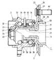
図1は、実施の形態1における車両用の従動輪側におけるハブユニットからなる内輪回転の軸受装置の断面図を示している。
【0017】
図1において、1は車輪が取り付けられるハブホイールであり、ハブホイール1の環状の軸体2の外周面には、車両インナ側から圧入して複列の転がり軸受3が外嵌装着されている。
【0018】
複列の転がり軸受3は内輪回転のアンギュラ玉軸受からなり、一対の内輪31,32、ステアリングナックルを介して車体に固定され内周面に一対の外輪軌道34,35を有した外輪33、内輪31,32の軌道ならびに外輪軌道34,35に沿って配置した複列の転動体となる玉36,37、各列の玉36,37を保持した保持器38、車両アウタ側端部を閉蓋したシール部材39にて構成されている。
【0019】
転がり軸受3は、軸体2の外周面に車両インナ側から圧入した後、軸体2にナット40を螺合して車両インナ側の内輪32の軸方向端面に締結し、さらに車両インナ側からカバー41を被せる。このようにして、玉36,37に十分な予圧を付与して、転がり軸受3を軸体2に固定する。
【0020】
次に、軸受装置の各部の構成について詳細に説明する。
【0021】
まず、軸体2は、低炭素鋼等の平板を薄肉に深絞りプレス成形してなる。図2に示すように、軸体2は、軸心方向に直線状に延びる軸部21と、軸部21の車両アウタ側端部から径方向外向きに延びるフランジ22と、軸部21の車両インナ側に段部23を介して形成され外周面にナット40を螺合するねじ溝を有した締結部24とから構成されている。
【0022】
フランジ22は、軸部21に比べ厚肉に形成されており、かつ、軸部21側の基部には略S字状に屈曲した屈曲部25が形成されている。このように、屈曲部25を形成すると共に、フランジ22を厚肉に形成したことで、フランジ22の曲げ剛性が向上する。
【0023】
また、内輪31,32は、高炭素鋼等の平板をプレス成形してなり、軸方向に対称に形成されている。
【0024】
さらに、外輪33は鍛造にて形成され、回転検出用のナックル固定タイプのアクティブセンサからなるセンサ61が貫通して設けられている。なお、回転を検出される内輪31には、パルサリング62が焼き付けによって設けられている。
【0025】
次に、軸受装置の組立てについて説明する。
【0026】
まず、軸体2の外周面に車両インナ側から転がり軸受3を圧入する。次に、ナット40を軸体2の締結部24に螺合し、内輪32に締結する。内輪31,32が、フランジ22とナット40に挟まれ、玉36,37に十分な予圧が付与されて、転がり軸受3が軸体2に固定される。
【0027】
さらに、軸体2の車両アウタ側に、ブレーキディスクやタイヤのホイール等を嵌合して位置決めするための支持部材5を設ける。支持部材5は、プレス成形品であり、軸体2の内面に圧入する圧入部51と、ホイール等を支持する支持部52とを有している。支持部材5は、軸体2の軸部21からフランジ22の屈曲部25に渡って内接した状態で、圧入部51を軸部21に圧入して固定する。そして、軸体2に固定した支持部材5の支持部52にホイール等を嵌合して位置決めし、当該支持部材5にて支持したホイール等をボルト60にてフランジ22に固定する。
【0028】
なお、軸体2と内輪31,32が、互いに軸方向や周方向にずれるのを防止するために、軸体2と内輪31,32の界面を粗面として滑り止めを施したり、内輪31,32を軸体2にスプライン嵌合したり、ローレット加工を施したりしてもよい。
【0029】
同様に、軸体2と支持部材5が、互いに軸方向や周方向にずれるのを防止するために、軸体2と支持部材5の界面を粗面として滑り止めを施したり、支持部材5を軸体2にスプライン嵌合したり、ローレット加工を施したりしてもよい。
【0030】
このように構成された軸受装置によると、軸体2が深絞りプレス成形品にて形成されており、塑性加工を中心とした加工により容易に製造でき、製造コストの低減を図ることができる。しかも、プレス成形品であるため、中空で余肉を削減でき、軽量化が図れる。
【0031】
また、軸体2のフランジ22を軸部21より厚肉としたり、軸体2のフランジ22の基部に断面略S字状に屈曲した屈曲部25を形成することで、フランジ22の曲げ剛性が向上する。
【0032】
また、軸体2がプレス成形品にて形成されているので、同容量の低炭素鋼等の平板を用いて各種形状に深絞りプレスすることができ、容易に軸体2のみを変更して、取り合いの異なる車両に対応した軸受装置を提供できる。その結果、大量生産が可能となり、製造コストの低減を図ることができる。
【0033】
また、支持部材5が、軸体2の軸部21からフランジ22の屈曲部25に渡って内接した状態で軸部21に圧入されているので、支持部材5にて軸部21を補強できる。
【0034】
さらに、軸体2ならびに支持部材5を、それぞれプレス成形にて別々に製造して圧入固定するので、従来のように鍛造にて一体成形するのに比べ、製造が容易に行え、かつ、より一層の軽量化が図れる。
【0035】
なお、支持部材5は、図1に示した構造のものに限らない。例えば、図3に示すように、ハイドロフォーム工法により、支持部52の端面を閉塞し、曲げに対する剛性を向上させたものであってもよい。
【0036】
また、転がり軸受3は、図1に示した構造のものに限らない。例えば、鍛造にて形成された内外輪の間に転動体を介装した転がり軸受等であってもよい。また、複列の転がり軸受に限らず、単列の転がり軸受でもよく、転動体も玉に限らず円すいころであってもよい。
【0037】
例えば、図4に示すように、内輪31,32が鍛造にて形成された転がり軸受3を、プレス成形品の軸体2の外周に装着したものであってもよい。なお、その他の構成は図1に示した軸受装置と同様であり、同一部分には同一符号を付してその説明を省略する。
(実施の形態2)
本発明の実施の形態2について、図5を用いて説明する。なお、図1に示した実施の形態1と同一部分は、同一符号を付してその説明を省略する。
【0038】
この実施の形態2は、支持部材5の圧入部51を車両インナ側に延ばし、当該延設部の外周面にナット40を螺合するねじ溝を形成して締結部53としたことを特徴とするものである。
【0039】
また、支持部材5に締結部53を形成したことにより、軸体2の車両インナ側には締結部を形成せず、軸部21の車両インナ側端部は内輪32の車両インナ側の端部より若干短く形成する。これにより、締結部53にナット40を螺合した際に、ナット40が内輪32の端部に締結され、玉36,37に十分な予圧が付与される。
【0040】
このように構成された軸受装置によると、実施の形態1に記載の効果に加え、支持部材5を軸体2の軸部21の内周面に沿って車両インナ側に延ばしたことにより、支持部材5にて軸体2の補強が行え、軸受強度が向上するという効果が得られる。
(実施の形態3)
本発明の実施の形態3について、図6を用いて説明する。なお、図1に示した実施の形態1と同一部分は、同一符号を付してその説明を省略する。
【0041】
この実施の形態3は、軸体2のフランジ22を厚肉とせず、フランジ22の車両アウタ側面に補助部材26を設けたことを特徴とするものである。
【0042】
すなわち、補助部材26は、低炭素鋼等の平板を薄肉に深絞りプレス成形してなる環状の部材であり、フランジ22の車両アウタ側面に接するフランジ部27と、支持部材5の外面に接するリブ28とからなる。
【0043】
そして、補助部材26を支持部材5の外面に圧入し、軸体2のフランジ22とフランジ部27とで厚肉のフランジを構成し、ホイール等をボルト60にて固定する。
【0044】
このように構成された軸受装置においても、実施の形態1に記載の効果と同様の効果が得られる。
(実施の形態4)
本発明の実施の形態4について、図7を用いて説明する。なお、図1に示した実施の形態1と同一部分は、同一符号を付してその説明を省略する。
【0045】
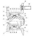
この実施の形態4は、ハブユニットからなる外輪回転の軸受装置であって、軸体2の車両インナ側に、ステアリングナックルを介して車体に固定するフランジ22を有したことを特徴とするものである。
【0046】
軸体2は、低炭素鋼等の平板を薄肉に深絞りプレス成形してなり、軸心方向に直線状に延びる軸部21と、軸部21の車両インナ側端部から径方向外向きに延びる厚肉のフランジ22と、軸部21の車両アウタ側に段部23を介して形成され外周面にナット40を螺合するねじ溝を有した締結部24とから構成されている。
【0047】
また、転がり軸受3は、鍛造製の内外輪31,32,33と、内輪31,32と外輪33の軌道34,35との間に介装され保持器38にて保持された玉36,37と、両端を閉蓋したシール部材39にて構成されている。
【0048】
さらに、軸体2の軸部21ならびに内輪31,32を貫通して回転検出用のセンサ61が設けられており、かつ、回転を検出される外輪33には、パルサリング62が設けられている。なお、センサ61は、ナックル固定タイプのアクティブセンサであり、軸体2に圧入したプレス品の取付板70に取付けられている。また、パルサリング62は、外輪33の内周面に圧入してかしめ固定されている。また、フランジ22の車両インナ側面には、ナックルを嵌合して位置決めする爪71が数箇所に塑性加工にて形成されている。
【0049】
このように構成された軸受装置によると、実施の形態1に記載の効果に加え、センサ61が軸体2の内部に収納されているため、センサ61が軸体2にて保護され、、センサ61の破損や断線等を防止できる。さらに、センサ61を固定する取付板70は軽量のプレス品であり、かつ、取付板70にて軸体2の開口端を閉蓋でき、軸体2内に異物等が侵入するのを防止でき、センサ61の寿命が向上するという効果が得られる。
【0050】
図8に、実施の形態4の軸受装置の変形例を示す。
【0051】
この軸受装置は、センサ61を取り付けるプレス品の取付板72に、ナックルを嵌合して位置決めする爪73を一体に形成したものであり、その他の構成は図7の例と同様であり、同一部分には同一符号を付してその説明を省略する。
【0052】
なお、本発明は、上述の各実施の形態に示すように、ハブユニットからなる車軸用の軸受装置に限るものではなく、各種軸受装置に適用してもよい。
【0053】
【発明の効果】
本発明の軸受装置によれば、製造性に優れ、軽量で安価であるという効果が得られる。
【図面の簡単な説明】
【図1】本発明の実施の形態1における軸受装置の断面図である。
【図2】本発明の実施の形態1における軸受装置の軸体の断面図である。
【図3】本発明の実施の形態1における軸受装置の支持部材の変形例の断面図である。
【図4】本発明の実施の形態1における軸受装置の変形例の断面図である。
【図5】本発明の実施の形態2における軸受装置の断面図である。
【図6】本発明の実施の形態3における軸受装置の断面図である。
【図7】本発明の実施の形態4における軸受装置の断面図である。
【図8】本発明の実施の形態4における軸受装置の変形例の断面図である。
【符号の説明】
1 ハブホイール
2 軸体
21 軸部
22 フランジ
24,53 締結部
25 屈曲部
3 転がり軸受
31,32 内輪
33 外輪
34,35 外輪軌道
36,37 玉(転動体)
40 ナット
5 支持部材[0001]
BACKGROUND OF THE INVENTION
The present invention relates to a bearing device in which a rolling bearing is mounted on the outer periphery of a shaft body such as a vehicle hub unit.
[0002]
[Prior art]
A hub unit for a vehicle generally has a structure in which a double-row rolling bearing is mounted on the outer periphery of a shaft body of a hub wheel so as to prevent the hub wheel from coming off.
[0003]
For example, in the case of inner ring rotation, the rolling bearing includes an inner ring mounted on the outer periphery of the shaft body, an outer ring fixed to the vehicle body via a steering knuckle, a double row rolling element disposed between the inner ring and the outer ring, and holding the rolling element. And a sealing member with a closed end.
[0004]
[Problems to be solved by the invention]
Conventionally, a shaft body to which a rolling bearing is attached is formed by forging using a high-strength material that can withstand the load of the bearing.
[0005]
However, in the case of forging, there is a possibility that processing takes time and costs are increased, and the weight is also increased.
[0006]
An object of the present invention is to provide a lightweight and inexpensive bearing device that is excellent in manufacturability.
[0007]
[Means for Solving the Problems]
A bearing device according to the present invention includes ashaft body, an inner ring mounted on the outer peripheral surface of the shaft body, an outer ring disposed concentrically on the outer periphery of the inner ring, and interposed between the inner ring and the outer ring. A rolling element, and the shaft body is formed of a deep drawing press-molded product, and includes a shaft portion extending linearly in the axial direction and a flange extending radially outward from an end portion of the shaft portion. And, on the flange side of the shaft body, a support member formed of a deep-drawing press-molded product that supports a brake disk, a wheel, etc. is press-fitted inwardly across the flange from the shaft portion,wherein the outer peripheral surface in the counter-flange side of the support member to form a fastening section having a thread groove, by fastening the nuts to the fastening part in the axial end face of the screwed inner ring, and applying a preload to the rolling elements The inner ring is fixed to a shaft body.
[0008]
Note that the shaft body flange may be thicker than the shaft portion, or a bent portion that is bent in a substantially S-shaped cross section may be formed at the base portion of the shaft body flange.
[0009]
In addition, a fastening portion having a thread groove on the outer peripheral surface is formed on the opposite side of the shaft body, and a nut is screwed onto the fastening portion and fastened to the end surface in the axial direction of the inner ring. The inner ring may be fixed to the shaft body.
[0010]
According to the bearing device of the present invention, the shaft body is formed of a deep drawing press-molded product, which can be easily manufactured by processing centering on plastic processing, and the manufacturing cost can be reduced. In addition, since it is a press-molded product, it is hollow and can reduce the surplus thickness and can be reduced in weight.
[0011]
Moreover, the bending rigidity of a flange improves by making the flange of a shaft body thicker than a shaft part, or forming the bending part bent in the substantially S-shaped cross section in the base part of the flange of a shaft body.
[0015]
DETAILED DESCRIPTION OF THE INVENTION
(Embodiment 1)
[0016]
FIG. 1 shows a cross-sectional view of a bearing device for rotating an inner ring comprising a hub unit on the side of a vehicle driven wheel in the first embodiment.
[0017]
In FIG. 1,
[0018]
The double-
[0019]
The rolling
[0020]
Next, the configuration of each part of the bearing device will be described in detail.
[0021]
First, the
[0022]
The
[0023]
The
[0024]
Further, the
[0025]
Next, assembly of the bearing device will be described.
[0026]
First, the rolling
[0027]
Further, a
[0028]
In order to prevent the
[0029]
Similarly, in order to prevent the
[0030]
According to the bearing device configured as described above, the
[0031]
Further, the
[0032]
Moreover, since the
[0033]
Further, since the
[0034]
Further, since the
[0035]
The
[0036]
Further, the rolling
[0037]
For example, as shown in FIG. 4, a rolling
(Embodiment 2)
A second embodiment of the present invention will be described with reference to FIG. In addition, the same part as
[0038]
The second embodiment is characterized in that the press-
[0039]
Further, since the
[0040]
According to the bearing device configured as described above, in addition to the effects described in the first embodiment, the
(Embodiment 3)
A third embodiment of the present invention will be described with reference to FIG. In addition, the same part as
[0041]
The third embodiment is characterized in that the
[0042]
That is, the
[0043]
Then, the
[0044]
Also in the bearing device configured as described above, the same effects as those described in the first embodiment can be obtained.
(Embodiment 4)
Embodiment 4 of the present invention will be described with reference to FIG. In addition, the same part as
[0045]
The fourth embodiment is a bearing device for rotating an outer ring comprising a hub unit, and is characterized by having a
[0046]
The
[0047]
Further, the rolling
[0048]
Further, a
[0049]
According to the bearing device configured as described above, in addition to the effects described in the first embodiment, since the
[0050]
FIG. 8 shows a modification of the bearing device according to the fourth embodiment.
[0051]
In this bearing device, a
[0052]
Note that the present invention is not limited to the axle bearing device including the hub unit as shown in the above-described embodiments, and may be applied to various bearing devices.
[0053]
【The invention's effect】
According to the bearing device of the present invention, it is possible to obtain the effects of excellent manufacturability, light weight and low cost.
[Brief description of the drawings]
FIG. 1 is a cross-sectional view of a bearing device according to a first embodiment of the present invention.
FIG. 2 is a sectional view of a shaft body of the bearing device according to the first embodiment of the present invention.
FIG. 3 is a cross-sectional view of a modified example of the support member of the bearing device according to the first embodiment of the present invention.
FIG. 4 is a cross-sectional view of a modified example of the bearing device according to the first embodiment of the present invention.
FIG. 5 is a sectional view of a bearing device according to a second embodiment of the present invention.
FIG. 6 is a sectional view of a bearing device according to a third embodiment of the present invention.
FIG. 7 is a sectional view of a bearing device according to a fourth embodiment of the present invention.
FIG. 8 is a cross-sectional view of a modified example of the bearing device according to the fourth embodiment of the present invention.
[Explanation of symbols]
DESCRIPTION OF
40
Claims (1)
Translated fromJapanese前記支持部材の反フランジ側に外周面にねじ溝を有した締結部を形成し、前記締結部にナットを螺合し内輪の軸方向端面に締結することにより、転動体に予圧を付与して前記内輪を軸体に固定したことを特徴とする軸受装置。A shaft body, an inner ring attached to the outer peripheral surface of the shaft body, an outer ring disposed concentrically on the outer periphery of the inner ring, and a rolling element interposed between the inner ring and the outer ring, The shaft body is formed of a deep drawing press-molded product, and includes a shaft portion extending linearly in the axial direction and a flange extending radially outward from the end portion of the shaft portion, and the flange of the shaft body On the side, a support member formed of a deep-drawing press-molded product that supports a brake disk, a wheel, etc. is press-fitted while being inscribed across the flange from the shaft portion,
Wherein the outer peripheral surface in the counter-flange side of the support member to form a fastening section having a thread groove, by fastening the nuts to the fastening part in the axial end face of the screwed inner ring, and applying a preload to the rolling elementsBearing device characterized in that fixed to the inner ring to the shaft member.
Priority Applications (1)
| Application Number | Priority Date | Filing Date | Title |
|---|---|---|---|
| JP2001359383AJP4003446B2 (en) | 2001-11-26 | 2001-11-26 | Bearing device |
Applications Claiming Priority (1)
| Application Number | Priority Date | Filing Date | Title |
|---|---|---|---|
| JP2001359383AJP4003446B2 (en) | 2001-11-26 | 2001-11-26 | Bearing device |
Related Child Applications (1)
| Application Number | Title | Priority Date | Filing Date |
|---|---|---|---|
| JP2007177969ADivisionJP2007278518A (en) | 2007-07-06 | 2007-07-06 | Vehicle bearing device |
Publications (2)
| Publication Number | Publication Date |
|---|---|
| JP2003159904A JP2003159904A (en) | 2003-06-03 |
| JP4003446B2true JP4003446B2 (en) | 2007-11-07 |
Family
ID=19170404
Family Applications (1)
| Application Number | Title | Priority Date | Filing Date |
|---|---|---|---|
| JP2001359383AExpired - Fee RelatedJP4003446B2 (en) | 2001-11-26 | 2001-11-26 | Bearing device |
Country Status (1)
| Country | Link |
|---|---|
| JP (1) | JP4003446B2 (en) |
Cited By (1)
| Publication number | Priority date | Publication date | Assignee | Title |
|---|---|---|---|---|
| WO2012011297A1 (en)* | 2010-07-22 | 2012-01-26 | 日本精工株式会社 | Rolling bearing unit with encoder for supporting drive wheel |
Families Citing this family (8)
| Publication number | Priority date | Publication date | Assignee | Title |
|---|---|---|---|---|
| ATE492423T1 (en) | 2004-01-29 | 2011-01-15 | Yanmar Co Ltd | TRACTOR |
| JP4352927B2 (en) | 2004-02-20 | 2009-10-28 | 日本精工株式会社 | Method for manufacturing race ring member constituting hub unit for supporting wheel |
| JP4986116B2 (en)* | 2006-06-13 | 2012-07-25 | Ntn株式会社 | Wheel bearing device |
| JP5052847B2 (en)* | 2006-09-07 | 2012-10-17 | Ntn株式会社 | Wheel bearing device |
| DE112007002599T5 (en) | 2006-11-07 | 2010-01-14 | Ntn Corp. | Wheel bearing device for a vehicle |
| JP4205752B2 (en)* | 2006-11-07 | 2009-01-07 | Ntn株式会社 | Wheel bearing device |
| JP5641705B2 (en)* | 2009-04-02 | 2014-12-17 | Ntn株式会社 | Wheel bearing device |
| JP5417239B2 (en)* | 2010-03-30 | 2014-02-12 | Ntn株式会社 | Wheel bearing device and manufacturing method thereof |
- 2001
- 2001-11-26JPJP2001359383Apatent/JP4003446B2/ennot_activeExpired - Fee Related
Cited By (5)
| Publication number | Priority date | Publication date | Assignee | Title |
|---|---|---|---|---|
| WO2012011297A1 (en)* | 2010-07-22 | 2012-01-26 | 日本精工株式会社 | Rolling bearing unit with encoder for supporting drive wheel |
| CN102481806A (en)* | 2010-07-22 | 2012-05-30 | 日本精工株式会社 | Rolling bearing unit for wheel support with coding device |
| US8882358B2 (en) | 2010-07-22 | 2014-11-11 | Nsk Ltd. | Rolling bearing unit with encoder for supporting wheel |
| US9091303B2 (en) | 2010-07-22 | 2015-07-28 | Nsk Ltd. | Rolling bearing unit with encoder for supporting wheel |
| CN102481806B (en)* | 2010-07-22 | 2016-03-02 | 日本精工株式会社 | Rolling bearing unit for wheel support with coding device |
Also Published As
| Publication number | Publication date |
|---|---|
| JP2003159904A (en) | 2003-06-03 |
Similar Documents
| Publication | Publication Date | Title |
|---|---|---|
| JP4911333B2 (en) | Wheel mounting structure in a wheel bearing device | |
| JP4345988B2 (en) | Wheel bearing device | |
| JP4003446B2 (en) | Bearing device | |
| JP2007100826A (en) | Wheel bearing device | |
| JP2007278518A (en) | Vehicle bearing device | |
| JP2003074570A (en) | Bearing device for wheel | |
| JP4085736B2 (en) | Rolling bearing device | |
| JP4151262B2 (en) | Hub unit for vehicles | |
| JP4078945B2 (en) | Rolling bearing device | |
| JP6309228B2 (en) | Manufacturing method of wheel bearing device | |
| JP2000310228A (en) | Rolling bearing unit for wheel support | |
| JP4013618B2 (en) | Rolling bearing device | |
| JP2000168306A (en) | Bearing device for wheel | |
| US20080304784A1 (en) | Rolling Bearing Assembly | |
| JP4239542B2 (en) | Rolling bearing device | |
| US20130301968A1 (en) | Hub spindle bearing unit for wheel | |
| JP4260055B2 (en) | Wheel bearing device | |
| JP2004150485A (en) | Rolling bearing device | |
| JP4658028B2 (en) | Manufacturing method of wheel bearing device | |
| JPH10181304A (en) | Hub unit bearings for wheels | |
| JP2024123777A (en) | Wheel bearing device | |
| JP7619117B2 (en) | Wheel drive unit and assembly method thereof | |
| US12064993B2 (en) | Bearing device for vehicle wheel | |
| JP2004176747A (en) | Double row tapered roller bearing unit for supporting wheel | |
| JP4492436B2 (en) | Magnetic encoder and rolling bearing device using the same |
Legal Events
| Date | Code | Title | Description |
|---|---|---|---|
| A621 | Written request for application examination | Free format text:JAPANESE INTERMEDIATE CODE: A621 Effective date:20040908 | |
| A977 | Report on retrieval | Free format text:JAPANESE INTERMEDIATE CODE: A971007 Effective date:20070126 | |
| A131 | Notification of reasons for refusal | Free format text:JAPANESE INTERMEDIATE CODE: A131 Effective date:20070508 | |
| A521 | Written amendment | Free format text:JAPANESE INTERMEDIATE CODE: A523 Effective date:20070705 | |
| TRDD | Decision of grant or rejection written | ||
| A01 | Written decision to grant a patent or to grant a registration (utility model) | Free format text:JAPANESE INTERMEDIATE CODE: A01 Effective date:20070731 | |
| A61 | First payment of annual fees (during grant procedure) | Free format text:JAPANESE INTERMEDIATE CODE: A61 Effective date:20070813 | |
| R150 | Certificate of patent or registration of utility model | Free format text:JAPANESE INTERMEDIATE CODE: R150 | |
| FPAY | Renewal fee payment (event date is renewal date of database) | Free format text:PAYMENT UNTIL: 20100831 Year of fee payment:3 | |
| FPAY | Renewal fee payment (event date is renewal date of database) | Free format text:PAYMENT UNTIL: 20110831 Year of fee payment:4 | |
| FPAY | Renewal fee payment (event date is renewal date of database) | Free format text:PAYMENT UNTIL: 20120831 Year of fee payment:5 | |
| FPAY | Renewal fee payment (event date is renewal date of database) | Free format text:PAYMENT UNTIL: 20130831 Year of fee payment:6 | |
| LAPS | Cancellation because of no payment of annual fees |