JP4003365B2 - Vending machine beverage cooking equipment - Google Patents
Vending machine beverage cooking equipmentDownload PDFInfo
- Publication number
- JP4003365B2 JP4003365B2JP37269999AJP37269999AJP4003365B2JP 4003365 B2JP4003365 B2JP 4003365B2JP 37269999 AJP37269999 AJP 37269999AJP 37269999 AJP37269999 AJP 37269999AJP 4003365 B2JP4003365 B2JP 4003365B2
- Authority
- JP
- Japan
- Prior art keywords
- hot water
- raw material
- beverage
- water supply
- stirring
- Prior art date
- Legal status (The legal status is an assumption and is not a legal conclusion. Google has not performed a legal analysis and makes no representation as to the accuracy of the status listed.)
- Expired - Fee Related
Links
- 235000013361beverageNutrition0.000titleclaimsdescription30
- 238000010411cookingMethods0.000titleclaimsdescription29
- XLYOFNOQVPJJNP-UHFFFAOYSA-NwaterSubstancesOXLYOFNOQVPJJNP-UHFFFAOYSA-N0.000claimsdescription120
- 239000002994raw materialSubstances0.000claimsdescription43
- 238000003756stirringMethods0.000claimsdescription36
- 239000000843powderSubstances0.000description14
- 239000011347resinSubstances0.000description14
- 229920005989resinPolymers0.000description14
- 230000002093peripheral effectEffects0.000description12
- 239000007788liquidSubstances0.000description7
- 238000013019agitationMethods0.000description4
- 239000000463materialSubstances0.000description4
- 238000004519manufacturing processMethods0.000description3
- 238000010586diagramMethods0.000description2
- 230000000694effectsEffects0.000description2
- 238000004140cleaningMethods0.000description1
- 235000013353coffee beverageNutrition0.000description1
- 235000012171hot beverageNutrition0.000description1
- 239000011259mixed solutionSubstances0.000description1
Images


Landscapes
- Beverage Vending Machines With Cups, And Gas Or Electricity Vending Machines (AREA)
- Apparatus For Making Beverages (AREA)
Description
Translated fromJapanese【0001】
【発明の属する技術分野】
本発明はカップ式自動販売機に関し、特に、粉末原料と湯とを攪拌・混合してコーヒー飲料等を作る自動販売機の飲料調理装置に関する。
【0002】
【従来の技術】
従来、飲料調理装置としては、特開平8−101967号公報に記載されているようなものが知られている。飲料調理装置は、蓋体と、蓋体に嵌合するようにして着脱自在に取り付けられたボール本体と、ボール本体内で粉末原料と湯とを攪拌・混合する攪拌機構とで構成されている。また、蓋体は蓋本体と、蓋本体の上側に設けたベース体とで構成されている。
【0003】
従来例における飲料調理装置の一例としての蓋本体とボール本体を示した図5に基づいて説明すると、蓋本体4には、ボール本体2内に粉末原料を導入する原料導入口25と、湯を導入する湯供給管8と、湯気を排気する湯気排気管7が形成されている。また、蓋本体4の外周面には湯供給管8に連なる湯流下溝26が形成されており、この湯流下溝26外周とボール本体2の上端部内周面とが嵌合して、この間に環状の湯通路が構成される。湯流下溝26には周方向に多数の小孔27が形成され、この小孔27から湯がボール本体2の内周面を伝わって流下するようになっている。
【0004】
飲料の調理を行う場合には、ボール本体2に、湯供給管8から湯を注ぎ込むと共に、原料導入口25から粉末原料を導入する。湯は環状に形成された湯通路からボール本体2の内面を洗うように供給される。これら導入した湯と粉末原料を、ボール本体2内に設けた、図示していない鉛直軸に攪拌羽根を取り付けた攪拌機構で攪拌する。一方、リンスを行う場合には、原料導入口25や湯気抜き口20に達する水位まで湯供給管8から湯を注ぎ込む。湯は環状に形成された湯通路からボール本体2の内面を洗うように供給される。これを上記の攪拌機構で攪拌し、ボール本体2と原料導入口25や湯気抜き口20を洗浄する。
【0005】
【発明が解決しようとする課題】
しかしながら、従来の飲料調理装置では、蓋本体4の外周面に形成した湯流下溝26とボール本体2の上端部内周面との間に環状の湯通路を設け、飲料の調理やリンス(洗浄)を行う時、この環状に形成された湯流下溝26に設けた多数の小孔27からボール本体2の内面を洗うように湯を供給しているため、長期間使用すると原料や湯スケール(例えば水道水中の不純物が堆積したもの)が湯流下溝26の小孔27に詰まることがあり、長期的に安定した飲料調理を行うには、定期的に蓋本体4を取り外して、手作業により湯流下溝26の小孔27に詰まった原料や湯スケールを除去しなければならないため、作業が煩雑となる問題があった。また、蓋本体4に環状の湯流下溝26を設ける必要があるため、蓋本体4の構造が複雑となり、飲料調理装置が大型化し、コストアップとなる問題があった。また、湯流下溝26外周とボール本体2の上端部内周面を嵌合させ環状の湯通路を構成する必要から、嵌合部分から湯が漏れないように、嵌合部分には特に正確な寸法が要求されるため、生産の歩留まりが悪くなる問題がある。さらに、湯と湯通路の接触面が広く、且つ湯流下溝26の小孔27から湯を流下するために湯の湯通路滞留時間が長くなるため、湯温度が下がりやすく、温かい飲料を提供するには不都合があった。
【0006】
そこで、原料や湯スケールの詰まりを除去でき、また、特に正確な寸法が要求される嵌合部分をなくした、小型で安価、しかも、湯滞留時間を短くできる、自動販売機の飲料調理装置を提供することを目的とする。
【0007】
【課題を解決するための手段】
上記課題を解決するため、請求項1にかかる発明は、攪拌容器内に原料と湯とを導入し、これを攪拌して飲料を作る自動販売機の飲料調理装置において、湯を攪拌容器内に導入するための湯供給口と、攪拌容器の上端部内壁面の周方向に沿って設けられ、湯供給口と対向する一部を幅広とした段差部と、を備え、湯供給口から導入された湯は、幅広とした段差部に衝突した後、段差部の上面を伝わりながら攪拌容器内部を流下することを特徴とするものである。
【0009】
【発明の実施の形態】
以下、本発明の実施の形態を図を参照して説明する。
【0010】
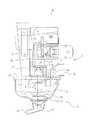
図1は、本発明の実施の形態に係る飲料調理装置1の一例として示した断面図であって、ボール本体(攪拌容器)2と、ボール本体2が取り付けられる蓋体3とで構成され、蓋体3の部分で自動販売機内に支持されている。また、蓋体3は蓋本体4と、蓋本体4の上側に設けたベース体5とで構成されている。
【0011】
蓋本体4には、縁部に、図外のファンに連なる排気管7と、図外の湯タンクに連なる湯供給管8とが、ベース体5には、中央部に、攪拌モータ6が取り付けられると共に、飲料調理装置1内に粉末原料を供給する原料シュート9が取り付けられている。
【0012】
販売指令により、ボール本体2には、原料シュート9を介して図外の原料容器から所定量の粉末原料が供給され、同時に、湯供給管8を介して湯タンクから所定量の湯が供給されて、粉末原料と湯の攪拌が行われる。また、その際に発生するボール本体2内の湯気は、ファンにより排気管7を介してボール本体2の外部に排気される。このようにして所定時間、粉末原料と湯の攪拌が行われると、攪拌が停止し、ボール本体2の吐出口10から図外のフィルタを介して、粉末原料と湯の混合液がカップに供給される。一方、ボール本体2をリンスする場合には、蓋本体4の下面が浸かる位置まで湯が満たされ、湯の攪拌が行われる。
【0013】
ボール本体2は、透明な樹脂容器11内に攪拌機構12を収容したものであり、樹脂容器11は、攪拌が効率良く行われるように、小判型の広口開口上端部から徐々に絞り込んだ下端部に至る変形ロート状に形成されている。樹脂容器11の上端部は広く開放され、蓋体3に嵌合するようにして着脱自在に取り付けられている。ボール本体2の下部は吐出口10を有する別部材で構成されており、これにより後述する鉛直軸13の軸端が覆われると共に、粉末原料と湯の混合液がフィルター側に導かれる。
【0014】
攪拌機構12は、上端部を継手14を介して攪拌モータ6に連結された鉛直軸13と、鉛直軸13にそれぞれ取り付けられたリンス用攪拌羽根15、調理用攪拌羽根16および弁羽根17とで構成されている。調理用攪拌羽根16は混合液に埋没する位置に配設され、弁羽根17は鉛直軸13の最下部に配設されている。調理用攪拌羽根16および弁羽根17は、回転に伴って混合液の流下を阻止する弁の機能を有すると共に、粉末原料と湯とを混合する(調理)機能を有している。また、リンス用攪拌羽根15は、混合液の液位より高い位置に配設されていて、常時は空回転するが、樹脂容器11にリンス用の湯を満たした場合には、リンス用の湯に埋没し、回転に伴って、樹脂容器11の内面を洗浄する。
【0015】
蓋本体4には、原料シュート9が臨む原料導入空間18と、湯供給管8に連なる湯供給口19と、排気管7に連なる湯気抜き口20とが形成されている。また、樹脂容器11の上端部内壁面には周方向に沿って湯供給口19と対向する段差21(段差部)を形成し、さらに湯供給口19の下方に、湯供給口19から勢いよく供給された湯が当たり、湯が飛散し、且つ、湯が段差21の周方向に流れるに足る幅の幅広段差21aを段差21の一部に設けることにより、図3に示すように湯供給管8に連なる湯供給口19から勢いよく供給された湯が幅広段差21aに当たり、飛散すると共に、段差21の周方向に流れ、樹脂容器11の内周面を伝わって流下するようになっている。
【0016】
一方、ベース体5には、原料シュート9の下端部に臨むように第2の湯気抜き口22が形成され、この第2の湯気抜き口22は、攪拌モータ6の継手14を迂回するように設けた副排気通路23を介して、排気管7に連通されている。第2の湯気抜き口22は、原料シュート9に近接して開口しており、上動した原料シュート9の下側空間の空気(湯気)を吸引(排気)する。この場合、原料シュート9の背板9aが、第2の湯気抜き口22を開閉させるゲートを兼ねており、原料シュート9が下動すると、第2の湯気抜き口22は閉塞され、上動すると開放されるようになっている。リンス時には、湯の水位が湯気抜き口20や原料導入空間18にまで達するため、排気管7で構成される主排気通路24では、原料導入空間18側の湯気抜きが不可能になる。このため、第2の湯気抜き口22に連なるこの副排気通路23により、原料導入空間18側の湯気抜きが行えるようになっている。
【0017】
次に、図1を参照して販売動作(調理動作)を説明する。
【0018】
図1に示すように、販売指令により、先ず攪拌モータ6が駆動を開始し、同時にボール本体2内に、湯と粉末原料が導入され、さらにこれらに相前後して湯気の排気動作が開始される。湯は、樹脂容器11の上端部内壁面に形成されている幅広段差21aを介して、内壁面の周方向に沿って形成されている段差21から湯が樹脂容器11の内周面を伝わって流下することによりボール本体2の内面を洗うように供給される。一方、粉末原料は、下動位置にある原料シュート9から原料導入空間18を介して落とし込まれる。さらに、湯気の排気は、原料導入空間18から外気を吸い込んで、これを湯気抜き口20から排気するようにして行われる。そして、所定量の湯と粉末原料が供給され、これらの混合液の攪拌が所定時間行われると、攪拌モータ6が停止し、混合液は吐出口10から自動的に流下する。このようにして、販売動作が繰り返されるが、販売動作が所定の回数行われ、あるいはオペレータのスイッチ操作で、定期的にボール本体2内のリンスが行われる。
【0019】
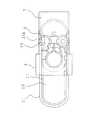
次に、図4を参照してリンス動作を説明する。
【0020】
図4に示すように、飲料調理装置1がリンスモードに移行すると、攪拌モータ6が駆動を開始し、同時にボール本体2内に湯が供給され、かつ湯気の排気動作が開始される。また、湯の供給に先立ち、原料シュート9が上動位置に移動される。この場合、湯は、原料導入空間18や湯気抜き口20に達する水位まで、ボール本体2内に満たされ、湯の浅い部分はリンス用攪拌羽根15により、深い部分は調理用攪拌羽根16および弁羽根17により、リンス用の攪拌が行われる。一方、湯気は、湯気抜き口20が湯で満たされる(閉塞される)とともに、原料シュート9の上動に伴い第2の湯気抜き口22が開放されるため、原料シュート9の下側空間、すなわち、原料導入空間18内の湯気が、原料シュート9に向かって立ちのぼらないように、第2の湯気抜き口22から排気される。
【0021】
これによって、ボール本体2に湯を供給するにあたり、蓋本体4の外周面に湯流下溝26を形成し、樹脂容器11の上端部内周面との間に環状の湯通路を設ける代わりに、樹脂容器11の上端部内壁面に周方向に沿って湯供給口19と対向する段差21を形成し、さらに湯供給口19下部に臨む段差21の一部を幅広段差21aとすることにより、湯供給口19から勢いよく供給された湯が幅広段差21aに当たり、飛散すると共に、段差21の周方向に流れ、樹脂容器11の内周面を伝わって流下するようにしているので、原料や湯スケールが湯流下溝26の小孔27に詰まることがなくなり、長期的に飲料調理を行っても、定期的に蓋本体4を取り外して、原料や湯スケールを除去する煩雑な作業を防止できる。また、蓋本体4の外周面に湯流下溝26を形成し、環状の湯通路を設ける必要がなくなることから、嵌合部分から湯が漏れないように、嵌合部分に特に正確な寸法を要求することがなく、生産の歩留まりが良くなり、装置が小型化し、コストダウンを図ることができる。さらに、湯と湯通路の接触面が少なくなり、湯の滞留時間が短くなるので湯温低下が少なく、従来に比べて、より温かく美味しい飲料を提供することができるという利点がある。
【0022】
【発明の効果】
以上説明したように本発明によれば、攪拌容器内に原料と湯とを導入し、これを攪拌して飲料を作る自動販売機の飲料調理装置において、湯を攪拌容器内に導入するための湯供給口と、攪拌容器の上端部内壁面の周方向に沿って設けられ、一部が湯供給口と対向する段差部と、を備え、湯供給口から導入された湯は、段差部に衝突した後、段差部の上面を伝わりながら攪拌容器内部を流下することにより、蓋本体の外周面に湯流下溝を形成し、環状の湯通路を設ける必要がなくなることから、攪拌容器の内面を洗うように湯を供給しても、原料や湯スケールを除去する煩雑な作業がなくなり、生産の歩留まりが向上し、装置を小型化することにより、コストダウンを図ることができるとともに、湯温低下が少なくなる結果、従来に比べて、より温かく美味しい飲料を提供することができるようになる。
【0023】
また、湯供給口と対向する段差部の一部を、幅広とすることにより、攪拌容器の内面を洗うように湯を供給するとき、攪拌容器の内面を洗浄する効果がさらに大となる。
【図面の簡単な説明】
【図1】本発明の実施の形態に係る飲料調理装置の一例として示した調理動作を表した断面図である。
【図2】本発明の実施の形態に係る飲料調理装置の一例として示した平面図である。
【図3】本発明の実施の形態に係る飲料調理装置の一例として、飲料の調理やリンスを行う時、樹脂容器の幅広段差を介して段差から湯が流れる状態を表す図である。
【図4】本発明の実施の形態に係る飲料調理装置の一例として示したリンス動作を表した断面図である。
【図5】従来例における飲料調理装置の一例として、飲料の調理やリンスを行う時、環状に形成された湯流下溝に設けた多数の小孔から湯が流れる状態を表す図である。
【符号の説明】
1 飲料調理装置
2 ボール本体
3 蓋体
4 蓋本体
7 湯気排気管
8 湯供給管
10 吐出口
11 樹脂容器
12 攪拌機構
19 湯供給口
21 段差
21a 幅広段差
26 湯流下溝
27 小孔[0001]
BACKGROUND OF THE INVENTION
The present invention relates to a cup-type vending machine, and more particularly, to a beverage cooking device for a vending machine that stirs and mixes a powder raw material and hot water to make a coffee beverage or the like.
[0002]
[Prior art]
Conventionally, as a beverage cooking apparatus, what is described in Unexamined-Japanese-Patent No. 8-101967 is known. The beverage cooking apparatus includes a lid, a ball body that is detachably attached so as to be fitted to the lid, and a stirring mechanism that stirs and mixes the powder raw material and hot water in the ball body. . Further, the lid body is composed of a lid body and a base body provided on the upper side of the lid body.
[0003]
Referring to FIG. 5 showing a lid body and a ball body as an example of a beverage cooking apparatus in the conventional example, the
[0004]
When cooking a beverage, hot water is poured into the
[0005]
[Problems to be solved by the invention]
However, in the conventional beverage cooking apparatus, an annular hot water passage is provided between the hot water
[0006]
Therefore, a vending machine beverage cooking device that can eliminate clogging of raw materials and hot water scale, eliminates a fitting part that requires particularly accurate dimensions, and can reduce hot water residence time. The purpose is to provide.
[0007]
[Means for Solving the Problems]
In order to solve the above-mentioned problems, the invention according to claim 1 is directed to a beverage cooking apparatus of a vending machine that introduces raw materials and hot water into a stirring container and stirs them to make a beverage. A hot water supply port for introductionand a stepped portion provided along the circumferential direction of the inner wall surface of the upper end portion of the stirring vesseland having a part widened facing the hot water supply port were introduced from the hot water supply port. The hot water is characterized in that after colliding with awide stepped portion , the hot water flows down the stirring vessel while traveling along the upper surface of the stepped portion.
[0009]
DETAILED DESCRIPTION OF THE INVENTION
Hereinafter, embodiments of the present invention will be described with reference to the drawings.
[0010]
FIG. 1 is a cross-sectional view illustrating an example of a beverage cooking apparatus 1 according to an embodiment of the present invention, which includes a ball body (stirring container) 2 and a lid 3 to which the
[0011]
The
[0012]
According to the sales command, a predetermined amount of powdered raw material is supplied to the
[0013]
The
[0014]
The
[0015]
The
[0016]
On the other hand, a
[0017]
Next, the selling operation (cooking operation) will be described with reference to FIG.
[0018]
As shown in FIG. 1, according to the sales command, the agitation motor 6 starts to be driven first, and at the same time, hot water and powder raw material are introduced into the
[0019]
Next, the rinsing operation will be described with reference to FIG.
[0020]
As shown in FIG. 4, when the beverage cooking apparatus 1 shifts to the rinse mode, the agitation motor 6 starts to drive, and at the same time, hot water is supplied into the
[0021]
Thus, when supplying hot water to the
[0022]
【The invention's effect】
As described above, according to the present invention, in the beverage cooking apparatus of a vending machine that introduces raw materials and hot water into a stirring vessel and stirs them to make a beverage, the hot water is introduced into the stirring vessel. A hot water supply port and a stepped portion that is provided along the circumferential direction of the inner wall surface of the upper end portion of the stirring vessel, and a part of the step is opposed to the hot water supply port, and the hot water introduced from the hot water supply port collides with the stepped portion. After that, the inside of the stirring vessel is made to flow down along the upper surface of the stepped portion, so that a hot water flow down groove is formed on the outer peripheral surface of the lid body, and there is no need to provide an annular hot water passage. Thus, even if hot water is supplied, the complicated work of removing raw materials and hot water scale is eliminated, the production yield is improved, the size of the apparatus is reduced, the cost can be reduced, and the hot water temperature is reduced. As a result, it is better So it is possible to provide a warm and delicious drink.
[0023]
Moreover, when the hot water is supplied so as to wash the inner surface of the stirring container, the effect of cleaning the inner surface of the stirring container is further increased by widening a part of the step portion facing the hot water supply port.
[Brief description of the drawings]
FIG. 1 is a cross-sectional view showing a cooking operation shown as an example of a beverage cooking apparatus according to an embodiment of the present invention.
FIG. 2 is a plan view showing an example of a beverage cooking apparatus according to an embodiment of the present invention.
FIG. 3 is a diagram illustrating a state in which hot water flows from a step through a wide step of a resin container when a beverage is cooked or rinsed as an example of a beverage cooking apparatus according to an embodiment of the present invention.
FIG. 4 is a sectional view showing a rinsing operation as an example of a beverage cooking apparatus according to an embodiment of the present invention.
FIG. 5 is a diagram illustrating a state in which hot water flows from a plurality of small holes provided in a ring-shaped hot water lower groove when a beverage is cooked or rinsed as an example of a beverage cooking apparatus in a conventional example.
[Explanation of symbols]
DESCRIPTION OF SYMBOLS 1
Claims (1)
Translated fromJapanese湯を前記攪拌容器内に導入するための湯供給口と、
前記攪拌容器の上端部内壁面の周方向に沿って設けられ、前記湯供給口と対向する一部を幅広とした段差部と、を備え、
前記湯供給口から導入された湯は、前記幅広とした段差部に衝突した後、前記段差部の上面を伝わりながら前記攪拌容器内部を流下することを特徴とする自動販売機の飲料調理装置。In a beverage cooking device of a vending machine that introduces raw materials and hot water into a stirring container and stirs this to make a beverage,
A hot water supply port for introducing hot water into the stirring vessel;
Provided along the circumferential direction of the inner wall surface of the upper end portion of the stirring vessel, andcomprising a stepped portion having a wide part facing the hot water supply port ,
The hot water introduced from the hot water supply port, after colliding with thewide stepped portion , flows down through the stirring vessel while traveling along the upper surface of the stepped portion.
Priority Applications (1)
| Application Number | Priority Date | Filing Date | Title |
|---|---|---|---|
| JP37269999AJP4003365B2 (en) | 1999-12-28 | 1999-12-28 | Vending machine beverage cooking equipment |
Applications Claiming Priority (1)
| Application Number | Priority Date | Filing Date | Title |
|---|---|---|---|
| JP37269999AJP4003365B2 (en) | 1999-12-28 | 1999-12-28 | Vending machine beverage cooking equipment |
Publications (2)
| Publication Number | Publication Date |
|---|---|
| JP2001188962A JP2001188962A (en) | 2001-07-10 |
| JP4003365B2true JP4003365B2 (en) | 2007-11-07 |
Family
ID=18500908
Family Applications (1)
| Application Number | Title | Priority Date | Filing Date |
|---|---|---|---|
| JP37269999AExpired - Fee RelatedJP4003365B2 (en) | 1999-12-28 | 1999-12-28 | Vending machine beverage cooking equipment |
Country Status (1)
| Country | Link |
|---|---|
| JP (1) | JP4003365B2 (en) |
Families Citing this family (5)
| Publication number | Priority date | Publication date | Assignee | Title |
|---|---|---|---|---|
| ITVR20060162A1 (en)* | 2006-10-24 | 2008-04-25 | F A S International S P A | MIXER, PARTICULARLY FOR MACHINES FOR THE PREPARATION OF HOT SOLUBLE BEVERAGES |
| JP5118463B2 (en)* | 2007-12-13 | 2013-01-16 | サンデン株式会社 | Mixing equipment |
| JP4683147B2 (en)* | 2009-01-09 | 2011-05-11 | 富士電機リテイルシステムズ株式会社 | Beverage extractor |
| CN105451615B (en)* | 2013-08-05 | 2018-02-16 | 夏普株式会社 | Stirring blades, stirring devices, beverage making devices and stirring sections |
| KR101684623B1 (en)* | 2015-04-06 | 2016-12-07 | 주식회사 로벤 | Mixing housing installation for generating coffee bubble |
- 1999
- 1999-12-28JPJP37269999Apatent/JP4003365B2/ennot_activeExpired - Fee Related
Also Published As
| Publication number | Publication date |
|---|---|
| JP2001188962A (en) | 2001-07-10 |
Similar Documents
| Publication | Publication Date | Title |
|---|---|---|
| JPH078314B2 (en) | Automatic washing machine | |
| US20020157190A1 (en) | Washing apparatus and method of washing laundry | |
| JP4003365B2 (en) | Vending machine beverage cooking equipment | |
| JP5118463B2 (en) | Mixing equipment | |
| JP2003275102A (en) | Mixing bowl and beverage making device equipped with the same | |
| JP2007241879A (en) | Beverage providing unit | |
| JP3985674B2 (en) | Mixing bowl | |
| CN117158810B (en) | Bowl cover subassembly and cooking machine | |
| US5680663A (en) | Method and apparatus for cooking and dispensing starch | |
| CN215226795U (en) | Mixing device and beverage maker | |
| JP3384143B2 (en) | Vending machine beverage cooking equipment | |
| JP3696637B2 (en) | Vending machine beverage cooking equipment | |
| JP3384142B2 (en) | Vending machine beverage cooking equipment | |
| JP3237478B2 (en) | Mixing ball of cup type vending machine | |
| JP4256557B2 (en) | Beverage blending equipment | |
| JP4536617B2 (en) | Rice washing equipment | |
| KR200160323Y1 (en) | Beverage blending device of vending machine | |
| CN212755390U (en) | Cup cover assembly and food processor | |
| JPH10208144A (en) | Vending material mixing equipment | |
| CN116268968A (en) | Automatic rice washing device | |
| JP4440179B2 (en) | Rice washing equipment | |
| JP4660939B2 (en) | Cup vending machine | |
| JPH10232974A (en) | Mixing ball of cup type vending machine | |
| JP2001188961A (en) | Mixing bowl of automatic drink vending machine | |
| JPH10172062A (en) | Vending material mixing equipment |
Legal Events
| Date | Code | Title | Description |
|---|---|---|---|
| A621 | Written request for application examination | Free format text:JAPANESE INTERMEDIATE CODE: A621 Effective date:20050317 | |
| RD02 | Notification of acceptance of power of attorney | Free format text:JAPANESE INTERMEDIATE CODE: A7422 Effective date:20060703 | |
| RD04 | Notification of resignation of power of attorney | Free format text:JAPANESE INTERMEDIATE CODE: A7424 Effective date:20060704 | |
| A977 | Report on retrieval | Free format text:JAPANESE INTERMEDIATE CODE: A971007 Effective date:20070412 | |
| A131 | Notification of reasons for refusal | Free format text:JAPANESE INTERMEDIATE CODE: A131 Effective date:20070417 | |
| A521 | Written amendment | Free format text:JAPANESE INTERMEDIATE CODE: A523 Effective date:20070611 | |
| TRDD | Decision of grant or rejection written | ||
| A01 | Written decision to grant a patent or to grant a registration (utility model) | Free format text:JAPANESE INTERMEDIATE CODE: A01 Effective date:20070731 | |
| A61 | First payment of annual fees (during grant procedure) | Free format text:JAPANESE INTERMEDIATE CODE: A61 Effective date:20070813 | |
| R150 | Certificate of patent or registration of utility model | Free format text:JAPANESE INTERMEDIATE CODE: R150 Ref document number:4003365 Country of ref document:JP Free format text:JAPANESE INTERMEDIATE CODE: R150 | |
| FPAY | Renewal fee payment (event date is renewal date of database) | Free format text:PAYMENT UNTIL: 20100831 Year of fee payment:3 | |
| FPAY | Renewal fee payment (event date is renewal date of database) | Free format text:PAYMENT UNTIL: 20110831 Year of fee payment:4 | |
| R250 | Receipt of annual fees | Free format text:JAPANESE INTERMEDIATE CODE: R250 | |
| FPAY | Renewal fee payment (event date is renewal date of database) | Free format text:PAYMENT UNTIL: 20110831 Year of fee payment:4 | |
| FPAY | Renewal fee payment (event date is renewal date of database) | Free format text:PAYMENT UNTIL: 20120831 Year of fee payment:5 | |
| R250 | Receipt of annual fees | Free format text:JAPANESE INTERMEDIATE CODE: R250 | |
| S531 | Written request for registration of change of domicile | Free format text:JAPANESE INTERMEDIATE CODE: R313531 | |
| FPAY | Renewal fee payment (event date is renewal date of database) | Free format text:PAYMENT UNTIL: 20120831 Year of fee payment:5 | |
| R350 | Written notification of registration of transfer | Free format text:JAPANESE INTERMEDIATE CODE: R350 | |
| FPAY | Renewal fee payment (event date is renewal date of database) | Free format text:PAYMENT UNTIL: 20120831 Year of fee payment:5 | |
| FPAY | Renewal fee payment (event date is renewal date of database) | Free format text:PAYMENT UNTIL: 20130831 Year of fee payment:6 | |
| R250 | Receipt of annual fees | Free format text:JAPANESE INTERMEDIATE CODE: R250 | |
| FPAY | Renewal fee payment (event date is renewal date of database) | Free format text:PAYMENT UNTIL: 20130831 Year of fee payment:6 | |
| S111 | Request for change of ownership or part of ownership | Free format text:JAPANESE INTERMEDIATE CODE: R313111 | |
| FPAY | Renewal fee payment (event date is renewal date of database) | Free format text:PAYMENT UNTIL: 20130831 Year of fee payment:6 | |
| R350 | Written notification of registration of transfer | Free format text:JAPANESE INTERMEDIATE CODE: R350 | |
| R250 | Receipt of annual fees | Free format text:JAPANESE INTERMEDIATE CODE: R250 | |
| R250 | Receipt of annual fees | Free format text:JAPANESE INTERMEDIATE CODE: R250 | |
| R250 | Receipt of annual fees | Free format text:JAPANESE INTERMEDIATE CODE: R250 | |
| R250 | Receipt of annual fees | Free format text:JAPANESE INTERMEDIATE CODE: R250 | |
| LAPS | Cancellation because of no payment of annual fees |