JP4000359B2 - Primary radiator for parabolic antenna - Google Patents
Primary radiator for parabolic antennaDownload PDFInfo
- Publication number
- JP4000359B2 JP4000359B2JP2004114523AJP2004114523AJP4000359B2JP 4000359 B2JP4000359 B2JP 4000359B2JP 2004114523 AJP2004114523 AJP 2004114523AJP 2004114523 AJP2004114523 AJP 2004114523AJP 4000359 B2JP4000359 B2JP 4000359B2
- Authority
- JP
- Japan
- Prior art keywords
- radiator
- waterproof cover
- waveguide
- primary radiator
- parabolic antenna
- Prior art date
- Legal status (The legal status is an assumption and is not a legal conclusion. Google has not performed a legal analysis and makes no representation as to the accuracy of the status listed.)
- Expired - Fee Related
Links
Images


Classifications
- H—ELECTRICITY
- H01—ELECTRIC ELEMENTS
- H01Q—ANTENNAS, i.e. RADIO AERIALS
- H01Q13/00—Waveguide horns or mouths; Slot antennas; Leaky-waveguide antennas; Equivalent structures causing radiation along the transmission path of a guided wave
- H01Q13/02—Waveguide horns
- H—ELECTRICITY
- H01—ELECTRIC ELEMENTS
- H01Q—ANTENNAS, i.e. RADIO AERIALS
- H01Q1/00—Details of, or arrangements associated with, antennas
- H01Q1/42—Housings not intimately mechanically associated with radiating elements, e.g. radome
- H01Q1/421—Means for correcting aberrations introduced by a radome
Landscapes
- Waveguide Aerials (AREA)
- Details Of Aerials (AREA)
- Aerials With Secondary Devices (AREA)
Description
Translated fromJapanese本発明は、パラボラアンテナ用一次放射器に関するものである。 The present invention relates to a primary radiator for a parabolic antenna.
衛星放送用の受信アンテナとしては、一般に、パラボラ形の反射鏡と一次放射器とを備えたパラボラアンテナが用いられている。パラボラアンテナの一次放射器としては、図8に示したように、導波管101と、導波管101の一端側に設けられたホーン部102とを有する放射器本体103と、放射器本体内に雨水が入るのを防ぐためにホーン部102の開口端102aを覆う防水カバー104とを備えたものが用いられている。図8に示した例では、導波管101が円形導波管からなり、ホーン部102の内面は、開口端側に向かって断面積が徐々に大きくなる円錐面状のテーパ面102bとなっている。防水カバー104はキャップ状に形成されて、その開口端が嵌合部104aとなっており、該嵌合部104aがOリング105を介してホーン部102の端部の外周に液密に嵌合されて取り付けられている。放射器本体103と防水カバー104とにより一次放射器106が構成されている。 As a receiving antenna for satellite broadcasting, a parabolic antenna including a parabolic reflector and a primary radiator is generally used. As the primary radiator of the parabolic antenna, as shown in FIG. 8, a
この一次放射器は、ホーン部102をパラボラ形の反射鏡の焦点位置付近に位置させた状態で配置される。反射鏡によりホーン部102に集められた放送衛星からの電波は、ホーン部102により収束させられた後、導波管101内を伝搬して図示しないダウンコンバータに入力される。ダウンコンバータから出力される信号は同軸ケーブルを通してチューナに伝送される。ダウンコンバータは、同軸ケーブルで生じる伝送損失を小さくするために、一次放射器106を通して受信される12GHz帯の信号を1GHz帯の信号に変換する。この種の一次放射器は、特許文献1に従来技術として開示されている。 This primary radiator is arranged in a state where the
防水カバー104は、一般に樹脂により形成されているため、2〜4程度の誘電率を有している。一次放射器106のホーン部102の開口端にこのような防水カバーを取り付けると、一次放射器の内部で電波の多重反射が発生し、反射損失が大きくなるという問題が生じる。 Since the
そこで、従来の一次放射器では、多重反射を抑制し、反射損失を少なくするために、図8に示すように、導波管101の中心軸線上で測った、防水カバー104の内面からホーン部102の開口端102aまでの距離Lを、受信する電波の波長λの約1/2に設定していた。受信する電波が12GHzの場合、距離Lは約12mmとなる。 Therefore, in the conventional primary radiator, in order to suppress the multiple reflection and reduce the reflection loss, the horn portion is measured from the inner surface of the
このように、防水カバー104の内面とホーン部102の開口端との間の距離Lを調整することにより多重反射を抑制する場合には、距離Lをかなり長く設定する必要があるため、図示のように防水カバー104がホーン部102よりも前方に大きく突出し、この防水カバー104上に雪が積もって受信障害が生じることがあった。 As described above, when multiple reflection is suppressed by adjusting the distance L between the inner surface of the
そこで、特許文献1及び2に示されているように、防水カバー104の成形時に防水カバー104の内面に突出部を一体に設けることにより多重反射を抑制して反射損失を低減させるようにした一次放射器が提案された。防水カバーの内面に適当な厚さを有する突出部を設けると、この突出部により、防水カバーで反射した電波をキャンセルすることができるため、防水カバーとホーン部の開口端との間の距離を短くしても、多重反射を抑制して、反射損失を低減することができる。 Therefore, as shown in
また特許文献2に示されているように、防水カバーよりも誘電率が低い誘電体からなる反射防止部材をホーンの内側に配置することにより多重反射を抑制して反射損失を低減させるようにした一次放射器も知られている。
特許文献1に示されているように、防水カバーの内面に突出部を形成した一次放射器では、防水カバーを射出成形する際に、突出部が設けられた箇所で防水カバーの外面にへこみが生じることがあった。防水カバーの外面にへこみが形成されていると、該へこみに雪が堆積して受信障害が生じるおそれがあり、好ましくなかった。 As shown in
また防水カバーの内面に突出部を形成すると、防水カバーの形状が複雑になり、該防水カバーを成形する際に用いる金型の構造が複雑になるため、防水カバーの製造コストが高くなるという問題もあった。 Further, if the protrusion is formed on the inner surface of the waterproof cover, the shape of the waterproof cover becomes complicated, and the structure of the mold used when forming the waterproof cover becomes complicated, which increases the manufacturing cost of the waterproof cover. There was also.
更に防水カバーの内面に突出部を一体に形成すると、該突出部の誘電率が防水カバーのそれと同じ高い値になるため、突出部で生じる誘電損失が大きくなるという問題があった。 Furthermore, when the protrusion is integrally formed on the inner surface of the waterproof cover, the dielectric constant of the protrusion becomes as high as that of the waterproof cover, so that there is a problem that the dielectric loss generated at the protrusion increases.
特許文献2に示されているように、防水カバーよりも誘電率が低い誘電体からなる反射防止部材をホーンの内側に配置するようにすれば、防水カバーの内面に突出部を設けることなく、かつ誘電損失を大きくすることなく、放射器本体内で発生する多重反射を抑制して反射損失を低減させることができる。 As shown in
しかしながら、このように構成した場合には、防水カバーと別に反射防止部材を成形して、該反射防止部材を放射器本体の内側に組み込む必要があるため、部品点数が多くなる上に構造が複雑になって、コストが高くなるのを避けられなかった。 However, in such a configuration, it is necessary to form an antireflection member separately from the waterproof cover and to incorporate the antireflection member inside the radiator main body, which increases the number of components and the structure is complicated. Therefore, it was inevitable that the cost would increase.
本発明の目的は、ホーン部の先端から防水カバーを前方に大きく突出させたり、防水カバーの成形不良の原因となる突出部を防水カバーの内面に設けたり、放射器本体内に誘電体からなる反射防止部材を配置したりすることなく、反射損失の低減を図ることができるようにしたパラボラアンテナ用一次放射器を提供することにある。 The object of the present invention is to make the waterproof cover project forward from the tip of the horn part, to provide a projecting part on the inner surface of the waterproof cover, or to form a dielectric in the radiator body. An object of the present invention is to provide a parabolic antenna primary radiator capable of reducing reflection loss without arranging an antireflection member.
上記の目的を達成するため、本発明によるパラボラアンテナ用一次放射器は、導波管と、該導波管の一端側に設けられたホーン部とを有する放射器本体と、ホーン部の開口端を覆う防水カバーとを備えていて、放射器本体の内面に反射損失低減用のステップが設けられ、放射器本体内で発生する反射損失を許容上限値以下に抑えるようにステップを設ける位置とステップの寸法とが設定される。放射器本体内で発生する反射損失を許容上限値以下に抑えるために適したステップの位置は、防水カバーとステップとの間の距離が、放射器本体内を伝搬する電波の位相角に換算して180°の奇数倍にほぼ等しくなる位置である。In order to achieve the above object, a primary radiator for a parabolic antenna according to the present invention includes a radiator body having a waveguide, a horn portion provided on one end side of the waveguide, and an open end of the horn portion. A step for reducing reflection loss on the inner surface of the radiator body, and providing a step so as to suppress the reflection loss generated in the radiator body to an allowable upper limit value or less. Are set.A suitable step position to keep the reflection loss in the radiator body below the allowable upper limit is that the distance between the waterproof cover and the step is converted to the phase angle of the radio wave propagating in the radiator body. This position is almost equal to an odd multiple of 180 °.
上記のように放射器本体の内面にステップを設けると、防水カバーで反射した電波を、ステップで反射した電波によりキャンセルして、放射器本体内で多重反射が生じるのを抑制することができるため、防水カバーを放射器本体の前方に大きく突出させたり、防水カバーの内側に突出部を形成したり、放射器本体内に誘電体からなる反射防止部材を配置したりすることなく、反射損失を許容上限値以下に抑えた一次放射器を得ることができる。If a step is provided on the inner surface of the radiator body as described above, the radio wave reflected by the waterproof cover can be canceled by the radio wave reflected by the step, and the occurrence of multiple reflections in the radiator body can be suppressed. , Without causing the waterproof cover to protrude greatly in front of the radiator body, forming a protrusion inside the waterproof cover, or disposing an antireflection member made of a dielectric in the radiator body. Itis possible to obtain a primary radiator that is suppressed to an allowable upper limit value or less.
上記ステップは、放射器本体のテーパ部の内面に設けられてもよく、導波管の内面に設けられてもよい。The above step may be provided on the inner surface of the tapered portion of the radiator body, or may be provided on the inner surface of the waveguide.
上記ステップはまた、放射器本体のテーパ部と導波管との境界部に設けられていてもよい。 The above step may also be provided at the boundary between the tapered portion of the radiator body and the waveguide.
本発明の好ましい態様では、上記ステップが、放射器本体に一体に形成される。
このように、ステップを放射器本体に一体に形成すると、放射器本体を形成する際に同時にステップを形成することができるため、ステップを備えた放射器本体の製造を容易にすることができ、一次放射器の製造コストの低減を図ることができる。In a preferred aspect of the present invention, the above steps are formed integrally with the radiator body.
As described above, when the step is formed integrally with the radiator body, the step can be formed at the same time when the radiator body is formed. Therefore, the manufacturing of the radiator body including the step can be facilitated. The manufacturing cost of the primary radiator can be reduced.
また本発明の好ましい態様では、放射器本体が、その中心軸線に対して回転対称に形成され、ステップが、放射器本体の中心軸線に対して回転対称に形成される。 According to a preferred aspect of the present invention, the radiator body is formed rotationally symmetric with respect to the central axis thereof, and the step is formed rotationally symmetric with respect to the central axis of the radiator body.
このように構成すると、円偏波軸比が悪化するのを防ぐことができるため、受信出力が取り付け角度の影響を受けない一次放射器を得ることができる。 If comprised in this way, since it can prevent that a circularly polarized-axis axial ratio deteriorates, the primary radiator which a receiving output does not receive to the influence of an attachment angle can be obtained.
以上のように、本発明によれば、放射器本体の内面にステップを設けて、防水カバーで反射した電波を、ステップで反射した電波によりキャンセルすることにより、放射器本体内で多重反射が生じるのを抑制するようにしたため、防水カバーを放射器本体の前方に大きく突出させたり、防水カバーの内側に突出部を形成したり、放射器本体内に誘電体からなる反射防止部材を配置したりすることなく、反射損失を許容上限値以下に抑えた一次放射器を得ることができる。 As described above, according to the present invention, a step is provided on the inner surface of the radiator body, and the radio wave reflected by the waterproof cover is canceled by the radio wave reflected by the step, thereby causing multiple reflections in the radiator body. As a result, the waterproof cover has a large protrusion in front of the radiator body, a protrusion is formed inside the waterproof cover, and an antireflection member made of a dielectric is placed in the radiator body. Therefore, it is possible to obtain a primary radiator in which the reflection loss is suppressed to the allowable upper limit value or less.
従って本発明によれば、防水カバーに雪が堆積して受信障害を起こしたり、誘電損失の増大を招いたり、コストの上昇を招いたりすることなく、反射損失の低減を図って、優れた受信特性を得ることができるパラボラアンテナ用一次放射器を得ることができる。 Therefore, according to the present invention, it is possible to reduce the reflection loss without causing a reception failure due to snow accumulation on the waterproof cover, an increase in dielectric loss, or an increase in cost, and an excellent reception characteristic. A primary radiator for a parabolic antenna can be obtained.
以下図面を参照して本発明の実施形態を詳細に説明する。図1は、本発明の第1の実施形態の要部を示した断面図で、同図において1は円形導波管を示し、2は導波管1の一端側に設けられたホーン部を示している。この例では、導波管1及びホーン部2がアルミニウムにより形成されている。ホーン部2は導波管1の一端に一体に形成されていて、ホーン部2の内面は、その開口端2a側に向かって断面積が徐々に大きくなる円錐面状のテーパ面2bとなっている。導波管1とホーン部2とにより放射器本体3が構成されている。この放射器本体は、ダイカスト成形により製造される。 Hereinafter, embodiments of the present invention will be described in detail with reference to the drawings. FIG. 1 is a cross-sectional view showing the main part of the first embodiment of the present invention, in which 1 denotes a circular waveguide, 2 denotes a horn provided on one end side of the
4は、放射器本体3内に雨水が入るのを防ぐためにホーン部2の開口端2aを覆う防水カバーである。防水カバー4は、ABS樹脂やポリプロピレン樹脂により、各部が均一な厚さを持つように成形される。防水カバー4の厚さは、受信する電波の波長よりも十分に短く設定される。防水カバー4はキャップ状に形成されて、その開口端寄りの部分が嵌合部4aとなっており、該嵌合部がOリング5を介してホーン部2の端部の外周に液密に嵌合されて取り付けられている。放射器本体3と防水カバー4とにより一次放射器6が構成されている。
このような一次放射器において、防水カバー4で反射して導波管側に進行する電波が増えると一次放射器内で発生する定在波(多重反射)が増加して反射損失が増大し、ダウンコンバータに入力される信号の強度が低下する。反射損失の低減を図るためには、防水カバー4で反射した電波が導波管1側に伝搬するのを阻止して、一次放射器内で定在波が発生するのを抑制する必要がある。 In such a primary radiator, when the radio wave reflected by the
そこで、本発明においては、ホーン部2の開口端2aよりも導波管1側に寄った放射器本体3の内面に、反射損失低減用のステップ7が設けられる。ステップ7は、放射器本体の内径をステップ状に変化させる部分で、放射器本体3と同様に導電部材により形成される。本実施形態で用いるステップ7は、内周面が軸線方向に沿って均一な内径を有し、外周面がホーン部2の内面のテーパの傾斜角と同じ角度で傾斜したテーパ面となっている円環状の部材からなっていて、その外周面がホーン部2の内周面に接着されている。放射器本体3はその中心軸線に対して回転対称な形状に形成され、ステップ7は、放射器本体の中心軸線に対して回転対称な形状に形成される。 Therefore, in the present invention, the
本発明においては、放射器本体3内での定在波の発生を抑制して、反射損失を許容上限値以下に抑えるように、ステップ7の位置と寸法とが設定される。 In the present invention, the position and size of
本実施形態の一次放射器においては、防水カバー4がキャパシティブな短絡回路として作用し、放射器本体3の内面に設けられたステップ7がインダクティブな短絡回路として作用する。この一次放射器6内には、防水カバー4側から導波管1内を通して伝搬して図示しないダウンコンバータに入力される電波と、導波管1のホーン部2と反対側の端部で反射されて、防水カバー側に進行する電波との外に、防水カバー側から導波管側に進行する過程でステップ7で反射されて防水カバー4側に戻る電波が存在する。 In the primary radiator of the present embodiment, the
そこで、防水カバー4で反射して導波管1側に伝搬する電波と、ステップ7で反射して防水カバー4側に伝搬する電波との位相差をほぼ180°とするように、防水カバー4の内面とステップ7との間の距離L2を設定し、ステップ7で適当な量の電波を反射させるようにステップ7の各部の寸法(最大外径D1及び内径D2)を設定しておくと、防水カバー4で反射した電波とステップ7で反射した電波とがキャンセルし合うようにすることができるため、防水カバー4で反射した電波が導波管1側に進行して放射器本体内で定在波が発生するのを抑制して、一次放射器で生じる反射損失を低減することができる。 Therefore, the
防水カバー4で反射した電波とステップ7で反射した電波とがキャンセルし合うようにするため、本発明においては、防水カバー4の内面とステップ7との間の距離L2が、放射器本体3内を伝搬する電波の位相に換算して180°の奇数倍にほぼ等しく設定される。即ち、防水カバー4の内面の位置における電波の位相と、ステップ7の位置(防水カバーに対面するステップ7の端面の位置)における電波の位相との差が180°の奇数倍にほぼ等しくなるように、放射器本体の中心軸線に沿って測った防水カバーとステップとの間の距離L2が設定される。またステップ7で反射する電波の量を防水カバー4で反射する電波の量にほぼ等しくするように、ステップ7の寸法(最大外径D1及び内径D2)が設定される。 In order to cancel the radio wave reflected by the
ホーン部2の内側では、管内波長がその軸線方向に沿って連続的に変化するため、ホーン部2の各端部における位相角は、ホーン部の内側の各位置での電波の位相角を軸線方向に積分することにより求める。 Since the in-tube wavelength continuously changes along the axial direction inside the
本実施形態では、放送衛星から発信される12GHz帯(11.7GHz〜12.7GHz)の電波を受信することを前提にしている。この場合、放射器本体3のホーン部2の開口端2aの好ましい内径は約30mmである。また本実施形態では、防水カバー4を構成する樹脂の誘電率εrが2.6であり、防水カバー4の厚みが約0.8mmに設定されている。更に、防水カバー4の内面とホーン部2の開口端との間の距離L1は5〜6mmに設定される。因みに従来の一次放射器においては、防水カバーの内面とホーン部2の開口端との間の距離L1が約12mmに設定されていた。In the present embodiment, it is assumed that radio waves in a 12 GHz band (11.7 GHz to 12.7 GHz) transmitted from a broadcasting satellite are received. In this case, the preferable inner diameter of the
本発明によれば、防水カバーの内面とホーン部2の開口端2aとの間の距離L1を従来の一次放射器で必要とした値(12mm)よりも大幅に小さい値(5〜6mm)に設定して、反射損失を許容範囲に収めることができることが実験により確認されている。 According to the present invention, the distance L1 between the inner surface of the waterproof cover and the
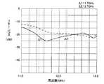
図2は、図3に示した比較例の一次放射器6´と、本発明の実施形態の一次放射器6とについて反射損失特性を測定した結果を示したグラフである。図3に示した比較例の一次放射器6´は、図1に示した一次放射器6からステップ7を取り除いたものであり、その他は図1に示した一次放射器と同様に構成されている。 FIG. 2 is a graph showing the results of measuring the reflection loss characteristics of the
図2において、実線で示した曲線は図1に示した一次放射器の反射損失(リターンロス)を周波数に対して示した反射損失特性であり、破線で示した曲線は、図3に示した比較例の反射損失特性である。図2においてΔ1及びΔ2はそれぞれ受信帯域の下限(11.7GHz)及び上限(12.7GHz)の周波数を示している。 In FIG. 2, the curve shown by the solid line is the reflection loss characteristic showing the return loss of the primary radiator shown in FIG. 1 with respect to the frequency, and the curve shown by the broken line is shown in FIG. It is the reflection loss characteristic of a comparative example. In FIG. 2, Δ1 and Δ2 indicate the lower limit (11.7 GHz) and upper limit (12.7 GHz) frequencies of the reception band, respectively.
なおリターンロスは、一次放射器に入射した電波に対して、反射により失われて受信されなかった電波が占める割合をデシベルで示したもので、入射した電波のすべてが反射により失われた場合を0dBとし、入射した電波のすべてが受信された場合を−∞dBとしている。衛星放送受信用のパラボラアンテナに用いる一次放射器の反射損失の許容上限値は、通常リターンロスで−20dBとされている。 Return loss is the decibel of the proportion of radio waves incident on the primary radiator that are lost due to reflection and not received, and the case where all of the incident radio waves are lost due to reflection. 0 dB, and −∞ dB when all incident radio waves are received. The allowable upper limit of the reflection loss of the primary radiator used for the satellite dish receiving parabolic antenna is normally -20 dB in terms of return loss.
図2から明らかなように、衛星放送の電波受信帯域(11.7GHz〜12.7GHz)においては、図3に示す比較例の一次放射器のリターンロスが約−15dBであったのに対し、図1に示す本発明の実施形態によった場合には、リターンロスが約−21dBまで改善され、反射損失が許容上限値以下に抑えらた。 As is clear from FIG. 2, in the radio wave reception band of satellite broadcasting (11.7 GHz to 12.7 GHz), the return loss of the primary radiator of the comparative example shown in FIG. 3 was about −15 dB. According to the embodiment of the present invention shown in FIG. 1, the return loss is improved to about −21 dB, and the reflection loss is suppressed to the allowable upper limit value or less.
上記の実験結果から、本発明のように放射器本体の内面にステップを設けることにより、防水カバーを大きく突出させることなく、十分に実用に耐える一次放射器が得られることが確認された。 From the above experimental results, it was confirmed that by providing a step on the inner surface of the radiator main body as in the present invention, a primary radiator that can sufficiently withstand practical use can be obtained without causing the waterproof cover to protrude greatly.
なお、図2によると、周波数帯域によっては、図3に示す比較例の方が優れた反射損失特性を示しているが、比較例の方が優れた反射損失特性を示す周波数帯域は、衛星放送の受信帯域を外れた帯域であり、受信帯域内では本発明による一次放射器の方が優れた反射特性を示す。 Note that, according to FIG. 2, the comparative example shown in FIG. 3 shows better reflection loss characteristics depending on the frequency band, but the comparative example shows better reflection loss characteristics in the satellite broadcast. The primary radiator according to the present invention exhibits better reflection characteristics within the reception band.
実際の設計に当たっては、防水カバー4の誘電率、厚さ、大きさ、形状等によって防水カバーで反射される電波の量が微妙に変化するので、受信帯域(11.7GHz〜12.7GHz)において反射損失をできるだけ小さくするように、実験に基づいてステップ7の大きさや位置を調整する。 In actual design, the amount of radio waves reflected by the waterproof cover varies slightly depending on the dielectric constant, thickness, size, shape, etc. of the
以上のように、本発明によれば、放射器本体3の内面にステップ7を設けて、該ステップで電波を反射させることにより防水カバー4で反射した電波をキャンセルするようにしたため、防水カバー4の突出長を長くすることなく、反射損失の低減を図ることができる。 As described above, according to the present invention, the
また上記のように構成すると、防水カバー4の内側に突出部を形成する必要がないため、防水カバーの厚みを均一にして、防水カバーの射出成形時にその外面にへこみが形成されるのを防ぐことができ、防水カバー4に雪が堆積する箇所が生じるのを防ぐことができる。 Moreover, since it is not necessary to form a protrusion part inside the
更に上記のように、放射器本体の内面にステップを設けて、防水カバーで生じた反射波をステップで反射した電波によりキャンセルすることによって反射損失の低減を図るようにすると、放射器本体内に誘電体からなる反射防止部材を設ける必要がないため、誘電損失を増大させたり、コストの上昇を招いたりすることなく、反射損失の低減を図ることができる。 Further, as described above, if a step is provided on the inner surface of the radiator body and the reflected wave generated by the waterproof cover is canceled by the radio wave reflected by the step, the reflection loss is reduced. Since there is no need to provide an antireflection member made of a dielectric, it is possible to reduce the reflection loss without increasing the dielectric loss or causing an increase in cost.
また上記のように、導波管1を円形導波管で構成して放射器本体3をその中心軸線に対して回転対称な形状とし、該放射器本体の中心軸線に対してステップ7を回転対称な形で設けると、円偏波軸比(一次放射器をその中心軸線を中心として回転させて取り付け角度を90°異ならせた場合の受信出力の最大値と最小値との比)を1とすることができるため、一次放射器の取り付け角度の影響を受けることなく所定の受信出力を得ることができる。 Further, as described above, the
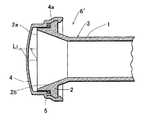
図4は、本発明に係るパラボラアンテナ用一次放射器の第2の実施形態を示した縦断面図で、この実施形態では、導波管1とホーン部2とからなる放射器本体3を製造する際に、そのホーン部2の内面にステップ7が一体に形成されている。導波管1及びホーン部2の材質、形状、ステップの配設位置、ステップの寸法などは図1に示した実施形態と同様である。 FIG. 4 is a longitudinal sectional view showing a second embodiment of a parabolic antenna primary radiator according to the present invention. In this embodiment, a radiator main body 3 including a
このようにステップ7をホーン部2の内面に一体に設けると、放射器本体3をダイカスト成形する際に用いる金型の一部にステップ7を成形するための型部を設けておくだけでステップ7を成形することができるため、ステップを備えた放射器本体の製造を簡単にすることができる。 When
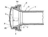
図5は、本発明に係るパラボラアンテナ用一次放射器の第3の実施形態を示した縦断面図で、この実施形態では、ステップ7が放射器本体3の導波管1とホーン部2との境界部に、導波管1と一体に設けられている。その他の点は図1に示した実施形態と同様である。 FIG. 5 is a longitudinal sectional view showing a third embodiment of a primary radiator for a parabolic antenna according to the present invention. In this embodiment,
このように、ステップ7を定位置に設ける場合には、防水カバー4の内面とホーン部2の開口端2aとの間の距離L1を調整することにより、防水カバー4の内面とステップ7との間の距離を、放射器本体内を伝搬する電波の位相角に換算して180°の奇数倍にほぼ等しくするように調整するとともに、ステップ7の寸法を適当な値に調整することにより、防水カバーにより反射された電波がステップ7で反射した電波によりキャンセルされるようにする。このように構成した場合でも、防水カバー4の内面とホーン部2の開口端2aとの間の距離L1を長くすることなく、反射損失の低減を図ることができる。 In this way, when
製造された一次放射器を出荷する際には、その特性が規格を充たしているか否かを検査する必要がある。一次放射器の検査を行う際には、導波管1内にアダプタ導波管を挿入して、該アダプタ導波管の一端を導波管1とホーン部2との間の境界部に接触抵抗を十分に小さくした状態で接触させる必要がある。従来の一次放射器では、導波管1とホーン部2との境界部が1本の環状線として存在していたため、アダプタ導波管が傾斜した状態で挿入された際に、アダプタ導波管と上記境界部とが接触しない箇所が生じ、測定精度が悪くなることがあった。 When the manufactured primary radiator is shipped, it is necessary to inspect whether or not the characteristics satisfy the standard. When inspecting the primary radiator, an adapter waveguide is inserted into the
これに対し、図5に示したようにステップを導波管1とホーン部2との境界部に設けると、アダプタ導波管の一端をステップ7に接触させることにより、一次放射器の導波管とホーン部との境界部とアダプタ導波管とを面接触させることができるため、アダプタ導波管と一次放射器との接触不良により測定精度が低下するのを防ぐことができる。 On the other hand, when a step is provided at the boundary between the
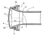
図6は、本発明の第4の実施形態を示している。第1ないし第3の実施形態では、ステップ部が放射器本体のホーン部2の内面、または導波管とホーン部との境界部に形成されているが、図6に示した第4の実施形態では、導波管1の内面にステップ7が設けられている。このようにステップ7を設ける場合にも、防水カバー4で反射した電波とステップ7で反射した電波とがキャンセルし合うように、防水カバー4の内面とステップ7との間の距離L2を、電波の位相に換算して180°の奇数倍にほぼ等しく設定し、ステップ7で反射する電波の量を防水カバー4で反射する電波の量にほぼ等しくするように、ステップ7の寸法(最大外径D1及び内径D2)を設定することにより、反射損失の低減を図ることができる。 FIG. 6 shows a fourth embodiment of the present invention. In the first to third embodiments, the step portion is formed on the inner surface of the
図7は本発明の第5の実施形態を示したものである。第1ないし第5の実施形態では、ステップ7が、その段差部(導波管の中心軸線と直交する面)をホーン部2の開口端側に向けた状態で設けられていたが、ステップ7は、該ステップの部分でインピーダンスを急に変化させて、防水カバー4側から導波管1側に伝搬する電波を反射させるように設ければよいため、図7に示すように、段差部を導波管1側に向けた状態でステップ7を設けるようにしてもよい。 FIG. 7 shows a fifth embodiment of the present invention. In the first to fifth embodiments,
上記の実施形態では、12GHz帯の電波を受信するとしたが、他の周波数帯の電波を受信するパラボラアンテナ用一次放射器にも本発明を適用できるのはもちろんである。本発明は、受信する電波の周波数帯によって限定されることはない。 In the above embodiment, it is assumed that radio waves in the 12 GHz band are received, but it is needless to say that the present invention can also be applied to parabolic antenna primary radiators that receive radio waves in other frequency bands. The present invention is not limited by the frequency band of the received radio wave.
1 導波管
2 ホーン部
3 放射器本体
4 防水カバー
6 一次放射器
7 ステップ1
Claims (6)
Translated fromJapanese前記放射器本体の内面に反射損失低減用のステップが設けられ、前記防水カバーと前記ステップとの間の距離が前記放射器本体内を伝搬する電波の位相角に換算して180°の奇数倍にほぼ等しく設定されて、前記放射器本体内で発生する反射損失を許容上限値以下に抑えるように前記ステップの寸法が設定されているパラボラアンテナ用一次放射器。A primary radiator for a parabolic antenna comprising a waveguide, a radiator main body having a horn portion provided on one end side of the waveguide, and a waterproof cover covering an opening end of the horn portion,
A step for reducing reflection loss is provided on the inner surface of the radiator body, and the distance between the waterproof cover and the step isan odd multiple of 180 ° in terms of the phase angle of the radio wave propagating in the radiator body. The parabolic antenna primary radiator isset so as to be substantially equalto the above and the size of the step is setso as tosuppress the reflection loss generated in the radiator body to an allowable upper limit value or less.
Priority Applications (5)
| Application Number | Priority Date | Filing Date | Title |
|---|---|---|---|
| JP2004114523AJP4000359B2 (en) | 2003-05-13 | 2004-04-08 | Primary radiator for parabolic antenna |
| US10/843,244US7027003B2 (en) | 2003-05-13 | 2004-05-11 | Primary radiator for parabolic antenna |
| CA002466972ACA2466972A1 (en) | 2003-05-13 | 2004-05-12 | Primary radiator for parabolic antenna |
| EP04252773AEP1478050B1 (en) | 2003-05-13 | 2004-05-13 | Primary radiator for parabolic antenna |
| DE602004007063TDE602004007063T2 (en) | 2003-05-13 | 2004-05-13 | Primary radiator for a parabolic antenna |
Applications Claiming Priority (2)
| Application Number | Priority Date | Filing Date | Title |
|---|---|---|---|
| JP2003134144 | 2003-05-13 | ||
| JP2004114523AJP4000359B2 (en) | 2003-05-13 | 2004-04-08 | Primary radiator for parabolic antenna |
Publications (3)
| Publication Number | Publication Date |
|---|---|
| JP2004364264A JP2004364264A (en) | 2004-12-24 |
| JP2004364264A5 JP2004364264A5 (en) | 2005-09-15 |
| JP4000359B2true JP4000359B2 (en) | 2007-10-31 |
Family
ID=33032385
Family Applications (1)
| Application Number | Title | Priority Date | Filing Date |
|---|---|---|---|
| JP2004114523AExpired - Fee RelatedJP4000359B2 (en) | 2003-05-13 | 2004-04-08 | Primary radiator for parabolic antenna |
Country Status (5)
| Country | Link |
|---|---|
| US (1) | US7027003B2 (en) |
| EP (1) | EP1478050B1 (en) |
| JP (1) | JP4000359B2 (en) |
| CA (1) | CA2466972A1 (en) |
| DE (1) | DE602004007063T2 (en) |
Cited By (1)
| Publication number | Priority date | Publication date | Assignee | Title |
|---|---|---|---|---|
| JP2012124814A (en)* | 2010-12-10 | 2012-06-28 | Sharp Corp | Satellite receiving converter device, manufacturing method thereof and performance measurement jig |
Families Citing this family (159)
| Publication number | Priority date | Publication date | Assignee | Title |
|---|---|---|---|---|
| WO2007047418A2 (en) | 2005-10-14 | 2007-04-26 | Bae Systems Information And Electronic Systems Integration Inc. | Through-the-wall motion detector with improved antenna |
| US8797207B2 (en)* | 2011-04-18 | 2014-08-05 | Vega Grieshaber Kg | Filling level measuring device antenna cover |
| DE102011083951A1 (en)* | 2011-10-04 | 2013-04-04 | Rohde & Schwarz Gmbh & Co. Kg | Force introduction ring for foamed radome |
| US10009065B2 (en) | 2012-12-05 | 2018-06-26 | At&T Intellectual Property I, L.P. | Backhaul link for distributed antenna system |
| US9113347B2 (en) | 2012-12-05 | 2015-08-18 | At&T Intellectual Property I, Lp | Backhaul link for distributed antenna system |
| US9525524B2 (en) | 2013-05-31 | 2016-12-20 | At&T Intellectual Property I, L.P. | Remote distributed antenna system |
| US9999038B2 (en) | 2013-05-31 | 2018-06-12 | At&T Intellectual Property I, L.P. | Remote distributed antenna system |
| US8897697B1 (en) | 2013-11-06 | 2014-11-25 | At&T Intellectual Property I, Lp | Millimeter-wave surface-wave communications |
| US9209902B2 (en) | 2013-12-10 | 2015-12-08 | At&T Intellectual Property I, L.P. | Quasi-optical coupler |
| TWI528637B (en)* | 2013-12-26 | 2016-04-01 | 啟碁科技股份有限公司 | Waterproof part |
| CN104752804A (en)* | 2013-12-31 | 2015-07-01 | 启碁科技股份有限公司 | Waterproof assembly |
| US9692101B2 (en) | 2014-08-26 | 2017-06-27 | At&T Intellectual Property I, L.P. | Guided wave couplers for coupling electromagnetic waves between a waveguide surface and a surface of a wire |
| US9768833B2 (en) | 2014-09-15 | 2017-09-19 | At&T Intellectual Property I, L.P. | Method and apparatus for sensing a condition in a transmission medium of electromagnetic waves |
| US10063280B2 (en) | 2014-09-17 | 2018-08-28 | At&T Intellectual Property I, L.P. | Monitoring and mitigating conditions in a communication network |
| US9615269B2 (en) | 2014-10-02 | 2017-04-04 | At&T Intellectual Property I, L.P. | Method and apparatus that provides fault tolerance in a communication network |
| US9685992B2 (en) | 2014-10-03 | 2017-06-20 | At&T Intellectual Property I, L.P. | Circuit panel network and methods thereof |
| US9503189B2 (en) | 2014-10-10 | 2016-11-22 | At&T Intellectual Property I, L.P. | Method and apparatus for arranging communication sessions in a communication system |
| US9762289B2 (en) | 2014-10-14 | 2017-09-12 | At&T Intellectual Property I, L.P. | Method and apparatus for transmitting or receiving signals in a transportation system |
| US9973299B2 (en) | 2014-10-14 | 2018-05-15 | At&T Intellectual Property I, L.P. | Method and apparatus for adjusting a mode of communication in a communication network |
| US9769020B2 (en) | 2014-10-21 | 2017-09-19 | At&T Intellectual Property I, L.P. | Method and apparatus for responding to events affecting communications in a communication network |
| US9627768B2 (en) | 2014-10-21 | 2017-04-18 | At&T Intellectual Property I, L.P. | Guided-wave transmission device with non-fundamental mode propagation and methods for use therewith |
| US9780834B2 (en) | 2014-10-21 | 2017-10-03 | At&T Intellectual Property I, L.P. | Method and apparatus for transmitting electromagnetic waves |
| US9653770B2 (en) | 2014-10-21 | 2017-05-16 | At&T Intellectual Property I, L.P. | Guided wave coupler, coupling module and methods for use therewith |
| US9577306B2 (en) | 2014-10-21 | 2017-02-21 | At&T Intellectual Property I, L.P. | Guided-wave transmission device and methods for use therewith |
| US9312919B1 (en) | 2014-10-21 | 2016-04-12 | At&T Intellectual Property I, Lp | Transmission device with impairment compensation and methods for use therewith |
| US9520945B2 (en) | 2014-10-21 | 2016-12-13 | At&T Intellectual Property I, L.P. | Apparatus for providing communication services and methods thereof |
| US10340573B2 (en) | 2016-10-26 | 2019-07-02 | At&T Intellectual Property I, L.P. | Launcher with cylindrical coupling device and methods for use therewith |
| US9954287B2 (en) | 2014-11-20 | 2018-04-24 | At&T Intellectual Property I, L.P. | Apparatus for converting wireless signals and electromagnetic waves and methods thereof |
| US9997819B2 (en) | 2015-06-09 | 2018-06-12 | At&T Intellectual Property I, L.P. | Transmission medium and method for facilitating propagation of electromagnetic waves via a core |
| US9461706B1 (en) | 2015-07-31 | 2016-10-04 | At&T Intellectual Property I, Lp | Method and apparatus for exchanging communication signals |
| US9742462B2 (en) | 2014-12-04 | 2017-08-22 | At&T Intellectual Property I, L.P. | Transmission medium and communication interfaces and methods for use therewith |
| US10243784B2 (en) | 2014-11-20 | 2019-03-26 | At&T Intellectual Property I, L.P. | System for generating topology information and methods thereof |
| US9800327B2 (en) | 2014-11-20 | 2017-10-24 | At&T Intellectual Property I, L.P. | Apparatus for controlling operations of a communication device and methods thereof |
| US9544006B2 (en) | 2014-11-20 | 2017-01-10 | At&T Intellectual Property I, L.P. | Transmission device with mode division multiplexing and methods for use therewith |
| US9680670B2 (en) | 2014-11-20 | 2017-06-13 | At&T Intellectual Property I, L.P. | Transmission device with channel equalization and control and methods for use therewith |
| US9654173B2 (en) | 2014-11-20 | 2017-05-16 | At&T Intellectual Property I, L.P. | Apparatus for powering a communication device and methods thereof |
| US10009067B2 (en) | 2014-12-04 | 2018-06-26 | At&T Intellectual Property I, L.P. | Method and apparatus for configuring a communication interface |
| US10144036B2 (en) | 2015-01-30 | 2018-12-04 | At&T Intellectual Property I, L.P. | Method and apparatus for mitigating interference affecting a propagation of electromagnetic waves guided by a transmission medium |
| US9876570B2 (en) | 2015-02-20 | 2018-01-23 | At&T Intellectual Property I, Lp | Guided-wave transmission device with non-fundamental mode propagation and methods for use therewith |
| US9749013B2 (en) | 2015-03-17 | 2017-08-29 | At&T Intellectual Property I, L.P. | Method and apparatus for reducing attenuation of electromagnetic waves guided by a transmission medium |
| US10224981B2 (en) | 2015-04-24 | 2019-03-05 | At&T Intellectual Property I, Lp | Passive electrical coupling device and methods for use therewith |
| US9705561B2 (en) | 2015-04-24 | 2017-07-11 | At&T Intellectual Property I, L.P. | Directional coupling device and methods for use therewith |
| US9793954B2 (en) | 2015-04-28 | 2017-10-17 | At&T Intellectual Property I, L.P. | Magnetic coupling device and methods for use therewith |
| US9948354B2 (en) | 2015-04-28 | 2018-04-17 | At&T Intellectual Property I, L.P. | Magnetic coupling device with reflective plate and methods for use therewith |
| US9748626B2 (en) | 2015-05-14 | 2017-08-29 | At&T Intellectual Property I, L.P. | Plurality of cables having different cross-sectional shapes which are bundled together to form a transmission medium |
| US9490869B1 (en) | 2015-05-14 | 2016-11-08 | At&T Intellectual Property I, L.P. | Transmission medium having multiple cores and methods for use therewith |
| US9871282B2 (en) | 2015-05-14 | 2018-01-16 | At&T Intellectual Property I, L.P. | At least one transmission medium having a dielectric surface that is covered at least in part by a second dielectric |
| US10650940B2 (en) | 2015-05-15 | 2020-05-12 | At&T Intellectual Property I, L.P. | Transmission medium having a conductive material and methods for use therewith |
| US9917341B2 (en) | 2015-05-27 | 2018-03-13 | At&T Intellectual Property I, L.P. | Apparatus and method for launching electromagnetic waves and for modifying radial dimensions of the propagating electromagnetic waves |
| US10812174B2 (en) | 2015-06-03 | 2020-10-20 | At&T Intellectual Property I, L.P. | Client node device and methods for use therewith |
| US10103801B2 (en) | 2015-06-03 | 2018-10-16 | At&T Intellectual Property I, L.P. | Host node device and methods for use therewith |
| US9912381B2 (en) | 2015-06-03 | 2018-03-06 | At&T Intellectual Property I, Lp | Network termination and methods for use therewith |
| US9866309B2 (en) | 2015-06-03 | 2018-01-09 | At&T Intellectual Property I, Lp | Host node device and methods for use therewith |
| US9913139B2 (en) | 2015-06-09 | 2018-03-06 | At&T Intellectual Property I, L.P. | Signal fingerprinting for authentication of communicating devices |
| US9608692B2 (en) | 2015-06-11 | 2017-03-28 | At&T Intellectual Property I, L.P. | Repeater and methods for use therewith |
| US10142086B2 (en) | 2015-06-11 | 2018-11-27 | At&T Intellectual Property I, L.P. | Repeater and methods for use therewith |
| US9820146B2 (en) | 2015-06-12 | 2017-11-14 | At&T Intellectual Property I, L.P. | Method and apparatus for authentication and identity management of communicating devices |
| US9667317B2 (en) | 2015-06-15 | 2017-05-30 | At&T Intellectual Property I, L.P. | Method and apparatus for providing security using network traffic adjustments |
| US9640850B2 (en) | 2015-06-25 | 2017-05-02 | At&T Intellectual Property I, L.P. | Methods and apparatus for inducing a non-fundamental wave mode on a transmission medium |
| US9865911B2 (en) | 2015-06-25 | 2018-01-09 | At&T Intellectual Property I, L.P. | Waveguide system for slot radiating first electromagnetic waves that are combined into a non-fundamental wave mode second electromagnetic wave on a transmission medium |
| US9509415B1 (en) | 2015-06-25 | 2016-11-29 | At&T Intellectual Property I, L.P. | Methods and apparatus for inducing a fundamental wave mode on a transmission medium |
| US10170840B2 (en) | 2015-07-14 | 2019-01-01 | At&T Intellectual Property I, L.P. | Apparatus and methods for sending or receiving electromagnetic signals |
| US9628116B2 (en) | 2015-07-14 | 2017-04-18 | At&T Intellectual Property I, L.P. | Apparatus and methods for transmitting wireless signals |
| US9836957B2 (en) | 2015-07-14 | 2017-12-05 | At&T Intellectual Property I, L.P. | Method and apparatus for communicating with premises equipment |
| US10205655B2 (en) | 2015-07-14 | 2019-02-12 | At&T Intellectual Property I, L.P. | Apparatus and methods for communicating utilizing an antenna array and multiple communication paths |
| US10341142B2 (en) | 2015-07-14 | 2019-07-02 | At&T Intellectual Property I, L.P. | Apparatus and methods for generating non-interfering electromagnetic waves on an uninsulated conductor |
| US10320586B2 (en) | 2015-07-14 | 2019-06-11 | At&T Intellectual Property I, L.P. | Apparatus and methods for generating non-interfering electromagnetic waves on an insulated transmission medium |
| US9853342B2 (en) | 2015-07-14 | 2017-12-26 | At&T Intellectual Property I, L.P. | Dielectric transmission medium connector and methods for use therewith |
| US9722318B2 (en) | 2015-07-14 | 2017-08-01 | At&T Intellectual Property I, L.P. | Method and apparatus for coupling an antenna to a device |
| US10033107B2 (en) | 2015-07-14 | 2018-07-24 | At&T Intellectual Property I, L.P. | Method and apparatus for coupling an antenna to a device |
| US10033108B2 (en) | 2015-07-14 | 2018-07-24 | At&T Intellectual Property I, L.P. | Apparatus and methods for generating an electromagnetic wave having a wave mode that mitigates interference |
| US9882257B2 (en) | 2015-07-14 | 2018-01-30 | At&T Intellectual Property I, L.P. | Method and apparatus for launching a wave mode that mitigates interference |
| US10148016B2 (en) | 2015-07-14 | 2018-12-04 | At&T Intellectual Property I, L.P. | Apparatus and methods for communicating utilizing an antenna array |
| US10044409B2 (en) | 2015-07-14 | 2018-08-07 | At&T Intellectual Property I, L.P. | Transmission medium and methods for use therewith |
| US9847566B2 (en) | 2015-07-14 | 2017-12-19 | At&T Intellectual Property I, L.P. | Method and apparatus for adjusting a field of a signal to mitigate interference |
| US9608740B2 (en) | 2015-07-15 | 2017-03-28 | At&T Intellectual Property I, L.P. | Method and apparatus for launching a wave mode that mitigates interference |
| US10090606B2 (en) | 2015-07-15 | 2018-10-02 | At&T Intellectual Property I, L.P. | Antenna system with dielectric array and methods for use therewith |
| US9793951B2 (en) | 2015-07-15 | 2017-10-17 | At&T Intellectual Property I, L.P. | Method and apparatus for launching a wave mode that mitigates interference |
| US9871283B2 (en) | 2015-07-23 | 2018-01-16 | At&T Intellectual Property I, Lp | Transmission medium having a dielectric core comprised of plural members connected by a ball and socket configuration |
| US9948333B2 (en) | 2015-07-23 | 2018-04-17 | At&T Intellectual Property I, L.P. | Method and apparatus for wireless communications to mitigate interference |
| US9912027B2 (en) | 2015-07-23 | 2018-03-06 | At&T Intellectual Property I, L.P. | Method and apparatus for exchanging communication signals |
| US10784670B2 (en) | 2015-07-23 | 2020-09-22 | At&T Intellectual Property I, L.P. | Antenna support for aligning an antenna |
| US9749053B2 (en) | 2015-07-23 | 2017-08-29 | At&T Intellectual Property I, L.P. | Node device, repeater and methods for use therewith |
| US10020587B2 (en) | 2015-07-31 | 2018-07-10 | At&T Intellectual Property I, L.P. | Radial antenna and methods for use therewith |
| US9735833B2 (en) | 2015-07-31 | 2017-08-15 | At&T Intellectual Property I, L.P. | Method and apparatus for communications management in a neighborhood network |
| US9967173B2 (en) | 2015-07-31 | 2018-05-08 | At&T Intellectual Property I, L.P. | Method and apparatus for authentication and identity management of communicating devices |
| US9904535B2 (en) | 2015-09-14 | 2018-02-27 | At&T Intellectual Property I, L.P. | Method and apparatus for distributing software |
| US10136434B2 (en) | 2015-09-16 | 2018-11-20 | At&T Intellectual Property I, L.P. | Method and apparatus for use with a radio distributed antenna system having an ultra-wideband control channel |
| US10009901B2 (en) | 2015-09-16 | 2018-06-26 | At&T Intellectual Property I, L.P. | Method, apparatus, and computer-readable storage medium for managing utilization of wireless resources between base stations |
| US10079661B2 (en) | 2015-09-16 | 2018-09-18 | At&T Intellectual Property I, L.P. | Method and apparatus for use with a radio distributed antenna system having a clock reference |
| US10009063B2 (en) | 2015-09-16 | 2018-06-26 | At&T Intellectual Property I, L.P. | Method and apparatus for use with a radio distributed antenna system having an out-of-band reference signal |
| US9769128B2 (en) | 2015-09-28 | 2017-09-19 | At&T Intellectual Property I, L.P. | Method and apparatus for encryption of communications over a network |
| US9729197B2 (en) | 2015-10-01 | 2017-08-08 | At&T Intellectual Property I, L.P. | Method and apparatus for communicating network management traffic over a network |
| US9882277B2 (en) | 2015-10-02 | 2018-01-30 | At&T Intellectual Property I, Lp | Communication device and antenna assembly with actuated gimbal mount |
| US9876264B2 (en) | 2015-10-02 | 2018-01-23 | At&T Intellectual Property I, Lp | Communication system, guided wave switch and methods for use therewith |
| US10665942B2 (en) | 2015-10-16 | 2020-05-26 | At&T Intellectual Property I, L.P. | Method and apparatus for adjusting wireless communications |
| US10355367B2 (en) | 2015-10-16 | 2019-07-16 | At&T Intellectual Property I, L.P. | Antenna structure for exchanging wireless signals |
| US9912419B1 (en) | 2016-08-24 | 2018-03-06 | At&T Intellectual Property I, L.P. | Method and apparatus for managing a fault in a distributed antenna system |
| US9860075B1 (en) | 2016-08-26 | 2018-01-02 | At&T Intellectual Property I, L.P. | Method and communication node for broadband distribution |
| US10291311B2 (en) | 2016-09-09 | 2019-05-14 | At&T Intellectual Property I, L.P. | Method and apparatus for mitigating a fault in a distributed antenna system |
| US11032819B2 (en) | 2016-09-15 | 2021-06-08 | At&T Intellectual Property I, L.P. | Method and apparatus for use with a radio distributed antenna system having a control channel reference signal |
| US10135147B2 (en) | 2016-10-18 | 2018-11-20 | At&T Intellectual Property I, L.P. | Apparatus and methods for launching guided waves via an antenna |
| US10135146B2 (en) | 2016-10-18 | 2018-11-20 | At&T Intellectual Property I, L.P. | Apparatus and methods for launching guided waves via circuits |
| US10340600B2 (en) | 2016-10-18 | 2019-07-02 | At&T Intellectual Property I, L.P. | Apparatus and methods for launching guided waves via plural waveguide systems |
| US9991580B2 (en) | 2016-10-21 | 2018-06-05 | At&T Intellectual Property I, L.P. | Launcher and coupling system for guided wave mode cancellation |
| US9876605B1 (en) | 2016-10-21 | 2018-01-23 | At&T Intellectual Property I, L.P. | Launcher and coupling system to support desired guided wave mode |
| US10811767B2 (en) | 2016-10-21 | 2020-10-20 | At&T Intellectual Property I, L.P. | System and dielectric antenna with convex dielectric radome |
| US10374316B2 (en) | 2016-10-21 | 2019-08-06 | At&T Intellectual Property I, L.P. | System and dielectric antenna with non-uniform dielectric |
| US10312567B2 (en) | 2016-10-26 | 2019-06-04 | At&T Intellectual Property I, L.P. | Launcher with planar strip antenna and methods for use therewith |
| US10224634B2 (en) | 2016-11-03 | 2019-03-05 | At&T Intellectual Property I, L.P. | Methods and apparatus for adjusting an operational characteristic of an antenna |
| US10498044B2 (en) | 2016-11-03 | 2019-12-03 | At&T Intellectual Property I, L.P. | Apparatus for configuring a surface of an antenna |
| US10225025B2 (en) | 2016-11-03 | 2019-03-05 | At&T Intellectual Property I, L.P. | Method and apparatus for detecting a fault in a communication system |
| US10291334B2 (en) | 2016-11-03 | 2019-05-14 | At&T Intellectual Property I, L.P. | System for detecting a fault in a communication system |
| US10340601B2 (en) | 2016-11-23 | 2019-07-02 | At&T Intellectual Property I, L.P. | Multi-antenna system and methods for use therewith |
| US10090594B2 (en) | 2016-11-23 | 2018-10-02 | At&T Intellectual Property I, L.P. | Antenna system having structural configurations for assembly |
| US10535928B2 (en) | 2016-11-23 | 2020-01-14 | At&T Intellectual Property I, L.P. | Antenna system and methods for use therewith |
| US10340603B2 (en) | 2016-11-23 | 2019-07-02 | At&T Intellectual Property I, L.P. | Antenna system having shielded structural configurations for assembly |
| US10178445B2 (en) | 2016-11-23 | 2019-01-08 | At&T Intellectual Property I, L.P. | Methods, devices, and systems for load balancing between a plurality of waveguides |
| US10361489B2 (en) | 2016-12-01 | 2019-07-23 | At&T Intellectual Property I, L.P. | Dielectric dish antenna system and methods for use therewith |
| US10305190B2 (en) | 2016-12-01 | 2019-05-28 | At&T Intellectual Property I, L.P. | Reflecting dielectric antenna system and methods for use therewith |
| US10819035B2 (en) | 2016-12-06 | 2020-10-27 | At&T Intellectual Property I, L.P. | Launcher with helical antenna and methods for use therewith |
| US10694379B2 (en) | 2016-12-06 | 2020-06-23 | At&T Intellectual Property I, L.P. | Waveguide system with device-based authentication and methods for use therewith |
| US10727599B2 (en) | 2016-12-06 | 2020-07-28 | At&T Intellectual Property I, L.P. | Launcher with slot antenna and methods for use therewith |
| US10382976B2 (en) | 2016-12-06 | 2019-08-13 | At&T Intellectual Property I, L.P. | Method and apparatus for managing wireless communications based on communication paths and network device positions |
| US10637149B2 (en) | 2016-12-06 | 2020-04-28 | At&T Intellectual Property I, L.P. | Injection molded dielectric antenna and methods for use therewith |
| US10020844B2 (en) | 2016-12-06 | 2018-07-10 | T&T Intellectual Property I, L.P. | Method and apparatus for broadcast communication via guided waves |
| US10755542B2 (en) | 2016-12-06 | 2020-08-25 | At&T Intellectual Property I, L.P. | Method and apparatus for surveillance via guided wave communication |
| US10439675B2 (en) | 2016-12-06 | 2019-10-08 | At&T Intellectual Property I, L.P. | Method and apparatus for repeating guided wave communication signals |
| US10326494B2 (en) | 2016-12-06 | 2019-06-18 | At&T Intellectual Property I, L.P. | Apparatus for measurement de-embedding and methods for use therewith |
| US10135145B2 (en) | 2016-12-06 | 2018-11-20 | At&T Intellectual Property I, L.P. | Apparatus and methods for generating an electromagnetic wave along a transmission medium |
| US9927517B1 (en) | 2016-12-06 | 2018-03-27 | At&T Intellectual Property I, L.P. | Apparatus and methods for sensing rainfall |
| US10389029B2 (en) | 2016-12-07 | 2019-08-20 | At&T Intellectual Property I, L.P. | Multi-feed dielectric antenna system with core selection and methods for use therewith |
| US10139820B2 (en) | 2016-12-07 | 2018-11-27 | At&T Intellectual Property I, L.P. | Method and apparatus for deploying equipment of a communication system |
| US10168695B2 (en) | 2016-12-07 | 2019-01-01 | At&T Intellectual Property I, L.P. | Method and apparatus for controlling an unmanned aircraft |
| US10027397B2 (en) | 2016-12-07 | 2018-07-17 | At&T Intellectual Property I, L.P. | Distributed antenna system and methods for use therewith |
| US10243270B2 (en) | 2016-12-07 | 2019-03-26 | At&T Intellectual Property I, L.P. | Beam adaptive multi-feed dielectric antenna system and methods for use therewith |
| US10547348B2 (en) | 2016-12-07 | 2020-01-28 | At&T Intellectual Property I, L.P. | Method and apparatus for switching transmission mediums in a communication system |
| US10359749B2 (en) | 2016-12-07 | 2019-07-23 | At&T Intellectual Property I, L.P. | Method and apparatus for utilities management via guided wave communication |
| US9893795B1 (en) | 2016-12-07 | 2018-02-13 | At&T Intellectual Property I, Lp | Method and repeater for broadband distribution |
| US10446936B2 (en) | 2016-12-07 | 2019-10-15 | At&T Intellectual Property I, L.P. | Multi-feed dielectric antenna system and methods for use therewith |
| US10601494B2 (en) | 2016-12-08 | 2020-03-24 | At&T Intellectual Property I, L.P. | Dual-band communication device and method for use therewith |
| US10069535B2 (en) | 2016-12-08 | 2018-09-04 | At&T Intellectual Property I, L.P. | Apparatus and methods for launching electromagnetic waves having a certain electric field structure |
| US9911020B1 (en) | 2016-12-08 | 2018-03-06 | At&T Intellectual Property I, L.P. | Method and apparatus for tracking via a radio frequency identification device |
| US10389037B2 (en) | 2016-12-08 | 2019-08-20 | At&T Intellectual Property I, L.P. | Apparatus and methods for selecting sections of an antenna array and use therewith |
| US10777873B2 (en) | 2016-12-08 | 2020-09-15 | At&T Intellectual Property I, L.P. | Method and apparatus for mounting network devices |
| US10326689B2 (en) | 2016-12-08 | 2019-06-18 | At&T Intellectual Property I, L.P. | Method and system for providing alternative communication paths |
| US10530505B2 (en) | 2016-12-08 | 2020-01-07 | At&T Intellectual Property I, L.P. | Apparatus and methods for launching electromagnetic waves along a transmission medium |
| US10916969B2 (en) | 2016-12-08 | 2021-02-09 | At&T Intellectual Property I, L.P. | Method and apparatus for providing power using an inductive coupling |
| US10411356B2 (en) | 2016-12-08 | 2019-09-10 | At&T Intellectual Property I, L.P. | Apparatus and methods for selectively targeting communication devices with an antenna array |
| US9998870B1 (en) | 2016-12-08 | 2018-06-12 | At&T Intellectual Property I, L.P. | Method and apparatus for proximity sensing |
| US10938108B2 (en) | 2016-12-08 | 2021-03-02 | At&T Intellectual Property I, L.P. | Frequency selective multi-feed dielectric antenna system and methods for use therewith |
| US10103422B2 (en) | 2016-12-08 | 2018-10-16 | At&T Intellectual Property I, L.P. | Method and apparatus for mounting network devices |
| US10264586B2 (en) | 2016-12-09 | 2019-04-16 | At&T Mobility Ii Llc | Cloud-based packet controller and methods for use therewith |
| US10340983B2 (en) | 2016-12-09 | 2019-07-02 | At&T Intellectual Property I, L.P. | Method and apparatus for surveying remote sites via guided wave communications |
| US9838896B1 (en) | 2016-12-09 | 2017-12-05 | At&T Intellectual Property I, L.P. | Method and apparatus for assessing network coverage |
| US9973940B1 (en) | 2017-02-27 | 2018-05-15 | At&T Intellectual Property I, L.P. | Apparatus and methods for dynamic impedance matching of a guided wave launcher |
| US10298293B2 (en) | 2017-03-13 | 2019-05-21 | At&T Intellectual Property I, L.P. | Apparatus of communication utilizing wireless network devices |
| TWI663786B (en)* | 2017-11-20 | 2019-06-21 | 啓碁科技股份有限公司 | Horn antenna and antenna cover thereof |
| US11888222B1 (en)* | 2022-09-23 | 2024-01-30 | The Boeing Company | Flange for 3D printed antennas and related methods |
Family Cites Families (17)
| Publication number | Priority date | Publication date | Assignee | Title |
|---|---|---|---|---|
| US2283935A (en)* | 1938-04-29 | 1942-05-26 | Bell Telephone Labor Inc | Transmission, radiation, and reception of electromagnetic waves |
| US4122446A (en)* | 1977-04-28 | 1978-10-24 | Andrew Corporation | Dual mode feed horn |
| US4533919A (en)* | 1983-10-14 | 1985-08-06 | At&T Bell Laboratories | Corrugated antenna feed arrangement |
| FR2607968B1 (en)* | 1986-12-09 | 1989-02-03 | Alcatel Thomson Faisceaux | SOURCE OF ILLUMINATION FOR TELECOMMUNICATIONS ANTENNA |
| US5642121A (en)* | 1993-03-16 | 1997-06-24 | Innova Corporation | High-gain, waveguide-fed antenna having controllable higher order mode phasing |
| JP3239030B2 (en) | 1994-12-14 | 2001-12-17 | シャープ株式会社 | Primary radiator for parabolic antenna |
| JP3277755B2 (en)* | 1995-05-29 | 2002-04-22 | 松下電器産業株式会社 | Helical primary radiators and converters |
| US5767815A (en)* | 1996-06-20 | 1998-06-16 | Andrew Corporation | Antenna feedhorn with protective window |
| JP3214548B2 (en)* | 1997-04-09 | 2001-10-02 | 日本電気株式会社 | Lens antenna |
| US6163304A (en)* | 1999-03-16 | 2000-12-19 | Trw Inc. | Multimode, multi-step antenna feed horn |
| US6501432B2 (en)* | 2000-08-11 | 2002-12-31 | Alps Electric Co., Ltd. | Primary radiator capable of achieving both low reflection and low loss |
| US6573873B2 (en)* | 2001-06-08 | 2003-06-03 | Lockheed Martin Corporation | Stepped horn with dielectric loading |
| JP3472567B2 (en) | 2001-06-26 | 2003-12-02 | 株式会社日立国際電気 | Primary radiator for satellite dish and converter for satellite broadcasting reception |
| JP3784715B2 (en)* | 2001-12-26 | 2006-06-14 | シャープ株式会社 | Feed horn structure, manufacturing method thereof, converter and antenna for satellite communication reception |
| JP3857178B2 (en) | 2002-04-30 | 2006-12-13 | シャープ株式会社 | Primary radiator for parabolic antenna |
| JP3910880B2 (en)* | 2002-05-30 | 2007-04-25 | シャープ株式会社 | Satellite communication receiving converter feed horn, method for manufacturing the same, and satellite communication receiving converter |
| US20040222934A1 (en)* | 2003-05-06 | 2004-11-11 | Northrop Grumman Corporation | Multi-mode, multi-choke feed horn |
- 2004
- 2004-04-08JPJP2004114523Apatent/JP4000359B2/ennot_activeExpired - Fee Related
- 2004-05-11USUS10/843,244patent/US7027003B2/ennot_activeExpired - Fee Related
- 2004-05-12CACA002466972Apatent/CA2466972A1/ennot_activeAbandoned
- 2004-05-13DEDE602004007063Tpatent/DE602004007063T2/ennot_activeExpired - Fee Related
- 2004-05-13EPEP04252773Apatent/EP1478050B1/ennot_activeExpired - Lifetime
Cited By (1)
| Publication number | Priority date | Publication date | Assignee | Title |
|---|---|---|---|---|
| JP2012124814A (en)* | 2010-12-10 | 2012-06-28 | Sharp Corp | Satellite receiving converter device, manufacturing method thereof and performance measurement jig |
Also Published As
| Publication number | Publication date |
|---|---|
| EP1478050A1 (en) | 2004-11-17 |
| JP2004364264A (en) | 2004-12-24 |
| CA2466972A1 (en) | 2004-11-13 |
| DE602004007063T2 (en) | 2008-02-21 |
| EP1478050B1 (en) | 2007-06-20 |
| US20040227686A1 (en) | 2004-11-18 |
| DE602004007063D1 (en) | 2007-08-02 |
| US7027003B2 (en) | 2006-04-11 |
Similar Documents
| Publication | Publication Date | Title |
|---|---|---|
| JP4000359B2 (en) | Primary radiator for parabolic antenna | |
| JP2004364264A5 (en) | ||
| EP0092571B1 (en) | Wide bandwidth hybrid mode feeds | |
| JP3692273B2 (en) | Primary radiator | |
| US4482899A (en) | Wide bandwidth hybrid mode feeds | |
| US6779397B2 (en) | Device for determining the filling level of a filling material in a container | |
| US8102324B2 (en) | Sub-reflector of a dual-reflector antenna | |
| JP4090875B2 (en) | Improvements to electromagnetic wave transmission / reception sources in multi-reflector antennas | |
| EP0274074B1 (en) | Feeding radiator for a communications antenna | |
| JPH08167810A (en) | Primary radiator for parabolic antenna | |
| US10897084B2 (en) | Feed for dual band antenna | |
| US5675348A (en) | Feedome, primary radiator, and antenna for microwave | |
| US20010026242A1 (en) | Primary radiator having improved receiving efficiency by reducing side lobes | |
| WO2016176717A1 (en) | Improved dielectric rod antenna | |
| JPH10256822A (en) | Dual radiator primary radiator | |
| EP3928378B1 (en) | Wideband antenna, in particular for a microwave imaging system | |
| HK1070471A (en) | Primary radiator for parabolic antenna | |
| JP3668649B2 (en) | Primary radiator | |
| JP2002124822A (en) | Lens antenna device and radio device | |
| GB2105914A (en) | Electromagnetic horns | |
| EP4625704A1 (en) | Coaxial polarizer and multiband antenna comprising same | |
| JP3829040B2 (en) | Primary radiator for 2 satellite reception | |
| JP4047775B2 (en) | Circular polarization generator | |
| JP3660534B2 (en) | Primary radiator | |
| KR100342564B1 (en) | Helical antenna |
Legal Events
| Date | Code | Title | Description |
|---|---|---|---|
| A521 | Written amendment | Free format text:JAPANESE INTERMEDIATE CODE: A523 Effective date:20050608 | |
| A621 | Written request for application examination | Free format text:JAPANESE INTERMEDIATE CODE: A621 Effective date:20050608 | |
| A521 | Written amendment | Free format text:JAPANESE INTERMEDIATE CODE: A523 Effective date:20050608 | |
| A977 | Report on retrieval | Free format text:JAPANESE INTERMEDIATE CODE: A971007 Effective date:20061228 | |
| A131 | Notification of reasons for refusal | Free format text:JAPANESE INTERMEDIATE CODE: A131 Effective date:20070117 | |
| A521 | Written amendment | Free format text:JAPANESE INTERMEDIATE CODE: A523 Effective date:20070316 | |
| TRDD | Decision of grant or rejection written | ||
| A01 | Written decision to grant a patent or to grant a registration (utility model) | Free format text:JAPANESE INTERMEDIATE CODE: A01 Effective date:20070619 | |
| A711 | Notification of change in applicant | Free format text:JAPANESE INTERMEDIATE CODE: A711 Effective date:20070717 | |
| A61 | First payment of annual fees (during grant procedure) | Free format text:JAPANESE INTERMEDIATE CODE: A61 Effective date:20070717 | |
| A521 | Written amendment | Free format text:JAPANESE INTERMEDIATE CODE: A821 Effective date:20070717 | |
| FPAY | Renewal fee payment (event date is renewal date of database) | Free format text:PAYMENT UNTIL: 20100824 Year of fee payment:3 | |
| R150 | Certificate of patent or registration of utility model | Free format text:JAPANESE INTERMEDIATE CODE: R150 | |
| FPAY | Renewal fee payment (event date is renewal date of database) | Free format text:PAYMENT UNTIL: 20100824 Year of fee payment:3 | |
| FPAY | Renewal fee payment (event date is renewal date of database) | Free format text:PAYMENT UNTIL: 20110824 Year of fee payment:4 | |
| FPAY | Renewal fee payment (event date is renewal date of database) | Free format text:PAYMENT UNTIL: 20110824 Year of fee payment:4 | |
| FPAY | Renewal fee payment (event date is renewal date of database) | Free format text:PAYMENT UNTIL: 20120824 Year of fee payment:5 | |
| LAPS | Cancellation because of no payment of annual fees |