JP3997582B2 - Heat transfer device - Google Patents
Heat transfer deviceDownload PDFInfo
- Publication number
- JP3997582B2 JP3997582B2JP00831098AJP831098AJP3997582B2JP 3997582 B2JP3997582 B2JP 3997582B2JP 00831098 AJP00831098 AJP 00831098AJP 831098 AJP831098 AJP 831098AJP 3997582 B2JP3997582 B2JP 3997582B2
- Authority
- JP
- Japan
- Prior art keywords
- heat
- heat medium
- thermoelectric conversion
- power
- forced circulation
- Prior art date
- Legal status (The legal status is an assumption and is not a legal conclusion. Google has not performed a legal analysis and makes no representation as to the accuracy of the status listed.)
- Expired - Fee Related
Links
Images


Landscapes
- Steam Or Hot-Water Central Heating Systems (AREA)
- Thermotherapy And Cooling Therapy Devices (AREA)
Description
Translated fromJapanese【0001】
【発明の属する技術分野】
本発明は可搬性に富み、採暖機能を有する燃焼熱の熱搬送装置に関するものである。
【0002】
【従来の技術】
従来、この種の熱搬送装置は、図8に示すように、浴槽本体9の湯を湧かすため、循環水路10で風呂釜本体11の熱交換器12と接続し、循環水路10には強制循環するためのポンプ13を設け、さらに加熱されて発電する熱発電素子14は高温側となる受熱部15をバーナ16の燃焼炎に近接させ、その尾端部17を低温側にして冷却するため、ポンプ13から循環水路10とは分岐して設けたバイパス送水路18に接触させて設けられ、この熱発電素子14は配線19でポンプ13に接続するように構成されていた。
【0003】
上記構成において、浴槽本体9の湯を湧かす場合はバーナ16を燃焼させると熱交換器12で温水に加熱すると同時に、熱発電素子14の受熱部15がバーナ16の燃焼熱で高温側として加熱され、その尾端部17は分岐して設けたバイパス送水路18で低温側として冷却されるため、温度差ができ、熱発電素子14はゼーベック効果により発電する。そして発生電力は配線19でポンプ13に供給されてポンプ13を駆動し、浴槽本体9の湯を循環していた。
【0004】
【発明が解決しようとする課題】
しかしながら上記のような従来の装置では、熱発電素子14の発電でポンプ13を駆動するが、熱発電素子14の発電効率は高温側と低温側の温度差で決定されるもので、バーナ16の燃焼による温度と浴槽本体9のお湯の温度では一般的に数パーセント以下と低いものである。そこで浴槽本体9から循環水路10を経由して熱交換器12に循環させるポンプ13の駆動電力を発電するには多量の熱発電素子14を要するという課題があった。そのうえ、バーナ16の熱量の大部分は直接、素交換器12を加熱して浴槽本体9から循環水路10を経由して熱交換器12に流入した温水を加熱するため、熱発電素子14を加熱する熱量は低い割合となり、したがって発生電力はポンプ13の駆動電力よりも小さいため駆動できないとか、循環水路10を経由して熱交換器12への循環流量が不足するという課題を有していた。また、熱発電素子14はその受熱部15を高温側にしてバーナ16に近接させて加熱し尾端部17を低温側にして冷却するため、位置の制約から循環水路10に直接固定できず、ポンプ13からの循環水路10とは別途分岐して設けたバイパス送水路18に尾端部17を固定して冷却しているため、構成が複雑になるという課題を有していた。さらに位置の制約から熱発電素子14は取り付けれる量が限られ、前述と同様にポンプ13を駆動するには発生電力が不足するとか、循環水路10の循環流量が不足するという課題も有していた。
【0005】
【課題を解決するための手段】
本発明は上記課題を解決するために、燃焼手段と、この燃焼手段の熱を高温側面に受熱して熱起電力を発生する熱電気変換素手段と、燃焼手段から受熱し、熱交換する熱交換手段と、電力で駆動して熱媒を熱交換手段へ搬送し、熱交換させる熱媒強制循環手段と、一端を熱媒強制循環手段に接続し、他端を熱交換手段に接続して熱交換手段で熱交換した熱媒を循環させて放熱する放熱手段と、熱電気変換手段の発生電力を蓄電する蓄電手段と、この蓄電手段の蓄電が所定値に達すると放電させ熱媒強制循環手段を駆動する蓄放電制御手段とから構成したものである。
【0006】
上記発明によれば、燃焼手段に燃焼させると、この燃焼手段の燃焼熱を熱電気変換手段は高温側面に受熱し高温となる。さらに熱は熱交換手段へ伝熱する。熱電気変換手段は高温側面と低温側面との温度差に応じた電力を発生する。蓄電手段は熱電気変換手段の発生電力を蓄電する。蓄放電制御手段はこの蓄電手段の蓄電が所定値に達すると放電させ熱媒強制循環手段を駆動する。そして熱媒強制循環手段は駆動して熱媒を熱交換手段へ搬送し、伝わった燃焼手段の熱を熱媒と熱交換させる。さらに熱媒は放熱手段に循環し放熱して熱媒強制循環手段に戻り、熱搬送ができる。燃焼手段は放電することで蓄電が徐々に減少し、やがて放電電力が熱媒強制循環手段の駆動電力以下まで低下すると、蓄放電制御手段は放電を停止させて再び、熱電気変換手段の発生電力を蓄電させ、以降この動作を繰り返して運転が行われる。
【0007】
さらに、蓄電手段が熱電気変換手段の発生電力を蓄電し、蓄放電制御手段がこの蓄電手段の蓄電が所定値に達すると放電させ熱媒強制循環手段を駆動するため、熱媒強制循環手段の駆動電力相当の電力を常時、発電する必要がなく、熱電気変換手段は少量、小型でよい。また、燃焼手段の燃焼熱量が変動し、発生電力が少ない方向に変動しても熱媒強制循環手段を駆動することができる。
【0008】
【発明の実施の形態】
本発明は燃焼手段と、この燃焼手段の熱を高温側面に受熱して熱起電力を発生する熱電気変換素手段と、前記燃焼手段から受熱し、熱交換する熱交換手段と、電力で駆動して熱媒を前記熱交換手段へ搬送し、熱交換させる熱媒強制循環手段と、一端を前記熱媒強制循環手段に接続し、他端を前記熱交換手段に接続して前記熱交換手段で熱交換した熱媒を循環させて放熱する放熱手段と、前記熱電気変換手段の発生電力を蓄電する蓄電手段と、この蓄電手段の蓄電が所定値に達すると放電させ、熱媒強制循環手段を駆動する蓄放電制御手段とを有するものである。
【0009】
そして、燃焼手段を燃焼させると、この燃焼手段の燃焼熱を熱電気変換手段は高温側面に受熱し高温になる。さらに熱は熱交換手段へ伝熱する。熱電気変換手段は高温側面と低温側面との温度差に応じた電力を発生する。蓄電手段は熱電気変換手段の発生電力を蓄電する。蓄放電制御手段はこの蓄電手段の蓄電が所定値に達すると放電させ熱媒強制循環手段を駆動する。
【0010】
そして蓄電手段が熱電気変換手段の発生電力を蓄電し、蓄放電制御手段がこの蓄電手段の蓄電が所定値に達すると放電させ熱媒強制循環手段を駆動するため、熱媒強制循環手段の駆動電力相当の電力を常時、発電する必要がなく、熱電気変換手段は少量、小型でよい。また、燃焼手段の燃焼熱量が変動し、発生電力が少ない方向に変動しても熱媒強制循環手段を駆動することができる。
【0011】
また、燃焼手段と、この燃焼手段の熱を高温側面に受熱し、その熱を低温側面から熱交換手段へ伝熱することで冷却され、高温側面と低温側面との温度差に応じた電力を発生する熱電気変換手段と、この熱電気変換素手段の低温側面から受熱し、熱媒に熱交換する熱交換手段と、前記熱電気変換手段の発生電力により駆動して熱媒を前記熱交換手段へ搬送し、熱電気変換手段を介して伝わった燃焼手段の熱を熱媒と熱交換させる熱媒強制循環手段と、一端を前記熱媒強制循環手段に接続し、他端を前記熱交換手段に接続して前記熱交換手段で熱交換した熱媒を循環させて放熱する放熱手段と、前記熱電気変換素手段の発生電力を蓄電する蓄電手段と、この蓄電手段の蓄電が所定値に達すると放電させ前記熱媒強制循環手段を駆動する蓄放電制御手段とを有するものである。
【0012】
そして、燃焼手段を燃焼させると熱電気変換手段が高温側面に受熱し高温になる。さらに熱は熱電気変換手段の高温側面から低温側面へ伝わり、熱交換手段へ伝熱する。熱電気変換手段の低温側面は熱交換手段へ伝熱することで冷却されるため、熱電気変換手段は高温側面と低温側面との温度差に応じた電力を発生する。蓄電手段は熱電気変換手段の発生電力を蓄電する。蓄放電制御手段はこの蓄電手段の蓄電が所定値に達すると放電させ熱媒強制循環手段を駆動する。そして熱媒強制循環手段は駆動して熱媒を熱交換手段へ搬送し、伝わった燃焼手段の熱を熱媒と熱交換させる。さらに熱媒は放熱手段に循環し放熱して熱媒強制循環手段に戻り、熱搬送ができる。燃焼手段は放電することで蓄電が徐々に減少し、やがて放電電力が熱媒強制循環手段の駆動電力以下まで低下すると、蓄放電制御手段は放電を停止させて再び、熱電気変換手段の発生電力を蓄電させ、以降この動作を繰り返して運転が行われる。そして、蓄電手段が熱電気変換手段の発生電力を蓄電し、蓄放電制御手段がこの蓄電手段の蓄電が所定値に達すると放電させ熱媒強制循環手段を駆動するため、熱媒強制循環手段の駆動電力相当の電力を常時、発電する必要がなく、熱電気変換手段は少量、小型でよい。また、燃焼手段の燃焼熱量が変動し、発生電力が少ない方向に変動しても熱媒強制循環手段を駆動することができる。さらに熱電気変換手段は燃焼手段の燃焼熱の大部分を高温側面に受熱し、低温側面から熱交換手段へ伝熱して熱媒を加熱すると同時に発電するため、従来のようにバーナの熱量の大部分が直接、熱交換器を加熱して温水に熱交換し、低い割合の熱量が熱発電素子を加熱する構成に比べ、発生電力が小さいためポンプが駆動できないとか、循環流量が不足することもなく、確実に熱媒強制循環手段を駆動できる。位置の制約から循環水路とは別途分岐したバイパス送水路を設けることもなく、構成が簡単になり、大きく発電するだけの熱電気変換手段を取り付けられ、前述同様に確実に熱媒強制循環手段を駆動できる。
【0013】
また、熱電気変換素手段の発生電力を蓄わえ所定値に達する迄の間は電池の電力を通電させて熱媒強制循環手段を駆動し、熱電気変換素手段の発生電力を蓄電し、蓄電手段の蓄電が所定値に達すると電池の電力の通電を停止し、蓄わえた熱電気変換素手段の発生電力を放電させて熱媒強制循環手段を駆動するように制御する蓄放電制御手段を有するものである。
【0014】
そして、燃焼手段を燃焼させると熱電気変換手段は高温側面に受熱し電力を発生するが、蓄電手段がこの発生電力を蓄電し、所定値に達する迄の間は電池の電力を通電させて熱媒強制循環手段を駆動させ、蓄電手段の蓄電が所定値に達すると電池の電力の通電を停止し、蓄わえた熱電気変換素手段の発生電力を放電させて熱媒強制循環手段を駆動するように蓄放電制御手段が制御する。熱媒強制循環手段は熱媒を熱交換手段へ搬送し、伝わった燃焼手段の熱を熱媒と熱交換させ、次に放熱手段に循環して放熱させ、さらに熱媒強制循環手段に戻り、熱搬送が行われる。蓄電手段は放電することで蓄電が徐々に減少し、やがて放電電力が熱媒強制循環手段の駆動電力以下まで低下すると、蓄放電制御手段は放電を停止させて再び、熱電気変換手段の発生電力を蓄電させ、電池の電力を通電させて熱媒強制循環手段を駆動する。以降この動作を繰り返して運転が行われる。そして、蓄電手段が発生電力を蓄電し、所定値に達する迄の間は電池の電力を通電させて熱媒強制循環手段を駆動させ、蓄電手段の蓄電が所定値に達すると電池の電力の通電を停止し、蓄わえた熱電気変換素手段の発生電力を放電させるため、熱媒強制循環手段の駆動電力相当の電力を常時、発電する必要がなく、熱電気変換手段は少量、小型でよい。また、燃焼手段の燃焼熱量が変動し、発生電力が少ない方向に変動しても熱媒強制循環手段を駆動することができる。そして、運転開始から即時に電池により熱媒強制循環手段を駆動することができ、効率よく熱搬送が行われる。
【0015】
また、熱電気変換素手段の発生電力が所定値に達する迄の間は電池の電力を通電させて、熱電気変換素手段の発生電力と電池の電力の併用で熱媒強制循環手段を駆動し、熱電気変換素手段の発生電力が所定値に達すると電池の電力の通電を停止して、熱電気変換素手段の発生電力単独で放電させて熱媒強制循環手段を駆動するように制御する蓄放電制御手段を有するものである。
【0016】
そして、燃焼手段を燃焼させると熱電気変換手段は高温側面に受熱し電力を発生するが、所定値に達する迄の間は熱電気変換素手段の発生電力と電池の電力の併用で熱媒強制循環手段を駆動し、熱電気変換素手段の発生電力が所定値に達すると電池の電力の通電を停止して、熱電気変換素手段の発生電力単独で放電させて熱媒強制循環手段を駆動するように蓄放電制御手段が制御する。熱媒強制循環手段は熱媒を熱交換手段へ搬送し、伝わった燃焼手段の熱を熱媒と熱交換させ、次に放熱手段に循環して放熱させ、さらに熱媒強制循環手段に戻り、熱搬送が行われる。熱電気変換手段の発生電力が低下して所定値以下になると、再び熱電気変換素手段の発生電力と電池の電力の併用で熱媒強制循環手段を駆動するように制御される。以降この動作を繰り返して運転が行われる。そして、
熱電気変換素手段の発生電力が所定値に達する迄の間は熱電気変換素手段の発生電力と電池の電力の併用で熱媒強制循環手段を駆動し、熱電気変換素手段の発生電力が所定値に達すると、熱電気変換素手段の発生電力単独で放電させて熱媒強制循環手段を駆動するため、熱媒強制循環手段の駆動電力相当の電力を常時、発電する必要がなく、熱電気変換手段は少量、小型でよい。また、燃焼手段の燃焼量が変動し、発生電力が少ない方向に変動しても熱媒強制循環手段を駆動することができる。そして、運転開始から即時に電池により熱媒強制循環手段を駆動することができ、効率よく熱搬送が行われる。
【0017】
また、熱媒強制循環手段への通電回路に昇圧手段を設け、熱電気変換素手段の発生電力の電圧よりも高い駆動電圧を必要とする熱媒強制循環手段に対し、駆動電圧以上に昇圧することで駆動を可能とする蓄放電制御手段を有するものである。
【0018】
そして、燃焼手段を燃焼させると熱電気変換手段は高温側面に受熱し電力を発生するが、蓄電手段がこの発生電力を蓄電し、所定値に達すると蓄わえた発生電力を昇圧手段に放電させる。もしくは熱電気変換手段の発生電力とか電池の電力を直接に昇圧手段に通電する。昇圧手段はこれらの電力を昇圧し熱電気変換素手段の発生電力の電圧もしくは電池の電圧よりも高い駆動電力を必要とする熱媒強制循環手段に対し、駆動電圧以上に昇圧することで駆動を可能とする。熱媒強制循環手段は熱媒を熱交換手段へ搬送し、伝わった燃焼手段の熱を熱媒と熱交換させ、次に放熱手段に循環して放熱させ、さらに熱媒強制循環手段に戻り、熱搬送が行われる。そして、一般的には熱電気変換手段の発生電圧は数ボルト以下であるが熱媒強制循環手段の駆動電圧より低くても駆動できる。
【0019】
【実施例】
以下、本発明の実施例について図面を用いて説明する。
【0020】
(実施例1)
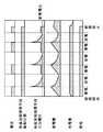
図1は本発明の実施例1の熱搬送装置の断面図、図2は本発明の実施例1の熱搬送装置の運転シーケンス図である。
【0021】
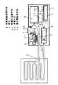
図において、1は熱搬送装置本体、2は燃焼手段、3は熱交換手段であり、燃焼手段2の熱を受熱し、その熱を熱媒と熱交換する。4は熱媒強制循環手段であり、熱媒を搬送する。6はガスボンベであり燃焼手段2のエネルギー源としてガスを供給する。7は装置の運転操作を行う操作部である。8は放熱手段であり、一端を熱媒強制循環手段4に接続し、他端を熱交換手段3に接続して熱交換手段3で熱交換した熱媒を循環させて放熱する。20は熱電気変換手段であり、燃焼手段2の熱を高温側面21に受熱し、その熱を低温側面22から熱交換手段3へ伝熱することで冷却され、高温側面21と低温側面22との温度差に応じた電力を発生する。23は蓄電手段23であり、熱電気変換手段20の発生電力を蓄電する。24は蓄放電制御手段であり、蓄電手段23の蓄電が所定値に達すると放電させ熱媒強制循環手段4を駆動するものである。
【0022】
この構成における動作,作用について説明する。燃焼手段2を燃焼させると、この燃焼手段2の燃焼熱を熱電気変換手段20は高温側面21に受熱し高温になる。さらに熱は熱交換手段3へ伝熱する。熱電気変換手段20は高温側面21と低温側面22との温度差に応じた電力を発生する。蓄電手段23は熱電気変換手段20の発生電力を蓄電する。蓄放電制御手段24はこの蓄電手段23の蓄電が所定値に達すると放電させ熱媒強制循環手段4を駆動する。そして熱媒強制循環手段4は駆動して熱媒を熱交換手段3へ搬送し、伝わった燃焼手段2の熱を熱媒と熱交換させる。さらに熱媒は放熱手段8に循環し放熱して熱媒強制循環手段4に戻り、熱搬送ができる。燃焼手段2は放電することで蓄電が徐々に減少し、やがて放電電力が熱媒強制循環手段4の駆動電力以下まで低下すると、蓄放電制御手段24は放電を停止させて再び、熱電気変換手段20の発生電力を蓄電させ、以降この動作を繰り返して運転が行われる。
【0023】
さらに、蓄電手段23が熱電気変換手段20の発生電力を蓄電し、蓄放電制御手段24がこの蓄電手段23の蓄電が所定値に達すると放電させ熱媒強制循環手段4を駆動するため、熱媒強制循環手段4の駆動電力相当の電力を常時、発電する必要がなく、熱電気変換手段20は少量、小型でよい。また、燃焼手段2の燃焼熱量が変動し、発生電力が少ない方向に変動しても熱媒強制循環手段4を駆動することができる。
【0024】
(実施例2)
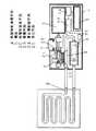
図3は本発明の実施例2の熱搬送装置の断面図である。
【0025】
実施例1と異なる点は、燃焼手段2の熱を高温側面21に受熱し、その熱を低温側面22から熱交換手段3へ伝熱することで冷却され、高温側面21と低温側面22との温度差に応じた電力を発生する熱電気変換手段20と、この熱電気変換素手段20の低温側面22から受熱し、熱媒に熱交換する熱交換手段3と、前記熱電気変換手段20の発生電力により駆動して熱媒を前記熱交換手段3へ搬送し、熱電気変換手段20を介して伝わった燃焼手段2の熱を熱媒と熱交換させる熱媒強制循環手段4を設けたところである。
【0026】
なお実施例1と同一符号のものは同一構造を有し、説明は省略する。
次に動作,作用について説明する。燃焼手段2を燃焼させると熱電気変換手段20が高温側面21に受熱し高温になる。さらに熱は熱電気変換手段20の高温側面21から低温側面22へ伝わり、熱交換手段3へ伝熱する。熱電気変換手段20の低温側面22は熱交換手段3へ伝熱することで冷却されるため、熱電気変換手段20は高温側面21と低温側面22との温度差に応じた電力を発生する。蓄電手段23は熱電気変換手段20の発生電力を蓄電する。蓄放電制御手段24はこの蓄電手段23の蓄電が所定値に達すると放電させ熱媒強制循環手段4を駆動する。そして熱媒強制循環手段4は駆動して熱媒を熱交換手段3へ搬送し、伝わった燃焼手段2の熱を熱媒と熱交換させる。さらに熱媒は放熱手段8に循環し放熱して熱媒強制循環手段4に戻り、熱搬送ができる。蓄電手段13が放電することで蓄電が徐々に減少し、やがて放電電力が熱媒強制循環手段4の駆動電力以下まで低下すると、蓄放電制御手段24は放電を停止させて再び、熱電気変換手段20の発生電力を蓄電させ、以降この動作を繰り返して運転が行われる。そして、蓄電手段23が熱電気変換手段20の発生電力を蓄電し、蓄放電制御手段24がこの蓄電手段23の蓄電が所定値に達すると放電させ熱媒強制循環手段4を駆動するため、熱媒強制循環手段4の駆動電力相当の電力を常時、発電する必要がなく、熱電気変換手段20は少量、小型でよい。また、燃焼手段2の燃焼熱量が変動し、発生電力が少ない方向に変動しても熱媒強制循環手段4を駆動することができる。さらに熱電気変換手段20は燃焼手段2の燃焼熱の大部分を高温側面21に受熱し、低温側面22から熱交換手段3へ伝熱して熱媒を加熱すると同時に発電するため、従来のようにバーナ16の熱量の大部分が直接、熱交換器12を加熱して温水に熱交換し、低い割合の熱量が熱発電素子14を加熱する構成に比べ、発生電力が小さいためポンプ13が駆動できないとか、循環流量が不足することもなく、確実に熱媒強制循環手段4を駆動できる。位置の制約から循環水路10とは別途分岐したバイパス送水路18を設けることもなく、構成が簡単になり、大きく発電するだけの熱電気変換手段20を取り付けられ、前述同様に確実に熱媒強制循環手段4を駆動できる。
【0027】
(実施例3)
図4は本発明の実施例3の熱搬送装置の断面図、図5は本発明の実施例3の熱搬送装置の運転シーケンス図である。
【0028】
実施例1と異なる点は、熱電気変換素手段20の発生電力を蓄わえ所定値に達する迄の間は電池5の電力を通電させて熱媒強制循環手段4を駆動し、熱電気変換素手段20の発生電力を蓄電し、蓄電手段23の蓄電が所定値に達すると電池5の電力の通電を停止し、蓄わえた熱電気変換素手段20の発生電力を放電させて熱媒強制循環手段4を駆動するように制御する蓄放電制御手段24を設けたところである。
【0029】
なお、実施例1と同一符号のものは同一構造を有し、説明は省略する。
次に動作,作用について説明する。燃焼手段2を燃焼させると熱電気変換手段20は高温側面21に受熱し電力を発生するが、蓄電手段23がこの発生電力を蓄電し、所定値に達する迄の間は電池5の電力を通電させて熱媒強制循環手段4を駆動させ、蓄電手段23の蓄電が所定値に達すると電池5の電力の通電を停止し、蓄わえた熱電気変換素手段20の発生電力を放電させて熱媒強制循環手段4を駆動するように蓄放電制御手段24が制御する。熱媒強制循環手段4は熱媒を熱交換手段3へ搬送し、伝わった燃焼手段2の熱を熱媒と熱交換させ、次に放熱手段8に循環して放熱させ、さらに熱媒強制循環手段4に戻り、熱搬送が行われる。蓄電手段23は放電することで蓄電が徐々に減少し、やがて放電電力が熱媒強制循環手段4の駆動電力以下まで低下すると、蓄放電制御手段24は放電を停止させて再び、熱電気変換手段20の発生電力を蓄電させ、電池5の電力を通電させて熱媒強制循環手段4を駆動する。以降この動作を繰り返して運転が行われる。そして、
蓄電手段23が発生電力を蓄電し、所定値に達する迄の間は電池5の電力を通電させて熱媒強制循環手段4を駆動させ、蓄電手段23の蓄電が所定値に達すると電池5の電力の通電力を停止し、蓄わえた熱電気変換素手段20の発生電力を放電させるため、熱媒強制循環手段4の駆動電力相当の電力を常時、発電する必要がなく、熱電気変換手段20は少量、小型でよい。また、燃焼手段2の燃焼熱量が変動し、発生電力が少ない方向に変動しても熱媒強制循環手段4を駆動することができる。そして、運転開始から即時に電池5により熱媒強制循環手段4を駆動することができ、効率よく熱搬送が行われる。従来のように電池5のみで熱媒強制循環手段4を駆動する場合に比べ、電池交換5の交換頻度と手間が減少し、電池5の費用も軽減して経済的である。運転開始から即時に電池5により熱媒強制循環手段4を駆動することができ、効率よく熱搬送が行われる。
【0030】
(実施例4)
図6は本発明の実施例4の熱搬送装置の運転シーケンス図である。
【0031】
実施例3と異なる点は、熱電気変換素手段20の発生電力が所定値に達する迄の間は電池5の電力を通電させて、熱電気変換素手段20の発生電力と電池5の電力の併用で熱媒強制循環手段4を駆動し、熱電気変換素手段20の発生電力が所定値に達すると電池5の電力の通電を停止して、熱電気変換素手段20の発生電力単独で放電させて熱媒強制循環手段4を駆動するように制御する蓄放電制御手段24を設けたところである。
【0032】
なお実施例1と同一符号のものは同一構造を有し、説明は省略する。
次に動作,作用について説明する。燃焼手段2を燃焼させると熱電気変換手段20は高温側面21に受熱し電力を発生するが、所定値に達する迄の間は熱電気変換素手段20の発生電力と電池5の電力の併用で熱媒強制循環手段4を駆動し、熱電気変換素手段20の発生電力が所定値に達すると電池5の電力の通電を停止して、熱電気変換素手段20の発生電力単独で放電させて熱媒強制循環手段4を駆動するように蓄放電制御手段24が制御する。熱媒強制循環手段4は熱媒を熱交換手段3へ搬送し、伝わった燃焼手段2の熱を熱媒と熱交換させ、次に放熱手段8に循環して放熱させ、さらに熱媒強制循環手段4に戻り、熱搬送が行われる。熱電気変換手段20の発生電力が低下して所定値以下になると、再び熱電気変換素手段20の発生電力と電池5の電力の併用で熱媒強制循環手段4を駆動するように制御される。以降この動作を繰り返して運転が行われる。そして、熱電気変換素手段20の発生電力が所定値に達する迄の間は熱電気変換素手段20の発生電力と電池5の電力の併用で熱媒強制循環手段4を駆動し、熱電気変換素手段20の発生電力が所定値に達すると、熱電気変換素手段20の発生電力単独で放電させて熱媒強制循環手段4を駆動するため、熱媒強制循環手段4の駆動電力相当の電力を常時、発電する必要がなく、熱電気変換手段20は少量、小型でよい。また、燃焼手段2の燃焼熱量が変動し、発生電力が少ない方向に変動しても熱媒強制循環手段4を駆動することができる。そして、運転開始から即時に電池5により熱媒強制循環手段4を駆動することができ、効率よく熱搬送が行われる。従来のように電池5のみで熱媒強制循環手段4を駆動する場合に比べ、電池交換5の頻度と手間が減少し、電池5の費用も軽減して経済的である。運転開始から即時に電池5により熱媒強制循環手段4を駆動することができ、効率よく熱搬送が行われる。
【0033】
(実施例5)
図7は本発明の実施例5の熱搬送装置の断面図である。
【0034】
実施例1と異なる点は、また、熱媒強制循環手段4への通電回路に昇圧手段25を設け、熱電気変換素手段20の発生電力の電圧よりも高い駆動電圧を必要とする熱媒強制循環手段4に対し、駆動電圧以上に昇圧することで駆動を可能とする蓄放電制御手段24を設けたところである。
【0035】
なお実施例1と同一符号のものは同一構造を有し、説明は省略する。
次に動作,作用について説明する。燃焼手段2を燃焼させると熱電気変換手段20は高温側面21に受熱し電力を発生するが、蓄電手段23がこの発生電力を蓄電し、所定値に達すると蓄わえた発生電力を昇圧手段25に放電させる。もしくは熱電気変換手段20の発生電力とか電池5の電力を直接に熱媒強制循環手段4に通電する。昇圧手段25はこれらの電力を昇圧し熱電気変換素手段20の発生電力の電圧もしくは電池5の電圧よりも高い駆動電圧を必要とする熱媒強制循環手段4に対し、駆動電圧以上に昇圧することで駆動を可能とする。熱媒強制循環手段4は熱媒を熱交換手段3へ搬送し、伝わった燃焼手段2の熱を熱媒と熱交換させ、次に放熱手段8に循環して放熱させ、さらに熱媒強制循環手段4に戻り、熱搬送が行われる。そして、一般的には熱電気変換手段20の発生電力は数ボルト以下であるが熱媒強制循環手段4の駆動電圧より低くても駆動できる。
【0036】
【発明の効果】
以上のように本発明によれば下記の効果が得られる。
【0037】
(1)蓄電手段が熱電気変換手段の発生電力を蓄電し、蓄放電制御手段がこの蓄電手段の蓄電が所定値に達すると放電させ熱媒強制循環手段を駆動するため、熱媒強制循環手段の駆動電力相当の電力を常時、発電する必要がなく、熱電気変換手段は少量、小型でよいという有利な効果を有する。また、燃焼手段の燃焼熱量が変動し、発生電力が少ない方向に変動しても熱媒強制循環手段を駆動することができるという有利な効果を有する。
【0038】
(2)蓄電手段が熱電気変換手段の発生電力を蓄電し、蓄放電制御手段がこの蓄電手段の蓄電が所定値に達すると放電させ熱媒強制循環手段を駆動するため、熱媒強制循環手段の駆動電力相当の電力を常時、発電する必要がなく、熱電気変換手段は少量、小型でよいという有利な効果を有する。また、燃焼手段の燃焼熱量が変動し、発生電力が少ない方向に変動しても熱媒強制循環手段を駆動することができるという有利な効果を有する。さらに熱電気変換手段は燃焼手段の燃焼熱の大部分を高温側面に受熱し、低温側面から熱交換手段へ伝熱して熱媒を加熱すると同時に発電するため、従来のようにバーナの熱量の大部分が直接、熱交換器を加熱して温水に熱交換し、低い割合の熱量が熱発電素子を加熱する構成に比べ、発生電力が小さいためポンプが駆動できないとか、循環流量が不足することもなく、確実に熱媒強制循環手段を駆動できる。位置の制約から循環水路とは別途分岐したバイパス送水路を設けることもなく、構成が簡単になり、大きく発電するだけの熱電気変換手段を取り付けられ、前述同様に確実に熱媒強制循環手段を駆動できるという有利な効果を有する。
【0039】
(3)蓄電手段が発生電力を蓄電し、所定値に達する迄の間は電池の電力を通電させて熱媒強制循環手段を駆動させ、蓄電手段の蓄電が所定値に達すると電池の電力の通電を停止し、蓄わえた熱電気変換素手段の発生電力を放電させるため、熱媒強制循環手段の駆動電力相当の電力を常時、発電する必要がなく、熱電気変換手段は少量、小型でよいという有利な効果を有する。また、燃焼手段の燃焼熱量が変動し、発生電力が少ない方向に変動しても熱媒強制循環手段を駆動することができるという有利な効果を有する。そして、運転開始から即時に電池により熱媒強制循環手段を駆動することができ、効率よく熱搬送が行われるという有利な効果を有する。従来のように電池のみで熱媒強制循環手段を駆動する場合に比べ、電池交換の頻度と手間が減少し、電池の費用も軽減して経済的である。運転開始から即時に電池により熱媒強制循環手段を駆動することができ、効率よく熱搬送が行われるという有利な効果を有する。
【0040】
(4)熱電気変換素手段の発生電力が所定値に達する迄の間は熱電気変換素手段の発生電力と電池の電力の併用で熱媒強制循環手段を駆動し、熱電気変換素手段の発生電力が所定値に達すると、熱電気変換素手段の発生電力単独で放電させて熱媒強制循環手段を駆動するため、熱媒強制循環手段の駆動電力相当の電力を常時、発電する必要がなく、熱電気変換手段は少量、小型でよいという有利な効果を有する。また、燃焼手段の燃焼熱量が変動し、発生電力が少ない方向に変動しても熱媒強制循環手段を駆動することができるという有利な効果を有する。そして、運転開始から即時に電池により熱媒強制循環手段を駆動することができ、効率よく熱搬送が行われるという有利な効果を有する。従来のように電池のみで熱媒強制循環手段を駆動する場合に比べ、電池交換の頻度と手間が減少し、電池の費用も軽減して経済的であるという有利な効果を有する。運転開始から即時に電池により熱媒強制循環手段を駆動することができ、効率よく熱搬送が行われるという有利な効果を有する。
【0041】
(5)熱媒強制循環手段への通電回路に昇圧手段を設け、熱電気変換素手段の発生電力の電圧よりも高い駆動電圧を必要とする熱媒強制循環手段に対し、駆動電圧以上に昇圧することで駆動を可能とする。そして、一般的には熱電気変換手段の発生電力は数ボルト以下であるが熱媒強制循環手段の駆動電圧より低くても駆動できるという有利な効果を有する。
【図面の簡単な説明】
【図1】本発明の実施例1の熱搬送装置の断面図
【図2】本発明の実施例1の熱搬送装置の運転シーケンス図
【図3】本発明の実施例2の熱搬送装置の断面図
【図4】本発明の実施例3の熱搬送装置の断面図
【図5】本発明の実施例3の熱搬送装置の運転シーケンス図
【図6】本発明の実施例4の熱搬送装置の運転シーケンス図
【図7】本発明の実施例5の熱搬送装置の断面図
【図8】従来の熱搬送装置の断面図
【符号の説明】
1 熱搬送装置本体
2 燃焼手段
3 熱交換手段
4 熱媒強制循環手段
5 電池
7 操作部
8 放熱手段
20 熱電気変換手段
21 高温側面
22 低温側面
23 蓄電手段
24 蓄放電制御手段
25 昇圧手段[0001]
BACKGROUND OF THE INVENTION
The present invention relates to a heat transfer device for combustion heat that is portable and has a warming function.
[0002]
[Prior art]
Conventionally, as shown in FIG. 8, this type of heat transfer device is connected to the
[0003]
In the above configuration, when the hot water of the bathtub main body 9 is spouted, when the
[0004]
[Problems to be solved by the invention]
However, in the conventional apparatus as described above, the
[0005]
[Means for Solving the Problems]
In order to solve the above problems, the present invention provides a combustion means, a thermoelectric conversion element means that receives heat from the combustion means on a high temperature side surface to generate a thermoelectromotive force, and heat that receives heat from the combustion means and exchanges heat. An exchange means, a heat medium driven by electric power to convey the heat medium to the heat exchange means, heat exchange forced circulation means to exchange heat, one end connected to the heat medium forced circulation means, and the other end connected to the heat exchange means Heat dissipation means that circulates and dissipates heat through the heat medium exchanged by the heat exchange means, power storage means that stores the generated power of the thermoelectric conversion means, and discharges the heat medium forcibly circulating when the power storage of the power storage means reaches a predetermined value And storage / discharge control means for driving the means.
[0006]
According to the above invention, when the combustion means burns, the thermoelectric conversion means receives the combustion heat of the combustion means on the high temperature side surface and becomes high temperature. Furthermore, heat is transferred to the heat exchange means. The thermoelectric conversion means generates electric power according to the temperature difference between the high temperature side surface and the low temperature side surface. The power storage means stores the electric power generated by the thermoelectric conversion means. The storage / discharge control means discharges when the power stored in the power storage means reaches a predetermined value, and drives the heat medium forced circulation means. The heat medium forced circulation means is driven to convey the heat medium to the heat exchange means, and exchanges the heat of the transmitted combustion means with the heat medium. Further, the heat medium circulates to the heat radiating means, radiates heat, returns to the heat medium forced circulation means, and can carry heat. When the combustion means discharges, the stored electricity gradually decreases, and when the discharge power eventually falls below the drive power of the heat medium forced circulation means, the storage / discharge control means stops the discharge and again generates power generated by the thermoelectric conversion means. Is stored, and this operation is repeated thereafter for operation.
[0007]
Further, the power storage means stores the electric power generated by the thermoelectric conversion means, and the storage / discharge control means discharges and drives the heat medium forced circulation means when the power storage of the power storage means reaches a predetermined value. There is no need to constantly generate power equivalent to drive power, and the thermoelectric conversion means may be small and small. Further, the heat medium forced circulation means can be driven even if the combustion heat quantity of the combustion means fluctuates and the generated power fluctuates in a direction that decreases.
[0008]
DETAILED DESCRIPTION OF THE INVENTION
The present invention relates to a combustion means, a thermoelectric conversion element means for generating heat electromotive force by receiving heat of the combustion means on a high temperature side surface, a heat exchange means for receiving heat from the combustion means and exchanging heat, and driving with electric power. A heat medium forced circulation means for conveying the heat medium to the heat exchange means and exchanging heat; one end connected to the heat medium forced circulation means; the other end connected to the heat exchange means and the heat exchange means Heat radiating means for circulating and dissipating the heat medium exchanged in the heat, power storage means for storing the electric power generated by the thermoelectric conversion means, and discharging when the power stored in the power storage means reaches a predetermined value, forcing the heat medium to circulate And storage / discharge control means for driving.
[0009]
When the combustion means is combusted, the thermoelectric conversion means receives the combustion heat of the combustion means on the high temperature side surface and becomes high temperature. Furthermore, heat is transferred to the heat exchange means. The thermoelectric conversion means generates electric power according to the temperature difference between the high temperature side surface and the low temperature side surface. The power storage means stores the electric power generated by the thermoelectric conversion means. The storage / discharge control means discharges when the power stored in the power storage means reaches a predetermined value, and drives the heat medium forced circulation means.
[0010]
The power storage means stores the electric power generated by the thermoelectric conversion means, and the storage / discharge control means discharges when the power storage of the power storage means reaches a predetermined value and drives the heat medium forced circulation means. There is no need to constantly generate electric power equivalent to electric power, and the thermoelectric conversion means may be small and small. Further, the heat medium forced circulation means can be driven even if the combustion heat quantity of the combustion means fluctuates and the generated power fluctuates in a direction that decreases.
[0011]
In addition, the combustion means and the heat of the combustion means are received by the high temperature side surface, and the heat is transferred from the low temperature side surface to the heat exchange means to be cooled, and electric power corresponding to the temperature difference between the high temperature side surface and the low temperature side surface is generated. The generated thermoelectric conversion means, the heat exchange means that receives heat from the low temperature side surface of the thermoelectric conversion element means, and exchanges heat with the heat medium, and is driven by the generated electric power of the thermoelectric conversion means to exchange the heat medium with the heat medium. A heat medium forced circulation means for exchanging heat of the combustion means conveyed to the means through the thermoelectric conversion means with the heat medium, one end connected to the heat medium forced circulation means, and the other end to the heat exchange A heat dissipating means for circulating and dissipating heat from the heat exchange medium connected to the heat exchanging means, an accumulating means for accumulating electric power generated by the thermoelectric conversion element means, and the accumulating power of the accumulating means reaches a predetermined value A storage / discharge system that discharges when it reaches and drives the heat medium forced circulation means And has a means.
[0012]
And if a combustion means is burned, a thermoelectric conversion means will receive heat at a high temperature side surface, and will become high temperature. Furthermore, heat is transferred from the high temperature side surface to the low temperature side surface of the thermoelectric conversion means, and is transferred to the heat exchange means. Since the low temperature side surface of the thermoelectric conversion means is cooled by transferring heat to the heat exchange means, the thermoelectric conversion means generates electric power according to the temperature difference between the high temperature side surface and the low temperature side surface. The power storage means stores the electric power generated by the thermoelectric conversion means. The storage / discharge control means discharges when the power stored in the power storage means reaches a predetermined value, and drives the heat medium forced circulation means. The heat medium forced circulation means is driven to convey the heat medium to the heat exchange means, and exchanges the heat of the transmitted combustion means with the heat medium. Further, the heat medium circulates to the heat radiating means, radiates heat, returns to the heat medium forced circulation means, and can carry heat. When the combustion means discharges, the stored electricity gradually decreases, and when the discharge power eventually falls below the drive power of the heat medium forced circulation means, the storage / discharge control means stops the discharge and again generates power generated by the thermoelectric conversion means. Is stored, and this operation is repeated thereafter for operation. Then, the power storage means stores the electric power generated by the thermoelectric conversion means, and the storage / discharge control means discharges when the power storage of the power storage means reaches a predetermined value and drives the heat medium forced circulation means. There is no need to constantly generate power equivalent to drive power, and the thermoelectric conversion means may be small and small. Further, the heat medium forced circulation means can be driven even if the combustion heat quantity of the combustion means fluctuates and the generated power fluctuates in a direction that decreases. Furthermore, since the thermoelectric conversion means receives most of the combustion heat of the combustion means on the high temperature side, transfers heat from the low temperature side to the heat exchange means and heats the heating medium at the same time as generating electricity, the amount of heat of the burner is large as before. The part directly heats the heat exchanger and exchanges heat with hot water. Compared with the configuration in which a low proportion of heat heats the thermoelectric generator, the generated power is small and the pump cannot be driven, or the circulation flow rate may be insufficient. And the heat medium forced circulation means can be driven reliably. Due to location restrictions, there is no need to provide a bypass waterway that is branched separately from the circulation waterway, the configuration is simplified, and thermoelectric conversion means that can generate large amounts of electricity can be installed. Can drive.
[0013]
In addition, the electric power of the battery is energized to drive the heating medium forced circulation means until the electric power generated by the thermoelectric conversion means reaches a predetermined value, and the electric power generated by the thermoelectric conversion means is stored, Storage / discharge control means for controlling energization of the battery power to stop when the power stored in the power storage means reaches a predetermined value, and discharging the generated electric power of the thermoelectric conversion element means to drive the heat medium forced circulation means It is what has.
[0014]
When the combustion means is combusted, the thermoelectric conversion means receives heat on the high temperature side surface and generates electric power, but the electric storage means stores this generated electric power and energizes the battery power until it reaches a predetermined value. The medium forced circulation means is driven, and when the electricity stored in the power storage means reaches a predetermined value, the energization of the battery is stopped, and the generated electric power of the thermoelectric conversion element means is discharged to drive the heat medium forced circulation means. Thus, the storage / discharge control means controls. The heat medium forced circulation means conveys the heat medium to the heat exchange means, exchanges heat of the transmitted combustion means with the heat medium, then circulates to the heat dissipation means to radiate heat, and returns to the heat medium forced circulation means, Heat transfer is performed. When the power storage means is discharged, the power storage gradually decreases, and when the discharge power eventually drops below the drive power of the heat medium forced circulation means, the storage / discharge control means stops the discharge and again generates power generated by the thermoelectric conversion means. Is stored, and the electric power of the battery is energized to drive the heat medium forced circulation means. Thereafter, the operation is repeated by repeating this operation. The power storage means stores the generated power and energizes the battery until the predetermined value is reached to drive the heat medium forced circulation means. When the power storage means reaches the predetermined value, the battery power is supplied. And the stored electric power generated by the thermoelectric conversion element means is discharged. Therefore, it is not always necessary to generate electric power equivalent to the driving power of the heat medium forced circulation means, and the thermoelectric conversion means may be small and small in size. . Further, the heat medium forced circulation means can be driven even if the combustion heat quantity of the combustion means fluctuates and the generated power fluctuates in a direction that decreases. And a heat medium forced circulation means can be driven with a battery immediately from the start of operation, and heat transfer is performed efficiently.
[0015]
Further, the electric power of the battery is energized until the generated electric power of the thermoelectric conversion element means reaches a predetermined value, and the heat medium forced circulation means is driven by the combined use of the generated electric power of the thermoelectric conversion element means and the electric power of the battery. When the generated electric power of the thermoelectric converter means reaches a predetermined value, the energization of the battery is stopped, and the generated electric power of the thermoelectric converter means is discharged alone to drive the heat medium forced circulation means. It has a storage / discharge control means.
[0016]
When the combustion means is combusted, the thermoelectric conversion means receives the heat on the high temperature side surface and generates electric power. However, until the predetermined value is reached, the heat medium is forced by using both the electric power generated by the thermoelectric conversion element means and the electric power of the battery. When the circulating means is driven and the electric power generated by the thermoelectric conversion element reaches a predetermined value, the energization of the battery is stopped, and the electric power generated by the thermoelectric conversion element alone is discharged to drive the heating medium forced circulation means. Thus, the storage / discharge control means controls. The heat medium forced circulation means conveys the heat medium to the heat exchange means, exchanges heat of the transmitted combustion means with the heat medium, then circulates to the heat dissipation means to radiate heat, and returns to the heat medium forced circulation means, Heat transfer is performed. When the electric power generated by the thermoelectric conversion means decreases to a predetermined value or less, the heat medium forced circulation means is again driven by using the electric power generated by the thermoelectric conversion element means and the battery power again. Thereafter, the operation is repeated by repeating this operation. And
Until the generated power of the thermoelectric converter means reaches a predetermined value, the heat medium forced circulation means is driven by the combined use of the generated power of the thermoelectric converter means and the power of the battery, and the generated power of the thermoelectric converter means is reduced. When the predetermined value is reached, the electric power generated by the thermoelectric conversion element means is discharged alone to drive the heat medium forced circulation means, so there is no need to constantly generate electric power equivalent to the drive power of the heat medium forced circulation means. The electrical conversion means may be small and small. Further, the heat medium forced circulation means can be driven even if the combustion amount of the combustion means fluctuates and the generated power fluctuates in a direction that decreases. And a heat medium forced circulation means can be driven with a battery immediately from the start of operation, and heat transfer is performed efficiently.
[0017]
Further, a boosting means is provided in the energization circuit to the heat medium forced circulation means, and the heat medium forced circulation means that requires a drive voltage higher than the voltage of the electric power generated by the thermoelectric converter means is boosted to the drive voltage or higher. Thus, a storage / discharge control means that can be driven is provided.
[0018]
When the combustion means is combusted, the thermoelectric conversion means receives heat on the high temperature side surface and generates electric power. The electric storage means stores this generated electric power, and when the predetermined value is reached, the stored generated electric power is discharged to the boosting means. . Alternatively, the boosting means is directly energized with the electric power generated by the thermoelectric conversion means or the electric power of the battery. The boosting means boosts these powers to boost the heating medium forced circulation means that requires a driving power higher than the voltage of the electric power generated by the thermoelectric converter means or the voltage of the battery by driving it above the driving voltage. Make it possible. The heat medium forced circulation means conveys the heat medium to the heat exchange means, exchanges heat of the transmitted combustion means with the heat medium, then circulates to the heat dissipation means to radiate heat, and returns to the heat medium forced circulation means, Heat transfer is performed. In general, the generated voltage of the thermoelectric conversion means is several volts or less, but it can be driven even if it is lower than the drive voltage of the heat medium forced circulation means.
[0019]
【Example】
Embodiments of the present invention will be described below with reference to the drawings.
[0020]
Example 1
1 is a cross-sectional view of a heat transfer device according to a first embodiment of the present invention, and FIG. 2 is an operation sequence diagram of the heat transfer device according to the first embodiment of the present invention.
[0021]
In the figure, 1 is a heat transfer device body, 2 is a combustion means, and 3 is a heat exchange means, which receives the heat of the combustion means 2 and exchanges the heat with a heat medium. 4 is a heat medium forced circulation means, and conveys the heat medium. A
[0022]
The operation and action in this configuration will be described. When the combustion means 2 is burned, the thermoelectric conversion means 20 receives the combustion heat of the combustion means 2 on the high
[0023]
Further, the power storage means 23 stores the generated electric power of the thermoelectric conversion means 20, and the storage / discharge control means 24 discharges when the power storage of the power storage means 23 reaches a predetermined value, and drives the heat medium forced circulation means 4. There is no need to constantly generate power corresponding to the drive power of the medium forced circulation means 4, and the thermoelectric conversion means 20 may be small and small. Further, the heat medium forced circulation means 4 can be driven even if the combustion heat quantity of the combustion means 2 fluctuates and fluctuates in a direction where the generated power is small.
[0024]
(Example 2)
FIG. 3 is a cross-sectional view of the heat transfer device according to the second embodiment of the present invention.
[0025]
The difference from Example 1 is that the heat of the combustion means 2 is received by the high
[0026]
In addition, the thing of the same code | symbol as Example 1 has the same structure, and abbreviate | omits description.
Next, the operation and action will be described. When the combustion means 2 is burned, the thermoelectric conversion means 20 receives heat at the high
[0027]
(Example 3)
FIG. 4 is a sectional view of the heat transfer device according to the third embodiment of the present invention, and FIG. 5 is an operation sequence diagram of the heat transfer device according to the third embodiment of the present invention.
[0028]
The difference from the first embodiment is that the electric power of the
[0029]
In addition, the thing of the same code | symbol as Example 1 has the same structure, and abbreviate | omits description.
Next, the operation and action will be described. When the combustion means 2 is combusted, the thermoelectric conversion means 20 receives heat at the high
The power storage means 23 stores the generated power, and the power of the
[0030]
(Example 4)
FIG. 6 is an operation sequence diagram of the heat transfer device according to the fourth embodiment of the present invention.
[0031]
The difference from the third embodiment is that the power of the
[0032]
In addition, the thing of the same code | symbol as Example 1 has the same structure, and abbreviate | omits description.
Next, the operation and action will be described. When the combustion means 2 is combusted, the thermoelectric conversion means 20 receives heat at the high
[0033]
(Example 5)
FIG. 7 is a cross-sectional view of the heat transfer device according to the fifth embodiment of the present invention.
[0034]
The difference from the first embodiment is that a booster means 25 is provided in the energization circuit to the heat medium forced circulation means 4, and a heat medium force that requires a drive voltage higher than the voltage of the electric power generated by the thermoelectric conversion element means 20 is required. The circulation means 4 is provided with a storage / discharge control means 24 that can be driven by boosting it to a driving voltage or higher.
[0035]
In addition, the thing of the same code | symbol as Example 1 has the same structure, and abbreviate | omits description.
Next, the operation and action will be described. When the combustion means 2 is combusted, the thermoelectric conversion means 20 receives heat at the high
[0036]
【The invention's effect】
As described above, according to the present invention, the following effects can be obtained.
[0037]
(1) The power storage means stores the electric power generated by the thermoelectric conversion means, and the storage / discharge control means discharges when the power storage of the power storage means reaches a predetermined value to drive the heat medium forced circulation means. Therefore, it is not necessary to always generate electric power equivalent to the driving electric power, and the thermoelectric conversion means has an advantageous effect of being small and small in size. In addition, there is an advantageous effect that the heat medium forced circulation means can be driven even if the amount of combustion heat of the combustion means fluctuates and the generated power fluctuates in a direction that decreases.
[0038]
(2) Since the power storage means stores the generated electric power of the thermoelectric conversion means, and the storage / discharge control means discharges when the power storage of the power storage means reaches a predetermined value and drives the heat medium forced circulation means, the heat medium forced circulation means Therefore, it is not necessary to always generate electric power equivalent to the driving electric power, and the thermoelectric conversion means has an advantageous effect of being small and small in size. In addition, there is an advantageous effect that the heat medium forced circulation means can be driven even if the amount of combustion heat of the combustion means fluctuates and the generated power fluctuates in a direction that decreases. Furthermore, since the thermoelectric conversion means receives most of the combustion heat of the combustion means on the high temperature side, transfers heat from the low temperature side to the heat exchange means and heats the heating medium at the same time as generating electricity, the amount of heat of the burner is large as before. The part directly heats the heat exchanger and exchanges heat with hot water. Compared with the configuration in which a low proportion of heat heats the thermoelectric generator, the generated power is small and the pump cannot be driven, or the circulation flow rate may be insufficient. And the heat medium forced circulation means can be driven reliably. Due to location restrictions, there is no need to provide a bypass waterway that is branched separately from the circulation waterway, the configuration is simplified, and thermoelectric conversion means that can generate large amounts of electricity can be installed. It has the advantageous effect that it can be driven.
[0039]
(3) The power storage means stores the generated power, and the battery power is energized to drive the heat medium forced circulation means until the power reaches the predetermined value, and when the power storage means reaches the predetermined value, In order to stop energization and discharge the generated electric power of the thermoelectric conversion element means, it is not necessary to constantly generate power equivalent to the drive power of the heat medium forced circulation means, and the thermoelectric conversion means is small and small in size. It has the advantageous effect of being good. In addition, there is an advantageous effect that the heat medium forced circulation means can be driven even if the amount of combustion heat of the combustion means fluctuates and the generated power fluctuates in a direction that decreases. The heat medium forced circulation means can be driven by the battery immediately after the operation is started, and there is an advantageous effect that heat transfer is performed efficiently. Compared to the conventional case where the heat medium forced circulation means is driven only by a battery, the frequency and labor of battery replacement are reduced, and the cost of the battery is reduced, which is economical. The heat medium forced circulation means can be driven by the battery immediately after the start of operation, and there is an advantageous effect that heat transfer is performed efficiently.
[0040]
(4) Until the generated power of the thermoelectric converter means reaches a predetermined value, the heat medium forced circulation means is driven by the combined use of the generated power of the thermoelectric converter means and the power of the battery, When the generated power reaches a predetermined value, the heat medium forced circulation means is driven by discharging only the generated power of the thermoelectric conversion means means, so it is necessary to always generate power equivalent to the drive power of the heat medium forced circulation means. In addition, the thermoelectric conversion means has the advantageous effect of being small and small in size. In addition, there is an advantageous effect that the heat medium forced circulation means can be driven even if the amount of combustion heat of the combustion means fluctuates and the generated power fluctuates in a direction that decreases. The heat medium forced circulation means can be driven by the battery immediately after the operation is started, and there is an advantageous effect that heat transfer is performed efficiently. Compared to the case where the heat medium forced circulation means is driven only by a battery as in the prior art, there are advantageous effects that the frequency and labor of battery replacement are reduced, the cost of the battery is reduced, and it is economical. The heat medium forced circulation means can be driven by the battery immediately after the start of operation, and there is an advantageous effect that heat transfer is performed efficiently.
[0041]
(5) A boosting means is provided in the energization circuit to the heat medium forced circulation means, and the heat medium forced circulation means that requires a drive voltage higher than the voltage of the electric power generated by the thermoelectric converter means is boosted to a voltage higher than the drive voltage. This enables driving. In general, the electric power generated by the thermoelectric conversion means is several volts or less, but it has an advantageous effect that it can be driven even if it is lower than the drive voltage of the heat medium forced circulation means.
[Brief description of the drawings]
FIG. 1 is a cross-sectional view of a heat transfer device according to a first embodiment of the present invention.
FIG. 2 is an operation sequence diagram of the heat transfer device according to the first embodiment of the present invention.
FIG. 3 is a sectional view of a heat transfer device according to a second embodiment of the present invention.
FIG. 4 is a sectional view of a heat transfer device according to a third embodiment of the present invention.
FIG. 5 is an operation sequence diagram of the heat transfer device according to the third embodiment of the present invention.
FIG. 6 is an operation sequence diagram of the heat transfer device according to the fourth embodiment of the present invention.
FIG. 7 is a cross-sectional view of a heat transfer device according to a fifth embodiment of the present invention.
FIG. 8 is a cross-sectional view of a conventional heat transfer device
[Explanation of symbols]
1 Heat transfer device
2 Combustion means
3 Heat exchange means
4 Heat medium forced circulation means
5 batteries
7 Operation part
8 Heat dissipation means
20 Thermoelectric conversion means
21 High temperature side
22 Low temperature side
23 Power storage means
24 Storage / discharge control means
25 Boosting means
Claims (2)
Translated fromJapanesePriority Applications (1)
| Application Number | Priority Date | Filing Date | Title |
|---|---|---|---|
| JP00831098AJP3997582B2 (en) | 1998-01-20 | 1998-01-20 | Heat transfer device |
Applications Claiming Priority (1)
| Application Number | Priority Date | Filing Date | Title |
|---|---|---|---|
| JP00831098AJP3997582B2 (en) | 1998-01-20 | 1998-01-20 | Heat transfer device |
Publications (2)
| Publication Number | Publication Date |
|---|---|
| JPH11201475A JPH11201475A (en) | 1999-07-30 |
| JP3997582B2true JP3997582B2 (en) | 2007-10-24 |
Family
ID=11689590
Family Applications (1)
| Application Number | Title | Priority Date | Filing Date |
|---|---|---|---|
| JP00831098AExpired - Fee RelatedJP3997582B2 (en) | 1998-01-20 | 1998-01-20 | Heat transfer device |
Country Status (1)
| Country | Link |
|---|---|
| JP (1) | JP3997582B2 (en) |
Cited By (1)
| Publication number | Priority date | Publication date | Assignee | Title |
|---|---|---|---|---|
| US20220252462A1 (en)* | 2019-06-28 | 2022-08-11 | Kelk Ltd. | State estimation system |
Families Citing this family (11)
| Publication number | Priority date | Publication date | Assignee | Title |
|---|---|---|---|---|
| EP2282357B1 (en) | 2005-06-28 | 2015-12-02 | Gentherm Incorporated | Thermoelectric power generator for variable thermal power source |
| CN104990301B (en) | 2007-05-25 | 2019-04-16 | 詹思姆公司 | Distribution formula thermoelectricity heating and cooling system and method |
| CN102105757A (en) | 2008-06-03 | 2011-06-22 | Bsst有限责任公司 | Thermoelectric heat pump |
| EP3151293A1 (en) | 2009-07-24 | 2017-04-05 | Gentherm Incorporated | Thermoelectric-based power generation systems and methods |
| US9293680B2 (en) | 2011-06-06 | 2016-03-22 | Gentherm Incorporated | Cartridge-based thermoelectric systems |
| US9006557B2 (en) | 2011-06-06 | 2015-04-14 | Gentherm Incorporated | Systems and methods for reducing current and increasing voltage in thermoelectric systems |
| US9306143B2 (en) | 2012-08-01 | 2016-04-05 | Gentherm Incorporated | High efficiency thermoelectric generation |
| US10270141B2 (en) | 2013-01-30 | 2019-04-23 | Gentherm Incorporated | Thermoelectric-based thermal management system |
| RU2610819C1 (en)* | 2015-12-28 | 2017-02-15 | Елена Анатольевна Ленкова | Systems of independent electric supply for units of thermal power plant |
| US11223004B2 (en) | 2018-07-30 | 2022-01-11 | Gentherm Incorporated | Thermoelectric device having a polymeric coating |
| US11152557B2 (en) | 2019-02-20 | 2021-10-19 | Gentherm Incorporated | Thermoelectric module with integrated printed circuit board |
- 1998
- 1998-01-20JPJP00831098Apatent/JP3997582B2/ennot_activeExpired - Fee Related
Cited By (2)
| Publication number | Priority date | Publication date | Assignee | Title |
|---|---|---|---|---|
| US20220252462A1 (en)* | 2019-06-28 | 2022-08-11 | Kelk Ltd. | State estimation system |
| US12253422B2 (en)* | 2019-06-28 | 2025-03-18 | Kelk Ltd. | State estimation system |
Also Published As
| Publication number | Publication date |
|---|---|
| JPH11201475A (en) | 1999-07-30 |
Similar Documents
| Publication | Publication Date | Title |
|---|---|---|
| JP3997582B2 (en) | Heat transfer device | |
| CN100424339C (en) | Thermoelectric Energy Generation System | |
| JP2006177265A (en) | Thermoelectric generator | |
| CN102418623A (en) | Rankine cycle system | |
| US8132422B2 (en) | Cogeneration system | |
| US20200251644A1 (en) | Thermoelectric generator comprising liquid metal heat exchange unit | |
| JP6040347B2 (en) | Hot air generating device and hot air generating method | |
| JP4396351B2 (en) | Thermoelectric generator | |
| JP4128054B2 (en) | Fuel cell system and operating method thereof | |
| JP3025595B2 (en) | Hot water heater | |
| CN217214789U (en) | Heat circulation system of fuel cell | |
| CN104870781B (en) | Pre-heating system for power station | |
| JP2009150612A (en) | Heat pump water heater | |
| JP3182681B2 (en) | Peltier element water heater | |
| KR20000056028A (en) | Self generator using thermoelectric semiconductor and its controlling method in electric-automobile | |
| JP2005016787A (en) | Cogeneration system | |
| JPH11201477A (en) | Heat transfer device | |
| KR100629352B1 (en) | Cogeneration System | |
| JP2007064548A (en) | Heat-storage and hot-water-storage type water heater | |
| JP2008215711A (en) | Heat source machine | |
| JPH11201546A (en) | Heat transfer device | |
| JPS6298127A (en) | Heating apparatus | |
| KR102018817B1 (en) | Intergrated heated heating system for interior heating | |
| JP2011179788A (en) | Heat supply system | |
| KR102018272B1 (en) | Intergrated heated heating system for interior heating |
Legal Events
| Date | Code | Title | Description |
|---|---|---|---|
| A621 | Written request for application examination | Free format text:JAPANESE INTERMEDIATE CODE: A621 Effective date:20040415 | |
| RD01 | Notification of change of attorney | Free format text:JAPANESE INTERMEDIATE CODE: A7421 Effective date:20040512 | |
| RD01 | Notification of change of attorney | Free format text:JAPANESE INTERMEDIATE CODE: A7421 Effective date:20050627 | |
| A977 | Report on retrieval | Free format text:JAPANESE INTERMEDIATE CODE: A971007 Effective date:20060616 | |
| A131 | Notification of reasons for refusal | Free format text:JAPANESE INTERMEDIATE CODE: A131 Effective date:20060711 | |
| A521 | Request for written amendment filed | Free format text:JAPANESE INTERMEDIATE CODE: A523 Effective date:20060907 | |
| A131 | Notification of reasons for refusal | Free format text:JAPANESE INTERMEDIATE CODE: A131 Effective date:20070206 | |
| A521 | Request for written amendment filed | Free format text:JAPANESE INTERMEDIATE CODE: A523 Effective date:20070323 | |
| TRDD | Decision of grant or rejection written | ||
| A01 | Written decision to grant a patent or to grant a registration (utility model) | Free format text:JAPANESE INTERMEDIATE CODE: A01 Effective date:20070717 | |
| A61 | First payment of annual fees (during grant procedure) | Free format text:JAPANESE INTERMEDIATE CODE: A61 Effective date:20070730 | |
| FPAY | Renewal fee payment (event date is renewal date of database) | Free format text:PAYMENT UNTIL: 20100817 Year of fee payment:3 | |
| LAPS | Cancellation because of no payment of annual fees |