JP3996171B2 - Battery pack lid providing non-contact charging interface and mobile phone including the battery pack lid - Google Patents
Battery pack lid providing non-contact charging interface and mobile phone including the battery pack lidDownload PDFInfo
- Publication number
- JP3996171B2 JP3996171B2JP2005131612AJP2005131612AJP3996171B2JP 3996171 B2JP3996171 B2JP 3996171B2JP 2005131612 AJP2005131612 AJP 2005131612AJP 2005131612 AJP2005131612 AJP 2005131612AJP 3996171 B2JP3996171 B2JP 3996171B2
- Authority
- JP
- Japan
- Prior art keywords
- battery pack
- mobile phone
- power
- pack lid
- lid
- Prior art date
- Legal status (The legal status is an assumption and is not a legal conclusion. Google has not performed a legal analysis and makes no representation as to the accuracy of the status listed.)
- Expired - Fee Related
Links
Images


Classifications
- Y—GENERAL TAGGING OF NEW TECHNOLOGICAL DEVELOPMENTS; GENERAL TAGGING OF CROSS-SECTIONAL TECHNOLOGIES SPANNING OVER SEVERAL SECTIONS OF THE IPC; TECHNICAL SUBJECTS COVERED BY FORMER USPC CROSS-REFERENCE ART COLLECTIONS [XRACs] AND DIGESTS
- Y02—TECHNOLOGIES OR APPLICATIONS FOR MITIGATION OR ADAPTATION AGAINST CLIMATE CHANGE
- Y02E—REDUCTION OF GREENHOUSE GAS [GHG] EMISSIONS, RELATED TO ENERGY GENERATION, TRANSMISSION OR DISTRIBUTION
- Y02E60/00—Enabling technologies; Technologies with a potential or indirect contribution to GHG emissions mitigation
- Y02E60/10—Energy storage using batteries
Landscapes
- Charge And Discharge Circuits For Batteries Or The Like (AREA)
- Secondary Cells (AREA)
- Battery Mounting, Suspending (AREA)
Description
Translated fromJapanese本発明は、携帯電話の非接触充電を実現するインタフェースを備えた電池パック蓋に関するものである。 The present invention relates to a battery pack lid provided with an interface for realizing non-contact charging of a mobile phone.
従来、携帯電話等の機器の電源として使用される2次電池を充電する充電器と当該2次電池との間に存在する電気的接点等に起因する問題(例えば、接点を有していることから接点が汚損した場合には、接触不良となって充電ができなくなるという問題)を解決して、充電器と接点なしで充電可能な非接触充電方式に基づく携帯電子機器用電源システムが提案されている(例えば、特許文献1参照)。 Conventionally, problems caused by an electrical contact or the like existing between a charger for charging a secondary battery used as a power source of a device such as a mobile phone and the secondary battery (for example, having a contact) In case of contact damage, the power supply system for portable electronic devices based on the non-contact charging method that can be charged without contact with the charger has been proposed. (For example, refer to Patent Document 1).
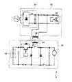
図5は、上記非接触充電方式に基づく携帯電子機器用電源システムの回路図であり、携帯電子機器用電源システム9は、携帯電子機器本体91と充電器92とを備えている。 FIG. 5 is a circuit diagram of a power supply system for portable electronic devices based on the non-contact charging method, and the power supply system 9 for portable electronic devices includes a portable electronic device
携帯電子機器本体91は降圧チョッパ93と2次電池94とを有し、充電器92は整流回路95と、励磁コイル96と、スイッチング素子98とを有する。また、降圧チョッパ93はチョークコイル97を有する。 The portable electronic device
そして、充電器92は、整流回路95から出力される直流電力をスイッチング素子98でスイッチングして励磁コイル96から電磁エネルギを放出する。充電時、チョークコイル97は励磁コイル96と電磁的に結合しているので、チョークコイル97に交流電力が誘起され、この交流電力を整流した直流電力により2次電池94が充電される。 The
前述の携帯電子機器用電源システムでは、2次電池としてニッケルカドミウム電池を使用しているが、近年では2次電池としてニッケルカドミウム電池に比較して小型軽量かつ蓄電容量が大きいリチウムイオン電池が主に使用されている。
しかしながら、従来の非接触充電方式に基づく携帯電子機器用電源システムは、前述の特許文献1記載の発明も含め、主として携帯電子機器本体と充電器とがワンセットとして取り扱われるものであった。すなわち、1台の携帯電子機器を所有するユーザは、当該電子機器用の充電器を1台所有する状況にあり、例えば、長期外出の際にこの携帯電子機器本体を携行する場合には対応する充電器をも携行する必要があり、ユーザへの負担が大きいという第1の課題があった。 However, in the conventional power supply system for portable electronic devices based on the non-contact charging method, including the invention described in
さらに、近年必須の携帯電子機器となっている携帯電話機においては、充電方式の主流が充電用コード端子付の接触充電方式という状況であった。したがって、従来の携帯電話機に上記非接触充電方式に基づく電源システムを適用しようとすると、従来の携帯電話機には適当な充電インタフェースが備わっていないために、非接触充電方式への移行が困難であるという第2の課題があった。 Furthermore, in mobile phones that have become indispensable portable electronic devices in recent years, the mainstream charging method is a contact charging method with a charging cord terminal. Therefore, when applying a power supply system based on the above contactless charging method to a conventional mobile phone, it is difficult to shift to the contactless charging method because the conventional mobile phone does not have an appropriate charging interface. There was a second problem.
あるいは、例えば、1台の携帯機器において、高速充電が可能な従来の接触充電方式と携行性に優れた非接触充電方式との併用を考えたときに、より利便性の高い充電インタフェースの必要性が第3の課題ともなり得た。 Or, for example, the need for a more convenient charging interface when considering the combined use of a conventional contact charging method capable of high-speed charging and a non-contact charging method with excellent portability in one portable device Could be the third issue.
したがって、本発明は、主としてこれらの課題を解決するためになされたものであって、携行性に優れ、かつ、接触充電方式から非接触充電方式への移行あるいは両方式の併用を容易に実現可能な非接触充電インタフェースを提供することを目的とする。 Therefore, the present invention has been made mainly for solving these problems, is excellent in portability, and can easily realize the transition from the contact charging method to the non-contact charging method or the combined use of both methods. An object is to provide a non-contact charging interface.
本発明は、充電可能な携帯電話機であって、前記携帯電話機の本体と、充電可能な電池パックと、前記電池パックに対する蓋部と、を備え、前記蓋部は、前記携帯電話機の外部から電磁エネルギとして供給される電力を伝送する電力伝送インタフェースと、前記電力伝送インタフェースから供給される電力を整流する整流回路とを有し、前記本体は、交流電力から供給された電力を直流電力に変換する充電器、又は前記整流回路によって電力供給を受け、前記電池パックの充電を制御する充電制御部を有する携帯電話機である。
The present invention is arechargeable mobile phone comprising a main body of the mobile phone, a rechargeable battery pack, and a lid for the battery pack, the lid being electromagnetic from the outside of the mobile phone. A power transmission interface for transmitting power supplied as energy; and a rectifier circuit for rectifying the power supplied from the power transmission interface, wherein the main body converts power supplied from AC power into DC power. It isa mobile phone whichhas a charge control part which receives electric power supply by a charger or the said rectifier circuit, and controls charge of the said battery pack .
この構成により、外部から電磁エネルギとして供給される電力を受け電池パックを充電し、かつ、交流電力から供給された電力を直流電力に変換する充電器によって電力供給を受け電池パックを充電することが可能となる。
With this configuration, thebattery pack can be charged by receiving power supplied as electromagnetic energy from theoutside, and the battery pack can be charged by receiving power supply by a charger that converts the power supplied from AC power into DC power. It becomes possible.
さらに、本発明の電池パック蓋は、前記整流回路部と前記充電制御回路部とを接続する接触端子部を介して着脱可能であることを特徴とする。 Furthermore, the battery pack lid of the present invention is detachable via a contact terminal portion that connects the rectifier circuit portion and the charge control circuit portion.
この構成により、電池パック蓋を通常の蓋と同様に携帯電話機に装着することができるので、従来の接触充電方式から非接触充電方式への移行が簡便になり、かつ、両方式の併用も可能となる。 With this configuration, the battery pack lid can be attached to a mobile phone in the same way as a normal lid, so the transition from the conventional contact charging method to the non-contact charging method is easy, and both types can be used in combination. It becomes.
本発明の非接触充電インタフェースを提供する電池パック蓋及び該電池パック蓋を備えた携帯電話機によれば、携行性に優れ、かつ、接触充電方式から非接触充電方式への移行あるいは両方式の併用を容易に実現可能な非接触充電インタフェースを提供することができる。 According to the battery pack lid providing the non-contact charging interface of the present invention and the mobile phone equipped with the battery pack lid, the portability is excellent and the transition from the contact charging system to the non-contact charging system or the combination of both systems is performed. It is possible to provide a non-contact charging interface that can be easily realized.
本発明の実施の形態にかかる非接触充電インタフェースを提供する電池パック蓋及び該電池パック蓋を備えた携帯電話機を、以下に図面を参照して詳細に説明する。 A battery pack lid that provides a non-contact charging interface according to an embodiment of the present invention and a mobile phone including the battery pack lid will be described in detail below with reference to the drawings.
図1は、本発明の実施の形態における携帯電話機及び電池パック蓋のブロック構成図である。図1に示すように、本発明の実施の形態における携帯電話機1は、充電制御回路6を内蔵しており、併せて、2次電池4と保護回路5とからなる電池パック3を、例えば、図示しない携帯電話機1の裏面等に設けられた凹部等に装着するような格好で装備している。そうして、充電制御回路6を介して電池パック3に充電することが可能となっている。さらに、この携帯電話機1に対しては、電力伝送インタフェース8及び整流回路7を設けた電池パック蓋2を装着することが可能となっており、ちょうど、この電池パック蓋2が、前記携帯電話1の裏面等の凹部等に装着された電池パック2を覆うような格好で装着される。そして、この電池パック蓋2には携帯電話機1に電力を供給するための接触端子9A及び10Aが設けられており、携帯電話機1側の充電制御回路6との電気的な接点を構成する。 FIG. 1 is a block configuration diagram of a mobile phone and a battery pack lid according to an embodiment of the present invention. As shown in FIG. 1, a
以上のような携帯電話機に電力を供給するための電池パック蓋2の詳細について、図2を用いてその構造を詳述する。 The details of the
まず、電池パック蓋21の内側には電力伝送インタフェース8と整流回路7とを有した基盤(以下、「整流回路基板」という。)が装着され、この整流回路基板には携帯電話機1に電力を供給するための接触端子9A及び10Aが備わっている。この接触端子9A及び10Aは、前述したように、携帯電話機1側の充電制御回路6との電気的な接点となるものである。 First, a base (hereinafter referred to as “rectifier circuit board”) having the
充電時には、図示しない充電器から電磁エネルギとして供給された充電電力を、電力伝送インタフェース8(例えばコイルで構成されている)が電磁的結合による交流電力誘起により整流回路7へ伝え、この整流回路7が交流電力を直流電力に変換して前記接触端子9A及び10Aを介して充電制御回路6へ供給する。そして、充電制御回路6から供給された直流電力は、保護回路5を介して2次電池4へ充電されることとなる。 At the time of charging, charging power supplied as electromagnetic energy from a charger (not shown) is transmitted to the
このような本発明の実施の形態の電池パック蓋によれば、例えば、図3に示すように携帯電話機1側に接触端子9B及び10Bを設けることにより、これら接触端子9B及び10Bを充電制御回路6側の接触端子とすることができる。この場合、電池パック蓋2を携帯電話機1へ装着した場合には、電磁エネルギによって電力を供給する充電器からの電力供給を受けることができ、他の電池パック蓋(本発明にかかる電池パック蓋の構成でない従来の電池パック蓋)を携帯電話機1へ装着した場合には、従来通り、例えば一般の家庭用電源(交流電力)から供給された電力を直流電力に変換することのできる別の充電器によって電力供給を受けることができる。このときの電池パック蓋の交換は、従前知られている図示しない係止部を用いた簡便な取り外し方法によるものである。 According to such a battery pack lid of the embodiment of the present invention, for example, by providing the contact terminals 9B and 10B on the
そして、従来と同様の取り付け手順で携帯電話機1に装着された電池パック蓋2の様子は、ちょうど図4のような形態となり、外観上は従来の携帯電話機とまったく見分けが付かないが、電池パック蓋2には、前述の通りコイル等からなる電力伝送インタフェース9と交流電力を直流電力へ整流する整流回路7とを備えているので、図示しない電磁エネルギにより電力を供給する充電器からの電力供給を受けることが可能となる。 The state of the
このように、本発明にかかる非接触充電インタフェースは、電磁エネルギを媒体とする電力供給を受けることができるものであるので、具体的な使用シーンとしては、例えば次のようなものが想定される。 As described above, the non-contact charging interface according to the present invention can receive power supply using electromagnetic energy as a medium. Therefore, for example, the following is assumed as a specific usage scene. .
まず、本発明にかかる電池パック蓋を備えた携帯電話機を携行して長期外出した場合にも特に充電器を携行する必要はなくなる。つまり、外出先のあらゆる場所(例えば、喫茶店のテーブルや外出先のオフィスデスク、移動中の飛行機や電車等、公私に関わらない所定の場所、位置)に前述した図示しない電磁エネルギを供給する充電器が備えられているので、接触端子のタイプ(型式)をまったく気にすることなく電力供給を受けることが可能となる。一方で、本発明にかかる電池パック蓋を、電力伝送インタフェースや整流回路を備えていない通常の蓋に交換すれば、これまで通りの接触充電を行うこともできる。すなわち、携帯性と高速性のいずれのニーズに対しても適宜柔軟に対応することが可能となる。 First, it is not necessary to carry a charger especially when carrying a mobile phone provided with a battery pack cover according to the present invention and going out for a long time. In other words, a charger that supplies electromagnetic energy (not shown) to any place on the go (for example, a predetermined place or position not related to public or private, such as a table in a coffee shop, an office desk on the go, an airplane or train on the move). Therefore, it is possible to receive power supply without worrying about the contact terminal type (model). On the other hand, if the battery pack cover according to the present invention is replaced with a normal cover that does not include a power transmission interface or a rectifier circuit, the conventional contact charging can be performed. In other words, it is possible to flexibly cope with both needs for portability and high speed.
1,31 携帯電話機
2,21 電池パック蓋
3 電池パック
6 充電制御回路
7 整流回路
8 電力伝送インタフェース
9,10 接触端子
DESCRIPTION OF
Claims (2)
Translated fromJapanese前記携帯電話機の本体と、 A body of the mobile phone;
充電可能な電池パックと、 A rechargeable battery pack;
前記電池パックに対する蓋部と、を備え、 A lid for the battery pack,
前記蓋部は、前記携帯電話機の外部から電磁エネルギとして供給される電力を伝送する電力伝送インタフェースと、前記電力伝送インタフェースから供給される電力を整流する整流回路とを有し、 The lid portion includes a power transmission interface that transmits power supplied as electromagnetic energy from the outside of the mobile phone, and a rectifier circuit that rectifies power supplied from the power transmission interface,
前記本体は、交流電力から供給された電力を直流電力に変換する充電器、又は前記整流回路によって電力供給を受け、前記電池パックの充電を制御する充電制御部を有する携帯電話機。 The main body is a mobile phone having a charger that converts power supplied from AC power into DC power, or a charge control unit that receives power supply from the rectifier circuit and controls charging of the battery pack.
Priority Applications (1)
| Application Number | Priority Date | Filing Date | Title |
|---|---|---|---|
| JP2005131612AJP3996171B2 (en) | 2005-04-28 | 2005-04-28 | Battery pack lid providing non-contact charging interface and mobile phone including the battery pack lid |
Applications Claiming Priority (1)
| Application Number | Priority Date | Filing Date | Title |
|---|---|---|---|
| JP2005131612AJP3996171B2 (en) | 2005-04-28 | 2005-04-28 | Battery pack lid providing non-contact charging interface and mobile phone including the battery pack lid |
Publications (2)
| Publication Number | Publication Date |
|---|---|
| JP2006311712A JP2006311712A (en) | 2006-11-09 |
| JP3996171B2true JP3996171B2 (en) | 2007-10-24 |
Family
ID=37477904
Family Applications (1)
| Application Number | Title | Priority Date | Filing Date |
|---|---|---|---|
| JP2005131612AExpired - Fee RelatedJP3996171B2 (en) | 2005-04-28 | 2005-04-28 | Battery pack lid providing non-contact charging interface and mobile phone including the battery pack lid |
Country Status (1)
| Country | Link |
|---|---|
| JP (1) | JP3996171B2 (en) |
Families Citing this family (12)
| Publication number | Priority date | Publication date | Assignee | Title |
|---|---|---|---|---|
| JP4635918B2 (en)* | 2006-03-13 | 2011-02-23 | ソニー株式会社 | Mobile phone protective cover and mobile phone charging system. |
| JP5118394B2 (en) | 2007-06-20 | 2013-01-16 | パナソニック株式会社 | Non-contact power transmission equipment |
| JP5102545B2 (en)* | 2007-06-20 | 2012-12-19 | パナソニック株式会社 | Electronics |
| JP2009065749A (en)* | 2007-09-05 | 2009-03-26 | Nec Access Technica Ltd | Portable electronic device, charging method and program therefor |
| JP2009158598A (en) | 2007-12-25 | 2009-07-16 | Panasonic Electric Works Co Ltd | Planar coil and non-contact power transmission device using the same |
| JP2009200174A (en) | 2008-02-20 | 2009-09-03 | Panasonic Electric Works Co Ltd | Non-contact power transmission apparatus |
| JP4572953B2 (en) | 2008-05-14 | 2010-11-04 | セイコーエプソン株式会社 | Coil unit and electronic device using the same |
| JP2011010378A (en)* | 2009-06-23 | 2011-01-13 | Panasonic Corp | Contactless charging system |
| KR100952408B1 (en)* | 2009-09-22 | 2010-04-14 | 주식회사 한림포스텍 | Common terminal for mobile device |
| JP2014064408A (en)* | 2012-09-21 | 2014-04-10 | Kddi Corp | Portable device, apparatus body thereof, and charge power supply unit |
| JP6505372B2 (en) | 2014-03-26 | 2019-04-24 | 京セラ株式会社 | Electronic device and control method of electronic device |
| JP6219210B2 (en) | 2014-03-26 | 2017-10-25 | 京セラ株式会社 | Electronic device and display method in electronic device |
- 2005
- 2005-04-28JPJP2005131612Apatent/JP3996171B2/ennot_activeExpired - Fee Related
Also Published As
| Publication number | Publication date |
|---|---|
| JP2006311712A (en) | 2006-11-09 |
Similar Documents
| Publication | Publication Date | Title |
|---|---|---|
| JP5829270B2 (en) | Wireless charging power receiver and portable electronic device including the same | |
| US8380998B2 (en) | Inductive receivers for electrical devices | |
| CN103378639B (en) | Wire/wireless charging equipment and circuit | |
| JP5193249B2 (en) | Configuration of portable electronic device that receives power wirelessly | |
| AU2011201146B2 (en) | Inductive power charger | |
| CN107863800B (en) | wireless rechargeable battery | |
| JP3996171B2 (en) | Battery pack lid providing non-contact charging interface and mobile phone including the battery pack lid | |
| US20110241615A1 (en) | Adapter capable of wireless charging | |
| JP2006042519A (en) | Contactless power transmission device | |
| JP2006314181A (en) | Non-contact charger, non-contact charging system, and non-contact charging method | |
| KR101725905B1 (en) | The secondary battery is built-in wired and wireless chargers | |
| JP3907723B2 (en) | Battery pack | |
| US20160204644A1 (en) | Wireless battery charger | |
| CN110536201A (en) | A kind of wireless charging bluetooth headset | |
| JP2005512355A (en) | Power charging PAN architecture | |
| TWM461243U (en) | Wireless recharging device | |
| US20110260674A1 (en) | Carrying case, portable electronic device, and electronic apparatus using the same | |
| TWM317697U (en) | Charging device | |
| CN207542852U (en) | A kind of novel wireless charger | |
| KR20200001397U (en) | Battery pack having plug and reel cable | |
| JP2007129658A (en) | Portable terminal device and power exchange method | |
| JP2013034290A (en) | Charging adapter | |
| JP2013066982A (en) | Electric tool case adapted for wireless power feeding, and wireless power feeding system including the same | |
| CN220797856U (en) | Portable wireless charging mobile power supply | |
| KR101250289B1 (en) | Cover for mobile having control function of data communication |
Legal Events
| Date | Code | Title | Description |
|---|---|---|---|
| A977 | Report on retrieval | Free format text:JAPANESE INTERMEDIATE CODE: A971007 Effective date:20070213 | |
| A131 | Notification of reasons for refusal | Free format text:JAPANESE INTERMEDIATE CODE: A131 Effective date:20070220 | |
| A521 | Request for written amendment filed | Free format text:JAPANESE INTERMEDIATE CODE: A523 Effective date:20070423 | |
| TRDD | Decision of grant or rejection written | ||
| A01 | Written decision to grant a patent or to grant a registration (utility model) | Free format text:JAPANESE INTERMEDIATE CODE: A01 Effective date:20070703 | |
| A61 | First payment of annual fees (during grant procedure) | Free format text:JAPANESE INTERMEDIATE CODE: A61 Effective date:20070801 | |
| FPAY | Renewal fee payment (event date is renewal date of database) | Free format text:PAYMENT UNTIL: 20100810 Year of fee payment:3 | |
| R150 | Certificate of patent or registration of utility model | Free format text:JAPANESE INTERMEDIATE CODE: R150 | |
| FPAY | Renewal fee payment (event date is renewal date of database) | Free format text:PAYMENT UNTIL: 20100810 Year of fee payment:3 | |
| FPAY | Renewal fee payment (event date is renewal date of database) | Free format text:PAYMENT UNTIL: 20110810 Year of fee payment:4 | |
| FPAY | Renewal fee payment (event date is renewal date of database) | Free format text:PAYMENT UNTIL: 20110810 Year of fee payment:4 | |
| FPAY | Renewal fee payment (event date is renewal date of database) | Free format text:PAYMENT UNTIL: 20120810 Year of fee payment:5 | |
| FPAY | Renewal fee payment (event date is renewal date of database) | Free format text:PAYMENT UNTIL: 20120810 Year of fee payment:5 | |
| FPAY | Renewal fee payment (event date is renewal date of database) | Free format text:PAYMENT UNTIL: 20130810 Year of fee payment:6 | |
| LAPS | Cancellation because of no payment of annual fees |