JP3995770B2 - Endoscope indwelling basket - Google Patents
Endoscope indwelling basketDownload PDFInfo
- Publication number
- JP3995770B2 JP3995770B2JP27559597AJP27559597AJP3995770B2JP 3995770 B2JP3995770 B2JP 3995770B2JP 27559597 AJP27559597 AJP 27559597AJP 27559597 AJP27559597 AJP 27559597AJP 3995770 B2JP3995770 B2JP 3995770B2
- Authority
- JP
- Japan
- Prior art keywords
- basket
- indwelling
- endoscope
- endoscope according
- tail
- Prior art date
- Legal status (The legal status is an assumption and is not a legal conclusion. Google has not performed a legal analysis and makes no representation as to the accuracy of the status listed.)
- Expired - Fee Related
Links
- 230000037431insertionEffects0.000claimsdescription13
- 238000003780insertionMethods0.000claimsdescription13
- 238000005452bendingMethods0.000claimsdescription10
- 208000031481Pathologic ConstrictionDiseases0.000description17
- 208000037804stenosisDiseases0.000description17
- 230000036262stenosisEffects0.000description17
- 210000003445biliary tractAnatomy0.000description11
- 210000001198duodenumAnatomy0.000description7
- 238000011084recoveryMethods0.000description7
- BQCADISMDOOEFD-UHFFFAOYSA-NSilverChemical compound[Ag]BQCADISMDOOEFD-UHFFFAOYSA-N0.000description6
- 238000005219brazingMethods0.000description6
- 229910052709silverInorganic materials0.000description6
- 239000004332silverSubstances0.000description6
- 229910052751metalInorganic materials0.000description4
- 239000002184metalSubstances0.000description4
- 210000000056organAnatomy0.000description3
- 210000000941bileAnatomy0.000description2
- 210000000621bronchiAnatomy0.000description2
- 230000000694effectsEffects0.000description2
- 239000012530fluidSubstances0.000description2
- 239000000463materialSubstances0.000description2
- 210000004400mucous membraneAnatomy0.000description2
- 230000002093peripheral effectEffects0.000description2
- 229910001220stainless steelInorganic materials0.000description2
- 102000008186CollagenHuman genes0.000description1
- 108010035532CollagenProteins0.000description1
- 206010023126JaundiceDiseases0.000description1
- 201000009036biliary tract cancerDiseases0.000description1
- 208000020790biliary tract neoplasmDiseases0.000description1
- 210000004204blood vesselAnatomy0.000description1
- 229920001436collagenPolymers0.000description1
- 210000004185liverAnatomy0.000description1
- 238000001356surgical procedureMethods0.000description1
- 208000024891symptomDiseases0.000description1
- 229920003002synthetic resinPolymers0.000description1
- 239000000057synthetic resinSubstances0.000description1
- 238000003466weldingMethods0.000description1
Images


Landscapes
- Media Introduction/Drainage Providing Device (AREA)
Description
Translated fromJapanese【0001】
【発明の属する技術分野】
この発明は、体腔内の管状臓器の狭窄を解除するために内視鏡の処置具挿通チャンネルを通じて狭窄部内に留置される内視鏡用留置バスケットに関する。
【0002】
【従来の技術】
胆道癌等によって胆道に狭窄が発生すると、肝臓から十二指腸への胆汁液の流出が困難になって黄疸症状等が発生するので、狭窄を解除するために狭窄部内に拡張具を留置する必要がある。
【0003】
そこで従来は、例えば実公平3−35346号に記載されているような抜け止め用の棘状突起が突設されたチューブや、特公平5−54344号に記載されているような金属細線材をかご状に膨らんだ形状に形成したバスケットや、金属細線材を管状に編んだ網状管状のステント等を狭窄部内に留置していた。
【0004】
【発明が解決しようとする課題】
しかし、実公平3−35346号に示されるチューブは棘状に飛び出して形成された突起が粘膜に引っ掛かり、特公平5−54344号に示されるバスケットや網状管状のステント等は、端部から突出した細線が粘膜に引っ掛かる。
【0005】
そのため、いずれも、手術前に一時的に使用したい場合や目詰まりが発生したとき等に狭窄部から容易に取り外すことができない不都合があった。また、いずれも狭窄部の範囲が長いケースでは、その一部しか拡張することができずに狭窄を確実に解除することができない場合があった。
【0006】
そこで本発明は、経内視鏡的に体腔内の管腔臓器内に留置して、狭窄部の範囲が長くても狭窄状態を確実に解除することができ、且つ必要に応じて経内視鏡的に狭窄部から容易に取り外すことができる内視鏡用留置バスケットを提供することを目的とする。
【0007】
【課題を解決するための手段】
上記の目的を達成するため、本発明の内視鏡用留置バスケットは、少なくとも三本の弾性ワイヤを先端と後端とで結束して自然状態では自己の弾性によってかご状に膨らんで外力によって窄まるバスケット部を形成し、上記バスケット部を直列に複数連結したことを特徴とする。
【0008】
なお、上記バスケット部が、上記各弾性ワイヤを滑らかな曲線状に曲げて形成されていてもよい。
また、上記バスケット部が、上記各弾性ワイヤを螺旋状に捩じれた曲線状に曲げて形成されていてもよく、上記バスケット部が、上記各弾性ワイヤを途中で鈍角に折り曲げて成形されていてもよい。
【0009】
そして、上記複数の弾性ワイヤの先端が中空の筒状部材に固着されて結束されていてもよく、或いは、上記複数の弾性ワイヤの先端が互いに直接固着されていてもよい。
【0010】
また、上記複数のバスケット部を内視鏡の処置具挿通チャンネル内に挿脱される外套管内に収納することにより、上記複数の弾性ワイヤが窄まった状態になるようにしてもよく、その場合、上記内視鏡用留置バスケットを上記外套管内から押し出すための押し出し手段が上記外套管内に挿脱自在であるとよい。
【0011】
なお、直列に連結された隣り合うバスケット部にまたがって第3のバスケット部が配置されていてもよい。
また、上記複数のバスケット部の中の最後端のバスケット部から後方に尾状部材が延出配置されていて、内視鏡の処置具挿通チャンネルに挿脱して使用される回収具を係合させるための回収具係合部が上記尾状部材の延出端部側に形成されていてもよい。
【0012】
その場合、上記尾状部材が管状体であって、上記回収具係合部が上記尾状部材に穿設された孔であってもよい。また、上記尾状部材が紐状体であって、上記回収具係合部が上記紐状の尾状部材の延出端部に形成された瘤状部であってもよい。
【0013】
また、上記複数のバスケットに網状体が被覆されていてもよい。
【0014】
【発明の実施の形態】
図面を参照して本発明の実施の形態を説明する。
図1は、本発明の第1の参考例の内視鏡用留置バスケット10を示しており、経内視鏡的に胆道の狭窄部に留置するためのものである。
【0015】
この留置バスケット10には、二つのバスケット部Aが直列に連結されており、各バスケット部Aは、例えば細いステンレス鋼線の単線又は撚り線からなる複数の弾性ワイヤ11によって形成されている。
【0016】
各バスケット部Aは、自然状態においては弾性ワイヤ11の弾性によってかご状に膨らみ、外力(径方向の潰し力、又は軸線方向の引き伸ばし力)を加えることによって窄まるように、弾性ワイヤ11を滑らかな曲線状に曲げて形成されている。バスケット部Aは、窄められた後に外力を取り除けば弾性ワイヤ11の弾性によって元のかご状の形状に戻る。
【0017】
なお、各バスケット部Aを形成するために弾性ワイヤ11は少なくとも3本以上必要であり、4〜8本が適当である。これら複数の弾性ワイヤ11は、全てが同じ形状に形成されて均等の間隔で、例えば4本なら90°間隔、6本なら60°間隔に配置される。この参考例においては、II−II断面を示す図2に示されるように、弾性ワイヤ11は6本設けられている。
【0018】
先側のバスケット部Aを形成する複数の弾性ワイヤ11の先端は、先端口金12によって束ねられている。先端口金12は、複数の弾性ワイヤ11の先端の内面を受ける内管12aと、複数の弾性ワイヤ11の先端を外側から内管12aの外周面に圧迫固定する外管12bとからなり、内管12aに軸線方向に形成されている孔13によって、バスケット部A内とその前方とが連通している。
【0019】
二つのバスケット部Aを連結する連結管17は、先端口金12と同様の内管17aと外管17bからなり、内外両管17a,17bの間に弾性ワイヤ11が挟まれて固着されている。
【0020】
なお、この参考例においては、先側のバスケット部Aを形成する弾性ワイヤ11と後側のバスケット部Aを形成する弾性ワイヤ11とは一本に繋がっている。
【0021】
後側のバスケット部Aの後端には合成樹脂製の可撓性チューブ14(尾状部材)が尾状に延出する状態に連結されており、複数の弾性ワイヤ11の後端が束ねられて可撓性チューブ14の先端の外周面に固定されている。
【0022】
その固定を行うために、可撓性チューブ14と同じ材質の短い固定用チューブ15が、複数の弾性ワイヤ11の後端部分と可撓性チューブ14との境界部に被覆されて可撓性チューブ14に対して溶着されている。
【0023】
可撓性チューブ14の後端部近傍には、軸線方向に対して垂直の方向に牽引用孔16(回収具係合部)が穿設されており、そこに内視鏡の処置具挿通チャンネルに挿脱して使用されるバスケット回収具(例えば内視鏡用把持鉗子等)を係合させることにより、留置状態にある留置バスケット10を引っ張って回収することができる。
【0024】
このように構成された留置バスケット10を使用する際には、図3に示されるように、内視鏡の処置具挿通チャンネルに挿脱自在な可撓性チューブからなる外套管21の先端部分内に留置バスケット10を収容して、バスケット部Aを窄ませる。
【0025】
そして、図4に示されるように、外套管21を内視鏡1の処置具挿通チャンネル2内に通して、外套管21の先端を胆道102内に誘導する。
外套管21の先端部分が胆道102の狭窄部103の手前に達したら、図5に示されるように、留置バスケット10をそこに残して外套管21を内視鏡1と共に十二指腸101から抜去する。
【0026】
すると、複数のバスケット部Aよって狭窄部103が押し広げられた状態で留置バスケット10が胆道102内に留置される。狭窄の範囲が長い場合に、その全範囲を一つのバスケット部Aで拡張させようとしても、バスケット部Aを形成する弾性ワイヤ11の腰が弱くなって確実に拡張させるのが難しいが、このように複数のバスケット部Aを連結させることによって、長い狭窄部103を十分な拡張力で確実に拡張させることができる。
【0027】
図5に示されるように、可撓性チューブ14の後端部付近は十二指腸101内に残った状態にする(そうなるように可撓性チューブ14の長さを設定しておく。その長さは、例えば20cm〜80cm程度である)。
【0028】
その結果、胆道102内の胆汁液等は先端口金12の孔13、複数の弾性ワイヤ11の間及び連結管17の孔内等を通り、可撓性チューブ14内を通って十二指腸101に排出される。
【0029】
そして、留置バスケット10を狭窄部103から取り外す必要が生じたら、十二指腸101内に内視鏡を挿入して、牽引用孔16にバスケット回収具を係合させることにより、留置バスケット10を胆道102内から引き出して回収することができる。
【0030】
このとき、可撓性チューブ14が牽引用孔16側から引っ張られることにより、バスケット部Aが軸線方向に伸ばされて縮径するので、胆道102内から引き出され易い状態になる。
【0031】
なお、留置バスケット10を胆道102内に押し込む操作を行う際には、内視鏡1の先端部分を十二指腸101内に誘導してから外套管21を処置具挿通チャンネル内に通してもよいが、図6に示されるように、予め外套管21を内視鏡1の処置具挿通チャンネル内にセットしておいてもよい。
【0032】
また、図7に示されるように、外套管21を内視鏡の処置具挿通チャンネルに通して、例えば可撓性チューブ14の牽引用孔16に係合するフック22が先端に形成されたバスケット回収具23で留置バスケット10を押し出し、それから図8に示されるように、留置バスケット10を回収具23から切り離して体腔内に留置することができる。
【0033】
そして、留置バスケット10を留置箇所から取り外す必要が生じたら、バスケット回収具23を単独で内視鏡の処置具挿通チャンネルに通して、体腔内に留置されている状態の留置バスケット10の牽引用孔16にフック22を係合させることより、留置バスケット10を経内視鏡的に回収することができる。
【0034】
なお、バスケット部Aの形状は、例えば図9に示されるように、複数の弾性ワイヤ11を各々螺旋状に捩じれた曲線状に曲げて形成したものや、図10に示されるように、複数の弾性ワイヤ11を各々複数箇所で鈍角に折り曲げたもの、或いは図11に示されるように、折り曲げと曲線曲げとを組み合わせたもの等、各種の態様をとることができる。
【0035】
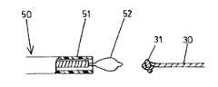
図12は、本発明の第2の参考例の内視鏡用留置バスケット10を示しており、後側のバスケット部Aの後端部に、可撓性チューブ14に代えて短い剛性パイプ製の排出管24を連結し、排出管24の後端部付近に穿設された孔26に糸30を繋いで尾状部材としたものである。
【0036】
糸30の後端部には、回収具を係合させるために、結び目からなる瘤状部31が形成されている。バスケット部A及びその先端部分と連結部分の構成は、第1の参考例と同様である。
【0037】
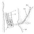
このように構成された第2の参考例の留置バスケット10も、第1の参考例の留置バスケット10と同様にして、図13に示されるように、経内視鏡的に胆道102内に留置し、糸30の結び目によって形成された瘤状部31が十二指腸101内に残るようにしておく。
【0038】
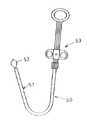
そして、例えば図14に示される内視鏡用スネア状の回収具50の先端ループワイヤ52を、図15と図16にその動作が順に示されるように瘤状部31に引っかけて外套管51の先端内に引き込み、外套管51ごと体外に引き出すことにより留置バスケット10を回収することができる。図14中の53は、先端ループワイヤ52を可撓性チューブ51内に挿脱させてループ径を変化させる操作を行うための操作部である。
【0039】
図17は、本発明の第3の参考例の内視鏡用留置バスケット10を示しており、先側のバスケット部Aを形成する複数の弾性ワイヤ11の先端部分が先端口金12内に差し込まれてそこに銀ロー付け等によって固着、結束されている。
【0040】
また、後側のバスケット部Aを形成する弾性ワイヤ11の基端部分も金属製の接続パイプ32の先側半部内に差し込まれてそこに銀ロー付け等によって固着、結束されており、前後両バスケット部Aの連結部分でも、連結管17の内部に弾性ワイヤ11が通されて固着されている。
【0041】
尾状部材としては、ステンレス鋼線等のような金属製の撚り線40が用いられていて、接続パイプ32の後側半部内に差し込まれてそこに銀ロー付け等によって固着されている。
【0042】
瘤状部41は結び目によって形成されているが、図18に示されるように撚り線40の延出端部に金属パイプを銀ロー付け等によって固着してもよく、要は、その部分を瘤状に部分的に太くすればよい。
【0043】
図19は、本発明の第4の参考例の内視鏡用留置バスケット10を示しており、前側のバスケット部Aを形成する複数の弾性ワイヤ11の先端部分、及び後側のバスケット部Aを形成する複数の弾性ワイヤ11の基端部分が、各々他の結束部材を用いることなく直接銀ロー付け又はレーザー溶接などによって固着、結束されている。また、両バスケット部Aの連結部も複数の弾性ワイヤ11を単に互いに固着することによって形成されている。
【0044】
尾状部材としては、後側のバスケット部Aを形成する複数の弾性ワイヤ11のうちの一本の撚り線40がそのまま後方に延長して用いられており、その撚り線40の端部に、短いワイヤ片が銀ロー付け固定されて瘤状部41を形成している。留置部からの回収は、図14等に示されるスネア型の回収具50等によって行うことができる。
【0045】
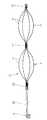
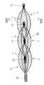
図20は、本発明の第1の実施の形態の内視鏡用留置バスケット10を示しており、直列に連結された隣り合うバスケット部Aにまたがって第3のバスケット部Aを設けたものである。
【0046】
このように構成することにより、バスケット部Aの拡張力がさらに強まって、長い範囲の狭窄部をより確実に拡張させることができる。なお、この実施の形態の内視鏡用留置バスケット10は、図17に示される第3の参考例の留置バスケット10に中間のバスケット部Aを増設した態様を採用しているが、他の参考例の留置バスケット10にバスケット部Aを増設した態様でもよい。
【0047】
図21は、本発明の第2の実施の形態の内視鏡用留置バスケット10を示しており、図20に示される第1の実施の形態の留置バスケット10から、撚り線40の後方に延出する部分(尾状部材)を除いたものである。
【0048】
このように尾状部材を省いても、使用箇所等によっては、例えば図22に示されるような把持鉗子型の回収具60や図23に示されるようなフック型の回収具70をバスケット部Aの後端に直接係合させて留置バスケット10を体腔内から回収することができる。
【0049】
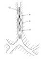
図24は、そのような第2の実施の形態の内視鏡用留置バスケット10が気管支内の狭窄部に留置された状態を示している。なお、各実施の形態の留置バスケット10はいずれも、胆道の狭窄部の拡張だけでなく、気管支や血管の狭窄部の拡張その他各種の目的に使用することができる。
【0050】
図25は、本発明の第3の実施の形態の内視鏡用留置バスケット10を示しており、第2の実施の形態の各バスケット部Aの外面に、図26にXXVI−XXVI断面が示されるようにコラーゲン等を含む網状の膜80を被せたものである。
【0051】
このようにすることにより、長期間留置しても粘膜壁がバスケット部Aの隙間にくい込んでこないので、拡張効果をさらに高めることができる。なお、このような構成も、各参考例の留置バスケット10に採用することができる。
【0052】
【発明の効果】
本発明によれば、自然状態では自己の弾性によってかご状に膨らんで外力によって窄まるように形成されたバスケット部を直列に複数連結したことにより、経内視鏡的に体腔内の管腔臓器内に留置して、狭窄部の範囲が長くても狭窄状態を確実に解除することができる。そして、適宜の回収具を用いることにより、必要に応じて経内視鏡的に狭窄部から容易に取り外すことができる。
【図面の簡単な説明】
【図1】 本発明の第1の参考例の内視鏡用留置バスケットの側面断面図である。
【図2】 図1におけるII−II断面を示す正面断面図である。
【図3】 本発明の第1の参考例の内視鏡用留置バスケットが外套管内にセットされた状態の側面断面図である。
【図4】 本発明の第1の参考例の内視鏡用留置バスケットを狭窄部に挿入する状態の略示断面図である。
【図5】 本発明の第1の参考例の内視鏡用留置バスケットが狭窄部に留置された状態の略示断面図である。
【図6】 本発明の第1の参考例の内視鏡用留置バスケットを狭窄部に挿入する準備状態の内視鏡の側面図である。
【図7】 本発明の第1の参考例の内視鏡用留置バスケットが外套管内にセットされた状態の側面断面図である。
【図8】 本発明の第1の参考例の内視鏡用留置バスケットが外套管から押し出された状態の側面断面図である。
【図9】 本発明の第1の参考例の内視鏡用留置バスケットのバスケット部の形状の他の例を示す側面図である。
【図10】 本発明の第1の参考例の内視鏡用留置バスケットのバスケット部の形状のさらに異なる例を示す側面図である。
【図11】 本発明の第1の参考例の内視鏡用留置バスケットのバスケット部の形状のさらに異なる例を示す側面図である。
【図12】 本発明の第2の参考例の内視鏡用留置バスケットの側面断面図である。
【図13】 本発明の第2の参考例の内視鏡用留置バスケットが狭窄部に留置された状態の略示断面図である。
【図14】 本発明の第2の参考例の内視鏡用留置バスケットを回収するための回収具の外観図である。
【図15】 本発明の第2の参考例の内視鏡用留置バスケットと回収具との係合動作を示す部分側面断面図である。
【図16】 本発明の第2の参考例の内視鏡用留置バスケットと回収具との係合動作を示す部分側面断面図である。
【図17】 本発明の第3の参考例の内視鏡用留置バスケットの側面断面図である。
【図18】 本発明の第3の参考例の内視鏡用留置バスケットの瘤状部の他の例を示す側面部分断面図である。
【図19】 本発明の第4の参考例の内視鏡用留置バスケットの側面図である。
【図20】 本発明の第1の実施の形態の内視鏡用留置バスケットの側面断面図である。
【図21】 本発明の第2の実施の形態の内視鏡用留置バスケットの側面断面図である。
【図22】 本発明の第2の実施の形態の内視鏡用留置バスケットを回収する状態の例を示す側面断面図である。
【図23】 本発明の第2の実施の形態の内視鏡用留置バスケットを回収する状態の異なる例を示す側面断面図である。
【図24】 本発明の第2の実施の形態の内視鏡用留置バスケットが狭窄部に留置された状態の略示断面図である。
【図25】 本発明の第3の実施の形態の内視鏡用留置バスケットの側面断面図である。
【図26】 図25におけるXXVI−XXVI断面を示す正面断面図である。
【符号の説明】
A バスケット部
1 内視鏡
2 処置具挿通チャンネル
10 内視鏡用留置バスケット
11 弾性ワイヤ
12 先端口金
14 可撓性チューブ(尾状部材)
16 牽引用孔(回収具係合部)
17 連結管
21 外套管
23,50,60,70 回収具
30 糸(尾状部材)
31 瘤状部(回収具係合部)
40 撚り線(尾状部材)
41 瘤状部(回収具係合部)[0001]
BACKGROUND OF THE INVENTION
The present invention relates to an indwelling basket for an endoscope that is placed in a stenosis portion through a treatment instrument insertion channel of an endoscope in order to release stenosis of a tubular organ in a body cavity.
[0002]
[Prior art]
When stenosis occurs in the biliary tract due to biliary tract cancer etc., it is difficult for bile fluid to flow from the liver to the duodenum and jaundice symptoms occur, so it is necessary to place a dilator in the stenosis to release the stenosis .
[0003]
Therefore, conventionally, for example, a tube in which a spinous protrusion for retaining is protruded as described in Japanese Utility Model Publication No. 3-35346, or a metal thin wire material as described in Japanese Patent Publication No. 5-54344 is used. A basket formed into a basket-like shape, a net-like tubular stent knitted in a tubular shape, and the like have been placed in the stenosis.
[0004]
[Problems to be solved by the invention]
However, in the tube shown in Japanese Utility Model Publication No. 3-35346, the protrusion formed by protruding in a spine shape is caught on the mucous membrane, and the basket and the net-like tubular stent shown in Japanese Patent Publication No. 5-54344 protrude from the end. A thin wire is caught in the mucous membrane.
[0005]
Therefore, in any case, there is a disadvantage that it cannot be easily removed from the stenosis when it is desired to use it temporarily before surgery or when clogging occurs. In either case, in the case where the range of the stenosis is long, only a part of the stenosis can be expanded, and the stenosis cannot be reliably released.
[0006]
Therefore, the present invention can be placed endoscopically in a luminal organ in a body cavity to reliably release the stenosis even if the stenosis area is long, and if necessary, transendoscopy It is an object of the present invention to provide an indwelling basket for an endoscope that can be easily removed from a narrowed portion by mirror.
[0007]
[Means for Solving the Problems]
In order to achieve the above object, the indwelling basket for an endoscope of the present invention binds at least three elastic wires at the front end and the rear end, and naturally swells in a basket shape by its own elasticity, and is squeezed by an external force. A full basket portion is formed, and a plurality of the basket portions are connected in series.
[0008]
The basket portion may be formed by bending each elastic wire into a smooth curved shape.
Further, the basket portion may be formed by bending each elastic wire in a spiral shape and the basket portion may be formed by bending each elastic wire at an obtuse angle in the middle. Good.
[0009]
The tips of the plurality of elastic wires may be fixed and bound to a hollow cylindrical member, or the tips of the plurality of elastic wires may be directly fixed to each other.
[0010]
In addition, the plurality of basket portions may be housed in an outer tube that is inserted into and removed from the treatment instrument insertion channel of the endoscope, so that the plurality of elastic wires may be constricted. The pushing-out means for pushing out the indwelling basket for an endoscope from the inside of the outer tube is preferably detachable from the outer tube.
[0011]
In addition, the 3rd basket part may be arrange | positioned ranging over the adjacent basket parts connected in series.
Further, a tail-like member extends rearward from the rearmost basket portion of the plurality of basket portions, and engages with a collection tool that is used by being inserted into and removed from the treatment instrument insertion channel of the endoscope. For this purpose, a recovery tool engaging portion may be formed on the extended end portion side of the tail-shaped member.
[0012]
In this case, the tail member may be a tubular body, and the recovery tool engaging portion may be a hole formed in the tail member. Further, the tail-shaped member may be a string-shaped body, and the collection tool engaging portion may be a knob-shaped portion formed at an extended end portion of the string-shaped tail-shaped member.
[0013]
The plurality of baskets may be covered with a mesh.
[0014]
DETAILED DESCRIPTION OF THE INVENTION
Embodiments of the present invention will be described with reference to the drawings.
FIG. 1 shows an
[0015]
Two basket portions A are connected in series to the indwelling
[0016]
In the natural state, each basket portion A swells in a cage shape due to the elasticity of the
[0017]
In addition, in order to form each basket part A, at least 3 or more
[0018]
The tips of the plurality of
[0019]
The connecting
[0020]
In thisreference example , the
[0021]
A flexible tube 14 (tail member) made of synthetic resin is connected to the rear end of the basket portion A on the rear side so as to extend in a tail shape, and the rear ends of the plurality of
[0022]
In order to perform the fixing, a
[0023]
In the vicinity of the rear end portion of the
[0024]
When the
[0025]
Then, as shown in FIG. 4, the
When the distal end portion of the
[0026]
Then, the indwelling
[0027]
As shown in FIG. 5, the vicinity of the rear end of the
[0028]
As a result, bile fluid or the like in the
[0029]
Then, when it becomes necessary to remove the
[0030]
At this time, since the
[0031]
When performing an operation of pushing the
[0032]
Further, as shown in FIG. 7, a basket having a
[0033]
Then, when it becomes necessary to remove the
[0034]
For example, as shown in FIG. 9, the shape of the basket portion A is formed by bending a plurality of
[0035]
FIG. 12 shows an
[0036]
At the rear end portion of the
[0037]
Similarly to the
[0038]
Then, for example, the distal
[0039]
FIG. 17 shows an
[0040]
Further, the base end portion of the
[0041]
As the tail member, a metal stranded
[0042]
Although the knob-
[0043]
FIG. 19 shows an
[0044]
As the tail member, one
[0045]
FIG. 20 shows the
[0046]
By configuring in this way, the expansion force of the basket portion A is further strengthened, and the narrowed portion in a long range can be expanded more reliably. Incidentally, the
[0047]
FIG. 21 shows the
[0048]
Even if the tail member is omitted in this manner, depending on the place of use, for example, the grasping forceps
[0049]
FIG. 24 shows a state in which the
[0050]
FIG. 25 shows an
[0051]
By doing in this way, even if it is left for a long time, the mucosal wall does not get into the gap of the basket portion A, so that the expansion effect can be further enhanced. In addition, such a structure can also be employ | adopted for the
[0052]
【The invention's effect】
According to the present invention, a plurality of basket parts formed in a natural state so as to be swelled in a basket shape by its own elasticity and constricted by an external force are connected in series, so that a luminal organ in a body cavity is transendoscopically. The stenosis state can be reliably released even if the stenosis portion is long in range. Then, by using an appropriate recovery tool, it can be easily removed from the stenosis portion endoscopically as necessary.
[Brief description of the drawings]
FIG. 1 is a side sectional view of an indwelling basket for an endoscope according to a firstreference example of the present invention.
FIG. 2 is a front sectional view showing a II-II section in FIG. 1;
FIG. 3 is a side cross-sectional view showing a state in which the endoscope indwelling basket according to the firstreference example of the present invention is set in the outer tube.
FIG. 4 is a schematic cross-sectional view showing a state in which the endoscope indwelling basket according to the firstreference example of the present invention is inserted into the narrowed portion.
FIG. 5 is a schematic cross-sectional view showing a state in which the endoscope indwelling basket according to the firstreference example of the present invention is placed in the narrowed portion.
FIG. 6 is a side view of the endoscope in a ready state for inserting the indwelling basket for an endoscope according to the firstreference example of the present invention into the narrowed portion.
FIG. 7 is a side cross-sectional view showing a state in which the endoscope indwelling basket according to the firstreference example of the present invention is set in the outer tube.
FIG. 8 is a side sectional view showing a state in which the endoscope indwelling basket according to the firstreference example of the present invention is pushed out of the outer tube.
FIG. 9 is a side view showing another example of the shape of the basket portion of the indwelling basket for an endoscope according to the firstreference example of the present invention.
FIG. 10 is a side view showing still another example of the shape of the basket portion of the indwelling basket for an endoscope according to the firstreference example of the present invention.
FIG. 11 is a side view showing still another example of the shape of the basket portion of the indwelling basket for an endoscope according to the firstreference example of the present invention.
FIG. 12 is a side sectional view of an indwelling basket for an endoscope according to a secondreference example of the present invention.
FIG. 13 is a schematic cross-sectional view showing a state in which the endoscope indwelling basket according to the secondreference example of the present invention is indwelled in the narrowed portion.
FIG. 14 is an external view of a collecting tool for collecting an indwelling basket for an endoscope according to a secondreference example of the present invention.
FIG. 15 is a partial side cross-sectional view showing an engagement operation between an indwelling basket for an endoscope and a collection tool according to a secondreference example of the present invention.
FIG. 16 is a partial side cross-sectional view showing an engaging operation between an indwelling basket for an endoscope and a collection tool according to a secondreference example of the present invention.
FIG. 17 is a side sectional view of an indwelling basket for an endoscope according to a thirdreference example of the present invention.
FIG. 18 is a side partial cross-sectional view showing another example of a knob-like portion of an indwelling basket for an endoscope according to a thirdreference example of the present invention.
FIG. 19 is a side view of an indwelling basket for an endoscope according to a fourthreference example of the present invention.
FIG. 20 is a side sectional view of the indwelling basket for an endoscope according to thefirst embodiment of the present invention.
FIG. 21 is a side sectional view of an indwelling basket for an endoscope according to asecond embodiment of the present invention.
FIG. 22 is a side sectional view showing an example of a state in which the endoscope indwelling basket according to thesecond embodiment of the present invention is collected.
FIG. 23 is a side cross-sectional view showing a different example of a state in which the endoscope indwelling basket according to thesecond embodiment of the present invention is collected.
FIG. 24 is a schematic cross-sectional view of a state in which the endoscope indwelling basket according to thesecond embodiment of the present invention is indwelled in the narrowed portion.
FIG. 25 is a side sectional view of an indwelling basket for an endoscope according to athird embodiment of the present invention.
26 is a front sectional view showing a XXVI-XXVI section in FIG. 25. FIG.
[Explanation of symbols]
A
16 Towing hole (collecting tool engaging part)
17 Connecting
31 Knurled part (collecting tool engaging part)
40 Stranded wire (tail-shaped member)
41 Knurled part (collecting tool engaging part)
Claims (14)
Translated fromJapanesePriority Applications (1)
| Application Number | Priority Date | Filing Date | Title |
|---|---|---|---|
| JP27559597AJP3995770B2 (en) | 1997-10-08 | 1997-10-08 | Endoscope indwelling basket |
Applications Claiming Priority (1)
| Application Number | Priority Date | Filing Date | Title |
|---|---|---|---|
| JP27559597AJP3995770B2 (en) | 1997-10-08 | 1997-10-08 | Endoscope indwelling basket |
Publications (2)
| Publication Number | Publication Date |
|---|---|
| JPH11114070A JPH11114070A (en) | 1999-04-27 |
| JP3995770B2true JP3995770B2 (en) | 2007-10-24 |
Family
ID=17557643
Family Applications (1)
| Application Number | Title | Priority Date | Filing Date |
|---|---|---|---|
| JP27559597AExpired - Fee RelatedJP3995770B2 (en) | 1997-10-08 | 1997-10-08 | Endoscope indwelling basket |
Country Status (1)
| Country | Link |
|---|---|
| JP (1) | JP3995770B2 (en) |
Families Citing this family (9)
| Publication number | Priority date | Publication date | Assignee | Title |
|---|---|---|---|---|
| JP4298244B2 (en)* | 2002-09-06 | 2009-07-15 | マニー株式会社 | Stent |
| JP4081522B2 (en)* | 2003-05-23 | 2008-04-30 | 新 石丸 | Temporary indwelling stent and stent graft |
| WO2015072366A1 (en) | 2013-11-12 | 2015-05-21 | オリンパスメディカルシステムズ株式会社 | Basket forceps |
| WO2015072394A1 (en) | 2013-11-12 | 2015-05-21 | オリンパスメディカルシステムズ株式会社 | Basket-type grasping forceps |
| JP5869190B2 (en) | 2013-12-12 | 2016-02-24 | オリンパス株式会社 | Basket-type grasping forceps |
| CN108144177B (en)* | 2016-12-06 | 2021-04-30 | 上海理工大学 | Cross-ball esophageal dilator |
| KR102131399B1 (en)* | 2017-05-24 | 2020-07-08 | 고려대학교산학협력단 | Apparatus for repositioning a nasobiliary catheter from mouth to nostril |
| JP2023545058A (en)* | 2020-10-08 | 2023-10-26 | ゼンフロー, インコーポレイテッド | Systems, devices, and methods for retrieval of implants within the prostatic urethra |
| CN118750098B (en)* | 2024-09-06 | 2025-02-07 | 湖南省华芯医疗器械有限公司 | A front end component of a stone-taking net basket and a stone-taking net basket |
- 1997
- 1997-10-08JPJP27559597Apatent/JP3995770B2/ennot_activeExpired - Fee Related
Also Published As
| Publication number | Publication date |
|---|---|
| JPH11114070A (en) | 1999-04-27 |
Similar Documents
| Publication | Publication Date | Title |
|---|---|---|
| JP3527619B2 (en) | Endoscope stent | |
| JP4198759B2 (en) | Stent delivery system | |
| US6514281B1 (en) | System for delivering bifurcation stents | |
| JP4043216B2 (en) | Stent | |
| JP4546481B2 (en) | Removable stent | |
| ES2264257T3 (en) | MINIMUM ACCESS MEDICAL RECOVERY DEVICE. | |
| US7993302B2 (en) | Clot retrieval device | |
| JP3876246B2 (en) | Catheter for positioning of intraluminal grafts using a guide wire | |
| EP2355717B1 (en) | Systems for capturing and removing urinary stones from body cavities | |
| JP3662885B2 (en) | Artificial vascular stent and stent insertion device | |
| ES2387911T3 (en) | Tied spiral for the treatment of body lumens | |
| JP2020171796A (en) | Biliary stents | |
| JP3075355B2 (en) | Basket type grasping forceps | |
| JP6194381B2 (en) | Collection device | |
| WO2009150920A1 (en) | Medical treatment tool for tubular organs | |
| JPH10510445A (en) | Surgical expandable body tube for expanding a body conduit | |
| WO1991012047A1 (en) | Resilient and bendable instrument inserted into human organ and device for bending said instrument | |
| JP2003116982A (en) | System for drainage of gallbladder through duodenum under endoscope | |
| JP2002537065A (en) | Catheter assembly with endoluminal prosthesis and method of placement thereof | |
| BRPI0608247A2 (en) | catheter system for clearing forked vessels | |
| EP1690498A3 (en) | Vascular retractor | |
| JP3995770B2 (en) | Endoscope indwelling basket | |
| HU220981B1 (en) | An aggregate for transluminal insertion of a tubular stent, and an endovascular graft device | |
| JP4043210B2 (en) | Stent | |
| JPWO2016129551A1 (en) | Stent |
Legal Events
| Date | Code | Title | Description |
|---|---|---|---|
| A621 | Written request for application examination | Free format text:JAPANESE INTERMEDIATE CODE: A621 Effective date:20040804 | |
| A977 | Report on retrieval | Free format text:JAPANESE INTERMEDIATE CODE: A971007 Effective date:20061228 | |
| A131 | Notification of reasons for refusal | Free format text:JAPANESE INTERMEDIATE CODE: A131 Effective date:20070315 | |
| A521 | Written amendment | Free format text:JAPANESE INTERMEDIATE CODE: A523 Effective date:20070509 | |
| TRDD | Decision of grant or rejection written | ||
| A01 | Written decision to grant a patent or to grant a registration (utility model) | Free format text:JAPANESE INTERMEDIATE CODE: A01 Effective date:20070726 | |
| A61 | First payment of annual fees (during grant procedure) | Free format text:JAPANESE INTERMEDIATE CODE: A61 Effective date:20070801 | |
| FPAY | Renewal fee payment (event date is renewal date of database) | Free format text:PAYMENT UNTIL: 20100810 Year of fee payment:3 | |
| R150 | Certificate of patent or registration of utility model | Free format text:JAPANESE INTERMEDIATE CODE: R150 | |
| FPAY | Renewal fee payment (event date is renewal date of database) | Free format text:PAYMENT UNTIL: 20100810 Year of fee payment:3 | |
| FPAY | Renewal fee payment (event date is renewal date of database) | Free format text:PAYMENT UNTIL: 20100810 Year of fee payment:3 | |
| S111 | Request for change of ownership or part of ownership | Free format text:JAPANESE INTERMEDIATE CODE: R313111 | |
| FPAY | Renewal fee payment (event date is renewal date of database) | Free format text:PAYMENT UNTIL: 20100810 Year of fee payment:3 | |
| R360 | Written notification for declining of transfer of rights | Free format text:JAPANESE INTERMEDIATE CODE: R360 | |
| S111 | Request for change of ownership or part of ownership | Free format text:JAPANESE INTERMEDIATE CODE: R313115 | |
| FPAY | Renewal fee payment (event date is renewal date of database) | Free format text:PAYMENT UNTIL: 20100810 Year of fee payment:3 | |
| R370 | Written measure of declining of transfer procedure | Free format text:JAPANESE INTERMEDIATE CODE: R370 | |
| FPAY | Renewal fee payment (event date is renewal date of database) | Free format text:PAYMENT UNTIL: 20100810 Year of fee payment:3 | |
| R350 | Written notification of registration of transfer | Free format text:JAPANESE INTERMEDIATE CODE: R350 | |
| FPAY | Renewal fee payment (event date is renewal date of database) | Free format text:PAYMENT UNTIL: 20100810 Year of fee payment:3 | |
| FPAY | Renewal fee payment (event date is renewal date of database) | Free format text:PAYMENT UNTIL: 20110810 Year of fee payment:4 | |
| FPAY | Renewal fee payment (event date is renewal date of database) | Free format text:PAYMENT UNTIL: 20120810 Year of fee payment:5 | |
| FPAY | Renewal fee payment (event date is renewal date of database) | Free format text:PAYMENT UNTIL: 20120810 Year of fee payment:5 | |
| S111 | Request for change of ownership or part of ownership | Free format text:JAPANESE INTERMEDIATE CODE: R313117 | |
| FPAY | Renewal fee payment (event date is renewal date of database) | Free format text:PAYMENT UNTIL: 20120810 Year of fee payment:5 | |
| R350 | Written notification of registration of transfer | Free format text:JAPANESE INTERMEDIATE CODE: R350 | |
| RD02 | Notification of acceptance of power of attorney | Free format text:JAPANESE INTERMEDIATE CODE: R3D02 | |
| FPAY | Renewal fee payment (event date is renewal date of database) | Free format text:PAYMENT UNTIL: 20120810 Year of fee payment:5 | |
| FPAY | Renewal fee payment (event date is renewal date of database) | Free format text:PAYMENT UNTIL: 20130810 Year of fee payment:6 | |
| R250 | Receipt of annual fees | Free format text:JAPANESE INTERMEDIATE CODE: R250 | |
| S533 | Written request for registration of change of name | Free format text:JAPANESE INTERMEDIATE CODE: R313533 | |
| S111 | Request for change of ownership or part of ownership | Free format text:JAPANESE INTERMEDIATE CODE: R313114 | |
| S111 | Request for change of ownership or part of ownership | Free format text:JAPANESE INTERMEDIATE CODE: R313114 | |
| S533 | Written request for registration of change of name | Free format text:JAPANESE INTERMEDIATE CODE: R313533 | |
| R350 | Written notification of registration of transfer | Free format text:JAPANESE INTERMEDIATE CODE: R350 | |
| R250 | Receipt of annual fees | Free format text:JAPANESE INTERMEDIATE CODE: R250 | |
| R250 | Receipt of annual fees | Free format text:JAPANESE INTERMEDIATE CODE: R250 | |
| R250 | Receipt of annual fees | Free format text:JAPANESE INTERMEDIATE CODE: R250 | |
| LAPS | Cancellation because of no payment of annual fees |