JP3995706B2 - Electrostatic chuck device - Google Patents
Electrostatic chuck deviceDownload PDFInfo
- Publication number
- JP3995706B2 JP3995706B2JP2006552399AJP2006552399AJP3995706B2JP 3995706 B2JP3995706 B2JP 3995706B2JP 2006552399 AJP2006552399 AJP 2006552399AJP 2006552399 AJP2006552399 AJP 2006552399AJP 3995706 B2JP3995706 B2JP 3995706B2
- Authority
- JP
- Japan
- Prior art keywords
- electrostatic chuck
- power feeding
- electrode pattern
- area
- electrode
- Prior art date
- Legal status (The legal status is an assumption and is not a legal conclusion. Google has not performed a legal analysis and makes no representation as to the accuracy of the status listed.)
- Expired - Fee Related
Links
Images


Classifications
- H—ELECTRICITY
- H02—GENERATION; CONVERSION OR DISTRIBUTION OF ELECTRIC POWER
- H02N—ELECTRIC MACHINES NOT OTHERWISE PROVIDED FOR
- H02N13/00—Clutches or holding devices using electrostatic attraction, e.g. using Johnson-Rahbek effect
- H—ELECTRICITY
- H01—ELECTRIC ELEMENTS
- H01L—SEMICONDUCTOR DEVICES NOT COVERED BY CLASS H10
- H01L21/00—Processes or apparatus adapted for the manufacture or treatment of semiconductor or solid state devices or of parts thereof
- H01L21/67—Apparatus specially adapted for handling semiconductor or electric solid state devices during manufacture or treatment thereof; Apparatus specially adapted for handling wafers during manufacture or treatment of semiconductor or electric solid state devices or components ; Apparatus not specifically provided for elsewhere
- H01L21/683—Apparatus specially adapted for handling semiconductor or electric solid state devices during manufacture or treatment thereof; Apparatus specially adapted for handling wafers during manufacture or treatment of semiconductor or electric solid state devices or components ; Apparatus not specifically provided for elsewhere for supporting or gripping
- H01L21/687—Apparatus specially adapted for handling semiconductor or electric solid state devices during manufacture or treatment thereof; Apparatus specially adapted for handling wafers during manufacture or treatment of semiconductor or electric solid state devices or components ; Apparatus not specifically provided for elsewhere for supporting or gripping using mechanical means, e.g. chucks, clamps or pinches
- H—ELECTRICITY
- H01—ELECTRIC ELEMENTS
- H01L—SEMICONDUCTOR DEVICES NOT COVERED BY CLASS H10
- H01L21/00—Processes or apparatus adapted for the manufacture or treatment of semiconductor or solid state devices or of parts thereof
- H01L21/67—Apparatus specially adapted for handling semiconductor or electric solid state devices during manufacture or treatment thereof; Apparatus specially adapted for handling wafers during manufacture or treatment of semiconductor or electric solid state devices or components ; Apparatus not specifically provided for elsewhere
- H01L21/683—Apparatus specially adapted for handling semiconductor or electric solid state devices during manufacture or treatment thereof; Apparatus specially adapted for handling wafers during manufacture or treatment of semiconductor or electric solid state devices or components ; Apparatus not specifically provided for elsewhere for supporting or gripping
- H01L21/6831—Apparatus specially adapted for handling semiconductor or electric solid state devices during manufacture or treatment thereof; Apparatus specially adapted for handling wafers during manufacture or treatment of semiconductor or electric solid state devices or components ; Apparatus not specifically provided for elsewhere for supporting or gripping using electrostatic chucks
- H01L21/6833—Details of electrostatic chucks
Landscapes
- Engineering & Computer Science (AREA)
- Physics & Mathematics (AREA)
- Condensed Matter Physics & Semiconductors (AREA)
- General Physics & Mathematics (AREA)
- Manufacturing & Machinery (AREA)
- Computer Hardware Design (AREA)
- Microelectronics & Electronic Packaging (AREA)
- Power Engineering (AREA)
- Container, Conveyance, Adherence, Positioning, Of Wafer (AREA)
- Constituent Portions Of Griding Lathes, Driving, Sensing And Control (AREA)
Description
Translated fromJapanese 本発明は、例えば液晶ディスプレー(LCD)やプラズマディスプレー(PDP)などのフラットパネルディスプレーの製造過程において、CFガラスやTFTガラスなどのガラス製基板か又は合成樹脂製基板などのワークを吸着保持して貼り合わせる基板貼り合わせ機を含む基板組立装置や、基板を搬送する基板搬送装置、或いはシリコンウエハなどのワークを加工する半導体製造装置などに用いられる静電チャック装置に関する。
詳しくは、ワークと対向して面状に配置された電極に、電圧を印加することでワークを静電吸着する静電チャック装置に関する。In the manufacturing process of a flat panel display such as a liquid crystal display (LCD) and a plasma display (PDP), for example, the present invention holds a workpiece such as a glass substrate such as CF glass or TFT glass or a synthetic resin substrate. The present invention relates to an electrostatic chuck device used for a substrate assembly apparatus including a substrate bonding machine to be bonded, a substrate transfer apparatus for transferring a substrate, or a semiconductor manufacturing apparatus for processing a workpiece such as a silicon wafer.
More specifically, the present invention relates to an electrostatic chuck device that electrostatically attracts a workpiece by applying a voltage to an electrode arranged in a plane facing the workpiece.
従来、真空中で二枚の基板を重ね合わせる基板貼り合わせ機では、静電チャックで基板を保持していたが、近年の基板の大型化に伴い、大きなサイズの静電チャックを製作することが難しくなり、また仮に製作できても非常に高価な物となっていた。
そこで、これらの問題を解決するため、大型基板に対応するために、複数の静電チャックを並べて配置した静電チャック装置がある。
このような静電チャック装置の一例として、大型のワーク(被吸着体)を吸着できる面積の台座(ベース板)に、2枚以上の静電チャックを面一に接合して固定すると共に、各静電チャックの内部電極に導通する電極端子が、ベース板の貫通穴を通じて台座の裏側から相互に電気配線されることにより、静電チャックユニットを構成したものもある(例えば、特許文献1参照)。Conventionally, in a substrate bonding machine that superimposes two substrates in a vacuum, the substrate is held by an electrostatic chuck. However, as the size of the substrate increases in recent years, it is possible to manufacture a large size electrostatic chuck. Even if it was difficult to manufacture, it was very expensive.
In order to solve these problems, there is an electrostatic chuck device in which a plurality of electrostatic chucks are arranged side by side to cope with a large substrate.
As an example of such an electrostatic chuck device, two or more electrostatic chucks are joined and fixed to a pedestal (base plate) having an area capable of attracting a large workpiece (subject to be attracted). In some cases, the electrostatic chuck unit is configured by electrically connecting the electrode terminals that are electrically connected to the internal electrode of the electrostatic chuck from the back side of the base through the through holes of the base plate (for example, see Patent Document 1). .
このような静電チャック装置を用いた液晶ディスプレーの生産ラインなどでは、特にセットアップ中にガラスのカレット(破片)などがガラス基板上に運搬されることがあり、基板との静電吸着に伴って該カレットを静電チャックとの間に噛み込むことで、この静電チャックの膜面が部分的に破壊して故障することがある。
静電チャックの膜面が一部分でも破壊すると、この静電チャック全体の機能が停止すると共に、高電圧がかかる電極が露出するため、特に真空中貼り合わせ機のような真空に近い状態で用いられる場合には、金属製台座のアース部との間でアーク放電したり、或いは真空引きの際のパッシェン領域においてプラズマ放電するなど、過電流を引き起こす不具合が生ずる恐れがあった。
この点において、特許文献1の場合には、2枚以上の静電チャックが配置されるため、膜面が破壊された静電チャックを除いてそれ以外の静電チャックは使用可能であるが、膜面の一部分が破壊された静電チャックは現場での修理ができないため、上述した放電を防止するには、膜面の一部分が破壊された静電チャック自体を交換しなければならず、コストアップになると共に、この交換作業が完了するまでライン全体の稼働を再開できないことから、稼働率が低下するという問題があった。
このような静電チャックの交換に要する時間を短縮化するには、予め静電チャックの予備品を設置場所近くに常時保有しなければならず、トータルコストが高くなるという問題があった。In the production line of liquid crystal displays using such an electrostatic chuck device, glass cullet (shards) may be transported on the glass substrate, especially during setup, and accompanying electrostatic adsorption with the substrate By biting the cullet between the electrostatic chuck and the electrostatic chuck, the film surface of the electrostatic chuck may be partially broken and broken.
If even a part of the surface of the electrostatic chuck breaks, the function of the entire electrostatic chuck stops and the electrode to which a high voltage is applied is exposed, so that it is used in a state close to a vacuum, particularly in a vacuum laminating machine. In such a case, there has been a risk of causing an overcurrent, such as arc discharge between the metal pedestal and the earth, or plasma discharge in the Paschen region during evacuation.
In this respect, in the case of
In order to shorten the time required for replacement of such an electrostatic chuck, a spare part of the electrostatic chuck has to be always kept in the vicinity of the installation place in advance, resulting in a problem that the total cost increases.
本発明のうち請求項1記載の発明は、簡単な処理で短時間にワークを吸着可能に復帰させると共に、各エリアの切断作業を容易にしながら切断作業に伴う裂け目の拡散による電極の二次的な被害を防止することを目的としたものである。
請求項2記載の発明は、請求項1に記載の発明の目的に加えて、給電部の切断処理に伴って部分的に突出してもワークへの悪影響を抑制することを目的としたものである。
請求項3記載の発明は、請求項2に記載の発明の目的に加えて、選択的な切断部分と金属台座との放電を防止することを目的としたものである。
請求項4記載の発明は、請求項1、2または3に記載の発明の目的に加えて、簡便で且つ確実な封止処理を短時間に行えると共に封止部材の再使用を可能にすることを目的としたものである。According to the first aspect of the present invention, the work can be returned to be suckable in a short time by a simple process, and thesecondary electrode is formed by the diffusion of the cracks accompanying the cutting operation while facilitating the cutting operation of each area. The purpose isto prevent serious damage .
According to asecond aspect of the invention, in addition to the object ofthe invention describedin
According to athird aspectof the invention, in addition to the object of the invention described in
The invention of
前述した目的を達成するために、本発明のうち請求項1記載の発明は、電極をワークと平行な平面内で複数のエリアに分割し、これらエリア毎に独立する電極パターンを夫々設けると共に、各電極パターンへの給電部をエリア毎に夫々設け、前記複数の給電部を、相互に接近させて平行に並べると共に、これら給電部に隣接する誘電層部分に、該給電部に沿って平行なスリットを切欠形成し、各スリットから刃物で任意の給電部を選択的に切断処理可能にして、破壊したエリアに配置された電極パターンへの給電を部分的に停止させたことを特徴とするものである。
請求項2記載の発明は、請求項1記載の発明の構成に、前記給電部と対向する台座に凹部を形成した構成を加えたことを特徴とする。
請求項3記載の発明は、請求項2記載の発明の構成に、前記給電部の選択的に切断された任意の切断部分を台座の凹部内で封止した構成を加えたことを特徴とする。
請求項4記載の発明は、請求項1、2または3記載の発明の構成に、前記給電部の選択的に切断された任意の切断部分を囲むように環状シール材を配置して封止した構成を加えたことを特徴とする。In order to achieve the above-mentioned object, the invention according to
The invention described in
The invention according to
According to a fourth aspect of the present invention, in the configuration of the first, second, or third aspect of the invention, an annular sealing material is disposed and sealed so as to surround an arbitrary cut portion of the power feeding portion. It is characterized by adding a configuration.
本発明のうち請求項1記載の発明は、電極をワークと平行な平面内で複数のエリアに分割し、これらエリア毎に独立する電極パターンを夫々設けると共に、各電極パターンへの給電部をエリア毎に夫々設け、任意の給電部を切断して、任意のエリアに配置された電極パターンへの給電を部分的に停止させることにより、複数のエリアのうち一部の膜面が破壊された場合であっても、この破壊されたエリア内の電極パターンは静電チャックとして選択的に機能しないが、それ以外のエリアの電極パターンは静電チャックとして機能する。
従って、簡単な処理で短時間にワークを吸着可能に復帰させることができる。
その結果、膜面破壊による放電を防止するには膜面が破壊された静電チャック自体を交換する必要がある従来のものに比べ、膜面の一部分が破壊しても放電防止のためにその静電チャック全体を交換する必要がなくなって、数回の補修が可能となり、トータルコストを低減できると共に、静電チャックの予備品の保有数も低減できる。
特に本発明の静電チャック装置を液晶ディスプレーの生産ラインなどに用いた場合には、膜面の一部分が破壊しても放電を確実に防止できると共に、ライン全体の稼働を短時間で再開できるから、稼働率が低下せず、安定した生産量を期待できる。
更に、複数の給電部を、相互に接近させて平行に並べると共に、これら給電部に隣接する誘電層部分に、該給電部に沿って平行なスリットを切欠形成することにより、スリットからカッターやハサミなどの刃物を挿入すれば、狙った給電部の一つが切断可能になると共に、その切断端縁から電極を構成するフィルムなどに裂け目が発生することもない。
従って、各エリアの切断作業を容易にしながら切断作業に伴う裂け目の拡散による電極の二次的な被害を防止することができる。According to the first aspect of the present invention, the electrode is divided into a plurality of areas in a plane parallel to the workpiece, and an independent electrode pattern is provided for each of the areas, and a power feeding portion to each electrode pattern is provided in the area. When each part of the film surface is destroyed by cutting off any power supply unit and partially stopping power supply to the electrode pattern placed in any area Even so, the electrode pattern in the destroyed area does not selectively function as an electrostatic chuck, but the electrode pattern in other areas functions as an electrostatic chuck.
Therefore, it is possible to return the workpiece so that it can be sucked in a short time with a simple process.
As a result, in order to prevent discharge due to film surface destruction, it is necessary to replace the electrostatic chuck itself whose film surface is broken. Since it is not necessary to replace the entire electrostatic chuck, the repair can be performed several times, the total cost can be reduced, and the number of spare parts for the electrostatic chuck can be reduced.
In particular, when the electrostatic chuck device of the present invention is used in a liquid crystal display production line or the like, even if a part of the film surface is broken, it is possible to reliably prevent discharge and to restart the operation of the entire line in a short time. The operation rate does not decrease, and stable production can be expected.
Further, a plurality of feeding parts, together with arranging theflat rowis brought closer to each other, the dielectric layer portion adjacent thereto feeding unit, by the notch forming aflat line slitalong the power feeding unit, a cutter from the slit If a blade such as a scissor is inserted, one of the targeted power feeding portions can be cut, and no tears will occur in the film constituting the electrode from the cut edge.
Accordingly, it is possible to prevent secondary damage to the electrodes due to the diffusion of the cracks accompanying the cutting operation while facilitating the cutting operation of each area.
請求項2の発明は、請求項1の発明の効果に加えて、給電部と対向する台座に凹部を形成することにより、給電部の切断で、この給電部の切断部分がワークへ向けて凸状に突出した形状になっても、ワークの静電吸着時にこの切断凸状部が上記凹部内に入り込んで、ワークに対し部分的に圧接しない。
従って、給電部の切断処理に伴って部分的に突出してもワークへの悪影響を抑制することができる。In the invention of
Therefore, even if it partially protrudes along with the cutting process of the power feeding unit, it is possible to suppress adverse effects on the workpiece.
請求項3の発明は、請求項2の発明の効果に加えて、給電部の選択的な切断部分を台座の凹部内で封止することにより、給電部の選択的な切断部分が露出しない。
従って、選択的な切断部分と金属台座との放電を防止することができる。According to the invention of
Therefore, it is possible to prevent discharge between the selectively cut portion and the metal base.
請求項4の発明は、請求項1、2または3の発明の効果に加えて、給電部の選択的な切断部分を囲むように環状シール材を配置して封止することにより、切断部分とその外部雰囲気とが環状シール材を介して遮断される。
従って、簡便で且つ確実な封止処理を短時間に行えると共に封止部材の再使用を可能にすることができる。According to the invention of
Therefore, a simple and reliable sealing process can be performed in a short time and the sealing member can be reused.
本発明の静電チャック装置Aが、ワークWとして液晶ディスプレー(LCD)パネルなどのガラス基板を静電吸着して貼り合わせる基板貼り合わせ機に配備された場合を示す。
この基板貼り合わせ機は、上下一対配備された保持板11の対向面にワークWとして2枚の基板を夫々保持させ、それらの周囲に区画形成された閉空間(図示せず)内が所定の真空度に達してから、上下保持板を相対的にXYθ方向へ調整移動し、基板同士の位置合わせが行われ、その後、上保持板から上基板を強制的に剥離して下基板上の環状接着剤又はシール材(図示せず)へ瞬間的に圧着することにより、両者間を封止して重ね合わせ、その後は、両基板の内外に生じる気圧差で両基板の間を所定のギャップまで加圧して貼り合わせ工程が完了するものである。The case where the electrostatic chuck apparatus A of the present invention is installed in a substrate laminating machine that electrostatically attracts and bonds a glass substrate such as a liquid crystal display (LCD) panel as the work W is shown.
This substrate laminating machine holds two substrates as workpieces W on the opposing surfaces of a pair of upper and
そして、上記保持板11の基板側には、その全体に亘って本発明の静電チャック装置Aを配備するか、又は複数の静電チャック装置Aを互いに接合して夫々の吸着面が面一となるように並列状に配備することにより、大型のワーク(基板)Wでも確実に吸着保持可能にしている。 Then, the electrostatic chuck device A of the present invention is provided on the entire substrate side of the
本発明の静電チャック装置Aは、図1〜図5に示す如く、ワークWと対向して面状に形成された電極1と、この電極1に積層される誘電層2と、これらに沿ってワークWと反対側に設けられた台座3とからなるフィルム状又は板状の積層構造体であり、この台座3の裏面3aを上記保持板11の基板側表面11aに対して着脱自在に取り付けている。 As shown in FIGS. 1 to 5, the electrostatic chuck device A of the present invention has an
上記誘電層2は、例えばポリイミド、ポリエーテルエーテルケトン(PEEK)、ポリエチレンナフタレート(PEN)などのエンジニアリングプラスチックからなる弾性変形可能な絶縁性有機材料で、2層又は3層以上又は一層のフィルム状に形成するか、或いは例えばAl2O3、SiC、AlN、Zr2O3などのセラミックスやそれ以外の無機材料などにより薄板状に形成し、面状に形成された電極1の両面か又はワーク側表面のみに接着して積層する。The
上記電極1のワーク側表面にポリイミドやPEEKなどの有機材料製の誘電層2を積層した場合には、電気的特性に優れるという利点があり、セラミックス製の誘電層2を積層した場合には、この誘電層2自体が硬くなって、ワークWとの間にガラスのカレット(破片)などの硬い異物を噛み込んだ時でも誘電層2が傷付き難くなるという利点がある。 When the
更に、前記誘電層2の裏面又は電極1の裏面と台座3とは、粘着材又は接着剤などの接着層(図示せず)を挟んで一体的に貼り付けられる。 Furthermore, the back surface of the
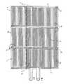
また、前記電極1は、図1及び図4に示す如く、ワークWと平行な平面内で複数にエリア1aに分割されて、これらエリア1a毎に独立する電極パターン1bを夫々設けると共に、各電極パターン1bへの給電を個別に制御するための給電部1cをエリア1a毎に夫々設け、任意の給電部1cを後述する切断方法で切断処理することにより、任意のエリア1aに配置された電極パターン1bへの給電を部分的に停止させるようにしている。 As shown in FIGS. 1 and 4, the
これら複数の給電部1cは、図1に示す如く、上記ワークWと対向して電極パターン1bを設けた静電チャック機能面1′の内側領域に配置されるか、又は図4に示す如く、静電チャック機能面1′の外側領域に配置されると共に、図示例の如く、複数の給電部1cのうちエリア1aが近いもの同士を夫々集めて各エリア1a近傍の複数箇所に夫々分散配置するか、或いは全ての給電部1cを所定箇所に集中配置することが好ましい。 The plurality of
このように複数の給電部1cを集めて配置した場合には、図2に示す如く、相互に接近させて略平行に並べると共に、これら給電部1cの近傍及びそれに積層された前記誘電層2には、該給電部1cに沿って略平行な適宜長さのスリット(切れ目)1dを予め切欠形成することにより、各スリット1dに対して例えばカッターやハサミなどの刃物(図示せず)を後工程で挿入可能にすると共に、該刃物で任意の給電部1cだけを選択的に切断処理可能にしている。
図示例では、略平行に並べられた給電部1cの間に複数のスリット(切れ目)1dを略平行に切欠形成している。When the plurality of
In the illustrated example, a plurality of slits (cuts) 1d are formed in a substantially parallel notch between the
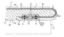
上記複数の給電部1cの裏面側及び電極パターン1bの裏面側は、図3又は図5に示す如く、前記誘電層2又は接着層を介して台座3と対向しており、各給電部1cと対向する位置には凹部3bが形成され、上述した選択的な切断処理で任意の給電部1cの切断部分1c′がワークWへ向けて凸状に突出した形状になっても、ワークWの静電吸着時において、この切断凸状部を上記凹部3b内に入り込ませる構造にすることにより、ワークWに対して切断凸状部が他の部分に比べて部分的に強く圧接しないようにする。 As shown in FIG. 3 or FIG. 5, the back surface side of the plurality of
更に、上記台座3が例えばアルミニウムなどの金属やそれ以外の導電材料で形成される場合には、絶縁性材料からなる絶縁体4を介して、上述した切断処理で選択的に切断された任意の給電部1cの切断部分1c′を封止処理することにより、高電圧のかかる切断部分1c′が暴露されるのを防止して、「プラズマ放電」や「アーク放電」などの現象が発生しないようにする。
以下、本発明の各実施例を図面に基づいて説明する。Further, when the
Embodiments of the present invention will be described below with reference to the drawings.
この実施例1は、図1〜図3に示す如く、前記電極パターン1bが+極の電極と−極の電極を有する双極型の静電チャックであり、これら+極と−極の電極パターン1bを、ポリイミドやポリエーテルエーテルケトン(PEEK)などのエンジニアリングプラスチックからなる誘電層2の間に挿入封止すると共に、前記複数の給電部1cを静電チャック機能面1′の内側領域に分散配置することで、一体構造の静電チャックフィルムが構成され、この静電チャックフィルムを金属製の台座3に接着して、上記給電部1cと対向するように凹部3bが台座3の表面3cに形成された場合を示すものである。 In the first embodiment, as shown in FIGS. 1 to 3, the
図示例では、前記エリア1aが矩形状で、上記電極パターン1bの+極と−極が、同一平面上で互いに嵌り合う櫛歯形状に夫々形成されており、例えば約500mm×300mmのエリア1aに一対の電極パターン1bを互いに嵌り合うように配置している。 In the illustrated example, the
また、図示例以外の電極構造としては、例えば特開2005−64105号公報に開示されるような、ポリイミドフィルムなどの絶縁性材料からなる誘電層(絶縁層)を挟んでその両面に沿って第一の電極パターンと第二の電極パターンとを積層すると共に、これら両電極パターンの表面をポリイミドフィルムなどの誘電層(絶縁性薄膜)で被覆した静電チャックや単極型の静電チャックを使用することも可能である。 Further, as an electrode structure other than the illustrated example, a dielectric layer (insulating layer) made of an insulating material such as a polyimide film as disclosed in, for example, Japanese Patent Application Laid-Open No. 2005-64105 is sandwiched along both surfaces. Use an electrostatic chuck or a monopolar electrostatic chuck in which one electrode pattern and the second electrode pattern are stacked and the surfaces of both electrode patterns are covered with a dielectric layer (insulating thin film) such as polyimide film. It is also possible to do.
更に、図示例では、一列に並んだ3つのエリア1aに配置された電極パターン1bの+極と−極を夫々一つのグループして集めることにより、給電部1cが構成され、これらグループ化された給電部1cを、各電極パターン1bの間に区画形成されたスペースに分散配置している。 Furthermore, in the illustrated example, the
次に、斯かる静電チャック装置Aの切断方法について説明する。
基板などのワークWの静電吸着時に、例えばガラスのカレット(破片)を静電チャック装置Aの静電チャック機能面1′との間に噛み込むなどの理由で、該静電チャック機能面1′の膜面に相当する誘電層2と特定箇所のエリア1aに配置された電極パターン1bが部分的に破壊して故障すると、この電極パターン1bに対応したエリア1aには過電流により他の静電吸着領域も機能しなくなるため、この破壊したエリア1aの電極パターン1bに連通する給電部1cの切断処理を行って、該電極パターン1bへの給電を部分的に停止させる。Next, the cutting method of the electrostatic chuck apparatus A will be described.
At the time of electrostatic attraction of a workpiece W such as a substrate, the electrostatic chuck
詳しくは、図2に示す如く、破壊したエリア1aの給電部1cを挟んで配置される2本のスリット1dのどちらか一方から他方へ向けて、例えばカッターやハサミなどの刃物を挿入すれば、狙った給電部1cだけを選択的に簡単に切断できる。 Specifically, as shown in FIG. 2, if a blade such as a cutter or scissors is inserted from one of the two
この選択的な切断処理を行った給電部1cの切断部分1c′は、ワークWへ向けて突出した形状になる恐れがあると共に、切断後の電線が露出して外気に触れる恐れがあるため、図3(a)(b)に示す如く、この給電部1cの切断部分1c′を台座3の凹部3b内へ押し込んでから、絶縁性材料からなる絶縁体4を介して封止処理している。 Since the
この封止例としては、この凹部3bの内底面に絶縁体4を積層し、この絶縁体4の上で、切断処理された給電部1cの切断部分1c′を絶縁性接着剤などの被覆材5により、モールド処理して密封固定すれば、簡単に封止処理できる。 As an example of sealing, an
更に、この選択的な切断処理を行うと同時又はその前後に、噛み込んだカレットを取り除き、破壊した誘電層2の表面を研磨して平坦化すれば、その後の継続使用が可能となる。 Further, if this selective cutting process is performed, or before or after the selective cutting process, the bite cullet is removed, and the surface of the
このような選択的な切断処理によって、破壊されたエリア1a内の電極パターン1bは静電チャックとして機能しないが、それ以外のエリア1aの電極パターン1bは静電チャックとして機能するため、それ以降も継続して使用可能であるため、作業として簡単な切断処理で短時間にワークWを吸着可能に復帰させることができる。 By such a selective cutting process, the
この際、エリア1aの分割数を増やすことによって、一部が破損などで故障した際に、静電吸着を機能させない領域を減らすことができるが、同一層内で双極の電極パターンの場合には、電極パターン1bから給電部1cへ配線を引き回すための配線スペース及び給電部1cを確保するためのスペースが必要になることから、エリア1aの分割数を多くすると、静電チャック機能面1′の領域に対し、もともと静電チャックとしての機能しない電極パターン1bから給電部1cへ配線スペースと給電部1cの占有スペースの割合も増加するため、吸着領域の有効面積が減少する。
それにより静電吸着機能が低下することから、最適な分割数が要求される。At this time, by increasing the number of divisions of the
As a result, the electrostatic adsorption function is lowered, so that an optimum division number is required.
なお、同一層内で単一電位のみしかかからない単極構造や双極で各層を別々の層に分けたものでは、電極パターン1bから給電部1cへの配線引き回しスペースも静電吸着に有効なスペースとして利用できるので、吸着の有効面積を減らすことなく分割することが可能である。 In the case of a monopolar structure in which only a single potential is applied within the same layer or a bipolar structure in which each layer is divided into separate layers, the wiring routing space from the
また、予めスリット1dを誘電層2に亘って入れたため、選択的な切断処理による切断端からの裂け目が他の給電部1cやエリア1aの誘電層2へ拡散する二次被害を防止する役割も果たす。 In addition, since the
また更に、図示例では、この凹部3bの絶縁体4上にモールド処理された絶縁性接着剤などの被覆材5と共に、破壊した静電チャックフィルムを廃棄して、新しい静電チャックフィルムに交換すれば、台座3は再利用可能となり、台座3を含めた静電チャック装置A全体を交換するものに比べてコストを低減できる。 Furthermore, in the illustrated example, the broken electrostatic chuck film together with the covering
この実施例2は、図4〜図5に示す如く、前記複数の給電部1cを、ワークWと対向して電極パターン1bが設けられた静電チャック機能面1′の外側領域に分散配置することで、屈曲可能な一体構造の静電チャックフィルムが構成され、これら外側へ突出する給電部1cを台座3の側面3dに沿って折り曲げ接着固定するか、或いは該台座3の裏面3aまで届くように折り曲げて接着固定し、これら台座3の側面3d又は裏面3aに凹部3bを形成して、切断された給電部1cの切断部分1c′を封止処理した構成が、前記図1〜図3に示した実施例1とは異なり、それ以外の構成は図1〜図3に示した実施例1と同じものである。 In the second embodiment, as shown in FIGS. 4 to 5, the plurality of
従って、図4〜図5に示した実施例2は、上述した実施例1と同様な作用効果が得られ、更に加えて電極パターン1bから給電部1cへ配線を引き回するための配線スペースを確保する必要があることに変化はないが、給電部1cを確保するためのスペースが必要ないため、エリア1aの分割数を多くしても、静電チャック機能面1′の領域に対し、もともと静電チャックとして機能しない電極パターン1bから給電部1cへ配線スペースのみが増加するだけなので、吸着領域の有効面積が実施例1よりも広く確保される。
その結果、エリア1aの分割数を増やして静電吸着機能させない領域を減らす際に、前記図1〜図3に示した実施例1よりも最適な分割数が要求されず、対応が容易であると共に、静電吸着機能を比較的低下させずに給電部1cの占有スペースを確保できるという利点がある。Therefore, the second embodiment shown in FIG. 4 to FIG. 5 can obtain the same operation and effect as the first embodiment described above, and additionally provides a wiring space for routing the wiring from the
As a result, when the number of divisions of the
また、実施例2の静電チャック装置Aが、ワークWとして液晶ディスプレーパネルなどのガラス基板を静電吸着し加圧して貼り合わせる基板貼り合わせ機に配備された場合には、台座3の表面3cに凹部3bが形成されないため、ガラス基板を貼り合わせる際に全く加圧ムラになる可能性がないという利点がある。 Further, when the electrostatic chuck device A according to the second embodiment is provided in a substrate laminating machine that electrostatically attracts and pressurizes a glass substrate such as a liquid crystal display panel as the workpiece W, the
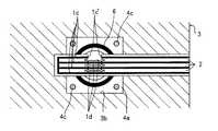
この実施例3は、図6〜図7に示す如く、前記複数の給電部1cが静電チャック機能面1′の外側領域に分散配置された屈曲可能な静電チャックフィルムを、これら給電部1cが台座3の側面3d又は裏面3aに沿って折り曲げ接着固定し、これら側面3d又は裏面3aに上記給電部1cと対向して形成された凹部3bを、開閉自在な密封構造にしてその内部に、切断された給電部1cの切断部分1c′を入れることで封止処理した構成が、前記図1〜図3に示した実施例1及び図4〜図5に示した実施例2とは異なり、それ以外の構成は図1〜図3に示した実施例1及び図4〜図5に示した実施例2と同じものである。 In this third embodiment, as shown in FIGS. 6 to 7, a bendable electrostatic chuck film in which the plurality of
図示例では、台座3が金属製であり、その凹部3b内に、前記絶縁性材料からなる絶縁体4として開閉自在なブロック4a,4bを配置すると共に、これらブロック4a,4b内に、切断された給電部1cの切断部分1c′を入れ、それを囲むように例えばOリングなどの環状シール材6で密封固定している。 In the illustrated example, the
更に、上記給電部1cを挟んでその両側とブロック4a,4bとの間にOリングなどの環状シール材6を一つずつ配置しているが、実験によれば、どちらか一方の環状シール材6のみでも封止できた。 Further, one
また、ブロック4a,4bは図示した形状に限定されず、他の形状に変更することも可能であり、これらブロック4a,4bをネジなどの締結部材4cで着脱自在に連結したが、他の種で連結することも可能である。 Further, the
従って、図6〜図7に示した実施例3は、上述した実施例1及び実施例2と同様な作用効果が得られ、更に加えて実施例1や実施例2で示した絶縁性接着剤などの被覆材5による給電部1cの切断部分1c′のモールド処理に比べて、簡便で且つ確実な封止処理を短時間に行えると共に封止部材の再使用が可能であるという利点がある。 Accordingly, in Example 3 shown in FIGS. 6 to 7, the same effects as those of Example 1 and Example 2 described above can be obtained, and in addition, the insulating adhesive shown in Example 1 and Example 2 can be obtained. Compared to the molding process of the
尚、本発明の静電チャック装置が基板貼り合わせ機に配備される場合を示したが、これに限定されず、この基板貼り合わせ機以外の基板組立装置や、基板を搬送する基板搬送装置に配備したり、LCDパネル用ガラス基板以外の基板を静電吸着し保持しても良い。
また、ワークWとして上下一対の基板を真空中で貼り合わせる基板貼り合わせ機を説明したが、これに限定されず、大気中で上下一対の基板を貼り合わせる基板貼り合わせ機でも良く、この場合でも、上述した真空貼り合わせ機と同じ作用効果が得られる。In addition, although the case where the electrostatic chuck device of the present invention is provided in the substrate bonding machine is shown, the present invention is not limited to this, and the substrate assembly apparatus other than the substrate bonding machine or the substrate transfer apparatus that transfers the substrate is used. Alternatively, a substrate other than the glass substrate for the LCD panel may be electrostatically adsorbed and held.
Moreover, although the board | substrate bonding machine which bonds a pair of upper and lower substrates in a vacuum as the workpiece | work W was demonstrated, it is not limited to this, The board | substrate bonding machine which bonds a pair of upper and lower board | substrates in air | atmosphere may be sufficient. The same effects as the above-described vacuum bonding machine can be obtained.
更に、前示実施例では、前記エリア1aが矩形状である場合を示したが、これに限定されず、扇型形状や同心円形状など図示例以外の形状であっても良い。この場合であっても前示した実施例1及び実施例2と同様な作用効果が得られる。
また、複数の給電部1c又は全ての給電部1cを集めて配置する場合を示したが、これに限定されず、全ての給電部1cを夫々適宜箇所に分散させて配置することも可能である。Furthermore, in the previous embodiment, the case where the
Moreover, although the case where the several electric
また更に、前記電極パターン1bを、ポリイミドやポリエーテルエーテルケトン(PEEK)などの絶縁性有機材料からなる誘電層2の間に挿入封止した場合を示したが、これに限定されず、電極パターン1bのワーク側表面のみに有機材料からなる誘電層2を積層して、裏面側には無機材料からなる誘電層2を積層したり、それ以外の絶縁性有機材料か又は他の材質からなる絶縁層を積層したり、また電極パターン1bのワーク側表面にも無機材料からなる誘電層2を積層しても良い。 Furthermore, the case where the
A 静電チャック装置 W ワーク
1 電極 1′ 静電チャック機能面
1a エリア 1b 電極パターン
1c 給電部 1c′ 切断部分
1d スリット 2 誘電層
3 台座 3a 裏面
3b 凹部 3c 表面
3d 側面 4 絶縁体
4a,4b ブロック 4c 締結部材
5 被覆材 6 環状シール材
11 保持板 11a 基板側表面A Electrostatic chuck
Claims (4)
Translated fromJapanese前記電極(1)をワーク(W)と平行な平面内で複数のエリア(1a)に分割し、これらエリア(1a)毎に独立する電極パターン(1b)を夫々設けると共に、各電極パターン(1b)への給電部(1c)をエリア(1a)毎に夫々設け、前記複数の給電部(1c)を、相互に接近させて平行に並べると共に、これら給電部(1c)に隣接する誘電層(2)部分に、該給電部(1c)に沿って平行なスリット(1d)を切欠形成し、各スリット(1d)から刃物で任意の給電部(1c)を選択的に切断処理可能にして、破壊したエリアに配置された電極パターン(1b)への給電を部分的に停止させたことを特徴とする静電チャック装置。In the electrostatic chuck device that electrostatically attracts the workpiece (W) by applying a voltage to the electrode (1) arranged in a plane facing the workpiece (W),
The electrode (1) is divided into a plurality of areas (1a) in a plane parallel to the work (W), and an independent electrode pattern (1b) is provided for each area (1a), and each electrode pattern (1b) is provided. feeding part of the) a (1c) respectively provided for each area (1a), said plurality of feeding parts to (1c), with arranged on aflat rowis brought closer to each other, a dielectric layer adjacent thereto feeding portion (1c) (2) to the portion, power feed portion notched to form aflat line slit (1d)along the (1c), selectively cleavable handle any feeding part with a knife from the slit (1d) (1c) An electrostatic chuck device characterized in that power supply to the electrode pattern (1b) arranged in the destroyed area is partially stopped.
Applications Claiming Priority (1)
| Application Number | Priority Date | Filing Date | Title |
|---|---|---|---|
| PCT/JP2005/008227WO2006117871A1 (en) | 2005-04-28 | 2005-04-28 | Electrostatic chuck apparatus |
Publications (2)
| Publication Number | Publication Date |
|---|---|
| JP3995706B2true JP3995706B2 (en) | 2007-10-24 |
| JPWO2006117871A1 JPWO2006117871A1 (en) | 2008-12-18 |
Family
ID=37307678
Family Applications (1)
| Application Number | Title | Priority Date | Filing Date |
|---|---|---|---|
| JP2006552399AExpired - Fee RelatedJP3995706B2 (en) | 2005-04-28 | 2005-04-28 | Electrostatic chuck device |
Country Status (5)
| Country | Link |
|---|---|
| JP (1) | JP3995706B2 (en) |
| KR (1) | KR100940549B1 (en) |
| CN (1) | CN100481369C (en) |
| TW (1) | TWI381479B (en) |
| WO (1) | WO2006117871A1 (en) |
Families Citing this family (32)
| Publication number | Priority date | Publication date | Assignee | Title |
|---|---|---|---|---|
| JP4976915B2 (en) | 2007-05-08 | 2012-07-18 | 新光電気工業株式会社 | Electrostatic chuck and method of manufacturing electrostatic chuck |
| JP5283707B2 (en)* | 2008-10-20 | 2013-09-04 | 株式会社クリエイティブ テクノロジー | Electrostatic chuck inspection method and electrostatic chuck apparatus |
| JP5328726B2 (en) | 2009-08-25 | 2013-10-30 | 三星ディスプレイ株式會社 | Thin film deposition apparatus and organic light emitting display device manufacturing method using the same |
| JP5677785B2 (en) | 2009-08-27 | 2015-02-25 | 三星ディスプレイ株式會社Samsung Display Co.,Ltd. | Thin film deposition apparatus and organic light emitting display device manufacturing method using the same |
| US8876975B2 (en) | 2009-10-19 | 2014-11-04 | Samsung Display Co., Ltd. | Thin film deposition apparatus |
| KR101084184B1 (en) | 2010-01-11 | 2011-11-17 | 삼성모바일디스플레이주식회사 | Thin film deposition apparatus |
| KR101174875B1 (en) | 2010-01-14 | 2012-08-17 | 삼성디스플레이 주식회사 | Apparatus for thin layer deposition, method for manufacturing of organic light emitting display apparatus using the same, and organic light emitting display apparatus manufactured by the method |
| KR101193186B1 (en) | 2010-02-01 | 2012-10-19 | 삼성디스플레이 주식회사 | Apparatus for thin layer deposition, method for manufacturing of organic light emitting display apparatus using the same, and organic light emitting display apparatus manufactured by the method |
| KR101156441B1 (en) | 2010-03-11 | 2012-06-18 | 삼성모바일디스플레이주식회사 | Apparatus for thin layer deposition |
| KR101202348B1 (en) | 2010-04-06 | 2012-11-16 | 삼성디스플레이 주식회사 | Apparatus for thin layer deposition and method for manufacturing of organic light emitting display apparatus using the same |
| US8894458B2 (en) | 2010-04-28 | 2014-11-25 | Samsung Display Co., Ltd. | Thin film deposition apparatus, method of manufacturing organic light-emitting display device by using the apparatus, and organic light-emitting display device manufactured by using the method |
| KR101223723B1 (en) | 2010-07-07 | 2013-01-18 | 삼성디스플레이 주식회사 | Apparatus for thin layer deposition, method for manufacturing of organic light emitting display apparatus using the same, and organic light emitting display apparatus manufactured by the method |
| KR101678056B1 (en) | 2010-09-16 | 2016-11-22 | 삼성디스플레이 주식회사 | Apparatus for thin layer deposition, method for manufacturing of organic light emitting display apparatus using the same, and organic light emitting display apparatus manufactured by the method |
| KR101723506B1 (en) | 2010-10-22 | 2017-04-19 | 삼성디스플레이 주식회사 | Apparatus for organic layer deposition and method for manufacturing of organic light emitting display apparatus using the same |
| KR101738531B1 (en) | 2010-10-22 | 2017-05-23 | 삼성디스플레이 주식회사 | Method for manufacturing of organic light emitting display apparatus, and organic light emitting display apparatus manufactured by the method |
| KR20120045865A (en) | 2010-11-01 | 2012-05-09 | 삼성모바일디스플레이주식회사 | Apparatus for organic layer deposition |
| KR20120065789A (en) | 2010-12-13 | 2012-06-21 | 삼성모바일디스플레이주식회사 | Apparatus for organic layer deposition |
| KR101760897B1 (en) | 2011-01-12 | 2017-07-25 | 삼성디스플레이 주식회사 | Deposition source and apparatus for organic layer deposition having the same |
| KR101923174B1 (en) | 2011-05-11 | 2018-11-29 | 삼성디스플레이 주식회사 | ESC, apparatus for thin layer deposition therewith, and method for manufacturing of organic light emitting display apparatus using the same |
| KR101852517B1 (en) | 2011-05-25 | 2018-04-27 | 삼성디스플레이 주식회사 | Apparatus for organic layer deposition and method for manufacturing of organic light emitting display apparatus using the same |
| KR101840654B1 (en) | 2011-05-25 | 2018-03-22 | 삼성디스플레이 주식회사 | Apparatus for organic layer deposition and method for manufacturing of organic light emitting display apparatus using the same |
| KR101857249B1 (en) | 2011-05-27 | 2018-05-14 | 삼성디스플레이 주식회사 | Patterning slit sheet assembly, apparatus for organic layer deposition, method for manufacturing organic light emitting display apparatus and organic light emitting display apparatus |
| KR20130004830A (en) | 2011-07-04 | 2013-01-14 | 삼성디스플레이 주식회사 | Apparatus for thin layer deposition and method for manufacturing of organic light emitting display apparatus using the same |
| KR101826068B1 (en) | 2011-07-04 | 2018-02-07 | 삼성디스플레이 주식회사 | Apparatus for thin layer deposition |
| KR20130069037A (en) | 2011-12-16 | 2013-06-26 | 삼성디스플레이 주식회사 | Apparatus for thin layer deposition, method for manufacturing of organic light emitting display apparatus using the same, and organic light emitting display apparatus |
| KR101959974B1 (en) | 2012-07-10 | 2019-07-16 | 삼성디스플레이 주식회사 | Apparatus for organic layer deposition, method for manufacturing of organic light emitting display apparatus using the same, and organic light emitting display apparatus manufactured by the method |
| US9496524B2 (en) | 2012-07-10 | 2016-11-15 | Samsung Display Co., Ltd. | Organic layer deposition apparatus, method of manufacturing organic light-emitting display apparatus using the same, and organic light-emitting display apparatus manufactured using the method |
| KR102013318B1 (en) | 2012-09-20 | 2019-08-23 | 삼성디스플레이 주식회사 | Apparatus for thin layer deposition, method for manufacturing of organic light emitting display apparatus using the same, and organic light emitting display apparatus |
| KR102108361B1 (en) | 2013-06-24 | 2020-05-11 | 삼성디스플레이 주식회사 | Apparatus for monitoring deposition rate, apparatus for organic layer deposition using the same, method for monitoring deposition rate, and method for manufacturing of organic light emitting display apparatus using the same |
| KR102162797B1 (en) | 2013-12-23 | 2020-10-08 | 삼성디스플레이 주식회사 | Method for manufacturing of organic light emitting display apparatus |
| KR102155584B1 (en)* | 2018-06-25 | 2020-09-14 | (주) 엔피홀딩스 | preventing diffused reflection type electro static chuck of laminating apparatus and laminating apparatus |
| KR102155583B1 (en)* | 2018-06-25 | 2020-09-14 | (주) 엔피홀딩스 | Back electrodes type electro static chuck of laminating apparatus, its manufacturing method and laminating apparatus |
Family Cites Families (6)
| Publication number | Priority date | Publication date | Assignee | Title |
|---|---|---|---|---|
| JPH05291562A (en)* | 1992-04-09 | 1993-11-05 | Toshiba Corp | Electrostatic chuck device |
| US5801915A (en)* | 1994-01-31 | 1998-09-01 | Applied Materials, Inc. | Electrostatic chuck having a unidirectionally conducting coupler layer |
| JP4493251B2 (en)* | 2001-12-04 | 2010-06-30 | Toto株式会社 | Electrostatic chuck module and substrate processing apparatus |
| KR100511854B1 (en)* | 2002-06-18 | 2005-09-02 | 아네르바 가부시키가이샤 | Electrostatic chuck device |
| CN100345274C (en)* | 2003-02-27 | 2007-10-24 | 株式会社日立高新技术 | Method of producing electrostatic suction cup |
| JP5004436B2 (en)* | 2005-05-23 | 2012-08-22 | 東京エレクトロン株式会社 | Electrostatic adsorption electrode and processing device |
- 2005
- 2005-04-28JPJP2006552399Apatent/JP3995706B2/ennot_activeExpired - Fee Related
- 2005-04-28CNCNB2005800496044Apatent/CN100481369C/ennot_activeExpired - Fee Related
- 2005-04-28WOPCT/JP2005/008227patent/WO2006117871A1/enactiveApplication Filing
- 2005-04-28KRKR1020077026621Apatent/KR100940549B1/ennot_activeExpired - Fee Related
- 2006
- 2006-01-20TWTW095102287Apatent/TWI381479B/ennot_activeIP Right Cessation
Also Published As
| Publication number | Publication date |
|---|---|
| JPWO2006117871A1 (en) | 2008-12-18 |
| CN100481369C (en) | 2009-04-22 |
| TW200644148A (en) | 2006-12-16 |
| WO2006117871A1 (en) | 2006-11-09 |
| KR100940549B1 (en) | 2010-02-10 |
| CN101167174A (en) | 2008-04-23 |
| TWI381479B (en) | 2013-01-01 |
| KR20080009285A (en) | 2008-01-28 |
Similar Documents
| Publication | Publication Date | Title |
|---|---|---|
| JP3995706B2 (en) | Electrostatic chuck device | |
| KR102860236B1 (en) | Edge ring, substrate support, plasma processing system and method of replacing edge ring | |
| KR100984748B1 (en) | Electrostatic chuck, assembled electrostatic adsorption device, glass substrate bonding device and assembled glass substrate bonding device | |
| CN100499073C (en) | Manufacturing method for semiconductor chips | |
| CN102473668B (en) | Electrostatic attracting structure and fabricating method therefor | |
| WO2010004915A1 (en) | Bipolar electrostatic chuck | |
| CN100505211C (en) | Method for manufacturing semiconductor chip and semiconductor wafer | |
| TWI423378B (en) | Electrostatic chuck | |
| TW200426953A (en) | Semiconductor manufacturing apparatus and method of manufacturing semiconductor device | |
| KR102176064B1 (en) | Electrostatic chuck mnufacturing method the electrostatic chuck | |
| JPWO2009013803A1 (en) | Electrostatic chuck surface potential control method | |
| JPWO2005109489A1 (en) | Work static elimination method and apparatus | |
| JP4053148B2 (en) | Plasma processing equipment | |
| CN103298615B (en) | Manufacturing method of laminated body | |
| TWI583555B (en) | Sheet Adhesive Device and Paste Method | |
| JP5785862B2 (en) | Electrostatic chuck and manufacturing method thereof, substrate temperature control fixing device | |
| CN114709158A (en) | Electrostatic chuck and substrate fixing device | |
| KR102733730B1 (en) | Processing method of a wafer | |
| KR20100090561A (en) | Electrostatic chuck having junction structure between different materals and fabrication method thereof | |
| JP4594358B2 (en) | Plasma processing equipment | |
| KR102184705B1 (en) | Method of repairing of electrostatic chuck | |
| JP2000183143A (en) | Electrostatic chuck | |
| JPH11251419A (en) | Electrostatic chuck for holding substrate and substrate holding method therefor | |
| JP2017220557A (en) | Electrostatic chuck sheet and wafer processing method | |
| KR102866417B1 (en) | Largearea transparent electrostatic chuck |
Legal Events
| Date | Code | Title | Description |
|---|---|---|---|
| TRDD | Decision of grant or rejection written | ||
| A01 | Written decision to grant a patent or to grant a registration (utility model) | Free format text:JAPANESE INTERMEDIATE CODE: A01 Effective date:20070724 | |
| A61 | First payment of annual fees (during grant procedure) | Free format text:JAPANESE INTERMEDIATE CODE: A61 Effective date:20070731 | |
| FPAY | Renewal fee payment (event date is renewal date of database) | Free format text:PAYMENT UNTIL: 20100810 Year of fee payment:3 | |
| R150 | Certificate of patent or registration of utility model | Free format text:JAPANESE INTERMEDIATE CODE: R150 | |
| FPAY | Renewal fee payment (event date is renewal date of database) | Free format text:PAYMENT UNTIL: 20100810 Year of fee payment:3 | |
| FPAY | Renewal fee payment (event date is renewal date of database) | Free format text:PAYMENT UNTIL: 20100810 Year of fee payment:3 | |
| FPAY | Renewal fee payment (event date is renewal date of database) | Free format text:PAYMENT UNTIL: 20130810 Year of fee payment:6 | |
| R250 | Receipt of annual fees | Free format text:JAPANESE INTERMEDIATE CODE: R250 | |
| R250 | Receipt of annual fees | Free format text:JAPANESE INTERMEDIATE CODE: R250 | |
| LAPS | Cancellation because of no payment of annual fees |