JP3994445B2 - Motion vector detection apparatus and motion vector detection method - Google Patents
Motion vector detection apparatus and motion vector detection methodDownload PDFInfo
- Publication number
- JP3994445B2 JP3994445B2JP34459895AJP34459895AJP3994445B2JP 3994445 B2JP3994445 B2JP 3994445B2JP 34459895 AJP34459895 AJP 34459895AJP 34459895 AJP34459895 AJP 34459895AJP 3994445 B2JP3994445 B2JP 3994445B2
- Authority
- JP
- Japan
- Prior art keywords
- search
- motion vector
- motion
- frame
- search range
- Prior art date
- Legal status (The legal status is an assumption and is not a legal conclusion. Google has not performed a legal analysis and makes no representation as to the accuracy of the status listed.)
- Expired - Fee Related
Links
- 239000013598vectorSubstances0.000titleclaimsdescription133
- 238000001514detection methodMethods0.000titleclaimsdescription129
- 230000007274generation of a signal involved in cell-cell signalingEffects0.000claimsdescription4
- 238000010586diagramMethods0.000description23
- 238000007689inspectionMethods0.000description10
- 238000000034methodMethods0.000description10
- 238000003384imaging methodMethods0.000description4
- 230000015556catabolic processEffects0.000description2
- 238000006731degradation reactionMethods0.000description2
- 230000006870functionEffects0.000description2
- 230000000694effectsEffects0.000description1
- 238000013139quantizationMethods0.000description1
- 230000009466transformationEffects0.000description1
- 230000000007visual effectEffects0.000description1
Images


Classifications
- H—ELECTRICITY
- H04—ELECTRIC COMMUNICATION TECHNIQUE
- H04N—PICTORIAL COMMUNICATION, e.g. TELEVISION
- H04N19/00—Methods or arrangements for coding, decoding, compressing or decompressing digital video signals
- H04N19/50—Methods or arrangements for coding, decoding, compressing or decompressing digital video signals using predictive coding
- H04N19/503—Methods or arrangements for coding, decoding, compressing or decompressing digital video signals using predictive coding involving temporal prediction
- H04N19/51—Motion estimation or motion compensation
- H04N19/56—Motion estimation with initialisation of the vector search, e.g. estimating a good candidate to initiate a search
Landscapes
- Engineering & Computer Science (AREA)
- Multimedia (AREA)
- Signal Processing (AREA)
- Compression Or Coding Systems Of Tv Signals (AREA)
- Compression, Expansion, Code Conversion, And Decoders (AREA)
Description
Translated fromJapanese【0001】
【発明の属する技術分野】
本発明は、例えばMPEG(Movimg Picture Image Coding Experts Group)に準拠した画像符号化装置、特に動きベクトルの検出技術に関する。
【0002】
【従来の技術】
MPEG方式は、DCT(Discrete Cosine Transform)と動き補償予測と可変長符号化とを組み合わせて画像データの圧縮を行う符号化方式である。
【0003】
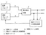
図13にMPEG方式に準拠した画像符号化装置の構成を示す。この図において、入力端子T1に画像データが供給される。この画像データは動きベクトル検出回路21と減算回路22とに入力される。動きベクトル検出回路21は、入力された画像データを用いて現フレームと参照フレーム(例えば前フレーム)との動きベクトルを求め、動き補償回路23へ与える。
【0004】
参照フレームの画像データはフレームメモリ24内にも格納されている。この画像データは動き補償回路23へ供給される。動き補償回路23では、動きベクトル検出回路21から送られてくる動きベクトルを用いて、フレームメモリ24から送られてくる画像データの動き補償を行う。動き補償回路23の出力は減算回路22と加算回路25へ送られる。
【0005】
減算回路22では、入力端子T1から供給される現フレームの画像データと、動き補償回路23から供給される動き補償された参照フレームの画像データとを減算して予測誤差データを求め、DCT回路26へ供給する。DCT回路26は、この予測誤差データをDCT処理して量子化器27へ送る。量子化器27はDCT回路26の出力を量子化し、可変長符号化回路28へ送る。可変長符号化回路28は量子化器27の出力を可変長符号化し、出力端子T2から出力する。
【0006】
量子化器27の出力は逆量子化器29にも供給される。そして、ここで逆量子化処理を受け、その出力は逆DCT回路30において逆DCT処理を受けて、元の予測誤差データに戻され、加算回路25へ与えられる。
【0007】
加算回路25では、この予測誤差データを動き補償回路23の出力データに加算して現フレームの画像データを求める。求められた画像データは次の参照フレームの画像データとしてフレームメモリ24に格納される。
【0008】
このような画像符号化装置における動きベクトル検出の方法としてはブロックマッチング法が知られている。ブロックマッチング法は、画面を小さな矩形領域(ブロック)に分割して、ブロック毎に動きを検出する。ブロックのサイズとしては、横8画素×縦8画素(以下8×8と略す)、16×16等がある。次に図14を参照しながらブロックマッチング法について説明する。
【0009】
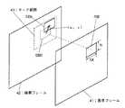
図14において、基準フレーム41内にM×Nの基準ブロックRBを設定する。また、検索フレーム42内に基準ブロックRBと同じサイズの検査ブロックSBを設定する。検査ブロックSBは、基準ブロックRBと同じ位置を中心に±m×±nの所定のサーチ範囲43内を巡って移動される。そして、基準ブロックRBと検査ブロックSBとの一致度を計算し、最も一致度の高い検査ブロックをマッチングブロックとし、このマッチングブロックから動きベクトルを求める。
【0010】
すなわち、基準ブロックRBと同じ位置にある検査ブロックSB0から(u,v)シフトした位置にある検査ブロックSBkの一致度が最も高い場合には、その基準ブロックRBの動きベクトルを(u,v)とする。このとき、基準ブロックRBと検査ブロックSBの同じ位置の画素毎の絶対値差分の総和や画素毎の差分の2乗の総和等が最小になる検査ブロックを最も一致度の高い検査ブロックとする。
【0011】
MPEG方式においては動画像の1シーケンスを複数のフレーム(ピクチャー)からなるGOP(Group of Picture)に分割して符号化を行う。GOPはフレーム内符号化画像(Iピクチャー)と、既に符号化された時間的に前のフレームから予測するフレーム間符号化画像(Pピクチャー)と、既に符号化された時間的に前後の2フレームから予測するフレーム間符号化画像(Bピクチャー)とから構成される。
【0012】
例えば図15においては、始めにPピクチャーであるP3を基準フレームとし、IピクチャーであるI0を検索フレームとして動き検出を行う。次にBピクチャーであるB1を基準フレームとし、I0とP3を検索フレームとして両方向の動き検出を行う。次にBピクチャーであるB2を基準フレームとし、I0とP3を検索フレームとして両方向の動き検出を行う。
【0013】
図16に示すように、一般に動き検出に必要なサーチ範囲は基準フレームと検索フレームとのフレーム間隔に比例して増大することが望ましい。ここでは、ブロックサイズが16×16の場合について説明を行なう。例えば1フレーム離れた場合にサーチ範囲が水平方向、垂直方向共に±16とすると、2フレーム離れた場合には±32、3フレーム離れた場合には±48のサーチ範囲とすることが望ましい。
【0014】
しかしながら、このようにフレーム間隔に比例してサーチ範囲を広げた場合には、動き検出に必要ハード量もそれぞれ1フレーム離れた場合の4倍、9倍と増加してしまう。つまり、P3を基準フレームとし、I0を検索フレームとした動き検出のような3フレーム間離れた動き検出を行なうためには非常に大きなハード量が必要となる。
【0015】
そこで、ハード量を増加させずにサーチ範囲を拡大する方法としてテレスコピックサーチが知られている。これは、サーチする範囲は常に±16としながらも、基準ブロック毎にサーチ範囲の中心にオフセットを持たせることにより大きなサーチ範囲をカバーするものである。次に図17を参照しながらテレスコピックサーチについて説明する。
【0016】
図17に示すように、例えば基準フレームに対して3フレーム離れた検索フレーム3においてサーチを行なう場合には、始めに1フレーム離れた検索フレーム1において±16のサーチ範囲で、基準ブロックにおける動きベクトルMV1を求める。次に2フレーム離れた検索フレーム2において、MV1をサーチ範囲の中心として±16のサーチ範囲でサーチを行ない動きベクトルMV2を求める。このとき、基準フレーム内の基準ブロックから見たサーチ範囲は±32となる。最後に3フレーム離れた検索フレーム3において、MV2をサーチ範囲の中心として±16のサーチ範囲でサーチを行ない動きベクトルMV3を求める。このようにして最後に3フレーム離れた動きベクトルがサーチ範囲±48に対して求まる。この場合に必要なハード量は±16のサーチ範囲をカバーするハード量のみでよい。
【0017】
【発明が解決しようとする課題】
図18にサーチデータの転送量の比較をサーチ範囲が固定の場合とテレスコピックサーチの場合について示す。
【0018】
サーチ範囲を固定した場合には、この図の(a)に示すように、水平方向に隣接した基準ブロック例えばRB0とRB1では32×48はサーチ範囲が重なるため、サーチ範囲が重ならない16×48のデータのみを新たに転送すれば良い。
【0019】
これに対して、テレスコピックサーチの場合には、検索フレーム2及び3においては、基準ブロック毎にサーチ範囲が異なる為に、各基準ブロック毎に±16のサーチ範囲分(48×48)を256(=16×16)クロックで転送する必要がある。
【0020】
つまり、±16のサーチ範囲でテレスコピックサーチを行なうためには、(48×48)/(16×48)=3倍のサーチデータの転送レートを必要とすることになる。この値はサーチ範囲が増大するとさらに大きくなり、例えば±32の場合にはテレスコピックサーチで必要とする転送レートは、(80×80)/(80×16)=5倍となってしまい、データの転送が非常に困難となる。画素データ8ビット、画素クロックを13.5MHzとすると、この場合には、
(80×80/256)×13.5MHz×1byte=337.5Mバイト/secもの転送レートが必要となる。この大きな転送レートはハードを実現する上で大きな障害となる。
【0021】
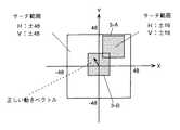
また、従来のテレスコピックサーチにおいては、図19に示すように、斜め右上へ大きく動いたと判断して±16のサーチ範囲を設定した後、正しい動きベクトルが動きの小さいベクトルであった場合には、±16のサーチ範囲内で正しい動きベクトルは検出できない。この場合、画像の動きが小さいので視覚的に大きな画質劣化となる。
【0022】
このように、従来のテレスコピックサーチでは、検索データを転送するために非常に大きなデータ転送レートが必要であるという欠点を持っていた。また、大きく動いたと判断を行ない、正しい動きベクトルが動きの小さいベクトルであった場合には、正しい動きベクトルは検出できず、しかも画像の動きが小さいので、視覚的に大きな画質劣化となる欠点を持っていた。
【0023】
本発明はこのような問題点に鑑みてなされたものであって、検索データの転送レートを増大させることなくサーチ範囲を拡大できる動きベクトル検出装置及び動きベクトル検出方法を提供するものである。
【0024】
【課題を解決するための手段】
前記課題を解決するために、本発明は、基準フレームの画像データと前記基準フレームからNフレーム離れた検索フレームの画像データに基づき動きベクトルを検出する動きベクトル検出装置において、前記基準フレームの基準ブロックの画像データと前記基準フレームからMフレーム(N、MはN>M≧1を満たす整数)離れた前記検索フレームと異なる他の検索フレームの検索ブロックの画像データとを演算することにより基準ブロック単位で動きベクトルを検出する動き検出手段と、前記動き検出手段が検出した水平方向又は垂直方向に連続する複数の前記基準ブロック単位の動きベクトルに基づき、検索データ読み出し制御信号を生成する制御信号生成手段と、前記制御信号生成手段が生成した検索データ読み出し制御信号に基づき、前記検索フレームにおける水平方向又は垂直方向に連続する複数の基準ブロックの単位でサーチ範囲を設定する設定手段とを有することを特徴とする。
【0025】
また、本発明は、基準フレームの画像データと前記基準フレームからNフレーム離れた検索フレームの画像データに基づき動きベクトルを検出する動きベクトル検出方法であって、前記基準フレームの基準ブロックの画像データと前記基準フレームからMフレーム(N、MはN>M≧1を満たす整数)離れた前記検索フレームと異なる他の検索フレームの検索ブロックの画像データとを演算することにより基準ブロック単位で動きベクトルを検出し、検出した水平方向又は垂直方向に連続する複数の前記基準フレームの前記基準ブロックに対応する動きベクトルの分布に基づき、検索データ読み出し制御信号を生成し、生成した前記検索データ読み出し制御信号に基づき、前記検索フレームにおける水平方向又は垂直方向に連続する複数個の基準ブロックの単位でサーチ範囲を設定することを特徴とする。
【0030】
【発明の実施の形態】
以下本発明の実施の形態について図面を参照しながら、
〔1〕動きベクトル検出回路の第1の実施の形態
〔2〕動きベクトル検出回路の第2の実施の形態
〔3〕動きベクトル検出回路の第3の実施の形態
〔4〕動きベクトル検出回路の第4の実施の形態
〔5〕本発明に係る動きベクトル検出回路を備えた撮像記録装置
の順序で詳細に説明する。
【0031】
〔1〕動きベクトル検出回路の第1の実施の形態
図1は本発明を適用した動きベクトル検出回路の第1の実施の形態を示すブロック図である。この動きベクトル検出回路は、基準フレームメモリー1と、検索フレームメモリー2と、動き検出回路3と、動きベクトル分布検出回路4とから構成されている。
【0032】
基準フレームメモリー1は基準フレームの画像を格納する。検索フレームメモリー2は、検索フレームメモリーの画像を格納し、動きベクトル分布検出回路4から送られる検索データ読み出し制御信号cにしたがって、検査ブロックのサーチ範囲を設定する。
【0033】
動き検出回路3は、基準フレームメモリー1から転送されてくる基準ブロックの画像データaと検索フレームメモリー2から転送されてくる検査ブロックの画像データbとからその基準ブロックの動きベクトルdを求める。この動きベクトルdは、従来例と同じくブロックマッチング法により求める。すなわち、基準ブロックと検査ブロックの同じ位置の画素毎の絶対値差分の総和や画素毎の差分の2乗の総和(以下残差という)が最小になる検査ブロックの位置から動きベクトルdを求める。動き検出回路3は求めた動きベクトルdをそのときの残差eと共に出力する。
【0034】
動きベクトル分布検出回路4は、動き検出回路3から送られてくる動きベクトルdと残差eとを基に検索データ読み出し制御信号cを生成し、検索フレームメモリー2へ供給する。
【0035】
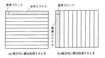
図2は前述した動き検出回路3のサーチ範囲を説明する図である。この図の(a)は、基準ブロックを画像の横方向へ左端から右端へ移動させる操作を上端から下端へと進める場合であり、(b)は基準ブロックを画像の縦方向へ上端から下端へ移動させる操作を左端から右端へと進める場合である。以下の説明では、横方向の連続した基準ブロックを水平スライス、縦方向の連続した基準ブロックを垂直スライスという。
【0036】
本発明においては、基準フレームと参照フレームとの動きベクトルの分布を水平スライス又は垂直スライス毎に求め、その分布状態に応じて離れたフレームにおけるサーチ範囲を設定する。以下の説明では、図2(a)に示した水平スライス毎に動きベクトルの分布を求める場合について説明する。
【0037】
図2(a)において、画像のサイズを720×576とし、基準ブロックのサイズを16×16とすると、576/16=36個の水平スライスが形成される。また、1水平スライス当り720/16=45個の基準ブロックとなる。ここでは、各水平スライス毎に基準ブロックと1フレーム前の検査ブロックとの動きベクトルを検出し、その分布を求める。そして、その分布状態に応じて2フレーム以上離れた参照フレームにおけるその水平スライスのサーチ範囲を設定する。
【0038】
例えば、ある水平スライスにおける45個の動きベクトルの内、上を向いている動きベクトルの数が所定のしきい値を超えている場合には、上方向にサーチ範囲を設定する。
【0039】
図18を参照しながら説明したように、テレスコピックサーチでは、検索フレーム2及び3においては、基準ブロック毎にサーチ範囲が異なる為に、各基準ブロック毎に±16のサーチ範囲分(48×48)を256(=16×16)クロックで転送する必要がある。これに対して、本実施の形態では、水平スライス毎にサーチ範囲を設定しているため、水平スライス内では水平方向に隣接した基準ブロック同士でサーチ範囲を共有するので、図18(a)に示した、通常のサーチ範囲を固定した場合と検索画像データの読み出しレートは同一である。
【0040】
〔2〕動きベクトル検出回路の第2の実施の形態
図3は本発明を適用した動きベクトル検出回路の第2の実施の形態を示すブロック図である。ここで、図1と対応する部分には同一の番号が付してある。
【0041】
この動きベクトル検出回路は、第1の動き検出回路3−Aと第2の動き検出回路3−Bを備えている。また、第1の動き検出回路3−Aが出力する動きベクトルd1と残差e1、又は第2の動き検出回路3−Bが出力する動きベクトルd2と残差e2から、スライス毎の動きベクトルの分布を検出し、検索データ読み出し制御信号cを生成する動きベクトル分布検出回路4’を備えている。さらに、第1の動き検出回路3−Aが出力する動きベクトルd1と残差e1、及び第2の動き検出回路3−Bが出力する動きベクトルd2と残差e2から、最終動きベクトルfを求める比較回路5を備えている。
【0042】
第1の動き検出回路3−Aと第2の動き検出回路3−Bとは互いに異なるサーチ範囲において動き検出を行うことができる。それぞれの動き検出回路のサーチ範囲は水平垂直方向共に±16とする。
【0043】
サーチ範囲を固定とする場合には、一般に水平方向に大きく動く画像が多いことから、水平方向のサーチ範囲が垂直方向のサーチ範囲よりも大きくなるように図4(1)のように設定する。この図において、Y軸の左側に3−Aと指示した範囲は第1の動き検出回路3−Aのサーチ範囲であり、Y軸の右側に3−Bと指示した範囲は第2の動き検出回路3−Bのサーチ範囲である。この場合、第1の動き検出回路3−Aと第2の動き検出回路3−Bのトータルのサーチ範囲は、水平±32、垂直±16となり、サーチ範囲の中心に対応する基準ベクトルは、(X,Y)=(0,0)となる。
【0044】
一方、水平スライス単位でサーチ範囲を可変にする場合には、第1の動き検出回路3−Aのサーチ範囲を固定し、第2の動き検出回路3−Bのサーチ範囲を変化させる。これにより、図4(2)に示すように、サーチ範囲を水平±48、垂直±48に拡大することが可能となる(詳細は後述する)。
【0045】
以下図5を参照しながら図3に示した動きベクトル検出回路の動き検出動作を説明する。図5において、3フレーム離れたP3からI0への動き検出を行なう前に、1フレーム離れたB1からI0への動き検出を第1の動き検出回路3−Aを用いて行ない、その残差e1及び動きベクトルd1の結果を動きベクトル分布検出回路4’に保存する。また、2フレーム離れたB−2からI0への動き検出を第2の動き検出回路3−Bを用いて行なう。このときのサーチ範囲は、第1の動き検出回路3−A、第2の動き検出回路3−B共に水平±16、垂直±16であり、サーチ範囲の中心に対応する基準ベクトルは、(X,Y)=(0,0)である。
【0046】
次に第1の動き検出回路3−Aでは、2フレーム離れたB2からI0への動き検出を行ない、第2の動き検出回路3−Bでは、1フレーム離れたB−1からI0への動き検出を行なう。
【0047】
そして、次に3フレーム離れたP3からI0への動き検出を、先に求めて動きベクトル分布検出回路4’に保存しておいたB1からI0への動き検出の結果を用いて水平スライス毎にサーチ範囲を変えて行なう。
【0048】
以上の説明では、1フレーム離れた画像の動き検出の結果を用いて3フレーム離れた画像の動き検出をスライス毎にサーチ範囲を変えて行っているが、一般的には、Mフレーム又はフィールド離れた画像の動き検出の結果を用いてNフレーム又はフィールド(N、MはN>M≧1を満たす整数)離れた画像の動き検出をスライス毎にサーチ範囲を変えて行なう。
【0049】
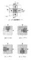
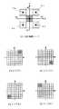
図6〜図8は、図3に示した動きベクトル検出回路のサーチ範囲のモードを示す図であり、図9はその動きベクトル検出回路がP3からI0への動き検出を行なう際の動作を示すフローチャートである。
【0050】
図9に示すように、始めにステップS1においてフレーム間の動き検出を行なう。これは図5を参照しながら既に説明した、B1からI0への1フレーム間の動き検出を行なうことに相当する。
【0051】
次にステップS2において、1フレーム間の動き検出に対する動きベクトル分布を1スライス分作成する。具体的には、水平±16、垂直±16(32×32)の動きベクトルのサーチ範囲を4×4の大きさの小ブロックに分割し、その小ブロック毎に検出された動きベクトルの数をカウントする。このとき、ある閾値よりも残差の大きい動きベクトルは、信頼性が低いのでカウントしない。
【0052】
次にステップS3において、静止モード(ノーマルモード)かどうかの判定を行なう。Count(エリア1)が閾値Th1以上であればノーマルモードと判定する。ここで、Count(指定領域)という関数は、指定領域に含まれる動きベクトル数の合計を返す関数である。
【0053】
エリア1は、図6(2)の中心部に網掛けを施した±4のエリアである。このエリアは動きの小さい領域に相当する。すなわち、ステップ1で作成した1スライスの動きベクトルの大多数が動きの小さい動きベクトルである場合にはノーマルモードと判定する。
【0054】
ステップS3においてノーマルモードと判定した場合には、次にステップS4においてノーマルモードに設定し、ステップS10においてノーマルモードに応じたサーチ範囲を設定する。
【0055】
図6(1)は静止モードのサーチ範囲を示す。このサーチ範囲は、図4(1)に示したサーチ範囲固定の場合と同一である。そして、サーチ範囲の中心ベクトルは、それぞれSMV1=(mvx1,mvy1)=(−16,0)、SMV2=(mvx2,mvy2)=(16,0)である。
【0056】
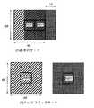
以上ステップS3で静止モードであると判定した場合について説明した。ステップS3で静止モードでないと判定した場合には、次にステップS5で水平,垂直移動モードであるかどうかを判定する。この判定は、図7(2)〜(5)に示すエリア2−1〜2−4毎にそのエリアに含まれる動きベクトルの合計が所定の閾値Th2以上であるかどうかを調べることにより行う。
【0057】
そして、エリア2−1に含まれる動きベクトルの合計がTh2以上であればモード2−1、エリア2−2に含まれる動きベクトルの合計がTh2以上であればモード2−2、エリア2−3に含まれる動きベクトルの合計がTh2以上であればモード2−3、エリア2−4に含まれる動きベクトルの合計がTh2以上であればモード2−4と判定する。
【0058】
ステップS5において水平,垂直移動モード、すなわちモード2−1〜2−4のいずれかであると判定した場合には、次にステップS6においてそのモードに設定し、ステップS10においてそのモードに応じたサーチ範囲を設定する。
【0059】
図7(1)にモード2−1〜2−4のサーチ範囲を示す。この図において、中心部の±16のサーチ範囲は第1の動き検出回路3−Aのサーチ範囲であり、それに隣接する2−1〜2−4はそれぞれモード2−1〜2−4における第2の動き検出回路3−Bのサーチ範囲である。それぞれのサーチ範囲の中心ベクトルは以下のとおりである。
【0060】
モード2−1・・・SMV1=(0,0)、SMV2=(0,16)
モード2−2・・・SMV1=(0,0)、SMV2=(16,0)
モード2−3・・・SMV1=(0,0)、SMV2=(0,−16)
モード2−4・・・SMV1=(0,0)、SMV2=(−16,0)
【0061】
ステップS5で水平,垂直移動モードでないと判定した場合には、次にステップS7で斜め移動モードであるかどうかの判定を行なう。この判定は、図8(2)〜(5)に示すエリア3−1〜3−4毎にそのエリアに含まれる動きベクトルの合計が所定の閾値Th3以上であるかどうかを調べることにより行う。
【0062】
そして、エリア3−1に含まれる動きベクトルの合計がTh3以上であればモード3−1、エリア3−2に含まれる動きベクトルの合計がTh3以上であればモード3−2、エリア3−3に含まれる動きベクトルの合計がTh3以上であればモード3−3、エリア3−4に含まれる動きベクトルの合計がTh3以上であればモード3−4と判定する。
【0063】
ステップS7において斜め移動モード、すなわちモード3−1〜3−4のいずれかであると判定した場合には、次にステップS8においてそのモードに設定し、ステップS10においてそのモードに応じたサーチ範囲を設定する。
【0064】
図8(1)にモード3−1〜3−4のサーチ範囲を示す。この図において、中心部の±16のサーチ範囲は第1の動き検出回路3−Aのサーチ範囲であり、その外側の3−1〜3−4はそれぞれモード3−1〜3−4における第2の動き検出回路3−Bのサーチ範囲である。それぞれのサーチ範囲の中心ベクトルは以下のとおりである。
【0065】
モード3−1・・・SMV1=(0,0)、SMV2=(16,16)
モード3−2・・・SMV1=(0,0)、SMV2=(16,−16)
モード3−3・・・SMV1=(0,0)、SMV2=(−16,−16)
モード3−4・・・SMV1=(0,0)、SMV2=(−16,16)
【0066】
ステップS7で斜め移動モードでないと判定した場合、つまり静止モード、水平、垂直モード、斜め移動モードのいずれのモードにも判定されなかった場合には、ステップS9でノーマルモードに設定する。そして、ステップS10においてノーマルモードに応じたサーチ範囲を設定する。
【0067】
ステップS10においてサーチ範囲を設定したら、次にステップS11において、3フレーム離れたP3からI0への動き検出を対応する1水平スライス分、行なう。第1の動き検出回路3−Aと第2の動き検出回路3−Bからの結果は、図3の比較回路5へ入力され、残差の小さい動きベクトルが最終的に動きベクトルfとして出力される。
【0068】
次にステップS12において、1フレーム分の処理を終えているかをどうかを判定し、終えていなければ、ステップS2へ戻り処理を繰り返す。1フレーム分の処理を終えていれば処理を終える。
【0069】
このように、本実施の形態によれば常に(0,0)の周辺(ここでは、水平、垂直共に±16)をカバーしながらサーチ範囲を可変にする。したがって、動きのモードの判定に誤りがあった場合や、スライスの一部の基準ブロックの動きが他の基準ブロックと動く方向が異なる場合についても、画質劣化の目につきやすい、動きの小さなものに対しては対処が可能となる。
【0070】
この実施の形態では、3種類の動きのモード(静止、水平,垂直移動、斜め移動)を持っているが、より多くの細かいモードを持つように構成してもよい。また、この実施の形態では、1フレーム間のベクトル分布により3フレーム間の動きベクトルを求める実施例を示したが、実際には、Mフレーム又はフィールド間の動きベクトルよりNフレーム又はフィールド間(N、MはN>M≧1を満たす整数)の動きベクトルを求めることが可能である。
【0071】
〔3〕動きベクトル検出回路の第3の実施の形態
図10に本発明を適用した動きベクトル検出回路の第3の実施の形態におけるサーチ範囲を示す。装置の構成はほぼ図3と同じである。ただし、本実施の形態では第1の動き検出回路3−Aは水平、垂直共±16のサーチ範囲で従来のテレスコピックサーチを行い、第2の動き検出回路3−Bは常に(0,0)を中心として水平、垂直共±16のサーチ範囲でサーチ範囲固定のサーチを行うので、図3の動きベクトル分布検出回路4’の代わりに、従来のテレスコピックサーチとサーチ範囲固定のサーチに必要な検索データ読み出し制御信号の作成を行う回路を設ける。
【0072】
このように構成すれば、大きく動いたと判断を行ない、正しい動きベクトルが動きの小さいベクトルであった場合にも、第2の動き検出回路3−Bにより正しい動きベクトルの検出が可能となる。
【0073】
〔4〕動きベクトル検出回路の第4の実施の形態
図11は本発明を適用した動きベクトル検出回路の第4の実施の形態を示すブロック図である。ここで、図1と対応する部分には同一の番号が付してある。この画像符号化装置の構成は基本的には図1に示した動きベクトル検出回路と同じである。ただし、この装置では、動きベクトル分布検出回路4”は動き検出回路3が出力する動きベクトルdと残差eとを用いるのではなく、外部から動き信号gを受け取る。この動き信号gは、例えばビデオカメラの手ブレ補正に用いる動きベクトル検出回路や角速度センサーから受け取る。この場合、動き検出回路3におけるサーチ範囲はスライス毎に可変ではなく、全スライスについて同じになる。
【0074】
〔5〕本発明に係る動きベクトル検出回路を備えた撮像記録装置
図12に本発明に係る動きベクトル検出回路を備えた撮像記録装置を示す。この図において、符号化回路12は基本的に図13のように構成されているが、その内部の動きベクトル検出回路はこれまで説明した図1、図3、又は図11のように構成されている。この符号化回路12には、カメラ部11からビデオ信号と動き信号gとが供給される。動き信号gは、図11において説明したものである。そして、符号化回路12における動きベクトル検出回路を図1又は図3のように構成した場合には、動きベクトル分布検出回路は、動き検出回路から送られてくる動きベクトルと残差、及びカメラ部11から送られてくる動き信号gの双方を用いて、検索フレームメモリーの検索データ読み出し制御信号を生成する。
【0075】
符号化回路12により符号化されたビデオ信号は変調回路13において所定の記録変調処理を受け、記録デバイス14に記録される。記録デバイスとしては、ハードディスク、光磁気ディスク、DVD(Digital Video Disk)−RAM(Random Access Memory)等を使用する。
【0076】
なお、本発明は前記実施の形態に限定されるものではなく、本発明の趣旨に基づいて種々の変形が可能である。例えば、サーチ範囲を可変とする単位を水平スライスの右半分、左半分のようにしてもよい。この場合には、水平スライスの中心のサーチ範囲の変化する部分でわずかに検索データの読み出しレートの増加が起こるが、水平ブランキング期間で時間的に吸収可能である。このようにサーチ範囲を可変とする単位を小さくすることによりより、検索データの読み出しレートは増加するものの細かい動きに対応可能となる。また、本発明は、フィールド間の動きを検出する場合にも適用することができる。
【0077】
【発明の効果】
以上詳細に説明したように、本発明によれば、検索データの転送レートを増加させることなく、動きベクトルのサーチ範囲を拡大することができる。
【0078】
また、常に動きの小さい部分をカバーしながらサーチ範囲を可変にすることにより、サーチ範囲のモードの判定に誤りがあった場合や、スライスの一部の基準ブロックの動きが他の基準ブロックと動く方向が異なる場合についても画質劣化の目につきやすい、動きの小さなものに対しては対処が可能となる。
【図面の簡単な説明】
【図1】本発明を適用した動きベクトル検出装置の第1の実施の形態を示すブロック図である。
【図2】図1における動き検出回路のサーチ範囲を説明する図である。
【図3】本発明を適用した動きベクトル検出回路の第2の実施の形態を示すブロック図である。
【図4】図3における動き検出回路のサーチ範囲を説明する図である。
【図5】図3の動きベクトル検出回路の動き検出の例を示す図である。
【図6】図3における動き検出回路の静止モードを示す図である。
【図7】図3における動き検出回路の水平,垂直移動モードを示す図である。
【図8】図3における動き検出回路の斜め移動モードを示す図である。
【図9】図3の動きベクトル検出回路の動作を示すフローチャートである。
【図10】本発明を適用した動きベクトル検出装置の第3の実施の形態におけるサーチ範囲を示す図である。
【図11】本発明を適用した動きベクトル検出回路の第4の実施の形態を示すブロック図である。
【図12】本発明に係る動きベクトル検出回路を備えた撮像記録装置の構成を示すブロック図である。
【図13】MPEG方式に準拠した画像符号化装置の構成を示すブロック図である。
【図14】ブロックマッチング法について説明するための図である。
【図15】MPEGにおける動き検出の例を示す図である。
【図16】フレーム間隔と望ましいサーチ範囲との関係を示す図である。
【図17】従来のテレスコピックサーチを示す図である。
【図18】通常のサーチとテレスコピックサーチのデータ転送量を比較する図である。
【図19】テレスコピックサーチにおいて正しい動きベクトルが検出できない様子を示す図である。
【符号の説明】
1…基準フレームメモリー、2…検索フレームメモリー、3,3−A,3−B…動き検出回路、4,4’,4”…動きベクトル分布検出回路[0001]
BACKGROUND OF THE INVENTION
The present invention relates to an image encoding apparatus compliant with, for example, MPEG (Moving Picture Image Coding Experts Group), and more particularly to a motion vector detection technique.
[0002]
[Prior art]
The MPEG system is an encoding system that compresses image data by combining DCT (Discrete Cosine Transform), motion compensation prediction, and variable length encoding.
[0003]
FIG. 13 shows the configuration of an image encoding device compliant with the MPEG system. In this figure, image data is supplied to the input terminal T1. This image data is input to the motion
[0004]
The image data of the reference frame is also stored in the
[0005]
The subtraction circuit 22 subtracts the current frame image data supplied from the input terminal T1 and the motion compensated reference frame image data supplied from the
[0006]
The output of the
[0007]
The
[0008]
A block matching method is known as a motion vector detection method in such an image encoding device. In the block matching method, a screen is divided into small rectangular areas (blocks), and motion is detected for each block. The block size includes 8 horizontal pixels × 8 vertical pixels (hereinafter abbreviated as 8 × 8), 16 × 16, and the like. Next, the block matching method will be described with reference to FIG.
[0009]
In FIG. 14, an M × N reference block RB is set in the reference frame 41. In addition, a test block SB having the same size as the reference block RB is set in the search frame 42. The inspection block SB is moved around a predetermined search range 43 of ± m × ± n around the same position as the reference block RB. Then, the degree of coincidence between the reference block RB and the inspection block SB is calculated, and the inspection block having the highest degree of coincidence is set as a matching block, and a motion vector is obtained from the matching block.
[0010]
That is, when the matching degree of the inspection block SBk at the position shifted (u, v) from the inspection block SB0 at the same position as the reference block RB is the highest, the motion vector of the reference block RB is (u, v). And At this time, the inspection block having the smallest sum of absolute value differences for each pixel at the same position in the reference block RB and the inspection block SB, the sum of squares of the differences for each pixel, and the like is set as the inspection block with the highest degree of coincidence.
[0011]
In the MPEG system, one sequence of moving images is divided into GOPs (Group of Pictures) made up of a plurality of frames (pictures) for encoding. The GOP includes an intra-frame encoded image (I picture), an inter-frame encoded image (P picture) predicted from an already encoded temporally previous frame, and two frames that are already encoded temporally. And an inter-frame encoded image (B picture) predicted from the image.
[0012]
For example, in FIG. 15, first, motion detection is performed using P3 which is a P picture as a reference frame and I0 which is an I picture as a search frame. Next, motion detection in both directions is performed using B1, which is a B picture, as a reference frame and I0 and P3 as search frames. Next, motion detection in both directions is performed using B2, which is a B picture, as a reference frame and I0 and P3 as search frames.
[0013]
As shown in FIG. 16, it is generally desirable that the search range necessary for motion detection increases in proportion to the frame interval between the reference frame and the search frame. Here, a case where the block size is 16 × 16 will be described. For example, if the search range is ± 16 in both the horizontal and vertical directions when separated by one frame, it is desirable that the search range be ± 32 when separated by 2 frames and ± 48 when separated by 3 frames.
[0014]
However, when the search range is expanded in proportion to the frame interval in this way, the amount of hardware necessary for motion detection also increases by 4 and 9 times, respectively, when one frame is separated. That is, a very large amount of hardware is required to perform motion detection separated by three frames, such as motion detection using P3 as a reference frame and I0 as a search frame.
[0015]
Therefore, telescopic search is known as a method for expanding the search range without increasing the hardware amount. This is to cover a large search range by providing an offset at the center of the search range for each reference block while the search range is always ± 16. Next, telescopic search will be described with reference to FIG.
[0016]
As shown in FIG. 17, for example, when a search is performed in
[0017]
[Problems to be solved by the invention]
FIG. 18 shows a comparison of search data transfer amounts for the case where the search range is fixed and the case of telescopic search.
[0018]
When the search range is fixed, as shown in (a) of this figure, since the search range overlaps 32 × 48 in the reference blocks adjacent in the horizontal direction, for example, RB0 and RB1, the search range does not overlap 16 × 48 Only the new data need be transferred.
[0019]
On the other hand, in the case of the telescopic search, in the search frames 2 and 3, since the search range is different for each reference block, ± 16 search ranges (48 × 48) are set to 256 (48 × 48) for each reference block. = 16 × 16) It is necessary to transfer with a clock.
[0020]
That is, in order to perform a telescopic search within a search range of ± 16, a search data transfer rate of (48 × 48) / (16 × 48) = 3 times is required. This value further increases as the search range increases. For example, in the case of ± 32, the transfer rate required for the telescopic search is (80 × 80) / (80 × 16) = 5 times, and the data The transfer becomes very difficult. In this case, if the pixel data is 8 bits and the pixel clock is 13.5 MHz,
A transfer rate of (80 × 80/256) × 13.5 MHz × 1 byte = 337.5 Mbyte / sec is required. This large transfer rate is a major obstacle to realizing hardware.
[0021]
Further, in the conventional telescopic search, as shown in FIG. 19, after setting the search range of ± 16 after determining that the position has moved largely diagonally to the upper right, if the correct motion vector is a vector with small motion, A correct motion vector cannot be detected within the search range of ± 16. In this case, since the motion of the image is small, the image quality deteriorates visually.
[0022]
As described above, the conventional telescopic search has a drawback that a very large data transfer rate is required to transfer search data. Also, if the correct motion vector is determined to have moved greatly and the correct motion vector is a small motion vector, the correct motion vector cannot be detected, and the image motion is small, resulting in a large visual degradation. had.
[0023]
The present invention has been made in view of such problems, and can expand the search range without increasing the search data transfer rate.Motion vector detection device And a motion vector detection method.
[0024]
[Means for Solving the Problems]
In order to solve the above problems, the present invention provides image data of a reference frame andN frames away from the reference frame In a motion vector detection device for detecting a motion vector based on image data of a search frame, image data of a reference block of the reference frame andM frames away from the reference frame (N and M are integers satisfying N> M ≧ 1) A motion detection unit that detects a motion vector in units of reference blocks by calculating image data of a search block of another search frame different from the search frame, and a horizontal direction or a vertical direction detected by the motion detection unit. Control signal generation means for generating a search data read control signal based on a plurality of motion vectors for each reference block, and horizontal or vertical in the search frame based on the search data read control signal generated by the control signal generation means And setting means for setting a search range in units of a plurality of reference blocks that are continuous in the direction.
[0025]
The present invention also provides image data of a reference frame andN frames away from the reference frame A motion vector detection method for detecting a motion vector based on image data of a search frame, comprising: image data of a reference block of the reference frame;M frames away from the reference frame (N and M are integers satisfying N> M ≧ 1) A motion vector is detected in units of reference blocks by calculating image data of search blocks of other search frames different from the search frames, and the reference blocks of the plurality of reference frames consecutive in the detected horizontal direction or vertical direction are detected. A search data read control signal is generated based on the distribution of motion vectors corresponding to, and based on the generated search data read control signal, in units of a plurality of reference blocks that are continuous in the horizontal direction or the vertical direction in the search frame. A search range is set.
[0030]
DETAILED DESCRIPTION OF THE INVENTION
Hereinafter, embodiments of the present invention will be described with reference to the drawings.
[1] First embodiment of motion vector detection circuit
[2] Second embodiment of motion vector detection circuit
[3] Third embodiment of motion vector detection circuit
[4] Fourth embodiment of motion vector detection circuit
[5] Imaging recording apparatus provided with motion vector detection circuit according to the present invention
This will be described in detail in the order.
[0031]
[1] First embodiment of motion vector detection circuit
FIG. 1 is a block diagram showing a first embodiment of a motion vector detection circuit to which the present invention is applied. This motion vector detection circuit includes a
[0032]
The
[0033]
The
[0034]
The motion vector
[0035]
FIG. 2 is a diagram for explaining the search range of the
[0036]
In the present invention, the distribution of motion vectors between the base frame and the reference frame is obtained for each horizontal slice or vertical slice, and the search range in the distant frame is set according to the distribution state. In the following description, a case will be described in which a motion vector distribution is obtained for each horizontal slice shown in FIG.
[0037]
In FIG. 2A, when the image size is 720 × 576 and the reference block size is 16 × 16, 576/16 = 36 horizontal slices are formed. In addition, 720/16 = 45 reference blocks per horizontal slice. Here, the motion vector between the reference block and the test block one frame before is detected for each horizontal slice, and the distribution is obtained. Then, the search range of the horizontal slice in the reference frame separated by two or more frames is set according to the distribution state.
[0038]
For example, if the number of motion vectors facing upward among 45 motion vectors in a certain horizontal slice exceeds a predetermined threshold, the search range is set upward.
[0039]
As described with reference to FIG. 18, in the telescopic search, in the search frames 2 and 3, since the search range is different for each reference block, ± 16 search ranges (48 × 48) for each reference block. Must be transferred with 256 (= 16 × 16) clocks. On the other hand, in the present embodiment, since the search range is set for each horizontal slice, the search range is shared between reference blocks adjacent in the horizontal direction in the horizontal slice. The read rate of the search image data is the same as that in the case where the normal search range is shown.
[0040]
[2] Second embodiment of motion vector detection circuit
FIG. 3 is a block diagram showing a second embodiment of a motion vector detection circuit to which the present invention is applied. Here, the same number is attached | subjected to the part corresponding to FIG.
[0041]
This motion vector detection circuit includes a first motion detection circuit 3-A and a second motion detection circuit 3-B. The motion vector d1 and the residual e1 output from the first motion detection circuit 3-A or the motion vector d2 and the residual e2 output from the second motion detection circuit 3-B are used to determine the motion vector for each slice. A motion vector
[0042]
The first motion detection circuit 3-A and the second motion detection circuit 3-B can perform motion detection in different search ranges. The search range of each motion detection circuit is ± 16 in both the horizontal and vertical directions.
[0043]
When the search range is fixed, since there are generally many images that move greatly in the horizontal direction, the horizontal search range is set to be larger than the vertical search range as shown in FIG. In this figure, the range designated 3-A on the left side of the Y axis is the search range of the first motion detection circuit 3-A, and the range designated 3-B on the right side of the Y axis is the second motion detection. This is the search range of the circuit 3-B. In this case, the total search range of the first motion detection circuit 3-A and the second motion detection circuit 3-B is horizontal ± 32 and vertical ± 16, and the reference vector corresponding to the center of the search range is ( X, Y) = (0, 0).
[0044]
On the other hand, when the search range is variable in units of horizontal slices, the search range of the first motion detection circuit 3-A is fixed and the search range of the second motion detection circuit 3-B is changed. As a result, as shown in FIG. 4B, the search range can be expanded to horizontal ± 48 and vertical ± 48 (details will be described later).
[0045]
The motion detection operation of the motion vector detection circuit shown in FIG. 3 will be described below with reference to FIG. In FIG. 5, before performing motion detection from P3 to I0 separated by 3 frames, motion detection from B1 to I0 separated by 1 frame is performed using the first motion detection circuit 3-A, and the residual e1 The result of the motion vector d1 is stored in the motion vector
[0046]
Next, the first motion detection circuit 3-A performs motion detection from B2 to I0 separated by 2 frames, and the second motion detection circuit 3-B performs motion from B-1 to I0 separated by 1 frame. Perform detection.
[0047]
Then, motion detection from P3 to I0, which is 3 frames away, is obtained for each horizontal slice using the result of motion detection from B1 to I0 previously obtained and stored in the motion vector
[0048]
In the above description, the motion detection of the image separated by 3 frames is performed by changing the search range for each slice using the result of the motion detection of the image separated by 1 frame. The motion detection of the images separated by N frames or fields (N and M are integers satisfying N> M ≧ 1) is performed by changing the search range for each slice using the motion detection results of the images.
[0049]
6 to 8 are diagrams showing the search range modes of the motion vector detection circuit shown in FIG. 3, and FIG. 9 shows the operation when the motion vector detection circuit detects the motion from P3 to I0. It is a flowchart.
[0050]
As shown in FIG. 9, first, motion detection between frames is performed in step S1. This corresponds to the motion detection between one frame from B1 to I0 already described with reference to FIG.
[0051]
Next, in step S2, a motion vector distribution for motion detection between one frame is created for one slice. Specifically, the horizontal ± 16 and vertical ± 16 (32 × 32) motion vector search range is divided into small blocks of 4 × 4 size, and the number of motion vectors detected for each small block is calculated. Count. At this time, a motion vector having a residual larger than a certain threshold is not counted because it has low reliability.
[0052]
Next, in step S3, it is determined whether or not it is a still mode (normal mode). If Count (area 1) is equal to or greater than the threshold Th1, the normal mode is determined. Here, a function called Count (designated area) is a function that returns the total number of motion vectors included in the designated area.
[0053]
[0054]
If the normal mode is determined in step S3, the normal mode is set in step S4, and the search range corresponding to the normal mode is set in step S10.
[0055]
FIG. 6A shows the search range in the still mode. This search range is the same as the case where the search range is fixed as shown in FIG. The center vectors of the search range are SMV1 = (mvx1, mvy1) = (− 16, 0) and SMV2 = (mvx2, mvy2) = (16, 0), respectively.
[0056]
The case where it is determined in step S3 that the mode is the still mode has been described. If it is determined in step S3 that the mode is not the still mode, it is next determined in step S5 whether the mode is the horizontal or vertical movement mode. This determination is performed by examining whether or not the sum of the motion vectors included in each area 2-1 to 2-4 shown in FIGS. 7 (2) to (5) is equal to or greater than a predetermined threshold Th2.
[0057]
If the total of motion vectors included in area 2-1 is equal to or greater than Th2, mode 2-1 is selected. If the total of motion vectors included in area 2-2 is equal to or greater than Th2, mode 2-2 is selected. If the sum of the motion vectors included in is greater than or equal to Th2, it is determined as mode 2-3, and if the sum of the motion vectors included in area 2-4 is greater than or equal to Th2, it is determined as mode 2-4.
[0058]
If it is determined in step S5 that the mode is horizontal or vertical movement mode, that is, any of modes 2-1 to 2-4, the mode is set in step S6, and a search corresponding to the mode is performed in step S10. Set the range.
[0059]
FIG. 7A shows the search range of modes 2-1 to 2-4. In this figure, the ± 16 search range in the center is the search range of the first motion detection circuit 3-A, and the adjacent 2-1 to 2-4 are the first in the modes 2-1 to 2-4. 2 is a search range of the motion detection circuit 3-B. The center vector of each search range is as follows.
[0060]
Mode 2-1 ... SMV1 = (0,0), SMV2 = (0,16)
Mode 2-2 ... SMV1 = (0,0), SMV2 = (16,0)
Mode 2-3... SMV1 = (0, 0), SMV2 = (0, -16)
Mode 2-4... SMV1 = (0, 0), SMV2 = (-16, 0)
[0061]
If it is determined in step S5 that the mode is not the horizontal or vertical movement mode, it is next determined in step S7 whether the mode is the oblique movement mode. This determination is performed by checking whether or not the total of motion vectors included in each area 3-1 to 3-4 shown in FIGS. 8 (2) to 8 (5) is equal to or greater than a predetermined threshold Th3.
[0062]
If the total of motion vectors included in area 3-1 is equal to or greater than Th3, mode 3-1 is selected. If the total of motion vectors included in area 3-2 is equal to or greater than Th3, mode 3-2 is selected, and area 3-3 is determined. If the sum of the motion vectors included in is greater than or equal to Th3, it is determined as mode 3-3, and if the sum of the motion vectors included in area 3-4 is greater than or equal to Th3, it is determined as mode 3-4.
[0063]
If it is determined in step S7 that the mode is an oblique movement mode, that is, any of modes 3-1 to 3-4, then that mode is set in step S8, and a search range corresponding to that mode is set in step S10. Set.
[0064]
FIG. 8A shows the search range of modes 3-1 to 3-4. In this figure, the search range of ± 16 in the center is the search range of the first motion detection circuit 3-A, and the outer 3-1 to 3-4 are the first in the modes 3-1 to 3-4. 2 is a search range of the motion detection circuit 3-B. The center vector of each search range is as follows.
[0065]
Mode 3-1 ... SMV1 = (0,0), SMV2 = (16,16)
Mode 3-2... SMV1 = (0, 0), SMV2 = (16, -16)
Mode 3-3... SMV1 = (0, 0), SMV2 = (-16, -16)
Mode 3-4... SMV1 = (0, 0), SMV2 = (-16, 16)
[0066]
If it is determined in step S7 that the mode is not the oblique movement mode, that is, if it is not determined in any of the still mode, the horizontal, vertical mode, or the diagonal movement mode, the normal mode is set in step S9. In step S10, a search range corresponding to the normal mode is set.
[0067]
After the search range is set in step S10, next, in step S11, motion detection from P3 to I0 separated by three frames is performed for the corresponding one horizontal slice. The results from the first motion detection circuit 3-A and the second motion detection circuit 3-B are input to the comparison circuit 5 in FIG. 3, and a motion vector having a small residual is finally output as the motion vector f. The
[0068]
Next, in step S12, it is determined whether or not the processing for one frame has been completed. If not, the process returns to step S2 to repeat the processing. If the processing for one frame is finished, the processing is finished.
[0069]
Thus, according to the present embodiment, the search range is made variable while always covering the periphery of (0, 0) (here, ± 16 in both horizontal and vertical directions). Therefore, even if there is an error in determining the motion mode, or when the motion of some reference blocks in the slice is different from the motion direction of other reference blocks, the image quality is likely to be noticeable and the motion is small. It is possible to deal with it.
[0070]
In this embodiment, there are three types of motion modes (stationary, horizontal, vertical movement, and diagonal movement), but it may be configured to have more fine modes. In this embodiment, an example in which a motion vector between three frames is obtained based on a vector distribution between one frame has been shown. However, in reality, N frames or fields (N , M is an integer satisfying N> M ≧ 1).
[0071]
[3] Third embodiment of motion vector detection circuit
FIG. 10 shows a search range in the third embodiment of the motion vector detection circuit to which the present invention is applied. The configuration of the apparatus is almost the same as in FIG. However, in the present embodiment, the first motion detection circuit 3-A performs a conventional telescopic search within a search range of ± 16 for both horizontal and vertical, and the second motion detection circuit 3-B is always (0, 0). Because the search range is fixed within the search range of ± 16 for both horizontal and vertical centering on the center, the search necessary for the conventional telescopic search and the search range fixed search is used instead of the motion vector distribution detection circuit 4 'in FIG. A circuit for generating a data read control signal is provided.
[0072]
With this configuration, the second motion detection circuit 3-B can detect the correct motion vector even if it is determined that the motion has moved greatly and the correct motion vector is a vector with small motion.
[0073]
[4] Fourth embodiment of motion vector detection circuit
FIG. 11 is a block diagram showing a fourth embodiment of a motion vector detection circuit to which the present invention is applied. Here, the same number is attached | subjected to the part corresponding to FIG. The configuration of this image encoding apparatus is basically the same as that of the motion vector detection circuit shown in FIG. However, in this apparatus, the motion vector
[0074]
[5] Imaging recording apparatus provided with motion vector detection circuit according to the present invention
FIG. 12 shows an imaging / recording apparatus provided with a motion vector detection circuit according to the present invention. In this figure, the
[0075]
The video signal encoded by the
[0076]
In addition, this invention is not limited to the said embodiment, A various deformation | transformation is possible based on the meaning of this invention. For example, the unit for changing the search range may be the right half and the left half of the horizontal slice. In this case, the reading rate of the search data slightly increases at the portion where the search range at the center of the horizontal slice changes, but it can be absorbed in time in the horizontal blanking period. Thus, by reducing the unit for making the search range variable, it is possible to cope with fine movements although the search data read rate increases. The present invention can also be applied when detecting motion between fields.
[0077]
【The invention's effect】
As described above in detail, according to the present invention, the search range of motion vectors can be expanded without increasing the search data transfer rate.
[0078]
In addition, by making the search range variable while always covering a small movement part, if there is an error in determining the mode of the search range, or the movement of some reference blocks in a slice moves with other reference blocks Even in the case where the directions are different, it is possible to cope with a small movement that is easily noticeable in image quality degradation.
[Brief description of the drawings]
FIG. 1 is a block diagram showing a first embodiment of a motion vector detection apparatus to which the present invention is applied.
FIG. 2 is a diagram for explaining a search range of a motion detection circuit in FIG. 1;
FIG. 3 is a block diagram showing a second embodiment of a motion vector detection circuit to which the present invention is applied.
4 is a diagram for explaining a search range of a motion detection circuit in FIG. 3; FIG.
FIG. 5 is a diagram illustrating an example of motion detection of the motion vector detection circuit of FIG. 3;
6 is a diagram showing a stationary mode of the motion detection circuit in FIG. 3. FIG.
7 is a diagram showing horizontal and vertical movement modes of the motion detection circuit in FIG. 3. FIG.
8 is a diagram showing an oblique movement mode of the motion detection circuit in FIG. 3. FIG.
9 is a flowchart showing the operation of the motion vector detection circuit of FIG.
FIG. 10 is a diagram showing a search range in a third embodiment of the motion vector detection apparatus to which the present invention is applied.
FIG. 11 is a block diagram showing a fourth embodiment of a motion vector detection circuit to which the present invention is applied.
FIG. 12 is a block diagram illustrating a configuration of an imaging and recording apparatus including a motion vector detection circuit according to the present invention.
FIG. 13 is a block diagram showing a configuration of an image encoding device compliant with the MPEG system.
FIG. 14 is a diagram for explaining a block matching method;
FIG. 15 is a diagram illustrating an example of motion detection in MPEG.
FIG. 16 is a diagram showing a relationship between a frame interval and a desirable search range.
FIG. 17 is a diagram showing a conventional telescopic search.
FIG. 18 is a diagram for comparing data transfer amounts of a normal search and a telescopic search.
FIG. 19 is a diagram illustrating a state in which a correct motion vector cannot be detected in a telescopic search.
[Explanation of symbols]
DESCRIPTION OF
Claims (2)
Translated fromJapanese前記基準フレームの基準ブロックの画像データと前記基準フレームからMフレーム(N、MはN>M≧1を満たす整数)離れた前記検索フレームと異なる他の検索フレームの検索ブロックの画像データとを演算することにより基準ブロック単位で動きベクトルを検出する動き検出手段と、
前記動き検出手段が検出した水平方向又は垂直方向に連続する複数の前記基準ブロック単位の動きベクトルに基づき、検索データ読み出し制御信号を生成する制御信号生成手段と、
前記制御信号生成手段が生成した検索データ読み出し制御信号に基づき、前記検索フレームにおける水平方向又は垂直方向に連続する複数の基準ブロックの単位でサーチ範囲を設定する設定手段と
を有することを特徴とする動きベクトル検出装置。In a motion vector detection device that detects a motion vector based on image data of a reference frame and image data ofa search framethat is N frames away from the reference frame ,
The image data of the reference block of the reference frame and the image data of the search block of another search frame differentfrom the search frameseparated from the reference frame by M frames (N and M are integers satisfying N> M ≧ 1) are calculated. A motion detection means for detecting a motion vector in units of reference blocks,
Control signal generation means for generating a search data read control signal based on a plurality of reference block unit motion vectors continuous in the horizontal or vertical direction detected by the motion detection means;
And setting means for setting a search range in units of a plurality of reference blocks continuous in a horizontal direction or a vertical direction in the search frame based on a search data read control signal generated by the control signal generation means. Motion vector detection device.
前記基準フレームの基準ブロックの画像データと前記基準フレームからMフレーム(N、MはN>M≧1を満たす整数)離れた前記検索フレームと異なる他の検索フレームの検索ブロックの画像データとを演算することにより基準ブロック単位で動きベクトルを検出し、
検出した水平方向又は垂直方向に連続する複数の前記基準フレームの前記基準ブロックに対応する動きベクトルの分布に基づき、検索データ読み出し制御信号を生成し、
生成した前記検索データ読み出し制御信号に基づき、前記検索フレームにおける水平方向又は垂直方向に連続する複数個の基準ブロックの単位でサーチ範囲を設定することを特徴とする動きベクトル検出方法。A motion vector detection method for detecting a motion vector based on image data of a reference frame and image data ofa search frameseparated from the reference frame by N frames ,
The image data of the reference block of the reference frame and the image data of the search block of another search frame differentfrom the search frameseparated from the reference frame by M frames (N and M are integers satisfying N> M ≧ 1) are calculated. To detect a motion vector for each reference block,
Based on the detected motion vector distribution corresponding to the reference block of the plurality of reference frames continuous in the horizontal direction or the vertical direction, a search data read control signal is generated,
A motion vector detection method, comprising: setting a search range in units of a plurality of reference blocks that are continuous in a horizontal direction or a vertical direction in the search frame based on the generated search data read control signal.
Priority Applications (2)
| Application Number | Priority Date | Filing Date | Title |
|---|---|---|---|
| JP34459895AJP3994445B2 (en) | 1995-12-05 | 1995-12-05 | Motion vector detection apparatus and motion vector detection method |
| US08/837,491US5872604A (en) | 1995-12-05 | 1997-04-18 | Methods and apparatus for detection of motion vectors |
Applications Claiming Priority (2)
| Application Number | Priority Date | Filing Date | Title |
|---|---|---|---|
| JP34459895AJP3994445B2 (en) | 1995-12-05 | 1995-12-05 | Motion vector detection apparatus and motion vector detection method |
| US08/837,491US5872604A (en) | 1995-12-05 | 1997-04-18 | Methods and apparatus for detection of motion vectors |
Related Child Applications (1)
| Application Number | Title | Priority Date | Filing Date |
|---|---|---|---|
| JP2006282976ADivisionJP4131287B2 (en) | 2006-10-17 | 2006-10-17 | Motion vector detection apparatus and motion vector detection method |
Publications (2)
| Publication Number | Publication Date |
|---|---|
| JPH09163380A JPH09163380A (en) | 1997-06-20 |
| JP3994445B2true JP3994445B2 (en) | 2007-10-17 |
Family
ID=26577811
Family Applications (1)
| Application Number | Title | Priority Date | Filing Date |
|---|---|---|---|
| JP34459895AExpired - Fee RelatedJP3994445B2 (en) | 1995-12-05 | 1995-12-05 | Motion vector detection apparatus and motion vector detection method |
Country Status (2)
| Country | Link |
|---|---|
| US (1) | US5872604A (en) |
| JP (1) | JP3994445B2 (en) |
Families Citing this family (64)
| Publication number | Priority date | Publication date | Assignee | Title |
|---|---|---|---|---|
| JP2870415B2 (en)* | 1994-08-22 | 1999-03-17 | 日本電気株式会社 | Area division method and apparatus |
| GB2311184A (en)* | 1996-03-13 | 1997-09-17 | Innovision Plc | Motion vector field error estimation |
| DE19701942C1 (en)* | 1997-01-21 | 1998-07-02 | Sican Gmbh | Image data coding method |
| KR100218581B1 (en)* | 1997-04-08 | 1999-09-01 | 구자홍 | Portable computer with LCD |
| JPH11168730A (en)* | 1997-12-04 | 1999-06-22 | Nec Corp | Image compressor |
| JP4016227B2 (en)* | 1998-01-07 | 2007-12-05 | ソニー株式会社 | Image processing apparatus and method, and recording medium |
| JPH11243546A (en)* | 1998-02-25 | 1999-09-07 | Sony Corp | Image coder and method |
| JPH11275587A (en)* | 1998-03-20 | 1999-10-08 | Pioneer Electron Corp | Motion vector generator, image coder, motion vector generating method and image coding method |
| US6340990B1 (en)* | 1998-03-31 | 2002-01-22 | Applied Intelligent Systems Inc. | System for deinterlacing television signals from camera video or film |
| KR100325253B1 (en) | 1998-05-19 | 2002-03-04 | 미야즈 준이치롯 | Motion vector search method and apparatus |
| DE69813911T2 (en) | 1998-10-13 | 2004-02-05 | Stmicroelectronics Asia Pacific Pte Ltd. | METHOD FOR DETERMINING MOTION VECTOR FIELDS WITH LOCAL MOTION ESTIMATION |
| US6501641B1 (en)* | 1998-10-23 | 2002-12-31 | Lg. Philips Lcd Co. Ltd. | Portable computer having a flat panel display device |
| KR100508003B1 (en)* | 1998-11-11 | 2005-11-21 | 엘지.필립스 엘시디 주식회사 | How to combine a portable computer with its flat panel display |
| JP2000308064A (en)* | 1999-04-22 | 2000-11-02 | Mitsubishi Electric Corp | Motion vector detection device |
| SG89282A1 (en) | 1999-05-28 | 2002-06-18 | Kent Ridge Digital Labs | Motion information extraction system |
| US6934336B2 (en)* | 2001-07-26 | 2005-08-23 | Matsushita Electric Industrial Co., Ltd. | Area expansion apparatus, area expansion method, and area expansion program |
| JP2003143609A (en)* | 2001-08-21 | 2003-05-16 | Canon Inc | Image processing apparatus, image processing method, recording medium, and program |
| KR100632072B1 (en)* | 2001-12-25 | 2006-10-04 | 마츠시타 덴끼 산교 가부시키가이샤 | Moving picture compression coding apparatus and motion vector detection method |
| US7742525B1 (en)* | 2002-07-14 | 2010-06-22 | Apple Inc. | Adaptive motion estimation |
| US7239721B1 (en) | 2002-07-14 | 2007-07-03 | Apple Inc. | Adaptive motion estimation |
| US7072399B2 (en)* | 2002-07-17 | 2006-07-04 | Lsi Logic Corporation | Motion estimation method and system for MPEG video streams |
| JP4003128B2 (en)* | 2002-12-24 | 2007-11-07 | ソニー株式会社 | Image data processing apparatus and method, recording medium, and program |
| US7408989B2 (en)* | 2003-01-16 | 2008-08-05 | Vix5 Systems Inc | Method of video encoding using windows and system thereof |
| TW583603B (en)* | 2003-02-21 | 2004-04-11 | Inventec Appliances Corp | Method for producing enhanced-resolution image by use of a plurality of low-resolution images |
| JP4015084B2 (en)* | 2003-08-20 | 2007-11-28 | 株式会社東芝 | Motion vector detection apparatus and motion vector detection method |
| JP3601793B1 (en)* | 2003-11-05 | 2004-12-15 | 任天堂株式会社 | Travel time calculation program and information recording medium |
| US7602849B2 (en)* | 2003-11-17 | 2009-10-13 | Lsi Corporation | Adaptive reference picture selection based on inter-picture motion measurement |
| JP4252916B2 (en) | 2004-03-18 | 2009-04-08 | 富士通マイクロエレクトロニクス株式会社 | Method for determining motion vector search range |
| US7792188B2 (en)* | 2004-06-27 | 2010-09-07 | Apple Inc. | Selecting encoding types and predictive modes for encoding video data |
| US8111752B2 (en)* | 2004-06-27 | 2012-02-07 | Apple Inc. | Encoding mode pruning during video encoding |
| US20050286777A1 (en)* | 2004-06-27 | 2005-12-29 | Roger Kumar | Encoding and decoding images |
| KR100677562B1 (en)* | 2005-02-03 | 2007-02-02 | 삼성전자주식회사 | Motion estimation method and apparatus |
| WO2006103984A1 (en)* | 2005-03-25 | 2006-10-05 | Matsushita Electric Industrial Co., Ltd. | Motion detection device |
| JP5061444B2 (en)* | 2005-09-20 | 2012-10-31 | ソニー株式会社 | Imaging apparatus and imaging method |
| US8494052B2 (en)* | 2006-04-07 | 2013-07-23 | Microsoft Corporation | Dynamic selection of motion estimation search ranges and extended motion vector ranges |
| CN101449312B (en)* | 2006-05-23 | 2012-06-20 | 松下电器产业株式会社 | Image display device, image displaying method, plasma display panel device, integrated circuit |
| US8775452B2 (en) | 2006-09-17 | 2014-07-08 | Nokia Corporation | Method, apparatus and computer program product for providing standard real world to virtual world links |
| US20080267504A1 (en)* | 2007-04-24 | 2008-10-30 | Nokia Corporation | Method, device and computer program product for integrating code-based and optical character recognition technologies into a mobile visual search |
| US20080267521A1 (en)* | 2007-04-24 | 2008-10-30 | Nokia Corporation | Motion and image quality monitor |
| US20080268876A1 (en)* | 2007-04-24 | 2008-10-30 | Natasha Gelfand | Method, Device, Mobile Terminal, and Computer Program Product for a Point of Interest Based Scheme for Improving Mobile Visual Searching Functionalities |
| JP5024116B2 (en)* | 2007-05-02 | 2012-09-12 | 株式会社ニコン | Subject tracking program and subject tracking device |
| JP2008301101A (en)* | 2007-05-30 | 2008-12-11 | Toshiba Corp | Motion vector detection device, motion vector detection method, and interpolation frame creation device |
| JP2008307184A (en)* | 2007-06-13 | 2008-12-25 | Fujifilm Corp | Image processing apparatus and image processing program |
| JP2009053815A (en)* | 2007-08-24 | 2009-03-12 | Nikon Corp | Subject tracking program and subject tracking device |
| US8127233B2 (en)* | 2007-09-24 | 2012-02-28 | Microsoft Corporation | Remote user interface updates using difference and motion encoding |
| US8619877B2 (en)* | 2007-10-11 | 2013-12-31 | Microsoft Corporation | Optimized key frame caching for remote interface rendering |
| US8121423B2 (en)* | 2007-10-12 | 2012-02-21 | Microsoft Corporation | Remote user interface raster segment motion detection and encoding |
| US8106909B2 (en)* | 2007-10-13 | 2012-01-31 | Microsoft Corporation | Common key frame caching for a remote user interface |
| JP2009192803A (en)* | 2008-02-14 | 2009-08-27 | Sharp Corp | Image display device |
| GB2480422B (en)* | 2010-02-25 | 2014-07-09 | Imagination Tech Ltd | Object tracking using graphics engine derived vectors in a motion estimation system |
| JP5812808B2 (en)* | 2011-01-05 | 2015-11-17 | キヤノン株式会社 | Image processing apparatus and image processing method |
| JP5824953B2 (en)* | 2011-08-09 | 2015-12-02 | 株式会社ソシオネクスト | Image processing apparatus, image processing method, and imaging apparatus |
| JP6081049B2 (en)* | 2011-09-20 | 2017-02-15 | 富士通テン株式会社 | Image processing device, portable device, vehicle device, image processing method, and program |
| TW201328359A (en)* | 2011-12-19 | 2013-07-01 | Ind Tech Res Inst | Moving object detection method and apparatus based on compressed domain |
| US9979960B2 (en) | 2012-10-01 | 2018-05-22 | Microsoft Technology Licensing, Llc | Frame packing and unpacking between frames of chroma sampling formats with different chroma resolutions |
| RU2013106319A (en)* | 2013-02-13 | 2014-08-20 | ЭлЭсАй Корпорейшн | RELIABLE DIGITAL REGISTRATION BASED ON CHARACTERISTIC POINTS |
| JP6665611B2 (en) | 2016-03-18 | 2020-03-13 | 富士通株式会社 | Encoding processing program, encoding processing method, and encoding processing device |
| US10368080B2 (en) | 2016-10-21 | 2019-07-30 | Microsoft Technology Licensing, Llc | Selective upsampling or refresh of chroma sample values |
| US10999602B2 (en) | 2016-12-23 | 2021-05-04 | Apple Inc. | Sphere projected motion estimation/compensation and mode decision |
| US11259046B2 (en) | 2017-02-15 | 2022-02-22 | Apple Inc. | Processing of equirectangular object data to compensate for distortion by spherical projections |
| US10924747B2 (en) | 2017-02-27 | 2021-02-16 | Apple Inc. | Video coding techniques for multi-view video |
| US11093752B2 (en) | 2017-06-02 | 2021-08-17 | Apple Inc. | Object tracking in multi-view video |
| US10754242B2 (en) | 2017-06-30 | 2020-08-25 | Apple Inc. | Adaptive resolution and projection format in multi-direction video |
| US10990826B1 (en)* | 2019-03-20 | 2021-04-27 | Xilinx, Inc. | Object detection in video |
Family Cites Families (20)
| Publication number | Priority date | Publication date | Assignee | Title |
|---|---|---|---|---|
| JPS60143341A (en)* | 1983-12-30 | 1985-07-29 | Dainippon Screen Mfg Co Ltd | Manufacture of partial mask plate |
| EP0156052B1 (en)* | 1984-03-23 | 1989-12-20 | International Business Machines Corporation | An interactive discharge system |
| US5253339A (en)* | 1990-07-26 | 1993-10-12 | Sun Microsystems, Inc. | Method and apparatus for adaptive Phong shading |
| JPH05137131A (en)* | 1991-11-13 | 1993-06-01 | Sony Corp | Inter-frame motion predicting method |
| US5247363A (en)* | 1992-03-02 | 1993-09-21 | Rca Thomson Licensing Corporation | Error concealment apparatus for hdtv receivers |
| JPH0620050A (en)* | 1992-07-03 | 1994-01-28 | Matsushita Electric Ind Co Ltd | Video signal decoding device and estimated motion vector calculation method |
| US5596655A (en)* | 1992-08-18 | 1997-01-21 | Hewlett-Packard Company | Method for finding and classifying scanned information |
| US5461420A (en)* | 1992-09-18 | 1995-10-24 | Sony Corporation | Apparatus for coding and decoding a digital video signal derived from a motion picture film source |
| EP0610916A3 (en)* | 1993-02-09 | 1994-10-12 | Cedars Sinai Medical Center | Method and apparatus for providing preferentially segmented digital images. |
| US5737022A (en)* | 1993-02-26 | 1998-04-07 | Kabushiki Kaisha Toshiba | Motion picture error concealment using simplified motion compensation |
| TW224553B (en)* | 1993-03-01 | 1994-06-01 | Sony Co Ltd | Method and apparatus for inverse discrete consine transform and coding/decoding of moving picture |
| US5515388A (en)* | 1993-03-19 | 1996-05-07 | Sony Corporation | Apparatus and method for preventing repetitive random errors in transform coefficients representing a motion picture signal |
| US5561532A (en)* | 1993-03-31 | 1996-10-01 | Canon Kabushiki Kaisha | Image reproducing apparatus |
| JPH0763691A (en)* | 1993-08-24 | 1995-03-10 | Toshiba Corp | Pattern defect inspection method and its apparatus |
| US5440652A (en)* | 1993-09-10 | 1995-08-08 | Athena Design Systems, Inc. | Method and apparatus for preparing color separations based on n-way color relationships |
| JP3405776B2 (en)* | 1993-09-22 | 2003-05-12 | コニカ株式会社 | Contour line search device for cutout images |
| US5473379A (en)* | 1993-11-04 | 1995-12-05 | At&T Corp. | Method and apparatus for improving motion compensation in digital video coding |
| US5604822A (en)* | 1993-11-12 | 1997-02-18 | Martin Marietta Corporation | Methods and apparatus for centroid based object segmentation in object recognition-type image processing system |
| US5630037A (en)* | 1994-05-18 | 1997-05-13 | Schindler Imaging, Inc. | Method and apparatus for extracting and treating digital images for seamless compositing |
| US5621467A (en)* | 1995-02-16 | 1997-04-15 | Thomson Multimedia S.A. | Temporal-spatial error concealment apparatus and method for video signal processors |
- 1995
- 1995-12-05JPJP34459895Apatent/JP3994445B2/ennot_activeExpired - Fee Related
- 1997
- 1997-04-18USUS08/837,491patent/US5872604A/ennot_activeExpired - Fee Related
Also Published As
| Publication number | Publication date |
|---|---|
| JPH09163380A (en) | 1997-06-20 |
| US5872604A (en) | 1999-02-16 |
Similar Documents
| Publication | Publication Date | Title |
|---|---|---|
| JP3994445B2 (en) | Motion vector detection apparatus and motion vector detection method | |
| KR100973429B1 (en) | Background motion vector selector, up-conversion unit, image processing apparatus, background motion vector selection method and computer readable recording medium | |
| KR101135454B1 (en) | Temporal interpolation of a pixel on basis of occlusion detection | |
| KR100905880B1 (en) | Motion estimation method and apparatus, encoding method and encoder | |
| JP4724459B2 (en) | Motion vector detection using adaptive time prediction | |
| JPH10262258A (en) | Image coder and its method | |
| US20040114688A1 (en) | Device for and method of estimating motion in video encoder | |
| JPH05268594A (en) | Motion detector for moving picture | |
| JPH06311502A (en) | Video transmission equipment | |
| US20050163355A1 (en) | Method and unit for estimating a motion vector of a group of pixels | |
| US8102915B2 (en) | Motion vector fields refinement to track small fast moving objects | |
| JP2755851B2 (en) | Moving picture coding apparatus and moving picture coding method | |
| JP4131287B2 (en) | Motion vector detection apparatus and motion vector detection method | |
| JP3478836B2 (en) | Method and apparatus for encoding digital image sequence | |
| JP2883592B2 (en) | Moving picture decoding apparatus and moving picture decoding method | |
| JP2000059779A (en) | Moving picture coding apparatus and moving picture coding method | |
| JP2883585B2 (en) | Moving picture coding apparatus and moving picture coding method | |
| JP2925046B2 (en) | Motion compensation prediction method for moving images | |
| WO1999044369A1 (en) | Device and method for coding image | |
| JPH06189297A (en) | Motion vector detecting method | |
| JPH07336726A (en) | Method for detecting moving image and device therefor | |
| JP2758378B2 (en) | Moving picture decoding apparatus and moving picture decoding method | |
| JP3092613B2 (en) | recoding media | |
| CN1174633C (en) | Motion picture compression circuit and method using motion vector | |
| JP3092611B2 (en) | Moving picture coding method and moving picture coding apparatus |
Legal Events
| Date | Code | Title | Description |
|---|---|---|---|
| A977 | Report on retrieval | Free format text:JAPANESE INTERMEDIATE CODE: A971007 Effective date:20051012 | |
| A131 | Notification of reasons for refusal | Free format text:JAPANESE INTERMEDIATE CODE: A131 Effective date:20051108 | |
| A521 | Request for written amendment filed | Free format text:JAPANESE INTERMEDIATE CODE: A523 Effective date:20051227 | |
| A02 | Decision of refusal | Free format text:JAPANESE INTERMEDIATE CODE: A02 Effective date:20060822 | |
| A521 | Request for written amendment filed | Free format text:JAPANESE INTERMEDIATE CODE: A523 Effective date:20061017 | |
| A911 | Transfer to examiner for re-examination before appeal (zenchi) | Free format text:JAPANESE INTERMEDIATE CODE: A911 Effective date:20061108 | |
| A131 | Notification of reasons for refusal | Free format text:JAPANESE INTERMEDIATE CODE: A131 Effective date:20070417 | |
| A521 | Request for written amendment filed | Free format text:JAPANESE INTERMEDIATE CODE: A523 Effective date:20070615 | |
| TRDD | Decision of grant or rejection written | ||
| A01 | Written decision to grant a patent or to grant a registration (utility model) | Free format text:JAPANESE INTERMEDIATE CODE: A01 Effective date:20070710 | |
| A61 | First payment of annual fees (during grant procedure) | Free format text:JAPANESE INTERMEDIATE CODE: A61 Effective date:20070723 | |
| FPAY | Renewal fee payment (event date is renewal date of database) | Free format text:PAYMENT UNTIL: 20100810 Year of fee payment:3 | |
| FPAY | Renewal fee payment (event date is renewal date of database) | Free format text:PAYMENT UNTIL: 20100810 Year of fee payment:3 | |
| LAPS | Cancellation because of no payment of annual fees |