JP3990943B2 - Automatic analysis system - Google Patents
Automatic analysis systemDownload PDFInfo
- Publication number
- JP3990943B2 JP3990943B2JP2002189014AJP2002189014AJP3990943B2JP 3990943 B2JP3990943 B2JP 3990943B2JP 2002189014 AJP2002189014 AJP 2002189014AJP 2002189014 AJP2002189014 AJP 2002189014AJP 3990943 B2JP3990943 B2JP 3990943B2
- Authority
- JP
- Japan
- Prior art keywords
- reagent
- analysis
- analysis system
- shortage
- analyzer
- Prior art date
- Legal status (The legal status is an assumption and is not a legal conclusion. Google has not performed a legal analysis and makes no representation as to the accuracy of the status listed.)
- Expired - Lifetime
Links
Images


Classifications
- G—PHYSICS
- G01—MEASURING; TESTING
- G01N—INVESTIGATING OR ANALYSING MATERIALS BY DETERMINING THEIR CHEMICAL OR PHYSICAL PROPERTIES
- G01N35/00—Automatic analysis not limited to methods or materials provided for in any single one of groups G01N1/00 - G01N33/00; Handling materials therefor
- G01N35/00584—Control arrangements for automatic analysers
- G01N35/00594—Quality control, including calibration or testing of components of the analyser
- G01N35/00613—Quality control
- G01N35/00663—Quality control of consumables
- G—PHYSICS
- G01—MEASURING; TESTING
- G01N—INVESTIGATING OR ANALYSING MATERIALS BY DETERMINING THEIR CHEMICAL OR PHYSICAL PROPERTIES
- G01N35/00—Automatic analysis not limited to methods or materials provided for in any single one of groups G01N1/00 - G01N33/00; Handling materials therefor
- G01N35/00584—Control arrangements for automatic analysers
- G01N35/00594—Quality control, including calibration or testing of components of the analyser
- G01N35/00603—Reinspection of samples
- G—PHYSICS
- G01—MEASURING; TESTING
- G01N—INVESTIGATING OR ANALYSING MATERIALS BY DETERMINING THEIR CHEMICAL OR PHYSICAL PROPERTIES
- G01N35/00—Automatic analysis not limited to methods or materials provided for in any single one of groups G01N1/00 - G01N33/00; Handling materials therefor
- G01N35/02—Automatic analysis not limited to methods or materials provided for in any single one of groups G01N1/00 - G01N33/00; Handling materials therefor using a plurality of sample containers moved by a conveyor system past one or more treatment or analysis stations
- G01N35/026—Automatic analysis not limited to methods or materials provided for in any single one of groups G01N1/00 - G01N33/00; Handling materials therefor using a plurality of sample containers moved by a conveyor system past one or more treatment or analysis stations having blocks or racks of reaction cells or cuvettes
- G—PHYSICS
- G01—MEASURING; TESTING
- G01N—INVESTIGATING OR ANALYSING MATERIALS BY DETERMINING THEIR CHEMICAL OR PHYSICAL PROPERTIES
- G01N35/00—Automatic analysis not limited to methods or materials provided for in any single one of groups G01N1/00 - G01N33/00; Handling materials therefor
- G01N35/00584—Control arrangements for automatic analysers
- G01N35/00594—Quality control, including calibration or testing of components of the analyser
- G01N35/00613—Quality control
- G01N35/00663—Quality control of consumables
- G01N2035/00673—Quality control of consumables of reagents
Landscapes
- Chemical & Material Sciences (AREA)
- Quality & Reliability (AREA)
- Engineering & Computer Science (AREA)
- Analytical Chemistry (AREA)
- Life Sciences & Earth Sciences (AREA)
- Health & Medical Sciences (AREA)
- Physics & Mathematics (AREA)
- Biochemistry (AREA)
- General Health & Medical Sciences (AREA)
- General Physics & Mathematics (AREA)
- Immunology (AREA)
- Pathology (AREA)
- Chemical Kinetics & Catalysis (AREA)
- Automatic Analysis And Handling Materials Therefor (AREA)
Description
Translated fromJapanese【0001】
【発明の属する技術分野】
本発明は、血液,尿等の生体サンプルを自動的に分析する自動分析装置を含む自動分析システムに係り、特に、複数の自動分析装置を接続し、各々の分析装置にて試薬を搭載する自動分析システムに関する。
【0002】
【従来の技術】
従来、血液,尿などの生体由来の試料(検体)を分析する自動分析装置においては、それぞれの装置で独立して分析を行う、いわゆるスタンドアローンの装置を用いて分析を行ってきた。しかし、最近では、検査室での作業効率向上のために、複数の自動分析装置(以下、分析モジュールと呼ぶ)を搬送ラインを介して接続した構成で複数項目を高処理能力で測定可能な自動分析システムが提案されている。特開平9−243646号公報には搬送ラインに接続した複数の分析モジュールのいずれかに同種類の試薬を搭載し、一方の分析モジュールの試薬が不足したときに、同種類の試薬を搭載した他方の分析モジュールに分析するサンプルを搬送することにより、試薬交換のために分析システム全体を停止させることなく分析を続行できる自動分析システムが開示されている。
【0003】
【発明が解決しようとする課題】
ある分析モジュールで試薬不足が発生した場合の対処方法としては、その分析モジュールで以降の試薬不足が発生した分析項目の分析は行えないようにして(全体制御用コンピュータから見るとその分析モジュールは試薬不足が発生した分析項目は始めからその分析項目が分析できなかったかのようにマスクされる)分析を継続する場合と、当該分析モジュールの分析を一時中断しオペレータによる試薬交換を実施し、その後、分析を続行する方法の2つがある。試薬はその種類によって、使用頻度が高く試薬不足が生じた場合にはその都度試薬の交換を実施した方が良いものと、使用頻度が低く試薬不足が生じても同一試薬を搭載した他の分析モジュールで分析を行い試薬不足が生じた分析モジュールは不足した試薬をマスクしたまま分析を継続した方が(分析効率を低下させないため)望ましいものがある。特開平9−243646号公報にはそれらの使い分けについての記載がない。すなわち、試薬不足が発生した分析モジュールについて、いつオペレータが試薬を交換するのかのタイミングについては考慮されていない。
【0004】
本発明の目的は、分析モジュールに試薬不足が発生してもシステム全体の分析効率を低下させずに分析を続行することができる分析システムを提供することにある。
【0005】
【課題を解決するための手段】
本発明の目的を達成するための本発明の構成は以下の通りである。
【0006】
ラック送出部からの検体ラックをラック回収部へ搬送する搬送ラインを備え、反応部、前記検体ラック上の検体を前記反応部へ分注する検体分注部、及び前記反応部へ分析項目に対応する試薬を供給する試薬供給部を有する分析装置を前記搬送ラインに沿って複数配置し、前記複数の分析装置により多検体を分析処理する分析システムにおいて、前記分析装置の前記試薬供給部の試薬の何れかが不足したことを検出する試薬不足検出部と、該試薬不足検出部が前記複数の分析装置のいずれかの試薬不足を検出したことに伴い、試薬不足を知らせるための試薬不足発生表示手段と、前記試薬不足検出部からの試薬不足検出情報に基づき、その試薬不足が発生した分析装置を分析システムの制御から切り離す制御切り離し手段と、を備えた分析システム。
【0007】
【発明の実施の形態】
以下、図1〜図5を用いて、本発明の一実施形態による自動分析システムの構成及び動作について説明する。
【0008】
最初に、図1を用いて、本実施形態による自動分析システムの全体構成について説明する。
【0009】
図1は、本発明の一実施形態による自動分析システムの全体構成を示すシステムブロック図である。
【0010】
本実施形態による自動分析システムは、検体ラック投入部1と、ID読取部2と、搬送ライン3と、再検査用搬送ライン4と、分析モジュール5,6,7,8と、検体ラック待機部9と、検体ラック回収部10と、全体管理用コンピュータ11とを備えている。
【0011】
検体ラック投入部1は、ぞれぞれ複数個の検体(試料)を保持する複数個の検体ラックを投入する部分である。分析モジュール5,6,7,8は、搬送ライン3に沿って配置されているとともに、搬送ライン3に取り外し可能に接続されている。分析モジュールの数は任意でよく、本実施形態では、4個の場合を示している。4個の分析モジュール5,6,7,8は、2つの分析ユニットを構成している。即ち、第1の分析ユニットは、搬送ライン3の上流側の2個、即ち、分析モジュール5,6で構成され、これらは、免疫分析モジュールとされている。また、第2の分析ユニットは、下流側の2個、即ち、分析モジュール7,8で構成され、これらは、生化学分析モジュールとされている。なお、生化学分析モジュールを構成する分析モジュールの数は、2個に限らず、3個以上でもよいものである。
【0012】
なお、本実施形態では、生化学分析モジュールと免疫分析モジュールとの組み合わせの場合を示しているが、その他の分析モジュール、例えば、遺伝子分析モジュールとの組み合わせで構成されていても良いものである。
【0013】
搬送ライン3は、検体ラック投入部1からの検体ラックを、分析モジュール5,6,7,8のうちの所定の分析モジュールに搬送する。また、搬送ライン3は、分析モジュール5,6,7,8での分析が終了した検体を保持する検体ラックを、検体ラック回収部10に収納するように搬送する。分析モジュール5,6,7,8は、それぞれ、引込線51,61,71,81を有している。検体ラックの搬送ライン3から分析モジュール5,6,7,8へのそれぞれの搬送は、その検体ラックを引込線51,61,71,81にそれぞれ引き込むことによって行われる。再検査用搬送ライン4は、分析モジュール5,6,7,8のいずれかで分析処理した検体ラックを、再検査が必要である場合や、更に別の分析モジュールで分析する必要のある場合に、搬送ライン3の入り口に戻すためのものである。検体ラック待機部9は、各分析モジュールで分析された検体をほかの分析モジュールで更に分析する場合、各分析モジュールでの分注,分析が終ってからの再検査すべきかどうかの判断結果が出るまで一時的に待機させる部分である。
【0014】
分析モジュール5,6,7,8は、それぞれの分析モジュール内の必要な処理のための制御を行うコンピュータ12,13,14,15を備えている。また、検体ラック投入部1は、検体ラック投入部1,搬送ライン3,再検査用搬送ライン4および検体ラック回収部10内の必要な制御を行うコンピュータ16を備えている。更に、検体ラック待機部9は、検体ラック内の必要な制御を行うコンピュータ17を備えている。コンピュータ12,13,14,15,16,17およびID読取部2は、全体管理用のコンピュータ11に接続されている。コンピュータ11には、更に必要な情報を入力する操作部18および分析結果を表示する表示部19が接続されている。
【0015】
検体ラックによって保持された検体は、検体に関する情報(受付番号,患者氏名,依頼分析項目等)を示す検体IDを有し、また、検体ラックは、ラック番号等のラック識別情報を示すラックIDを有する。検体ラック投入部1置かれた検体ラックは、搬送ライン3によって搬送されるが、検体ラックが搬送ライン3に移った際に、検体IDや検体ラックIDが、ID読取部2で読み取られ、コンピュータ11に送られる。コンピュータ11は、その情報に基づいて、依頼された分析項目の分析がいずれの分析モジュールで行われるかを決定し、コンピュータ16や決定された分析モジュールのコンピュータ12,…,15にその情報を与える。
【0016】
次に、図2を用いて、本実施形態による分析システムに用いる免疫分析モジュールの構成について説明する。なお、図2においては、図1に示した免疫分析モジュール5を例にして説明するが、免疫分析モジュール6も、同様の構成である。また、図1と同一符号は、同一部分を示している。
【0017】
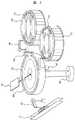
図2は、本発明の一実施形態による分析システムに用いる免疫分析モジュールの構成を示す平面図である。
【0018】
複数の試薬容器20は、試薬ディスク21上に円状に配列される。試薬ディスク21は、モータにより回転される。複数個の反応容器22は、恒温槽23上に円状に配置される。恒温槽23は、モータにより回転される。恒温槽23の回転動作によって、反応容器22は、反応容器設置位置24から試料分注位置25,試薬分注位置26及び反応液吸引位置27へと移動される。
【0019】
試料分注ピペッタ28は、試料吸引位置29から試料分注位置25に、モータにより移動可能である。検体ラック30が引込線51に引き込まれ、その検体ラックによって保持されて、試料吸引位置29に位置付けられた検体(試料)を試料分注位置25にある反応容器22に分注するときは、試料分注ピペッタ28のノズルの先端に使い捨てチップ31が装着される。
【0020】
試薬分注ピペッタ32は、試薬吸引位置33から試薬分注位置26に移動可能である。シッパ34は、反応液吸引位置27,緩衝液吸引位置35およびフローセル内部用洗浄位置36間で移動可能である。又、シッパ34は、チューブを介して、検出ユニット37内のフローセルまで反応液を送る機能を持っている。
【0021】
チップおよび反応容器移送機構38は、使い捨てチップ31を、チップ保管位置39からチップ装着位置55へ、また、反応容器33を、反応容器保管位置40から反応容器設置位置24へと移送する。試薬分注ピペッタ32およびシッパ34は、それぞれの洗浄位置で自身のノズルを洗浄する。
【0022】
次に、免疫分析モジュール5の動作を説明する。
【0023】
最初に、チップおよび反応容器移送機構38は、使い捨てチップ31をチップ装着位置55へ、また、反応容器22を反応容器設置位置24へ移送する。検体が試料吸引位置29に位置付けられると、試薬ディスク21は、その検体の分析に用いる試薬の入った試薬容器20を試薬吸引位置33に位置付けるように回転すると共に、試料分注ピペッタ28は、ノズルに使い捨てチップ31を装着した後、試料吸引位置29に移動し、試料(検体)を吸引する。試料吸引後、試料分注ピペッタ28は試料分注位置25に移動され、吸引した試料を反応容器22に放出する。その放出後、試料分注ピペッタ28は、チップ廃棄位置41に移動されて、先端のチップは廃棄される。
【0024】
試料が放出された反応容器22は、反応ディスク23の回転により、試薬分注位置26に移動される。試薬分注ピペッタ32は、試薬吸引位置33にある試薬を吸引し、これを試薬分注位置26に移動された反応容器22に放出される。試薬と試料との免疫反応液の入った反応容器22は、一定時間経過後、反応ディスク23の回転により、反応液吸引位置27に移動される。シッパ34は、その反応液を吸引し、さらに、緩衝液吸引位置35に移動して緩衝液を吸引し、チューブを介して検出ユニット37内のフローセルに移す。これによって光学的測定が行われ、免疫分析項目の分析結果が得られる。その後、シッパ34は、フローセル内部用洗浄位置36に移動され、フローセル内部用洗浄液を吸引して、チューブを介してフローセルに流し、フローセルを洗浄する。
【0025】
次に、図3を用いて、本実施形態による分析システムに用いる生化学モジュールの構成について説明する。なお、図3においては、図1に示した生化学分析モジュール7を例にして説明するが、生化学分析モジュール8も、同様の構成である。
【0026】
また、図1と同一符号は、同一部分を示している。
【0027】
図3は、本発明の一実施形態による分析システムに用いる生化学分析モジュールの構成を示す平面図である。
【0028】
生化学モジュール7は、複数の第1の試薬41が、それぞれ円状に配列された第1の試薬ディスク43と、複数の第2の試薬42が、それぞれ円状に配列された第2の試薬ディスク44と、第1および第2の試薬分注ピペッタ45,46とを含む試薬系と、試料分注ピペッタ47を含むサンプル系と、恒温槽48からの恒温槽が循環する反応ディスク49上に複数個の反応容器50が配列されている反応系と、多波長光度計52を含む測定系(分析系)とを備えている。
【0029】
検体ラック30が引込線71に引き込まれ、その検体ラックに保持されて、試料吸引位置に位置付けられた検体(試料)は、試料分注ピペッタ47により吸引され、反応ディスク49の反応容器50に試料分注位置において放出される。試料が放出された反応容器50は、反応ディスク49の回転により、第1の試薬分注位置に移動され、そこで、その反応容器50には第1の試薬ディスク43に保持されている第1の試薬41が、第1の試薬ピペッタ45により分注される。第1の試薬が分注された反応容器50は、攪拌位置に移動され、そこで攪拌位置53により試料と第1の試薬との攪拌が行われる。
【0030】
更に、第2の試薬の添加が必要な場合は、攪拌処理済みの反応容器50は、第2の試薬分注位置に移動され、そこで、反応容器50には、第2の試薬ディスク44に保持されている第2の試薬42が第2の試薬ピペッタ46によって分注される。分注済みの反応容器50は、攪拌位置に移動され、そこで、攪拌装置53により反応容器50内の試料,第1の試薬及び第2の試薬の攪拌が行われ、その反応液が生成される。
【0031】
反応液が入った反応容器50は、測定位置に移動され、そこで、多波長光度計52により、反応液の多波長吸光度測定が行われ、生化学分析項目の分析結果が得られる。
【0032】
次に、図4を用いて、本実施形態による自動分析システムにおける試薬が不足した際の試薬を交換可能とする処理動作について説明する。なお、以下の説明では、本実施形態による自動分析システムにおいて自動分析処理の実行中に、分析モジュール5の特定の試薬の残量が不足し、当該試薬の測定を継続不可能になった場合の試薬交換を例にして説明する。他の分析モジュール6,7,8において試薬の残量が不足し、当該試薬の測定を継続不可能になった場合の試薬交換も同様である。
【0033】
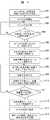
図4は、本発明の一実施形態による自動分析システムにおける特定の試薬の残量が不足し、当該試薬の測定を継続不可能になった場合の処理動作を示すフローチャートである。
【0034】
図5は、本発明の一実施形態による分析モジュールの操作部18での試薬交換項目の設定例を示す説明図である。
【0035】
ステップ401において、分析モジュールに対して、試薬の交換を促す測定の項目名を指定し、登録ボタン500を押すことにより項目名Aの試薬を指定有502にて設定する。
【0036】
ステップ402において、分析スタートボタン501を選択することにより、自動分析システムの全体管理用コンピュータ11は、通常のルーチン分析を実行する。
【0037】
そして、ステップ403において、各モジュール用コンピュータ12〜15は、分析を実行する。
【0038】
そして、ステップ404において、モジュール用コンピュータ12は、分析の途中で項目名Aの試薬の残量が不足するか否かを判断する。試薬が不足しない場合には、ステップ403に戻り、モジュールでの分析を続行し、試薬が不足すると、ステップ405に進む。なお、以下の説明では、項目名Aの試薬が不足したものとする。他の試薬交換を指定有とした項目名504の試薬が不足した場合でも同様である。また、試薬交換を指定無とした項目名505の試薬が不足した場合は、ステップ403のモジュールでの分析を継続し、項目名505を除く、他の項目名の分析を行う。
【0039】
ステップ405において、モジュール用コンピュータ12は、モジュールでの新たな検体(試料)に対する分析を一時停止し、既に検体(試料)を吸引している項目を継続して測定する。そして、ステップ406において、分析を一時停止したことで未測定となった検体を検体ラック待機部9へ搬送する。
【0040】
ステップ407において、自動分析システムの全体管理用コンピュータ11は、分析モジュール5を試薬の交換が必要な分析モジュールとして登録する。そして、ステップ408において、表示部19に試薬Aの交換が必要であることを表示する。なお、以下の説明では、分析モジュール5にて試薬が不足したものとする。試薬交換が必要な状態の表示は、例えば、全体管理用コンピュータ11に接続された表示部19に表示される。表示部19には、分析モジュール5,…,8等が模式的に表示されており、例えば、分析モジュール5にて試薬の交換が必要な場合には、分析モジュール5の表示503を、「緑色」の常時点灯状態から、「桃色」で点滅状態に変えることにより、表示する。
【0041】
ステップ409において、分析モジュール5での試薬の交換を可能とする。ステップ409の操作を実施している間、自動分析システムの全体管理用コンピュータ11は、分析モジュール6,…,8にルーチンの分析を依頼し、分析を継続する。
【0042】
そして、ステップ410において、モジュール用コンピュータ12は、試薬の交換を終了したことを、分析モジュール5に取付けられた検出器80の信号によって検出し、交換された試薬の残量を試薬分注ピペッタ32に取付けられた液面検知センサの信号により確認する。
【0043】
ステップ411において、全体管理用コンピュータ11は、項目名Aの試薬の残量が有りになっているか否かを判断する。試薬が不足したままである場合には、ステップ408に戻り、表示部19に試薬交換が必要であることを表示し、再度、試薬Aの交換を促す。試薬が補充されて、残量が有る場合には、ステップ412に進む。
【0044】
ステップ412において、全体管理用コンピュータ11は、分析モジュール5を試薬の交換を終了した分析モジュールとして再登録する。
【0045】
そして、ステップ413において、全体管理用コンピュータ11は、分析モジュール5をルーチンの分析モジュールとして自動分析システムに復帰させる。
【0046】
さらに、ステップ414において、検体ラック待機部に搬送されていた検体を分析モジュール5に移動し、測定を停止していた検体の分析を再開する。
【0047】
なお、以上の説明は、項目名Aの一つの試薬が不足したものとして説明したが、項目名Aの分析を行うために必要とする試薬は一つである必要は無い。項目名Aの分析で使用する洗浄液,希釈液及び前処理液が不足した場合についても同様に適用できるものである。即ち、項目名Aの一つの試薬の残量が有りの場合でも、洗浄液または希釈液及び前処理液の一つでも残量が不足していた場合に、モジュール用コンピュータ12は、ステップ404にて項目名Aの洗浄液不足または希釈液不足及び前処理液不足として判断し、ステップ405に進むこともある。
【0048】
以上説明したように、本実施形態によれば、複数の分析モジュールの内の1モジュールにて分析可能な試薬が無くなった場合でも、システム全体を止めることなく、試薬の交換を可能とし、分析を続行できるものとなる。
【発明の効果】
分析モジュールに試薬不足が発生してもシステム全体の分析効率を低下させずに分析を続行することができる分析システムを提供することができる。
【図面の簡単な説明】
【図1】本発明の一実施形態による自動分析システムの全体構成を示すシステムブロック図である。
【図2】本発明の一実施形態による分析システムに用いる免疫分析モジュールの構成を示す平面図である。
【図3】本発明の一実施形態による分析システムに用いる生化学分析モジュールの構成を示す平面図である。
【図4】本発明の一実施形態による自動分析システムのシステム操作の手順を示すフローチャートである。
【図5】本発明の一実施形態による分析モジュールの試薬交換項目の設定例を示す説明図である。
【符号の説明】
1…検体ラック投入部、2…ID読取部、3…搬送ライン、4…再検査用搬送ライン、5,6,7,8…分析モジュール、9…検体ラック待機部、10…検体ラック回収部、11…全体管理用コンピュータ、12,13,14,15,16,17…各分析モジュール用コンピュータ、18…操作部、19…表示部、51,61,71,81…引込線。[0001]
BACKGROUND OF THE INVENTION
The present invention relates to an automatic analysis system including an automatic analyzer that automatically analyzes biological samples such as blood and urine, and more particularly, to automatically connect a plurality of automatic analyzers and mount a reagent in each analyzer. It relates to an analysis system.
[0002]
[Prior art]
Conventionally, in an automatic analyzer that analyzes a sample (specimen) derived from a living body such as blood and urine, analysis has been performed using a so-called stand-alone apparatus that performs analysis independently by each apparatus. However, recently, in order to improve the work efficiency in the laboratory, it is possible to measure multiple items with high throughput with a configuration in which multiple automatic analyzers (hereinafter referred to as analysis modules) are connected via a transport line. An analysis system has been proposed. In Japanese Patent Laid-Open No. 9-243646, the same type of reagent is mounted on one of a plurality of analysis modules connected to the transport line, and when the reagent of one analysis module runs short, the other mounted with the same type of reagent. An automatic analysis system is disclosed in which analysis can be continued without stopping the entire analysis system for reagent replacement by transporting a sample to be analyzed to this analysis module.
[0003]
[Problems to be solved by the invention]
As a countermeasure when a reagent shortage occurs in a certain analysis module, the analysis item in which the subsequent reagent shortage has occurred in that analysis module cannot be analyzed. Analyzed items that are deficient are masked from the beginning as if the analyzed items could not be analyzed.) When the analysis is continued, the analysis of the relevant analysis module is suspended and the reagent is replaced by the operator. There are two ways to continue. Depending on the type of reagent, it is better to replace the reagent each time it is used frequently and there is a reagent shortage. Some of the analysis modules in which a shortage of reagents is generated by performing an analysis in the module are preferably continued with masking the lacking reagents (in order not to lower the analysis efficiency). Japanese Patent Laid-Open No. 9-243646 does not describe how to use them properly. That is, the timing of when the operator replaces the reagent is not considered for the analysis module in which the reagent shortage occurs.
[0004]
An object of the present invention is to provide an analysis system capable of continuing an analysis without reducing the analysis efficiency of the entire system even when a reagent shortage occurs in the analysis module.
[0005]
[Means for Solving the Problems]
The configuration of the present invention for achieving the object of the present invention is as follows.
[0006]
A transport line that transports the sample rack from the rack delivery section to the rack collection section, and supports the reaction section, the sample dispensing section that dispenses the sample on the sample rack to the reaction section, and the analysis items to the reaction section In an analysis system in which a plurality of analyzers each having a reagent supply unit that supplies a reagent to be disposed are arranged along the transport line, and a plurality of samples are analyzed by the plurality of analyzers, the reagents in the reagent supply unit of the analyzer A reagent shortage detection unit for detecting that any of the plurality of analyzers is in shortage, and a reagent shortage occurrence display means for notifying that a reagent shortage has occurred when the reagent shortage detection unit has detected a reagent shortage of any of the plurality of analyzers And an analysis system comprising: a control disconnecting unit that disconnects the analyzer in which the reagent shortage has occurred from the control of the analysis system based on the reagent shortage detection information from the reagent shortage detection unit. Temu.
[0007]
DETAILED DESCRIPTION OF THE INVENTION
Hereinafter, the configuration and operation of an automatic analysis system according to an embodiment of the present invention will be described with reference to FIGS.
[0008]
Initially, the whole structure of the automatic analysis system by this embodiment is demonstrated using FIG.
[0009]
FIG. 1 is a system block diagram showing the overall configuration of an automatic analysis system according to an embodiment of the present invention.
[0010]
The automatic analysis system according to this embodiment includes a sample rack input unit 1, an ID reading unit 2, a
[0011]
The sample rack loading unit 1 is a portion for loading a plurality of sample racks each holding a plurality of samples (samples). The
[0012]
In the present embodiment, a combination of a biochemical analysis module and an immune analysis module is shown, but it may be configured by a combination with other analysis modules, for example, a gene analysis module.
[0013]
The
[0014]
The
[0015]
The sample held by the sample rack has a sample ID indicating information on the sample (reception number, patient name, requested analysis item, etc.), and the sample rack has a rack ID indicating rack identification information such as a rack number. Have. The sample rack placed in the sample rack input unit 1 is transported by the
[0016]
Next, the configuration of the immune analysis module used in the analysis system according to the present embodiment will be described with reference to FIG. In FIG. 2, the
[0017]
FIG. 2 is a plan view showing the configuration of the immune analysis module used in the analysis system according to the embodiment of the present invention.
[0018]
The plurality of
[0019]
The
[0020]
The
[0021]
The chip and reaction
[0022]
Next, the operation of the
[0023]
First, the chip and reaction
[0024]
The
[0025]
Next, the configuration of the biochemical module used in the analysis system according to the present embodiment will be described with reference to FIG. In FIG. 3, the biochemical analysis module 7 shown in FIG. 1 is described as an example, but the biochemical analysis module 8 has the same configuration.
[0026]
The same reference numerals as those in FIG. 1 denote the same parts.
[0027]
FIG. 3 is a plan view showing the configuration of the biochemical analysis module used in the analysis system according to the embodiment of the present invention.
[0028]
The biochemical module 7 includes a
[0029]
The
[0030]
Further, when it is necessary to add the second reagent, the stirred
[0031]
The
[0032]
Next, with reference to FIG. 4, a processing operation that allows the reagent to be replaced when the reagent is insufficient in the automatic analysis system according to the present embodiment will be described. In the following description, when the automatic analysis process according to the present embodiment is performed, the remaining amount of a specific reagent in the
[0033]
FIG. 4 is a flowchart showing a processing operation when the remaining amount of a specific reagent is insufficient in the automatic analysis system according to the embodiment of the present invention, and measurement of the reagent cannot be continued.
[0034]
FIG. 5 is an explanatory diagram showing a setting example of reagent replacement items on the
[0035]
In
[0036]
In
[0037]
In
[0038]
In
[0039]
In
[0040]
In
[0041]
In
[0042]
In
[0043]
In
[0044]
In
[0045]
In
[0046]
In
[0047]
Although the above description has been made assuming that one reagent of item name A is insufficient, it is not necessary that one reagent is required to perform analysis of item name A. The same applies to the case where the cleaning liquid, dilution liquid and pretreatment liquid used in the analysis of item name A are insufficient. That is, even when there is a remaining amount of one reagent of item name A, when the remaining amount of one of the cleaning liquid, the dilution liquid, and the pretreatment liquid is insufficient, the
[0048]
As described above, according to the present embodiment, even when there is no reagent that can be analyzed in one of a plurality of analysis modules, the reagent can be replaced without stopping the entire system, and analysis can be performed. You will be able to continue.
【The invention's effect】
It is possible to provide an analysis system capable of continuing an analysis without reducing the analysis efficiency of the entire system even if a reagent shortage occurs in the analysis module.
[Brief description of the drawings]
FIG. 1 is a system block diagram showing the overall configuration of an automatic analysis system according to an embodiment of the present invention.
FIG. 2 is a plan view showing a configuration of an immune analysis module used in an analysis system according to an embodiment of the present invention.
FIG. 3 is a plan view showing a configuration of a biochemical analysis module used in the analysis system according to the embodiment of the present invention.
FIG. 4 is a flowchart showing a system operation procedure of the automatic analysis system according to the embodiment of the present invention.
FIG. 5 is an explanatory diagram showing a setting example of reagent replacement items of the analysis module according to the embodiment of the present invention.
[Explanation of symbols]
DESCRIPTION OF SYMBOLS 1 ... Sample rack input part, 2 ... ID reading part, 3 ... Conveyance line, 4 ... Reexamination conveyance line, 5, 6, 7, 8 ... Analysis module, 9 ... Sample rack standby part, 10 ... Sample rack collection part 11 ... Computer for overall management, 12, 13, 14, 15, 16, 17 ... Computer for each analysis module, 18 ... Operation unit, 19 ... Display unit, 51, 61, 71, 81 ... Lead-in line.
Claims (9)
Translated fromJapanese前記分析装置に設置した試薬の残量不足を検出する試薬不足検出部と、
試薬が不足した場合は、当該試薬の交換を促す測定の項目名を登録する登録手段と、
該登録手段に登録してある特定の試薬について前記試薬不足検出部が残量不足を検出したとき、試薬不足が発生した分析装置を分析システムの制御から切り離すよう制御する制御切り離し手段と、
を備えたことを特徴とする分析システム。In an analysis system in which a plurality of analyzers are arranged along a transport line and a sample is analyzed by the plurality of analyzers,
A reagent shortage detection unit for detecting a shortage of the remaining amount of the reagent installed in the analyzer;
When the reagent is insufficient, a registration means for registering the item name of the measurement for prompting replacement of the reagent,
Control disconnecting means for controlling the analyzer in which the reagent shortage has occurred to be disconnected from the control of the analysis system when the reagent shortage detecting unit detects a shortage of the remaining amount for the specific reagent registered in theregistering means ;
An analysis system characterized by comprising:
前記登録手段に登録した以外の試薬が不足した場合は、試薬不足が発生した分析装置を分析システムの制御から切り離すことなく分析を継続するように制御する制御手段と、
を備えたことを特徴とする分析システム。The analysis system according to claim 1,
Control means for controlling to continue the analysis without disconnecting the analyzer in which the reagent shortage has occurred from the control of the analysis system when there is a shortage of reagents other than those registered in the registration means;
An analysis system characterized by comprising:
前記分析装置に、新たに試薬を設置したことを検出する新規試薬検出部を備え、
前記試薬不足が発生した分析装置に、不足した試薬を設置したことを前記新規試薬検出部が検出したことに応じて、前記制御切り離し手段に対し制御の切り離しを停止し、分析システムの制御に復帰するよう指示する機構を備えたことを特徴とする分析システム。The analysis system according to claim 1,
The analyzer includes a new reagent detection unit that detects that a new reagent has been installed,
In response to the new reagent detection unit detecting that the missing reagent has been installed in the analyzer in which the reagent shortage has occurred, the control detachment means is stopped, and control is returned to the analysis system. An analysis system comprising a mechanism for instructing to do so.
前記制御切り離し手段が試薬不足が発生した分析装置を分析システムの制御から切り離す前に、該分析装置上にある未分析の検体ラックを前記搬送ラインに戻す機構を備えたことを特徴とする分析システム。The analysis system according to claim 1,
An analysis system comprising: a mechanism for returning an unanalyzed sample rack on the analyzer to the transport line before the control separation unit disconnects the analyzer in which the reagent shortage has occurred from the control of the analysis system. .
システムから切り離された分析装置に交換する試薬を設置している時間の間、
システム全体の分析を停止することなく、システムから切り離された前記分析装置にて分析する予定の検体を待機させておくことが可能なバッファを備えたことを特徴とする分析システム。The analysis system according to claim 1,
During the time that the reagent to be replaced is installed in the analyzer disconnected from the system
An analysis system comprising: a buffer capable of waiting for a sample to be analyzed by the analyzer separated from the system without stopping the analysis of the entire system.
システムから切り離された分析装置で交換した試薬の残量を、システム全体に復帰する前に自動で測定する機構を備えたことを特徴とする分析システム。The analysis system according to claim3 .
Analysis systemthat is characterized in that a mechanism for automatically measured before the remaining amount of the reagent has been replaced in the analysis device is disconnected from the system, to return the entire system.
システムから切り離された分析装置で交換した試薬が、試薬が不足していた測定の項目と一致することをシステム全体に復帰する前に自動で確認し、一致しない場合にはシステムに復帰しない機構を備えたことを特徴とする分析システム。The analysis system according to claim3 .
Before returning to the entire system, the reagent replaced by the analyzer disconnected from the system automatically matches the measurement item that lacked the reagent.analysis systemthat is characterized by comprising.
前記システム全体の制御から自動的に切り離したことを、前記不足した試薬を知らせることで、交換すべき試薬を特定可能とする手段を有することを特徴とする分析システム。The analysis system according to claim 1,
Analysis systemthat further comprising a means for that automatically disconnected from the control of the entire system, by notifying the reagent the insufficient possible to specify the reagent to be replaced.
システム全体に復帰する前に自動で確認し、不足していた試薬を知らせることで、交換すべき試薬を識別可能とする手段を有することを特徴とする分析システム。The analysis system according to claim 8, wherein
Check automatically before returning to the overall system, by notifying the reagent missing,analyze systemthat is characterized in that it comprises means for enabling identification of the reagent to be replaced.
Priority Applications (3)
| Application Number | Priority Date | Filing Date | Title |
|---|---|---|---|
| JP2002189014AJP3990943B2 (en) | 2002-06-28 | 2002-06-28 | Automatic analysis system |
| EP03014652.6AEP1376139B1 (en) | 2002-06-28 | 2003-06-26 | Automatic analyzing system |
| US10/606,835US7556771B2 (en) | 2002-06-28 | 2003-06-27 | Automatic analyzing system |
Applications Claiming Priority (1)
| Application Number | Priority Date | Filing Date | Title |
|---|---|---|---|
| JP2002189014AJP3990943B2 (en) | 2002-06-28 | 2002-06-28 | Automatic analysis system |
Publications (2)
| Publication Number | Publication Date |
|---|---|
| JP2004028931A JP2004028931A (en) | 2004-01-29 |
| JP3990943B2true JP3990943B2 (en) | 2007-10-17 |
Family
ID=29717663
Family Applications (1)
| Application Number | Title | Priority Date | Filing Date |
|---|---|---|---|
| JP2002189014AExpired - LifetimeJP3990943B2 (en) | 2002-06-28 | 2002-06-28 | Automatic analysis system |
Country Status (3)
| Country | Link |
|---|---|
| US (1) | US7556771B2 (en) |
| EP (1) | EP1376139B1 (en) |
| JP (1) | JP3990943B2 (en) |
Families Citing this family (16)
| Publication number | Priority date | Publication date | Assignee | Title |
|---|---|---|---|---|
| US7628954B2 (en)* | 2005-05-04 | 2009-12-08 | Abbott Laboratories, Inc. | Reagent and sample handling device for automatic testing system |
| JP4832121B2 (en)* | 2006-03-10 | 2011-12-07 | シスメックス株式会社 | Analysis system |
| JP4906431B2 (en)* | 2006-08-04 | 2012-03-28 | 株式会社日立ハイテクノロジーズ | Automatic analyzer |
| US20090181359A1 (en)* | 2007-10-25 | 2009-07-16 | Lou Sheng C | Method of performing ultra-sensitive immunoassays |
| US8222048B2 (en) | 2007-11-05 | 2012-07-17 | Abbott Laboratories | Automated analyzer for clinical laboratory |
| JP4672034B2 (en)* | 2008-02-12 | 2011-04-20 | 株式会社日立ハイテクノロジーズ | Automatic analyzer |
| CN104237542B (en)* | 2008-09-03 | 2016-11-02 | 株式会社日立高新技术 | Automatic analysis device |
| JP5280797B2 (en)* | 2008-10-27 | 2013-09-04 | シスメックス株式会社 | Sample analyzer |
| CN101900720B (en)* | 2009-05-29 | 2014-09-10 | 希森美康株式会社 | Specimen processing device and specimen processing method |
| JP5358336B2 (en)* | 2009-07-31 | 2013-12-04 | 株式会社日立ハイテクノロジーズ | Automatic analyzer |
| CN103460053B (en)* | 2011-04-15 | 2016-01-27 | 深圳迈瑞生物医疗电子股份有限公司 | Body fluid workstation and its online reagent loading method and system |
| JP6072450B2 (en)* | 2012-07-12 | 2017-02-01 | 株式会社日立ハイテクノロジーズ | Automatic analyzer |
| JP5963601B2 (en)* | 2012-08-01 | 2016-08-03 | オリンパス株式会社 | Imaging apparatus, imaging method, and program |
| JP6411125B2 (en) | 2014-08-07 | 2018-10-24 | Dmg森精機株式会社 | Tool changer |
| WO2021042340A1 (en)* | 2019-09-05 | 2021-03-11 | 深圳迈瑞生物医疗电子股份有限公司 | Reagent replacement method and sample analyzer |
| JP7008744B2 (en) | 2020-04-14 | 2022-01-25 | 日本電子株式会社 | Automatic analyzer and control method of automated analyzer |
Family Cites Families (21)
| Publication number | Priority date | Publication date | Assignee | Title |
|---|---|---|---|---|
| JPS5782769A (en)* | 1980-11-10 | 1982-05-24 | Hitachi Ltd | Automatic analyzing device |
| DE3680317D1 (en)* | 1986-01-31 | 1991-08-22 | Nittec Koganei Kk | AUTOMATIC ANALYZER. |
| JPH0666813A (en)* | 1992-08-17 | 1994-03-11 | Toshiba Corp | Automatic analyzer |
| JP2996860B2 (en)* | 1994-03-18 | 2000-01-11 | 株式会社日立製作所 | Automatic analyzer |
| US5679309A (en)* | 1995-12-14 | 1997-10-21 | Beckman Instruments, Inc. | Automated random access analyzer |
| JP2988362B2 (en)* | 1996-03-11 | 1999-12-13 | 株式会社日立製作所 | Multi-sample analysis system |
| US6733728B1 (en)* | 1996-03-11 | 2004-05-11 | Hitachi, Ltd. | Analyzer system having sample rack transfer line |
| JP3493910B2 (en)* | 1996-08-23 | 2004-02-03 | 株式会社日立製作所 | Automated processing system |
| JP3597958B2 (en)* | 1996-11-15 | 2004-12-08 | 株式会社日立製作所 | Automatic analyzer |
| JP3428426B2 (en)* | 1997-03-26 | 2003-07-22 | 株式会社日立製作所 | Sample analysis system |
| DE69835181T2 (en)* | 1997-04-09 | 2006-11-23 | Hitachi, Ltd. | Automatic sample analysis system and method of operation |
| DE69837230T2 (en)* | 1997-04-10 | 2007-12-20 | Hitachi, Ltd. | Automatic analyzer |
| DE69942220D1 (en)* | 1998-07-27 | 2010-05-20 | Hitachi Ltd | Method for handling body fluid samples and analyzer. which uses these |
| JP3866446B2 (en)* | 1999-05-07 | 2007-01-10 | 株式会社東芝 | Automatic analyzer |
| JP2000321283A (en)* | 1999-05-13 | 2000-11-24 | Toshiba Corp | Automatic analyzer |
| JP2002048802A (en)* | 2000-08-07 | 2002-02-15 | Hitachi Ltd | Automatic analysis system |
| US6723288B2 (en)* | 2002-04-29 | 2004-04-20 | Dade Behring Inc. | Method of providing assay processing in a multi-analyzer system |
| US7850912B2 (en)* | 2003-05-14 | 2010-12-14 | Dako Denmark A/S | Method and apparatus for automated pre-treatment and processing of biological samples |
| US7185288B2 (en)* | 2003-07-18 | 2007-02-27 | Dade Behring Inc. | Operator interface module segmented by function in an automatic clinical analyzer |
| US7381370B2 (en)* | 2003-07-18 | 2008-06-03 | Dade Behring Inc. | Automated multi-detector analyzer |
| US7029922B2 (en)* | 2003-07-18 | 2006-04-18 | Dade Behring Inc. | Method for resupplying reagents in an automatic clinical analyzer |
- 2002
- 2002-06-28JPJP2002189014Apatent/JP3990943B2/ennot_activeExpired - Lifetime
- 2003
- 2003-06-26EPEP03014652.6Apatent/EP1376139B1/ennot_activeExpired - Lifetime
- 2003-06-27USUS10/606,835patent/US7556771B2/ennot_activeExpired - Lifetime
Also Published As
| Publication number | Publication date |
|---|---|
| JP2004028931A (en) | 2004-01-29 |
| US7556771B2 (en) | 2009-07-07 |
| US20040091396A1 (en) | 2004-05-13 |
| EP1376139A2 (en) | 2004-01-02 |
| EP1376139A3 (en) | 2010-08-04 |
| EP1376139B1 (en) | 2017-06-14 |
Similar Documents
| Publication | Publication Date | Title |
|---|---|---|
| US6579717B1 (en) | Specific solution handling method for calibration and quality control by automatic analytical apparatus | |
| US7341691B2 (en) | Automatic analyzing apparatus | |
| JP3990943B2 (en) | Automatic analysis system | |
| JP5178830B2 (en) | Automatic analyzer | |
| JP3558898B2 (en) | Automatic analyzer and automatic analysis method | |
| US8343772B2 (en) | Specimen processing device, specimen conveyance device, and specimen conveyance method | |
| JP6320535B2 (en) | Automatic analyzer | |
| JP2002048802A (en) | Automatic analysis system | |
| EP1293781A2 (en) | Transfer unit and automatic analyzing apparatus having such transfer unit | |
| JP5815917B2 (en) | Rack transport device | |
| JP3609945B2 (en) | Automatic analysis method and apparatus | |
| JP2008209338A (en) | Automatic analyzer | |
| JP2001091523A (en) | Automatic analyzer | |
| JP2004271265A (en) | Automatic analyzer | |
| JP2020073883A (en) | Analysis method of automatic analyzer | |
| JP2008122421A (en) | Automatic analyzer and rack transport method | |
| JP3391734B2 (en) | Biological sample handling method and analyzer | |
| JP3990945B2 (en) | Automatic analyzer | |
| JP3626032B2 (en) | Automatic analysis method and automatic analyzer | |
| JP4153171B2 (en) | Analysis method of biological sample | |
| JP4101466B2 (en) | Biological sample analyzer | |
| JP3380542B2 (en) | Biological sample analysis method | |
| JP3632537B2 (en) | Automatic analyzer and analysis method using the same | |
| JP3109443U (en) | Automatic analyzer | |
| JP4537472B2 (en) | Analysis equipment |
Legal Events
| Date | Code | Title | Description |
|---|---|---|---|
| A621 | Written request for application examination | Free format text:JAPANESE INTERMEDIATE CODE: A621 Effective date:20050511 | |
| A521 | Request for written amendment filed | Free format text:JAPANESE INTERMEDIATE CODE: A523 Effective date:20050511 | |
| A977 | Report on retrieval | Free format text:JAPANESE INTERMEDIATE CODE: A971007 Effective date:20060302 | |
| A131 | Notification of reasons for refusal | Free format text:JAPANESE INTERMEDIATE CODE: A131 Effective date:20060328 | |
| RD02 | Notification of acceptance of power of attorney | Free format text:JAPANESE INTERMEDIATE CODE: A7422 Effective date:20060510 | |
| RD04 | Notification of resignation of power of attorney | Free format text:JAPANESE INTERMEDIATE CODE: A7424 Effective date:20060510 | |
| A521 | Request for written amendment filed | Free format text:JAPANESE INTERMEDIATE CODE: A523 Effective date:20060515 | |
| A131 | Notification of reasons for refusal | Free format text:JAPANESE INTERMEDIATE CODE: A131 Effective date:20061024 | |
| A521 | Request for written amendment filed | Free format text:JAPANESE INTERMEDIATE CODE: A523 Effective date:20061211 | |
| A02 | Decision of refusal | Free format text:JAPANESE INTERMEDIATE CODE: A02 Effective date:20070327 | |
| A521 | Request for written amendment filed | Free format text:JAPANESE INTERMEDIATE CODE: A523 Effective date:20070427 Free format text:JAPANESE INTERMEDIATE CODE: A523 Effective date:20070528 | |
| A911 | Transfer to examiner for re-examination before appeal (zenchi) | Free format text:JAPANESE INTERMEDIATE CODE: A911 Effective date:20070605 | |
| TRDD | Decision of grant or rejection written | ||
| A01 | Written decision to grant a patent or to grant a registration (utility model) | Free format text:JAPANESE INTERMEDIATE CODE: A01 Effective date:20070717 | |
| A61 | First payment of annual fees (during grant procedure) | Free format text:JAPANESE INTERMEDIATE CODE: A61 Effective date:20070723 | |
| FPAY | Renewal fee payment (event date is renewal date of database) | Free format text:PAYMENT UNTIL: 20100727 Year of fee payment:3 | |
| R150 | Certificate of patent or registration of utility model | Ref document number:3990943 Country of ref document:JP Free format text:JAPANESE INTERMEDIATE CODE: R150 Free format text:JAPANESE INTERMEDIATE CODE: R150 | |
| FPAY | Renewal fee payment (event date is renewal date of database) | Free format text:PAYMENT UNTIL: 20110727 Year of fee payment:4 | |
| FPAY | Renewal fee payment (event date is renewal date of database) | Free format text:PAYMENT UNTIL: 20110727 Year of fee payment:4 | |
| FPAY | Renewal fee payment (event date is renewal date of database) | Free format text:PAYMENT UNTIL: 20120727 Year of fee payment:5 | |
| FPAY | Renewal fee payment (event date is renewal date of database) | Free format text:PAYMENT UNTIL: 20130727 Year of fee payment:6 | |
| S531 | Written request for registration of change of domicile | Free format text:JAPANESE INTERMEDIATE CODE: R313531 | |
| S533 | Written request for registration of change of name | Free format text:JAPANESE INTERMEDIATE CODE: R313533 | |
| R350 | Written notification of registration of transfer | Free format text:JAPANESE INTERMEDIATE CODE: R350 | |
| EXPY | Cancellation because of completion of term |