JP3990803B2 - Film sticking method - Google Patents
Film sticking methodDownload PDFInfo
- Publication number
- JP3990803B2 JP3990803B2JP06860498AJP6860498AJP3990803B2JP 3990803 B2JP3990803 B2JP 3990803B2JP 06860498 AJP06860498 AJP 06860498AJP 6860498 AJP6860498 AJP 6860498AJP 3990803 B2JP3990803 B2JP 3990803B2
- Authority
- JP
- Japan
- Prior art keywords
- film
- roll
- substrate
- adhesive tape
- cover film
- Prior art date
- Legal status (The legal status is an assumption and is not a legal conclusion. Google has not performed a legal analysis and makes no representation as to the accuracy of the status listed.)
- Expired - Fee Related
Links
Images


Landscapes
- Laminated Bodies (AREA)
- Lining Or Joining Of Plastics Or The Like (AREA)
Description
Translated fromJapanese【0001】
【発明の属する技術分野】
この発明は、フィルム張付方法、特に、プリント配線盤用基板や液晶パネル用ガラス基板、プラズマディスプレイ用の基板に例示される基板の表面にフィルムを張り付けるためのフィルム張付方法に関する。
【0002】
【従来の技術】
上記のようなフィルム張付方法は、例えば図5(A)に示されるように、透光性支持フィルム12A上に感光性樹脂層12B及びカバーフィルム12Cを積層して形成された積層体フィルム12から、前記カバーフィルム12Cを剥離させた後に、前記感光性樹脂層12B側が基板に密着するようにして、一対のラミネーティングロール間に送り込み熱圧着するものである。
【0003】
圧着の方式として、積層体フィルム12を予め基板長さに応じて切断してから熱圧着するもの、及び、基板を一定間隔をもって順次搬送しつつ、これに沿ってフィルムを切断することなく連続的に重ね合わせて供給し、両者を回転する一対のラミネーティングロール間に送り込み、熱圧着する連続張りタイプのものがある。
【0004】
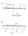
連続張りタイプのフィルム張付方法においては、フィルム供給ロールから積層体フィルムを巻き出し、図5(A)に示されるように、図5(B)の基板16、16間の間隔よりも少し幅広に間隔をもって、ディスクカッター44A、44Bによりカバーフィルム12Cを切断し、切断後に、前記基板16、16間に相当する部分のカバーフィルム12Cを残し、他の部分のカバーフィルム12Cを剥離してから、ラミネーティングロール間に基板と共に送り込み、図5(B)に示される状態に張り付けるようにしたものがある。
【0005】
ここで、上記のように、カバーフィルム12Cを間欠的に剥離させる場合、粘着テープの粘着面を外側にして巻き掛けたタッチロールを前記カバーフィルム12Cに離接させて、所定部分だけ剥離するものがある。
【0006】
最近、液晶ディスプレイやプラズマディスプレイ用の基板は、非常に大型化し、積層体フィルムの幅が70cm以上となることが多い。
【0007】
【発明が解決しようとする課題】
このように、積層体フィルムが広幅になると、粘着テープによるカバーフィルムの剥離ミスが生じ易く、又基板への張付前の状態で、積層体フィルムの張力が幅方向に不均一であったり、長手方向に変動したりすると、基板への張付状態で皺が発生することが多い。
【0008】
特に、粘着テープは、積層体フィルムの全幅にわたってカバーフィルムに粘着するものではなく、カバーフィルムの幅方向複数箇所で、カバーフィルムと比較して細幅(一般には幅が20mm程度)の粘着テープを押し付けて、カバーフィルムを剥離するようにしているので、カバーフィルムの剥離ミスが生じ易く、又粘着テープの、カバーフィルムへの押し付けタイミングや離間タイミング、あるいは押し付け及び離間時に積層体フィルムを厚さ方向に引張ることによって、積層体フィルムの張力に変動を与え易いという問題点がある。
【0009】
この発明は、上記従来の問題点に鑑みてなされたものであって、積層体フィルムに張力変動を与えることなく円滑に且つ確実に、カバーフィルムを間欠的に剥離して、積層体フィルムに皺が発生しないように基板に張り付けるようにしたフィルム張付方法を提供することを目的とする。
【0010】
【課題を解決するための手段】
この発明は、基板搬送面に沿って、複数の基板を間隔をもって順次搬送する工程と、透光性支持フィルムに少なくとも感光性樹脂層及びこの外側を被うカバーフィルムを積層してなる積層体フィルムをフィルムロールから巻き出し、ハーフカッターにより、前記カバーフィルムを、長手方向の適宜間隔で、厚さ方向には少なくとも透光性支持フィルムを残して幅方向に切断してハーフカット線を形成するハーフカット工程と、ハーフカット工程を経たカバーフィルムの長手方向少なくとも一部をハーフカット線から剥離させる剥離工程と、この剥離工程によりカバーフィルムが剥がされ、感光性樹脂層の長手方向少なくとも一部が露出された積層体フィルムを、前記露出された感光性樹脂層の側を、前記搬送されてくる基板の一方の面に向けて、これと重なるように、且つ、基板搬送方向と同方向に搬送する送り工程と、前記搬送されてくる基板及び積層体フィルムを、回転する一対のラミネーティングロール間に通して圧着する圧着工程と、を含んでなるフィルム張付方法において、
前記カバーフィルムの剥離工程は、前記剥離を開始する、ハーフカット線から次のハーフカット線までは剥離、該剥離終端のハーフカット線から次のハーフカット線までは非剥離とし、粘着層を前記カバーフィルム側に向けた状態の粘着テープを巻き掛けたタッチロールと、前記タッチロールの中心軸線よりも前記積層体フィルムの送り方向後側に中心軸線がずれて設定され、前記タッチロールと共に前記積層体フィルムを挟持可能な受けロールとを配置し、カバーフィルムの剥離開始時に、前記粘着テープを、前記積層体フィルムと同方向に等速で移動させつつ、前記剥離を開始するハーフカット線よりもその進行方向前方の非剥離部分における進行方向後半部分から、前記タッチロールにより前記粘着テープを受けロール方向に押して粘着テープをカバーフィルムに圧着させ、剥離終端の前記ハーフカット線よりもその進行方向前方位置で前記タッチロール及び粘着テープを前記積層体フィルムから離間させることにより、上記目的を達成するものである。
【0011】
又、前記粘着テープ押し付けのとき、前記タッチロールを積層体フィルムの進行方向前方から前記受けロールに向けて駆動すると共に、この受けロール外周に対して外接面となる前記積層体フィルムの通過面と受けロールとの接点の、積層体フィルムの進行方向前方位置で、積層体フィルムに粘着テープを介して押圧させるようにしてもよい。
【0012】
更に、前記タッチロールによりカバーフィルムに粘着され、これを積層体フィルムから剥ぎ取った粘着テープを、ニップロールにより、その厚さ方向に挟持して前記積層体フィルムと等速で引張るようにしてもよい。
【0013】
又、前記タッチロールの、積層体フィルム進行方向後側に隣接する位置で、タッチロールが受けロールから離間するとき、積層体フィルムのカバーフィルム側の面を押え部材により、積層体フィルムがその通過面にあるように押えるようにしてもよい。
【0014】
更に又、前記ハーフカッターの上流位置で、積層体フィルムの巻き出し量を検出し、この検出値に基づき、前記ハーフカット工程におけるカバーフィルムのハーフカット線が前記タッチロールの手前近傍に到達するタイミングを予測し、この予測されたタイミングに合致するように、前記タッチロールにより前記粘着テープをカバーフィルムに押圧させるようにしてもよい。
【0015】
この発明においては、カバーフィルムの剥離を開始させるハーフカット線よりも、その進行方向前方位置で、タッチロールにより粘着テープを押し付けて、且つ粘着テープを積層体フィルムと略同方向且つ等速で移動させつつ巻き取るので、積層体フィルムに与える張力変動を極めて小さくして、カバーフィルムを円滑に剥離させることができる。従って、フィルムを基板に張り付ける際に、張力変動による皺の発生を抑制することができる。
【0016】
【発明の実施の形態】
以下本発明の実施の形態の例について図面を参照して詳細に説明する。
【0017】
図1は、本発明に係るフィルム張付方法を実施するためのフィルム張付装置10を示す。
【0018】
このフィルム張付装置10は、基板搬送面14Aに沿って複数の基板16を一定間隔で順次搬送する基板搬送装置14と、前述のような積層体フィルム12をロールにしてなるフィルムロール18と、このフィルムロール18と一対のラミネーティングロール20A、20Bとの間にフィルムロール18側から、ハーフカッター22、カバーフィルム剥離装置24、サクションロール26、フリー回転のガイドロール28A、フィルムガイドロール52をこの順で配置し、フィルムロール18から巻き出した積層体フィルム12の、カバーフィルム12Cを所定位置で、前記ハーフカッター22によって切断してハーフカット線を形成し、次に、カバーフィルム剥離装置24によって、カバーフィルム12Cの、各ハーフカット線間部分のうち基板16に張付けるべき部分のみを間欠的に剥離し、感光性樹脂層12Bを露出させた状態で、前記一対のラミネーティングロール20A、20B間に送り込み、ここで、基板搬送装置14によって搬送されてくる基板16の対応箇所に露出された感光性樹脂層12Bが重なるようにして、前記一対のラミネーティングロール20A、20Bにより熱圧着するものである。
【0019】
この一対のラミネーティングロール20A、20Bは、金属製ロールの外周に、シリコーンゴム、あるいは表面がフッ素樹脂等の非粘着性被膜で被覆されたシリコーンゴム等の弾性材料を設けて構成され、又、ヒーター(図示省略)を内蔵し、装置の運転開始に先立って、表面が100°〜150℃にまで加熱され、運転中は常時回転されている。
【0020】
前記ラミネーティングロール20A、20Bの出側には、第1ニップロール30、フルカッター32、及び、第2ニップロール34が、ラミネーティングロール20A、20B側からこの順で基板搬送方向に配置されている。
【0021】
前記フィルムロール18の出側近傍には上下一対のフリーロール36A、36Bが配置され、上側のフリーロール36Aの上端と、前記サクションロール26の上端とがほぼ同一水平面上に位置するようにされている。
【0022】
又、前記サクションロール26は、その表面に多数の吸引孔(図示省略)が形成され、ここに印加される負圧によって、巻き掛けられている積層体フィルム12を吸着し、前記フリーロール36A、36Bとの間及びラミネーティングロール20A、20Bとの間で積層体フィルム12に所定の張力を付与できるようにされている。
【0023】
なお、前記フィルムロール18に、トルクモータ18Aによりフィルム巻取り方向のトルクがかけられた状態で積層体フィルム12が巻き出されることにより、積層体フィルム12に引張力(後述のサクションロール26との間での張力は、積層体フィルム12の幅が1000mmのとき、2〜10Kg好ましくは5Kg前後がよい)が発生するようにされている。
【0024】
又、前記フリーロール36Aには、ロータリエンコーダ38が接続され、積層体フィルム12がサクションロール26方向に送られるときのフリーロール36Aの回転数に応じたパルスを制御装置40(図2参照)に出力するようにされている。
【0025】
前記ハーフカッター22は、図3及び図4に示されるように、前記サクションロール26とフリーロール36Aとの間で水平に送られる積層体フィルム12の送り面とほぼ一致する吸着面42Aを備えたカッター台42と、このカッター台42の上面に沿ってフィルム幅方向に往復動自在の一対のディスクカッター44A、44Bとを有して構成され、これらカッター台42及びディスクカッター44A、44Bを、積層体フィルム12と等速でその送り方向に移動させつつ、該ディスクカッター44A、44Bをフィルム幅方向に移動して、積層体フィルム12の図において上面側のカバーフィルム12Cを、透光性支持フィルム12Aを残して切断するようにされている。
【0026】
前記一対のディスクカッター44A、44Bは、積層体フィルム12の送り方向に離間して設けられ、且つその距離は、図5に示されるように、前記基板搬送面14Aを搬送される先行基板16の後端と後行基板16の先端間の距離よりもわずかに大きくなるようにされている。
【0027】
前記カッター台42及びディスクカッター44A、44Bの、積層体フィルム送り方向の往復動はラックアンドピニオン機構46により、又、ディスクカッター44A、44Bのフィルム幅方向の往復動は、一軸ロボット48によってそれぞれなされ、これらラックアンドピニオン機構46及び一軸ロボット48は、前記制御装置40によって制御される。
【0028】
前記ラックアンドピニオン機構46は、カッター台42と一体のラック46Aと、このラック46Aをフィルム送り方向、且つ、水平に往復動自在に支持するレール46Bと、前記ラック46Aと噛み合って、これをレール46Bに沿って駆動するピニオン46Cと、を含んで構成されている。
【0029】
前記カッター台42はフィルム幅方向に長く配置され、その上面に、前記ディスクカッター44A、44Bの刃先を受ける、例えば合成樹脂からなる棒状のカッター受け45A、45Bがフィルム幅方向に埋込み配置されている。
【0030】
前記ラック46A上には前記一軸ロボット48が配置され、この一軸ロボット48はボールねじ機構(図示省略)を有し、前記ディスクカッター44A、44Bを支持する支持台45をフィルム幅方向に駆動するようにされている。
【0031】
前記カバーフィルム剥離装置24は、図1、図6に示されるように、前記ハーフカッター22とサクションロール26の間の位置で、フィルム通過面13における積層体フィルム12の下側に接触する受けロール24A、24Bと、サクションロール26に近い側の前記受けロール24Bに上方から離接自在のタッチロール24Cと、片面に粘着層が形成され、その粘着層を図1、図6において下側にして、前記タッチロール24Cに巻き掛けられた粘着テープ24Dと、この粘着テープ24Dの先端を巻き取る巻取り装置24Eと、を備えている。
【0032】
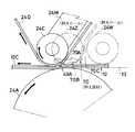
図1の符号24Fは、前記受けロール24Aの上側位置で、受けロール24Aと共に自重により、積層体フィルム12を挟み込み、カバーフィルム12Cが上向きに引張られるときに積層体フィルム12が浮き上がることを防止するためのニップロール、24Gは、粘着テープ24Dの供給源であるテープロール24Hに巻取り方向のトルクを付与することによって、粘着テープ24Dに張力を与えるためのテープブレーキ、24I、24Jは、タッチロール24Cと巻取り装置24Eとの間で粘着テープ24Dを挟み込むニップロール、24Kは、ニップロール24Jを前記積層体フィルム12の送り速度と等速で、粘着テープ24Dを巻取る方向に駆動させるモータ、24Lは、巻取り装置24Eにおける巻取りロールを駆動するためのモータ、図6の符号24Mは、前記タッチロール24Cを受けロール24Bに離接自在に支持する揺動レバー、24Nは揺動レバー24Mを駆動するためのタッチシリンダをそれぞれ示す。
【0033】
前記ニップロール24Iは、その表面が粗面化された(通常、表面粗さRaが10μm程度)ロールであり、詳細には、外周が金属であり、且つ、この金属表面がブラスト処理されると共にフッ素樹脂、シリコーン樹脂等の離型性コーティングがなされていて、粘着テープ24の粘着層、カバーフィルム12Cに付着している感光性樹脂が粘着しないようにされている。
【0034】
前記タッチシリンダ24Nは、前記制御装置40によって制御され、前記ハーフカッター22によって切断されたカバーフィルム12Cの、ディスクカッター44A、44B間部分の、フィルム送り方向(図6の矢印方向)の略前半部には粘着テープ24が接触しないようにし、且つ、フィルム送り方向の略後半部から、後側のディスクカッター44Aのハーフカット線49A(図6において右側)を含む部分に接触して、該ハーフカット線49Aからカバーフィルム12Cの剥離を開始し、次のディスクカッター44Bのハーフカット線49Bの手前までの間、カバーフィルム12Cに粘着テープ24Dを粘着させるように揺動レバー24Mを介してタッチロール24Cを駆動するようにされている。
【0035】
粘着テープ24Dは、これに粘着されたカバーフィルム12Cと共にニップロール24I、24Jを経て巻取り装置24Eにより巻き取られることにより、カバーフィルム12Cを感光性樹脂層12Bから剥離するようにされている。
【0036】
従って、透光性支持フィルム12A上には、図5、図6に示されるように、基板16の搬送ピッチと等しいピッチで、ディスクカッター44A、44B間に等しい長さのカバーフィルム12Cが残されることになる。
【0037】
なお、図7に示されるように、タッチロール24Cは受けロール24Bの頂点よりも図においてわずかに左側にずれた位置で、積層体フィルム12の進行方向前方からカバーフィルム12Cを押圧するようにされている。
【0038】
図6の符号24Pはニップロール24Iを揺動自在に支持するレバー、24Qは、レバー24Pを、ニップロール24Iがニップロール24Jに圧接する方向に付勢するためのばね、24Rはガイドロール、24Sは、粘着テープ24Dに剥離されたカバーフィルム12Cが付着しているか否かを確認するための剥離確認センサ、24Tは前記揺動レバー24を揺動自在に支持する支持軸、24Uは支持軸24Tに回転自在に支持され、テープロール24Hから巻き出された粘着テープ24Dの非粘着面側が巻き掛けられるガイドロールをそれぞれ示す。
【0039】
又、符号24Xは両端が装置フレーム(図示省略)に取付けられ、前記受けロール24A、24B等と平行に配置された支持バーを示す。この支持バー24Xは、前記タッチシリンダ24Nを支持すると共に、略U字形状の板ばね24Yを介して前記ガイドロール24Rを回転自在に支持している。
【0040】
ガイドロール24Rは、板ばね24Yが弾力的に変形することにより、粘着テープ24Dにたるみが生じないようにしている。
【0041】
前記一対のラミネーティングロール20A、20Bのうち、上側のラミネーティングロール20Aは、ロールクランプシリンダ50によって、下側のラミネーティングロール20Bに押圧される「閉」位置、及び、両者間を通る基板16及び積層体フィルム12に非接触となり得るように上方に離間した「開」位置との間で駆動されるようになっている。
【0042】
前記第1及び第2ニップロール30、34は、それぞれ第1クランプシリンダ30A、第2クランプシリンダ34Aによって下側の搬送ロール15Aに対して上方から離接自在とされ、搬送ロール15Aとの間に積層体フィルム12又は積層体フィルム12と基板16を挟み込んだとき、搬送ロール15Aの回転によってこれらを図1において右方向に搬送できるようにされている。
【0043】
図1、図8の符号15Bは、ラミネーティングロール20A、20Bの前後に配置され、前記搬送ロール15Aと同期して等速で回転される搬送ロールを示す。
【0044】
前記フルカッター32は、前記第1及び第2ニップロール30、34との間の位置で、基板搬送装置14によって搬送される基板と同期して移動しつつ、各基板間の位置で積層体フィルム12をその幅方向に切断するものである。
【0045】
フルカッター32は、基板搬送面14Aの下側に沿って基板搬送方向に同期して移動すると共に、反対方向に戻るように往復動されるカッター台32Aと、このカッター台32Aと共に基板搬送方向に往復動し、且つ、基板搬送面14Aに沿って搬送される基板16に対してカッター台32Aが同期して走行する間に、フィルム幅方向に走行して、カッター台32Aとの間で積層体フィルム12を切断するカッター刃32Bと、このカッター刃32Bを基板幅方向に走行させるための走行駆動装置32Cと、前記カッター台32A、カッター刃32B、走行駆動装置32Cを、基板搬送方向に同期して走行(往動)させるラックアンドピニオン機構(図示省略)、及び、急速に復動させる走行シリンダ32Dと、を備えて構成されている。
【0046】
なお、復動時には、上記ピニオンと駆動モータとの間のクラッチ(ともに図示省略)が切られるようになっている。
【0047】
又、図1の符号54は、ラミネーティングロール20A、20Bの入側に配置され、積層体フィルム12を加熱するためのフィルムヒータを示す。前記フィルムガイドロール52は、前記フィルムヒータ54の上流側に配置され、積層体フィルム12のフィルムパスを、前記一対のラミネーティングロール20A、20Bの両方に非接触となる中立位置に変更すると共に、ラミネーティングロール20A、20Bによりフィルム張付動作中は積層体フィルム12と非接触となるように、揺動自在に配置されている。
【0048】
前記基板搬送面14Aの下側には、前記ラミネーティングロール20A、20Bの入側近傍位置に基板後端センサを兼ねる後続基板スタートセンサ56及びこれより上流側に離間した位置に基板先端センサを兼ねる基板待機センサ58が、更に、後続基板スタートセンサ56の上流側に基板搬送面14Aの一部を構成するフリーロール59が配置されている。
【0049】
図1の符号60は、基板搬送装置14におけるコンベアロール14C及びその上流の搬送ロール列14Bを駆動するためのコンベアロール駆動用のサーボモータ、62は、コンベアロール14Cとの間に基板16を挟み込んで基板の搬送を安定させるためのニップロール、62Aは、ニップロール62を開閉させるためのシリンダ、64は、基板搬送面14A上を搬送中の基板16が過剰に温度低下しないように加熱するための保温ヒータをそれぞれ示す。
【0050】
前記基板搬送面14Aに沿って、前記保温ヒータ64の上流側には、図9に示されるように、基板幅寄せ装置68が配置され、更に上流側には基板ヒータ(図示省略)が配置されている。
【0051】
前記基板幅寄せ装置68は、搬送ロール列68A、この搬送ロール列68A上に搬送されてきた基板16を持ち上げてから前記保温ヒータ64の下方に水平に送り込み、下降して搬送ロール列14B上に基板16を移載し、搬送ローラ列68Aの下側位置に戻るロボット68Bと、前記ロボット68Bにより搬送ロール列68Aの上方に持ち上げられている基板16を、左右から押すことにより幅方向のセンタリングをする幅寄せロール列68Cと、を有して構成されている。
【0052】
図9の符号68Dは搬送ロール列68Aの入側に配置された基板位置検出センサ、68Eは出側に配置された基板位置検出センサをそれぞれ示す。
【0053】
前記ロボット68Bは、基板16を載置するための、基板搬送方向に長い水平の基板載置面を備え、この基板載置面には、負圧が印加され、基板16を吸着して水平に保持する複数の吸着孔(図示省略)が設けられると共に、基板16の部分的冷却を抑制するためにヒーター(図示省略)が設けられている。
【0054】
ここで、前記第1、第2ニップロール30、34及び、ニップロール62は金属性ロールの外周に、シリコーンゴム、あるいは表面がフッ素樹脂等の非粘着性被膜で被覆されたシリコーンゴム等の弾性材料を設けて構成されている。
【0055】
前記ニップロール62は、前記基板待機センサ58が基板の先端を検出したときの出力信号に基づいて、前記制御装置40を介して、シリンダ62Aによって下降され、コンベアロール14Cとの間で基板16を挟持できるようにされている。
【0056】
前記サーボモータ60は後続基板スタートセンサ56が、基板搬送面14A上に送り込まれた基板の先端を検出したとき、制御装置40により速度「零」とされ、一時基板を停止させ、次に、基板16が積層体フィルム12と同期するようなタイミング及び速度で回転されるようになっている。
【0057】
なお、前記ラミネーティングロール20A、20Bよりも下流側の搬送ロール15Aと、上流側のコンベアロール14C及び搬送ロール列14Bと、搬送ロール列68Aとは相互に別個独立して、その回転、停止を制御装置40により制御されるようになっている。
【0058】
又、前記サクションロール26の負圧は、ガイドロール28Aに加わる力をロードセル27により検出して、この検出値、即ち積層体フィルム12にかかる張力が一定になるように制御装置40により調整される。
【0059】
図1の符号18Bは、フィルムロール18のフィルム残量センサ、24Vは巻き取り装置24Eにおけるフィルム巻き取り量センサを示す。これらのセンサ18B、24Vはともに、ロールの半径方向に複数の光センサを配置してなるラインセンサであり、フィルム残量、フィルム巻き取り量に対応して信号を出力するようにされている。
【0060】
次に、上記フィルム張付装置10において、積層体フィルム12の先端をフィルムロール18から巻き出してラミネーティングロール20A、20B間に通してセットする過程について説明する。
【0061】
積層体フィルム12の巻き出しに先立ち、前記カバーフィルム剥離装置24のタッチロール24Cは、カバーフィルム12Cに接触しない位置としておき、又、前記フィルムガイドロール52は、積層体フィルム12がラミネーティングロール20A、20Bに非接触となる位置に揺動しておく。又、トルクモータ18AをONとし、積層体フィルム12の巻き出し時に引張力が生じるようにしておく。
【0062】
更に、フィルムヒータ54、前記保温ヒータ64を所定温度に昇温させ、又、その上流側の基板ヒータにより基板16を所定温度(100〜150℃)に加熱しておき、ラミネーティングロールロール20A、20Bも同程度に昇温させると共に常時回転状態としておく。
【0063】
フィルムロール18から巻き出した積層体フィルム12の先端は、図8に示されるように、予め開かれているラミネーティングロール20A、20B間を通って第1及び第2ニップロール30、34の位置まで引張り、この状態で第1及び第2クランプシリンダ30A、34Aにより、第1、第2ニップロール30、34を下降させて、搬送ロール15Aとの間に挟み込む。
【0064】
フィルム張付作業の開始に際しては、ラミネーティングロール20A、20Bの下流側の搬送ローラ15A、サクションロール26を駆動させ、積層体フィルム12をフィルムロール18から巻き出して送りをかける。
【0065】
同時に、ハーフカッター22を積層体フィルム12と同期して走行させつつ、ディスクカッター44A、44Bをフィルム幅方向に駆動し、カバーフィルム12Cを切断する。
【0066】
なお、このとき、ディスクカッター44A、44Bによるカバーフィルム12Cの切断を完全にするためには、ディスクカッター44A、44Bを感光性樹脂層12Bも切断し、更に透光性支持フィルム12Aにもわずかに食い込むようにするとよい。
【0067】
前記ハーフカッター22によるカバーフィルム12Cのハーフカット線の位置は、ロータリエンコーダ38から出力されるパルス信号の数によって分かり、又、このパルス信号によって図1において右側のディスクカッター44Aによるハーフカット線49Aが、前記カバーフィルム剥離装置24におけるタッチロール24Cの位置に到達するタイミングが分かる。
【0068】
従って、このタイミングで制御装置40により、タッチシリンダ24Nを介してタッチロール24Cを下降させ、該タッチロール24Cに巻き掛けられている粘着テープ24Dの粘着面のカバーフィルム12Cへの押付けを、カバーフィルム12Cにおける剥離部のフィルム送り方向中央位置から前記ディスクカッター44Aによるハーフカット線49Aの直前位置までの間で開始する。
【0069】
前記受けロール24Bの回転中心軸は、この受けロール24Bの外周に積層体フィルム12及び粘着テープ24Dを介して接触する状態の前記タッチロール24Cの中心軸線よりも、積層体フィルム送り方向後側にわずかにずれているので、受けロール24Bに接触する積層体フィルム12は、カバーフィルム12C側が凸の湾曲面となり、ハーフカット線49A部分が開かれるようになる。
【0070】
従って、このハーフカット線49Aの前方側から粘着テープ24Dの粘着面が接触してくると、カバーフィルム12Cは、前記ディスクカッター44Aによるハーフカット線49Aの位置から容易に剥離が開始され、粘着テープ24Dと共に巻取り装置24Eに巻き取られる。
【0071】
ここで、前記粘着テープ24Dは、モータ24Kによって駆動されるニップロール24Jにより、積層体フィルム12Cと等速で且つ、タッチロール24Cの位置では同方向に引張られているので、粘着テープ24Dがカバーフィルム12Cに離接することにより積層体フィルム12に与えられる張力変動を極めて小さくすることができる。
【0072】
なお、粘着テープ24Dの粘着面のカバーフィルム12Cへの押付け開始タイミングが、上記より早すぎると非剥離部のカバーフィルム12Cが剥がされてしまい、又、遅すぎると剥離不能となる。
【0073】
次に、前記粘着テープ24Dと共に剥離されたカバーフィルム12Cが前記ニップロール24I、24Jに挟み込まれるタイミングから、ハーフカッター22による次の切断によって生じた、ディスクカッター44Bによるハーフカット線49Bがタッチロール24Cの位置に到達する直前までの間に、制御装置40によってタッチロール24Cは積層体フィルム12から離間する方向に駆動され、粘着テープ24Dに粘着したカバーフィルム12Cは、ディスクカッター44Bによるハーフカット線位置で積層体フィルム12から離れる。
【0074】
これにより、ディスクカッター44A、44Bによるハーフカット線49A、49B間部分のカバーフィルム12Cは、剥離されることなく透光性支持フィルム12A及び感光性樹脂層12B上に残され、サクションロール26を経てラミネーティングロール20A、20B方向に送られる。
【0075】
なお、タッチロール24Cを積層体フィルム12から離間させるタイミングが前記よりも早すぎると、粘着テープ24Dに粘着していたカバーフィルム12Cが積層体フィルム12に引張られて、粘着テープ24Dから剥離してしまうことがある。又、遅すぎると、粘着テープ24Dが次の非剥離部のカバーフィルム12Cに粘着して、これを剥がしてしまうことがある。
【0076】
前記最初の切断によるカバーフィルム12C上のディスクカッター44Aによるハーフカット線49Aが、ラミネーティングロール20A、20Bに接近する前に基板幅寄せ装置68を経て保温ヒータ64下方の搬送ローラ列14B上に先頭の基板16を搬送しておく。基板16の先端が基板待機センサ58により検出されると、基板16の先端に合致するタイミングでニップロール62が制御装置40により下降されて基板16をコンベアロール14Cとの間に挟持する。
【0077】
搬送ロール列14B及びコンベアロール14Cはサーボモータ60により、搬送速度「零」とされた後、前記カバーフィルム12C上のハーフカット線49Aが先頭基板16の送り方向先端からわずかに後ろ寄りの位置に一致するタイミング及び速度で積層体フィルム12に同期して基板16が基板搬送装置14によりラミネーティングロール20A、20B間に送り込まれる。
【0078】
この先頭の基板16の先端部分が、ラミネーティングロール20A、20Bに到達するタイミングは、前記基板待機センサ58の位置とラミネーティングロール20A、20B間の距離、及び、サーボモータ60による搬送速度との関係から割り出される。
【0079】
又、このようにして割り出された基板16の先端が、ラミネーティングロール20A、20Bに到達するタイミングで、ロールクランプシリンダ50によって上側のラミネーティングロール20Aが下降され、下降したラミネーティングロール20Aと下側のラミネーティングロール20B間に先頭の基板16の先端が積層体フィルム12と共に挟み込まれ、且つラミネーティングロール20A、20Bの回転によって、熱圧着されつつ、図1において右方向に送られる。
【0080】
上記上側のラミネーティングロール20Aを下降するタイミングで、前記フィルムガイドロール52は図1において積層体フィルム12から離間する方向に駆動される。これによって、積層体フィルム12はラミネーティングロール20A、20Bによって挟持されるようになる。
【0081】
なお、基板16に張り付けられた部分よりも送り方向先端側の積層体フィルム12は、カバーフィルム12Cが張り付けられたまま第2ニップロール34の位置から基板搬送面14Aよりも下側に送られ、先頭基板16の先端よりもやや前方位置で、積層体フィルム12が前記フルカッター32によって切断されるとき、第2ニップロール34から下方に廃棄される。
【0082】
以上のように、このフィルム張付装置10によるフィルム張付方法においては、フィルムロール18から巻き出した積層体フィルム12の、ハーフカット線間部分を残して、基板16に張り付けられる部分のカバーフィルム12Cを粘着テープ24Dによって確実に剥離させると共に、積層体フィルム12に与える引張力の変動が少なく、従って、積層体フィルム12を基板16に張り付けた際における皺の発生を抑制することができる。
【0083】
又、このフィルム張付装置10においては、フィルムロール18から巻き出した積層体フィルム12の巻き出し先端から、これを第2ニップロール34を通った位置にセットしたときのハーフカッター22によるカット位置までの間の部分を、カバーフィルム12Cが張り付けられたままとしているので、感光性樹脂層12Bが露出することがなく、露出した感光性樹脂層12Bがニップロール等に付着して、運転開始後にこれに巻き付いたりすることがない。
【0084】
従来は、フィルムロール18から巻き出した積層体フィルム12の巻き出し先端からカバーフィルム12Cを剥離し、感光性樹脂層12Bを露出した状態でセットしていたが、感光性樹脂層12Bは、カバーフィルム12Cを剥離した後、30秒程度経過すると空気中の酸素によって変質してしまうので、この範囲では、基板16に張り付けたりすることなく廃棄していた。
【0085】
なお、上記フィルム張付装置10において、粘着テープ24Dをカバーフィルム12Cに押し付けて剥離を開始させた後、剥離を終了させる際にタッチロール24Cが受けロール24Bから離間することによって、積層体フィルム12全体が、受けロール24Aとニップロール24Jとによって挟み込まれる位置を中心として、図6において上方に揺動されるように引張られる。
【0086】
従って、フィルム12に張力変動を与えるが、この張力変動が過大の場合は、基板16に張り付けられた積層体フィルム12に皺を発生させる。
【0087】
この場合、図7において二点鎖線で示されるように、前記タッチロール24Cよりもフィルム送り方向後側に隣接した位置で、積層体フィルムを図において水平状のフィルム通過面13に維持するような押えロール24Wを設けるとよい。
【0088】
このようにすると、タッチロール24Cが受けロール24Bから離間する方向に移動したとき、積層体フィルム12がタッチロール24Cと共に上方に移動することを、押えロール24Wにより押えて、防止できる。従って、積層体フィルム12に与える張力変動をわずかにすることができる。
【0089】
更に、前記押さえロール24Wは、タッチロール24C、粘着テープ24Dと干渉しなければ、図7において2点鎖線24Zで示されるように、前記受けロール24Aの直上位置までの範囲なら前進させて設けてもよい。この場合、フィルム幅方向に間欠的に配置されたタッチロール24C、粘着テープ24Dのフィルム幅方向の隙間であって、これらに隣接する位置に押さえロールを配置するとよい。
【0090】
又、積層体フィルム12を、その水平なフィルム通過面13に維持するものはロールに限定されず、図7において符号70で示されるような押え部材としてもよい。
【0091】
この押え部材70は、前記フィルム通過面13と平行なステンレスチール板70Aの下側に、下向きに凸の樹脂70Bを接着してなり、前記支持バー24Xから板ばね70Cを介して弾力的に支持され、フィルム通過面13からわずかに上方に離れた状態とされている。
【0092】
又、上記フィルム張付装置10の場合、フィルムロール18から巻き出した積層体フィルム12の巻き出し先端部分をニップロールにより挟持してセットしているが、これは上側のラミネーティングロール20Aを下降して、ラミネーティングロール20Bとの間に積層体フィルム12を挟持させてもよい。
【0093】
又、フィルムガイドロール52はラミネーティングロール20Aの直前上流側に設けてもよい。更に、カバーフィルム12Cの剥離手段は粘着テープに限定されるものでなく、粘着性ロールあるいは負圧による吸引装置、例えば負圧が印加される多数の吸引孔が形成された吸引ロールを用いたものであってもよい。
【0094】
【発明の効果】
本発明は上記のように構成したので、フィルムロールから巻き出した積層体フィルムのカバーフィルムを、粘着テープによって、ハーフカット線間位置で間欠的に剥離させるとき、粘着テープの離接により、積層体フィルムに与える張力変動を最小限に抑制して、基板へのフィルム張付時における皺の発生を防止することができるという優れた効果を有する。
【図面の簡単な説明】
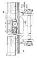
【図1】本発明に係るフィルム張付方法を実施するためのフィルム張付装置を示す一部ブロック図を含む略示側面図
【図2】同フィルム張付装置における制御系を示すブロック図
【図3】同フィルム張付装置におけるハーフカッターを拡大して示す平面図
【図4】図3のIV−IV線視図
【図5】同ハーフカッターによる切断位置と基板と位置関係を拡大して示す略示側面図
【図6】同フィルム張付装置におけるカバーフィルム剥離装置の作用を拡大して示す略示側面図
【図7】同カバーフィルム剥離装置におけるタッチロールと積層体フィルムとの関係を拡大して示す側面図
【図8】同フィルム張付装置における積層体フィルムの巻き出し先端部のセット状態を示す略示側面図
【図9】同フィルム剥離装置における基板幅寄せ装置及び保温ヒータを示す略示側面図
【符号の説明】
10…フィルム張付装置
12…積層体フィルム
12A…透光性支持フィルム
12B…感光性樹脂層
12C…カバーフィルム
13…フィルム通過面
14…フィルム剥離装置
14A…基板搬送面
16…基板
18…フィルムロール
20A、20B…ラミネーティングロール
22…ハーフカッター
24…カバーフィルム剥離装置
24A…受けロール
24C…タッチロール
24D…粘着テープ
24E…巻取り装置
24J…ニップロール
24K…モータ
24W、24Z…押えロール
30…第1ニップロール
34…第2ニップロール
38…ロータリエンコーダ
40…制御装置
44A、44B…ディスクカッター
49A、49B…ハーフカット線
70…押え部材[0001]
BACKGROUND OF THE INVENTION
The present invention relates to a film sticking method, and more particularly to a film sticking method for sticking a film to the surface of a substrate exemplified by a printed wiring board substrate, a liquid crystal panel glass substrate, and a plasma display substrate.
[0002]
[Prior art]
For example, as shown in FIG. 5A, the film sticking method as described above is a
[0003]
As the method of pressure bonding, the laminated
[0004]
In the continuous tension type film sticking method, the laminate film is unwound from the film supply roll, and as shown in FIG. 5 (A), it is slightly wider than the distance between the
[0005]
Here, as described above, when the
[0006]
Recently, substrates for liquid crystal displays and plasma displays have become very large, and the width of the laminate film is often 70 cm or more.
[0007]
[Problems to be solved by the invention]
Thus, when the laminate film becomes wide, mistakes in peeling of the cover film due to the adhesive tape are likely to occur, and the tension of the laminate film is uneven in the width direction before being attached to the substrate. In many cases, wrinkles are generated in the state of being attached to the substrate.
[0008]
In particular, the pressure-sensitive adhesive tape does not adhere to the cover film over the entire width of the laminate film, but is a narrow width (generally about 20 mm in width) of the pressure-sensitive adhesive tape at multiple locations in the width direction of the cover film. Since the cover film is peeled off by pressing, it is easy for mistakes in the peeling of the cover film, and the laminated film is in the thickness direction when the adhesive tape is pressed against or separated from the cover film, or when pressed and separated. There is a problem in that the tension of the laminate film is easily changed by pulling on the film.
[0009]
The present invention has been made in view of the above-described conventional problems. The cover film is intermittently and smoothly peeled off without giving a fluctuation in tension to the laminate film, and the laminate film is peeled off. An object of the present invention is to provide a film sticking method in which the film is attached to a substrate so as not to occur.
[0010]
[Means for Solving the Problems]
The present invention relates to a laminate film formed by laminating a plurality of substrates sequentially at intervals along a substrate carrying surface, and laminating a translucent support film with at least a photosensitive resin layer and a cover film covering the outside. A half-cut line is formed by unwinding the cover film from a film roll, and cutting the cover film in the longitudinal direction at an appropriate interval in the longitudinal direction by cutting in the width direction, leaving at least a translucent support film in the thickness direction. A cutting step, a peeling step for peeling at least a part of the longitudinal direction of the cover film that has undergone the half-cutting step from the half-cut line, and the peeling step removes the cover film, thereby exposing at least a part of the longitudinal direction of the photosensitive resin layer. The laminated film is directed so that the exposed photosensitive resin layer side faces one side of the transported substrate. A feeding process for transporting in the same direction as the substrate transport direction, and a crimping process for crimping the transported substrate and laminated film between a pair of rotating laminating rolls so as to overlap with the substrate transport direction. In a film sticking method comprising:
The peeling process of the cover film starts the peeling, peeling from a half-cut line to the next half-cut line, non-peeling from the half-cut line at the peeling end to the next half-cut line, A touch roll wrapped with an adhesive tape in a state facing the cover film side,and a center axis is set to be shifted to the rear side in the feeding direction of the laminate film with respect to the center axis of the touch roll , and the laminate together with thetouch roll Than a half-cut line that starts the peeling while moving the adhesive tape at a constant speed in the same direction as the laminated film at the start of peeling of the cover film. thetraveling direction latter half of the non-peeled portion of the forward traveling direction, viscosity push the roll direction receives the adhesive tape by the touch roll To crimp the tape cover film, by separating the touch roll and the adhesive tape from the laminate film in the traveling direction of forward position than the half-cut line of the release end, it is to achieve the above object.
[0011]
Further, when pressing the adhesive tape, the touch roll is driven from the front in the traveling direction of the laminated film toward the receiving roll, and the passing surface of the laminated film which is a circumscribed surface with respect to the outer circumference of the receiving roll; The laminated film may be pressed via an adhesive tape at a position in front of the laminated film in the advancing direction of the contact point with the receiving roll.
[0012]
Further, the adhesive tape that is adhered to the cover film by the touch roll and peeled off from the laminate film may be sandwiched in the thickness direction by the nip roll and pulled at the same speed as the laminate film. .
[0013]
Further, when the touch roll is separated from the receiving roll at a position adjacent to the rear side in the traveling direction of the laminate film in the touch roll, the laminate film passes through the cover film side surface of the laminate film by the pressing member. You may make it press so that it may exist in a surface.
[0014]
Furthermore, the amount of unwinding of the laminate film is detected at the upstream position of the half cutter, and the timing at which the half cut line of the cover film in the half cut process reaches near the front of the touch roll based on the detected value. And the adhesive tape may be pressed against the cover film by the touch roll so as to coincide with the predicted timing.
[0015]
In this invention, the adhesive tape is pressed by the touch roll at a position ahead of the half cut line that starts the peeling of the cover film, and the adhesive tape is moved in the same direction and at the same speed as the laminated film. Since it winds up, it can make the tension | tensile_strength fluctuation | variation given to a laminated body film very small, and can peel a cover film smoothly. Therefore, when the film is attached to the substrate, generation of wrinkles due to fluctuations in tension can be suppressed.
[0016]
DETAILED DESCRIPTION OF THE INVENTION
Hereinafter, an example of an embodiment of the present invention will be described in detail with reference to the drawings.
[0017]
FIG. 1 shows a film sticking apparatus 10 for carrying out the film sticking method according to the present invention.
[0018]
The film sticking device 10 includes a substrate transport device 14 that sequentially transports a plurality of
[0019]
The pair of laminating rolls 20A and 20B is configured by providing an elastic material such as silicone rubber or silicone rubber whose surface is coated with a non-adhesive film such as a fluororesin on the outer periphery of a metal roll, A heater (not shown) is incorporated, and the surface is heated to 100 ° C. to 150 ° C. prior to the start of operation of the apparatus, and is always rotated during operation.
[0020]
On the exit side of the laminating rolls 20A and 20B, a
[0021]
A pair of upper and lower
[0022]
Further, the
[0023]
In addition, when the
[0024]
A
[0025]
As shown in FIGS. 3 and 4, the
[0026]
The pair of
[0027]
The reciprocating motion of the cutter table 42 and the
[0028]
The rack and
[0029]
The
[0030]
The single-
[0031]
As shown in FIGS. 1 and 6, the cover film peeling device 24 is a receiving roll that contacts the lower side of the
[0032]
[0033]
The nip roll 24I is a roll having a roughened surface (usually having a surface roughness Ra of about 10 μm). Specifically, the outer periphery is a metal, and the metal surface is blasted and fluorine. A releasable coating such as resin or silicone resin is applied so that the photosensitive resin adhering to the adhesive layer of the adhesive tape 24 and the
[0034]
The
[0035]
The
[0036]
Therefore, on the
[0037]
As shown in FIG. 7, the touch roll 24 </ b> C presses the
[0038]
[0039]
[0040]
The
[0041]
Of the pair of laminating rolls 20A, 20B, the
[0042]
The first and second nip rolls 30 and 34 can be separated from the
[0043]
Reference numeral 15B in FIGS. 1 and 8 denotes a transport roll that is arranged before and after the laminating rolls 20A and 20B and is rotated at a constant speed in synchronization with the
[0044]
The
[0045]
The
[0046]
At the time of reverse movement, the clutch (both not shown) between the pinion and the drive motor is disengaged.
[0047]
Moreover, the code |
[0048]
Below the
[0049]
[0050]
As shown in FIG. 9, along the
[0051]
The substrate
[0052]
[0053]
The
[0054]
Here, the first and second nip rolls 30 and 34 and the
[0055]
The
[0056]
When the subsequent
[0057]
In addition, the
[0058]
The negative pressure of the
[0059]
1 denotes a film remaining amount sensor of the
[0060]
Next, a process of unwinding the leading end of the
[0061]
Prior to unwinding of the
[0062]
Further, the
[0063]
As shown in FIG. 8, the leading end of the
[0064]
When starting the film sticking operation, the conveying
[0065]
At the same time, the
[0066]
At this time, in order to completely cut the
[0067]
The position of the half cut line of the
[0068]
Accordingly, at this timing, the
[0069]
The rotation center axis of the receiving
[0070]
Therefore, when the adhesive surface of the
[0071]
Here, since the
[0072]
In addition, when the pressing start timing of the adhesive surface of the
[0073]
Next, from the timing when the
[0074]
Thereby, the
[0075]
In addition, when the timing which separates the
[0076]
The half-
[0077]
After the
[0078]
The timing at which the leading end portion of the leading
[0079]
The
[0080]
At the timing when the
[0081]
Note that the
[0082]
As described above, in the film pasting method using the film pasting apparatus 10, the cover film of the portion of the
[0083]
Moreover, in this film sticking apparatus 10, from the unwinding front-end | tip of the
[0084]
Conventionally, the
[0085]
In addition, in the said film sticking apparatus 10, after pressing the
[0086]
Accordingly, the
[0087]
In this case, as shown by a two-dot chain line in FIG. 7, the laminated film is maintained on the horizontal
[0088]
In this way, when the
[0089]
Further, if the
[0090]
Moreover, what maintains the
[0091]
The pressing
[0092]
In the case of the film tensioning device 10, the unwinding tip portion of the
[0093]
Further, the
[0094]
【The invention's effect】
Since the present invention is configured as described above, when the cover film of the laminate film unwound from the film roll is intermittently peeled off at the position between the half-cut lines by the adhesive tape, There is an excellent effect that fluctuations in tension applied to the body film can be suppressed to a minimum and wrinkles can be prevented from occurring when the film is attached to the substrate.
[Brief description of the drawings]
FIG. 1 is a schematic side view including a partial block diagram showing a film sticking apparatus for carrying out a film sticking method according to the present invention. FIG. 2 is a block diagram showing a control system in the film sticking apparatus. 3 is an enlarged plan view showing a half cutter in the film pasting apparatus. FIG. 4 is a view taken along line IV-IV in FIG. 3. FIG. 5 is an enlarged view of a cutting position and a substrate relative to the half cutter. FIG. 6 is a schematic side view showing an enlarged operation of the cover film peeling device in the film pasting apparatus. FIG. 7 is a diagram showing the relationship between the touch roll and the laminate film in the cover film peeling apparatus. FIG. 8 is an enlarged side view showing the set state of the unwinding tip of the laminated film in the film sticking apparatus. FIG. 9 is a substrate width-adjusting device and a heat retaining heater in the film peeling apparatus. Schematic side view showing symbols 【Explanation of symbols】
DESCRIPTION OF SYMBOLS 10 ...
Claims (5)
Translated fromJapanese前記カバーフィルムの剥離工程は、前記剥離を開始する、ハーフカット線から次のハーフカット線までは剥離、該剥離終端のハーフカット線から次のハーフカット線までは非剥離とし、粘着層を前記カバーフィルム側に向けた状態の粘着テープを巻き掛けたタッチロールと、前記タッチロールの中心軸線よりも前記積層体フィルムの送り方向後側に中心軸線がずれて設定され、前記タッチロールと共に前記積層体フィルムを挟持可能な受けロールとを配置し、カバーフィルムの剥離開始時に、前記粘着テープを、前記積層体フィルムと同方向に等速で移動させつつ、前記剥離を開始するハーフカット線よりもその進行方向前方の非剥離部分における進行方向後半部分から、前記タッチロールにより前記粘着テープを受けロール方向に押して粘着テープをカバーフィルムに圧着させ、剥離終端の前記ハーフカット線よりもその進行方向前方位置で前記タッチロール及び粘着テープを前記積層体フィルムから離間させることを特徴とするフィルム張付方法。A step of sequentially transporting a plurality of substrates at intervals along the substrate transport surface, and a laminate film formed by laminating at least a photosensitive resin layer and a cover film covering the outside of the translucent support film from a film roll Unwinding, by a half cutter, the cover film, at an appropriate interval in the longitudinal direction, leaving at least a translucent support film in the thickness direction and cutting in the width direction to form a half cut line; and A peeling process in which at least part of the longitudinal direction of the cover film that has undergone the half-cut process is peeled off from the half-cut line, and a laminate in which the cover film is peeled off by this peeling process and at least a part of the photosensitive resin layer is exposed in the longitudinal direction. The film is overlapped with the exposed photosensitive resin layer side facing the one side of the substrate being conveyed. And a feeding step for conveying in the same direction as the substrate conveying direction, and a crimping step for crimping the conveyed substrate and laminated film through a pair of rotating laminating rolls. In the film sticking method consisting of
The peeling process of the cover film starts the peeling, peeling from a half-cut line to the next half-cut line, non-peeling from the half-cut line at the peeling end to the next half-cut line, A touch roll wrapped with an adhesive tape in a state facing the cover film side,and a center axis is set to be shifted to the rear side in the feeding direction of the laminate film with respect to the center axis of the touch roll , and the laminate together with thetouch roll Than a half-cut line that starts the peeling while moving the adhesive tape at a constant speed in the same direction as the laminated film at the start of peeling of the cover film. thetraveling direction latter half of the non-peeled portion of the forward traveling direction, viscosity push the roll direction receives the adhesive tape by the touch roll To crimp the tape in the cover film, the method film applying, characterized in that to separate the touch roll and the adhesive tape in the direction of travel forward position than the half-cut line of the release end from the laminate film.
Priority Applications (1)
| Application Number | Priority Date | Filing Date | Title |
|---|---|---|---|
| JP06860498AJP3990803B2 (en) | 1997-10-22 | 1998-03-18 | Film sticking method |
Applications Claiming Priority (3)
| Application Number | Priority Date | Filing Date | Title |
|---|---|---|---|
| JP9-289977 | 1997-10-22 | ||
| JP28997797 | 1997-10-22 | ||
| JP06860498AJP3990803B2 (en) | 1997-10-22 | 1998-03-18 | Film sticking method |
Publications (2)
| Publication Number | Publication Date |
|---|---|
| JPH11188829A JPH11188829A (en) | 1999-07-13 |
| JP3990803B2true JP3990803B2 (en) | 2007-10-17 |
Family
ID=26409813
Family Applications (1)
| Application Number | Title | Priority Date | Filing Date |
|---|---|---|---|
| JP06860498AExpired - Fee RelatedJP3990803B2 (en) | 1997-10-22 | 1998-03-18 | Film sticking method |
Country Status (1)
| Country | Link |
|---|---|
| JP (1) | JP3990803B2 (en) |
Families Citing this family (3)
| Publication number | Priority date | Publication date | Assignee | Title |
|---|---|---|---|---|
| JP4774243B2 (en)* | 2004-07-06 | 2011-09-14 | 富士フイルム株式会社 | Photosensitive laminate manufacturing apparatus and manufacturing method |
| JP2011140232A (en)* | 2004-07-06 | 2011-07-21 | Fujifilm Corp | Apparatus for and method of manufacturing photosensitive laminate |
| JP4881585B2 (en)* | 2004-07-06 | 2012-02-22 | 富士フイルム株式会社 | Photosensitive laminate manufacturing apparatus and manufacturing method |
- 1998
- 1998-03-18JPJP06860498Apatent/JP3990803B2/ennot_activeExpired - Fee Related
Also Published As
| Publication number | Publication date |
|---|---|
| JPH11188829A (en) | 1999-07-13 |
Similar Documents
| Publication | Publication Date | Title |
|---|---|---|
| TW505565B (en) | Film applying apparatus | |
| JP3045427B2 (en) | Method and apparatus for attaching anisotropic conductive film | |
| JP2007245438A (en) | Film sticking method and apparatus | |
| EP0356221A2 (en) | High lamination speed automatic laminator | |
| JP3905628B2 (en) | Film sticking control method | |
| JP2008238763A (en) | How to paste a long web | |
| JP3907316B2 (en) | Method and apparatus for continuously supplying raw film in film pasting apparatus | |
| JP2873182B2 (en) | Method and apparatus for continuously feeding raw film in a film sticking apparatus | |
| JPH1134281A (en) | Film sticking method and apparatus | |
| JP2007062321A (en) | Laminated film pasting device | |
| US6136142A (en) | Film applying apparatus | |
| TW200911509A (en) | Method of applying laminated body | |
| JP3990803B2 (en) | Film sticking method | |
| JP3506682B2 (en) | Automatic film changer for laminator | |
| JPH1134280A (en) | Film sticking method and apparatus | |
| JP4010613B2 (en) | Film cutting device | |
| JP4674142B2 (en) | Photosensitive laminate manufacturing apparatus and manufacturing method | |
| JP3905603B2 (en) | Film pasting method and apparatus | |
| JP3763487B2 (en) | Photosensitive laminate material manufacturing equipment | |
| JP3905601B2 (en) | Film pasting method and apparatus | |
| JPH0925046A (en) | Transfer method for adhesive layer of double sided adhesive tape and device thereof | |
| KR101053343B1 (en) | Laminator for Flat Panel Display Glass and Laminating Method Using the Same | |
| JP4987656B2 (en) | Photosensitive laminate manufacturing apparatus and manufacturing method | |
| JP2008110491A (en) | Pasting device | |
| JPH11129698A (en) | Method for laminating |
Legal Events
| Date | Code | Title | Description |
|---|---|---|---|
| A621 | Written request for application examination | Free format text:JAPANESE INTERMEDIATE CODE: A621 Effective date:20050302 | |
| A711 | Notification of change in applicant | Free format text:JAPANESE INTERMEDIATE CODE: A711 Effective date:20050323 | |
| A977 | Report on retrieval | Free format text:JAPANESE INTERMEDIATE CODE: A971007 Effective date:20060803 | |
| A131 | Notification of reasons for refusal | Free format text:JAPANESE INTERMEDIATE CODE: A131 Effective date:20060815 | |
| A521 | Written amendment | Free format text:JAPANESE INTERMEDIATE CODE: A523 Effective date:20061016 | |
| A711 | Notification of change in applicant | Free format text:JAPANESE INTERMEDIATE CODE: A712 Effective date:20061207 | |
| A131 | Notification of reasons for refusal | Free format text:JAPANESE INTERMEDIATE CODE: A131 Effective date:20061226 | |
| A02 | Decision of refusal | Free format text:JAPANESE INTERMEDIATE CODE: A02 Effective date:20070313 | |
| A521 | Written amendment | Free format text:JAPANESE INTERMEDIATE CODE: A523 Effective date:20070510 | |
| A911 | Transfer of reconsideration by examiner before appeal (zenchi) | Free format text:JAPANESE INTERMEDIATE CODE: A911 Effective date:20070615 | |
| TRDD | Decision of grant or rejection written | ||
| A01 | Written decision to grant a patent or to grant a registration (utility model) | Free format text:JAPANESE INTERMEDIATE CODE: A01 Effective date:20070717 | |
| A61 | First payment of annual fees (during grant procedure) | Free format text:JAPANESE INTERMEDIATE CODE: A61 Effective date:20070723 | |
| FPAY | Renewal fee payment (prs date is renewal date of database) | Free format text:PAYMENT UNTIL: 20100727 Year of fee payment:3 | |
| R150 | Certificate of patent (=grant) or registration of utility model | Free format text:JAPANESE INTERMEDIATE CODE: R150 | |
| FPAY | Renewal fee payment (prs date is renewal date of database) | Free format text:PAYMENT UNTIL: 20110727 Year of fee payment:4 | |
| FPAY | Renewal fee payment (prs date is renewal date of database) | Free format text:PAYMENT UNTIL: 20110727 Year of fee payment:4 | |
| FPAY | Renewal fee payment (prs date is renewal date of database) | Free format text:PAYMENT UNTIL: 20120727 Year of fee payment:5 | |
| FPAY | Renewal fee payment (prs date is renewal date of database) | Free format text:PAYMENT UNTIL: 20120727 Year of fee payment:5 | |
| FPAY | Renewal fee payment (prs date is renewal date of database) | Free format text:PAYMENT UNTIL: 20130727 Year of fee payment:6 | |
| R250 | Receipt of annual fees | Free format text:JAPANESE INTERMEDIATE CODE: R250 | |
| LAPS | Cancellation because of no payment of annual fees |