JP3990604B2 - Automatic door opener - Google Patents
Automatic door openerDownload PDFInfo
- Publication number
- JP3990604B2 JP3990604B2JP2002211605AJP2002211605AJP3990604B2JP 3990604 B2JP3990604 B2JP 3990604B2JP 2002211605 AJP2002211605 AJP 2002211605AJP 2002211605 AJP2002211605 AJP 2002211605AJP 3990604 B2JP3990604 B2JP 3990604B2
- Authority
- JP
- Japan
- Prior art keywords
- door
- shaft
- motor
- closing device
- opening
- Prior art date
- Legal status (The legal status is an assumption and is not a legal conclusion. Google has not performed a legal analysis and makes no representation as to the accuracy of the status listed.)
- Expired - Fee Related
Links
- 230000007246mechanismEffects0.000claimsdescription30
- 230000008878couplingEffects0.000claimsdescription12
- 238000010168coupling processMethods0.000claimsdescription12
- 238000005859coupling reactionMethods0.000claimsdescription12
- 230000005540biological transmissionEffects0.000claimsdescription6
- 238000006073displacement reactionMethods0.000claimsdescription5
- 238000005381potential energyMethods0.000claimsdescription5
- 238000013016dampingMethods0.000claimsdescription3
- 230000009467reductionEffects0.000description8
- 238000001514detection methodMethods0.000description6
- 238000000034methodMethods0.000description3
- 230000001105regulatory effectEffects0.000description3
- 238000010586diagramMethods0.000description2
- 230000008569processEffects0.000description2
- 230000004044responseEffects0.000description2
- 230000005856abnormalityEffects0.000description1
- 238000013459approachMethods0.000description1
- 230000002238attenuated effectEffects0.000description1
- 230000000694effectsEffects0.000description1
- 230000005611electricityEffects0.000description1
- 230000007257malfunctionEffects0.000description1
- 230000002265preventionEffects0.000description1
- 230000008844regulatory mechanismEffects0.000description1
Images


Landscapes
- Power-Operated Mechanisms For Wings (AREA)
Description
Translated fromJapanese【0001】
【発明の属する技術分野】
この発明は、扉と扉枠などの固定部材との間に装着されたドアクローザーを利用する自動ドア開閉装置に関する。
【0002】
【従来の技術】
出入り口などの開口を開閉するドアは、扉の左右いずれかの側縁が扉枠または壁(固定部材)にヒンジ結合され回動自在に取り付けられている。扉と固定部材との間には、開かれた扉を自動的に閉めるためのドアクローザーが、扉の上部などに装着されている。
【0003】
ドアクローザーは、上下に両端部が突き出した回動軸を備えている本体と、回動軸の上端に連結され一体的に回動する扉側アームと、一端が該扉側アームの先端に回動自在に連結され、他端が固定部材に回動自在に連結された固定側アームとを備える。本体は、横長のケーシング内に、回動軸に油圧により回動速度の減衰を行うとともに、開扉に連動して閉扉方向への位置エネルギーを蓄積するバネを内装している。ケーシングは、扉の上部の支点側よりに締結され、固定側アームは他端がドア近傍の固定部材に締結されるブラケットに連結されて水平面内で回動する。
【0004】
【発明が解決しようとする課題】
本願出願人は、特開2000−96915公報において、ドアクローザー付き扉に簡単に装着できる自動ドア開閉装置を提案している。この自動ドア開閉装置では、ドアクローザーの下に回動軸と同心上に出力軸を有するモーターでドアを開閉する構成であった。このため、下方への出っ張りが大きくなり、外観の低下と邪魔になる問題があった。
【0005】
この発明の目的は、ドアクローザーを有効に活用して、従来のドアクローザー付き扉に簡単に装着できるとともに、上下の寸法を小さくでき、外観および下方への出っ張りを低減でき、併せて同一の自動ドア開閉装置を左開きと右開きの扉に体裁よく装着することができる自動ドア開閉装置の提供にある。
【0006】
請求項2に記載の発明の目的は、単純な構造の部品の組合せで、外軸に対する駆動軸の自由回動範囲制限手段と、外軸に固定された扇型ギアの回動範囲制限機構とが形成でき、コストの低減と故障の低減とが可能な自動ドア開閉装置の提供にある。
【0007】
請求項3に記載の発明の目的は、簡単な構成および作業で、停電時などにドアクローザーのみが作用する手動開閉に変更可能な自動ドア開閉装置の提供にある。
【0008】
【課題を解決するための手段】
この発明は、扉に締結されるケーシング内に、両端が上下に露出した回動軸が設けられるとともに、バネおよび油圧による前記回動軸の付勢・減衰手段が組み込まれた本体と、基端が前記回動軸の一端に連結されて一体的に回動する扉側アームと、基端が固定部材に回動自在に連結され、先端が前記扉側アームの先端に回動自在に連結された固定側アームとからなり、扉の開動に伴って閉扉方向への位置エネルギーが蓄積されるドアクローザーを備えたドアの自動ドア開閉装置であって、
前記ケーシングに下または上に近接して装着されるハウジングと、上端または下端に前記回動軸の下端または上端へのカップリングが設けられた駆動軸と、モーターおよび該モーターの出力軸と前記駆動軸との間の伝動機構と、前記モーターへの通電制御回路とからなり、前記モーターは、前記ハウジング内の前記駆動軸の側方に取り付けられており、前記ハウジングは前記ケーシングと略同一幅の横長箱状を呈し、前記モーターへの通電制御により前記回動軸を回動させてドアを開閉させることを特徴とする。
【0009】
【発明の作用・効果】
この発明では、駆動軸の上下にドアクローザーの回動軸の上下とのカップリングを設けている。このため、1つの自動ドア開閉装置を左開きのドアと右開きのドアとに共用することができる。すなわち、ハウジングはケーシングと略同一幅の横長箱状を呈しており、ハウジングを上下逆にすることによって、左開き(勝手)のドアおよび右開きのドアの双方に装着可能とした。この構成では、ハウジングを偏平に形成でき、外観に優れるとともに安全性が高い。
【0010】
請求項2に記載の発明では、伝動機構は、駆動軸に外嵌された外軸と、該外軸と駆動軸との間に設けた駆動軸の自由回動範囲制限手段と、外軸に固定された扇型ギアと、該扇型ギアの回動範囲制限機構と、モーターの出力軸と扇型ギアとの間に配した減速機構とからなることを特徴とする。
【0011】
この構成では、ドアクローザーのケーシングの下面に、横長のハウジングに回動軸に連結する駆動軸を配し、側方に設けたモーターとギア列で伝動させている。このため、駆動軸の自由回動範囲制限手段の構造が単純で加工が容易であるとともに故障が起きにくい。
【0013】
請求項3に記載の発明では、停電時に自動ドア開閉装置を下方に移動させると、カップリングが外れてドアクローザーのみで作動するため、手動開閉に戻る。これにより、停電時または自動ドア開閉装置が故障した時に、簡単に手動に戻すことができる。
【0014】
【発明の実施の形態】
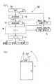
図1は、ドアの正面を示し、ドア枠10に左側がヒンジを介して回動自在に連結され、後方に開く扉1が嵌め込まれている。扉1の上部の図示左側(ヒンジ側)と、ドア枠10の上部材11との間には、ドアクローザー2が装着されている。ドアクローザー2の下方には、本発明の自動ドア開閉装置3が近接して取り付けてある。自動ドア開閉装置3とドアクローザー2との間は、カップリング12により連結されている。
【0015】
ドアクローザー2は公知の構成を有し、横長で偏平な箱状ケーシング21を備えた本体22が、扉1のヒンジ側の上部に4本のビス1Aにより水平に締結されている。ケーシング21の中央よりややヒンジよりには、上下両端部23、24を突き出した回動軸25が設けられ、上下両端部23、24には、カップリング12を構成する4角凸部13、14が突設されている。この構造により、同一型式のドアクローザー2を左開きのドアと右開きのドアとに上下逆転して装着できるようになっている。
【0016】
回動軸25は、ケーシング21内に設けられたバネおよび油圧による減衰手段(いずれも図示せず)により、扉1が開閉する動作を減衰するとともに、開動作に伴いバネを圧縮し、該バネのバネ荷重により扉1が閉じる方向の付勢力(位置エネルギー)が蓄積されるようになっている。
【0017】
回動軸25の上端部23には、扉側アーム26の基端2Aが4角凸部13に嵌合して連結されており、扉側アーム26は回動軸25と一体的に回動するようになっている。ドア枠10の上部材11にはブラケット27が締結されており、ブラケット27には固定側アーム28の基端2Bが平面内で回動自在に連結されている。扉側アーム26の先端と固定側アーム28の先端とは、支点29により回動自在に連結されている。
【0018】
自動ドア開閉装置3は、図2〜図4に示す如く、ケーシング21と略同一幅を有し、横長で偏平な箱状のハウジング30を備えている。この実施例では、ハウジング30は、ドアクローザー2の締結と同時に4本のビス1Aで、扉1に締結される矩形の基盤31を有する。基盤31の上半にはケーシング21が4本のビス1Aで扉1に締結されており、基盤31の下半にはハウジング30が4本のビス1B(図10に示す)で基盤31の表面に締結されている。
【0019】
ハウジング30は、湾曲した一連の前面および左右側面板32と、平板である天板33および底板34とからなり、背面は開放した構造をしている。ハウジング30の中央よりやや左側の回動軸25との対応位置には天板33および底板34に丸穴2C、2Dが開けられており、両端面4A、4Bを天板33および底板34から露出した状態で駆動軸4が垂直方向に取り付けられている。
【0020】
両端面4A、4Bには、4角凸部13、14に嵌合する4角凹部15、16が設けられ、カップリング12が構成されている。これにより、自動ドア開閉装置3は、図1に示す右開きドアに装着する型式のハウジング30を、上下逆転して図5に示す左開きドアのドアクローザー2(上下逆転して扉1に締結されている)の本体22の下に装着することができる。
【0021】
図6に示す如く、駆動軸4は、上部にキー溝51を有する筒状の外軸5内に回動自在に嵌め込まれている。図7に示す如く、駆動軸4には中間よりやや下位に欠落部41が形成されている。欠落部41は、円弧である底面42、平行した側面43、44、および二等辺直角三角形状の頂面45、46からなる小断面積の5角柱状部47で連結されている。
【0022】
外軸5の下部には、手動による扉1の回動範囲(駆動軸4と外軸5との相対回動範囲)を、180度に規制する自由回動範囲規制機構40が設けられている。手動可能な自由回動範囲規制機構40は、5角柱状部47と、ストッパーとしての帯板52とからなる。帯板52は、外軸5の軸心に対して直交方向(接線方向)で軸心から偏心した位置に貫通して設けたスリット5S、5Sに挿通され、ビス53で外軸5に固定されている。
【0023】
外軸5の上部には、電動(モーター)による扉1の回動範囲である外軸5の自動回動範囲を約90度に規制する自動回動範囲規制機構50が設けられている。自動回動範囲規制機構50は、キー溝51に差し込まれたキーにより外軸5に固定され4分円状の扇型ギア54と、ハウジング30の基盤31とから構成されている。扇型ギア54は、直交する一側辺55および他側辺56を有し、一側辺55が基盤31に当接する位置ではドアが閉じ、他側辺56が基盤31に当接する位置ではドアが90度開放している。
【0024】
ハウジング30の外軸5の側方(図2に示す右側下部)には、モーター6が出力軸61を垂直方向に突き出した状態で設置されている。出力軸61の上端には出力ギア62が連結されている。出力ギア62と扇型ギア54(外軸5)との間には、減速機構60が伝動機構として設けられている。減速機構60は、外軸5とモーター6との間に、外軸5と同一レベルに設置した、支軸63〜65に大ギアおよび小ギア(図2および図3の破線参照)を取り付けた減速ギア列で構成されている。
【0025】
この実施例の如く、自由回動範囲規制機構40を駆動軸4に設けた5角柱状部47と、外軸5にスリット5S、5Sと、スリット5S、5Sに挿通して配した帯板52で構成し、自動回動範囲規制機構50を扇型ギア54と基盤31とで構成することにより、単純で加工が容易な部品の組合せで自由回動範囲規制機構40が形成でき、加工コストの低減と故障の発生の低減とが可能となる。また、外軸5、モーター6および減速機構60を、横に並設することにより、自動ドア開閉装置3の上下方向の寸法を小さくでき、ドアクローザー2の本体22の下に取り付けた場合に下方への出っ張りを最小限にすることが可能となる。
【0026】
モーター6の回転により、扇型ギア54が回動し、図8の(イ)に示す如く、直交する一側辺55または他側辺56が、ハウジング30の基盤31に当接する約90度の範囲で回動する。駆動軸4と外軸5とは、図8の(ロ)に示す一側面43が帯板52に当接した位置から、図8の(ハ)に示す頂点Pが帯板52に当接した位置を経て、図8の(ニ)に示す他側面44が帯板52に当接した位置まで、180度回動できるようになっている。
【0027】
自動ドア開閉装置3による扉1の開閉動作を説明する。モーター6には、ドア開スイッチ71およびドア閉スイッチ72と商業電源とを含む通電制御回路7が接続されている。ドアが閉じられた状態では、外軸5は、扇型ギア54の一側辺55が基盤31に当接している図8の(イ)に実線で示す位置にあり、扉1は手動で180度回動できる。
【0028】
ドア開スイッチ71を押すと、モーター6が回転して出力ギア62、減速機構60を介して扇型ギア54が右回動し、図8の(イ)に一点鎖線で示す90度回転した位置まで回動し、他側辺56が基盤31に当接して停止する。扇型ギア54の回動により外軸5が一体に回動し、駆動軸4は外軸5の回動に連動して図8の(イ)に一点鎖線で示す90度回転した位置まで回動する。
【0029】
カップリング12により駆動軸4に連結された回動軸25が回動し、扉側アーム26は回動軸25と一体に回動するため、固定側アーム28も連動して回動し扉1は90度開く。この状態で扉1は更に手動で開く方向に回動させることができる。
【0030】
回動軸25には、回動に伴いドアクローザー2内のバネに扉1を閉じる位置エネルギーが蓄積される。モーター6への通電量を調整することで、ドアクローザー2による閉扉方向のトルクと釣り合わせ、扉1の開度をたとえば90度に維持できる。なお、減速機構60内に傘歯車、ウォームギア等の逆駆動阻止手段を用いて、モーター6への通電を停止させる構成であってもよい。
【0031】
開いた扉1を閉じる際に、ドア閉スイッチ72を押すとモーター6が逆転する。ドアクローザー2(または手動)による閉扉速度がモーター6による閉扉速度より小さいときは、モーター6による補助を受けることなくドアクローザー2で設定された速度で閉扉される。
【0032】
逆にドアクローザー2(または手動)による閉扉速度がモーター6による閉扉速度より大きいときは、扉1はドアクローザー2内で圧縮されたバネの復帰力によりモーター6を加速しながら閉扉する。扉1は、ドアクローザー2内のダンパーで減衰された閉扉速度よりさらにゆっくりした閉扉速度で扉1が閉じる。いずれの場合も閉扉速度が低速度に維持され安全が保たれている。
【0033】
なお、モーター6の起動スイッチは、赤外線または超音波を利用した遠隔操作装置であってもよく、ドアを通過するか又は接近した人を検知して作動するセンサであってもよい。また、扉の把手に接触したことを検出するセンサも使用できる。
【0034】
図9は、第2実施例を示す。この実施例では、基盤31をビス1Aで扉1に締結するためのビス穴1Cを上下に長い長穴としている。ビス1Aおよびビス穴1Cは変位機構を成し、ビス1Aを緩めて自動ドア開閉装置3を下方に変位させ、再びビス1Aを締めることにより、カップリング12の連結を解除することができる。停電などで、自動ドア開閉装置3の運転ができない時、あるいは自動ドア開閉装置3が故障した時などに、ドアクローザー2のみによるドアの開閉を容易に行うことができる。
【0035】
図10は、第3実施例を示す。この実施例では、4本のビス1Bのビス穴1Dを上下に長い長穴としている。ビス1Bおよびビス穴1Dは変位機構を成し、ビス1Bを緩めて自動ドア開閉装置3を下方に変位させることにより、カップリング12の連結を解除することができる。
【0036】
図11の(イ)、(ロ)は本発明の第4実施例として扉制御手段80および扉1の態様を示す。第4実施例では、安全性の観点から扉制御手段80に基づいて扉1の開閉制御を行う。起動スイッチ(図示せず)の信号が信号識別部76に送られると、電源70が閉じられて扉1に対する閉信号、半開信号および全開信号に応じて信号識別部76が通電制御部77に指示信号を送る。中央演算部75では閉信号、半開信号あるいは全開信号のうちいずれであっても、常に閉信号を優先的に適用し、扉1を閉鎖位置(原点基準位置)に回動するようにモーター6を通電する。扉1が閉鎖位置にあることを閉鎖位置検出部73により検出すると、検出信号を通電制御部77に送って中央演算部75によりモーター6を閉信号、半開信号および全開信号に応じて制御する。
【0037】
この場合、扉1が閉鎖位置にあることを検出済みなので、閉信号では扉閉鎖モードとしてモーター6を無通電にして扉1の閉鎖動作を終える。この後、扉1の開方向の作動は操作信号に応じて行なわれ、半開信号では、扉半開モードとしてモーター6に通電して扉1を閉鎖位置から45度の角度だけ回転させる。全開信号では、扉全開モードとしてモーター6に通電して扉1を閉鎖位置から90度の角度だけ回転させる。
【0038】
閉鎖位置検出部73により、扉1が閉鎖位置にあることが検出されない場合、無検出信号を過電流検出部74に送ってモーター6への過電流の有無を検出する。過電流が検出されない場合、信号識別部76に戻って閉信号、半開信号および全開信号を識別し、上記と同様な手順を繰り返す。過電流検出部74によりモーター6への過電流が検出される場合、作動不良などの異常時として電源70を切ってモーター6を停止させる。この後、扉1の開閉動作を再開するには、電源70を再投入する必要がある。
【0039】
第4実施例では、閉信号、半開信号あるいは全開信号のうちいずれであっても、扉1が閉鎖位置にあることを確認した後、閉鎖位置を原点基準位置としてモーター6を制御する。このため、扉1は使用者および自動ドア開閉装置に対して常に安全側に制御されることとなり、扉1が僅かに開いた状態からモーター6が半開や全開方向に通電駆動されることがない。これにより、扉1がモーター6により開方向に無理に強制駆動されることがなく使用上の安全性が確保される。
【図面の簡単な説明】
【図1】自動ドア開閉装置およびドアクローザーの正面図である。
【図2】ドアクローザーの正面図である。
【図3】ドアクローザーの平面図である。
【図4】ドアクローザーの右側面図である。
【図5】自動ドア開閉装置を装着した左開きドアの正面図である。
【図6】駆動軸と外軸との組付け体の斜視図である。
【図7】駆動軸と外軸との組付け図である。
【図8】作動説明のための駆動軸と外軸との組付け体の平面図である。
【図9】自動ドア開閉装置の第2実施例の正面図である。
【図10】自動ドア開閉装置の第3実施例の正面図である。
【図11】(イ)は第4実施例の扉制御手段に係るブロック図、(ロ)は扉の態様を示す概略図である。
【符号の説明】
1 扉
1A、1Bビス(変位機構)
1C、1Dビス穴(変位機構)
12 カップリング
2 ドアクローザー
21 ケーシング
22 ドアクローザーの本体
25 回動軸
26 扉側アーム
28 固定側アーム
3 自動ドア開閉装置
30 ハウジング
31 基盤
4 駆動軸
40 自由回動範囲規制機構
5 外軸
50 自動回動範囲規制機構
52 帯板
54 扇型ギア
6 モーター
60 減速機構(伝動機構)
61 出力軸
7 通電制御回路[0001]
BACKGROUND OF THE INVENTION
The present invention relates to an automatic door opening and closing device using a door closer mounted between a door and a fixing member such as a door frame.
[0002]
[Prior art]
A door that opens and closes an opening such as an entrance is hinged to a door frame or a wall (fixing member) on either the left or right side of the door and is attached rotatably. Between the door and the fixing member, a door closer for automatically closing the opened door is mounted on the upper part of the door.
[0003]
The door closer includes a main body having a pivot shaft with both ends protruding vertically, a door-side arm connected to the upper end of the pivot shaft, and one end rotating to the tip of the door-side arm. A stationary arm that is movably coupled and has the other end pivotally coupled to the stationary member. The main body includes a spring in the horizontally long casing that attenuates the rotation speed by hydraulic pressure on the rotation shaft and accumulates potential energy in the door closing direction in conjunction with the opening of the door. The casing is fastened from the fulcrum side at the upper part of the door, and the fixed arm is connected to a bracket whose other end is fastened to a fixing member in the vicinity of the door and rotates in a horizontal plane.
[0004]
[Problems to be solved by the invention]
The present applicant has proposed an automatic door opening / closing device that can be easily mounted on a door with a door closer in Japanese Patent Laid-Open No. 2000-96915. This automatic door opening and closing device is configured to open and close the door with a motor having an output shaft concentric with the rotation shaft under the door closer. For this reason, the downward bulge becomes large, and there is a problem that the appearance deteriorates and gets in the way.
[0005]
The object of the present invention is to make effective use of a door closer so that it can be easily mounted on a conventional door with a door closer, the vertical dimension can be reduced, the appearance and downward bulge can be reduced, and the same automatic An object of the present invention is to provide an automatic door opening and closing devicecapable of fitting the door opening and closing device to the left and right doors .
[0006]
The object of the present invention is to provide a free rotation range limiting means for the drive shaft relative to the outer shaft, and a rotation range limiting mechanism for the fan-shaped gear fixed to the outer shaft. The present invention provides an automatic door opening and closing device that can reduce the cost and failure.
[0007]
The purpose of the invention described in請 Motomeko3, with a simple structure and working, only door closer, such as during a power failure is to provide an automatic door openerscan be changed to manual opening and closing acting.
[0008]
[Means for Solving the Problems]
The present invention includes a main body in which a rotating shaft with both ends exposed vertically is provided in a casing fastened to a door, and a biasing / damping means for the rotating shaft by a spring and hydraulic pressure is incorporated, and a base end Is coupled to one end of the pivot shaft and integrally pivots, a base end is pivotally coupled to a fixed member, and a distal end is pivotally coupled to the distal end of the door side arm. An automatic door opening and closing device for a door provided with a door closer that accumulates potential energy in the closing direction as the door opens,
A housing mounted close to or below the casing; a drive shaft provided with a coupling to the lower end or upper end of the rotating shaft at the upper end or lower end; a motor, an output shaft of the motor, and the drive A transmission mechanism between the shaft and an energization control circuit for the motor, the motorbeing attached to a side of the drive shaft in the housing, the housing having substantially the same width as the casing It has a horizontally long box shape, and the door is opened and closed by turning the turning shaft by energization control to the motor.
[0009]
[Operation and effect of the invention]
In this invention, the coupling with theupper andlower sides of the rotating shaft of the door closer is providedabove and below the drive shaft. For this reason, one automatic door opening and closing device can be sharedby the left-opening door and the right-opening door.That is, the housing has a horizontally long box shape that is substantially the same width as the casing, and can be mounted on both the left-opening door and the right-opening door by turning the housing upside down. In this configuration, the housing can be formed flat, and the appearance is excellent and the safety is high.
[0010]
In the invention according to
[0011]
In this configuration, a drive shaft connected to a rotation shaft is disposed on a horizontally long housing on the lower surface of the casing of the door closer, and is transmitted by a motor and a gear train provided on the side. For this reason, the structure of the means for limiting the free rotation range of the drive shaft is simple and easy to process, and failure is unlikely to occur.
[0013]
In thethird aspect of the invention, when the automatic door opening / closing device is moved downward during a power failure, the coupling is released and only the door closer is operated, so that the manual opening / closing is restored. Thereby, it can return to manual easilyat the time of a power failure or when an automatic door opening and closing device breaks down.
[0014]
DETAILED DESCRIPTION OF THE INVENTION
FIG. 1 shows the front of the door, and the
[0015]
The door closer 2 has a known configuration, and a
[0016]
The rotating
[0017]
The
[0018]
As shown in FIGS. 2 to 4, the automatic door opening /
[0019]
The
[0020]
The both
[0021]
As shown in FIG. 6, the
[0022]
Below the
[0023]
At the upper part of the
[0024]
The side of the
[0025]
As in this embodiment, a
[0026]
The fan-shaped
[0027]
The opening / closing operation | movement of the
[0028]
When the
[0029]
Since the
[0030]
In the
[0031]
When the
[0032]
Conversely, when the closing speed of the door closer 2 (or manually) is higher than the closing speed of the
[0033]
In addition, the start switch of the
[0034]
FIG. 9 shows a second embodiment. In this embodiment, a
[0035]
FIG. 10 shows a third embodiment. In this embodiment, the screw holes 1D of the four
[0036]
11 (a) and 11 (b) show aspects of the door control means 80 and the
[0037]
In this case, since it is detected that the
[0038]
If the closed
[0039]
In the fourth embodiment, the
[Brief description of the drawings]
FIG. 1 is a front view of an automatic door opening and closing device and a door closer.
FIG. 2 is a front view of the door closer.
FIG. 3 is a plan view of the door closer.
FIG. 4 is a right side view of the door closer.
FIG. 5 is a front view of a left opening door equipped with an automatic door opening and closing device.
FIG. 6 is a perspective view of an assembly of a drive shaft and an outer shaft.
FIG. 7 is an assembly diagram of a drive shaft and an outer shaft.
FIG. 8 is a plan view of an assembly of a drive shaft and an outer shaft for explanation of operation.
FIG. 9 is a front view of a second embodiment of the automatic door opening and closing device.
FIG. 10 is a front view of a third embodiment of the automatic door opening and closing device.
FIGS. 11A and 11B are block diagrams according to the door control means of the fourth embodiment, and FIG. 11B is a schematic view showing a mode of the door.
[Explanation of symbols]
1 door
1A, 1Bscrew (displacement mechanism)
1C, 1Dscrew hole (displacement mechanism)
DESCRIPTION OF
61 Output shaft 7 Energization control circuit
Claims (3)
Translated fromJapanese前記ケーシングに下または上に近接して装着されるハウジングと、上端または下端に前記回動軸の下端または上端へのカップリングが設けられた駆動軸と、モーターおよび該モーターの出力軸と前記駆動軸との間の伝動機構と、前記モーターへの通電制御回路とからなり、前記モーターは、前記ハウジング内の前記駆動軸の側方に取り付けられており、前記ハウジングは前記ケーシングと略同一幅の横長箱状を呈し、前記モーターへの通電制御により前記回動軸を回動させてドアを開閉させることを特徴とする自動ドア開閉装置。A casing that is fastened to the door is provided with a rotating shaft with both ends exposed up and down, a main body in which a biasing and damping means for the rotating shaft by a spring and hydraulic pressure is incorporated, and a base end that rotates A door-side arm connected to one end of the shaft and rotating integrally, and a fixed-side arm having a base end rotatably connected to a fixing member and a distal end rotatably connected to the distal end of the door-side arm An automatic door opening and closing device for a door with a door closer that accumulates potential energy in the closing direction as the door opens.
A housing mounted close to or below the casing; a drive shaft provided with a coupling to the lower end or upper end of the rotating shaft at the upper end or lower end; a motor, an output shaft of the motor, and the drive A transmission mechanism between the shaft and an energization control circuit for the motor, the motorbeing attached to a side of the drive shaft in the housing, the housing having substantially the same width as the casing An automatic door opening and closing device having ahorizontally long box shape, wherein the door is opened and closed by rotating the rotation shaft by energization control to the motor.
Priority Applications (1)
| Application Number | Priority Date | Filing Date | Title |
|---|---|---|---|
| JP2002211605AJP3990604B2 (en) | 2001-07-24 | 2002-07-19 | Automatic door opener |
Applications Claiming Priority (3)
| Application Number | Priority Date | Filing Date | Title |
|---|---|---|---|
| JP2001222568 | 2001-07-24 | ||
| JP2001-222568 | 2001-07-24 | ||
| JP2002211605AJP3990604B2 (en) | 2001-07-24 | 2002-07-19 | Automatic door opener |
Publications (2)
| Publication Number | Publication Date |
|---|---|
| JP2003106047A JP2003106047A (en) | 2003-04-09 |
| JP3990604B2true JP3990604B2 (en) | 2007-10-17 |
Family
ID=26619151
Family Applications (1)
| Application Number | Title | Priority Date | Filing Date |
|---|---|---|---|
| JP2002211605AExpired - Fee RelatedJP3990604B2 (en) | 2001-07-24 | 2002-07-19 | Automatic door opener |
Country Status (1)
| Country | Link |
|---|---|
| JP (1) | JP3990604B2 (en) |
Families Citing this family (3)
| Publication number | Priority date | Publication date | Assignee | Title |
|---|---|---|---|---|
| JP5791273B2 (en)* | 2010-12-17 | 2015-10-07 | 文化シヤッター株式会社 | Switchgear |
| JP7051558B2 (en)* | 2018-04-26 | 2022-04-11 | リョービ株式会社 | Electric door closer |
| CN109862773A (en)* | 2019-03-29 | 2019-06-07 | 贵州华斯特能源科技有限公司 | A kind of cabinet with magnetic field shielding function |
- 2002
- 2002-07-19JPJP2002211605Apatent/JP3990604B2/ennot_activeExpired - Fee Related
Also Published As
| Publication number | Publication date |
|---|---|
| JP2003106047A (en) | 2003-04-09 |
Similar Documents
| Publication | Publication Date | Title |
|---|---|---|
| US5930954A (en) | Remote control door operating device | |
| US5634296A (en) | Remote control door operating device | |
| US6283535B1 (en) | Apparatus for driving vehicle door to open and close | |
| US5752344A (en) | Swing gate operator | |
| US5507120A (en) | Track driven power door operator | |
| JP2006145708A5 (en) | ||
| MXPA06014824A (en) | Door operator. | |
| US11454059B2 (en) | Vehicle side door opening/closing device | |
| JP3990604B2 (en) | Automatic door opener | |
| JP3982391B2 (en) | Drive device | |
| KR200376430Y1 (en) | A slide door electric driving apparatus | |
| JP4024398B2 (en) | Automatic door opener | |
| KR102754997B1 (en) | Digital door closer | |
| KR102015902B1 (en) | entrance door automatic switching unit | |
| JP4295006B2 (en) | Back door opening and closing system | |
| JP4071076B2 (en) | Automatic door opener | |
| JP3217134B2 (en) | Window locking device | |
| KR100279730B1 (en) | Safety door closers | |
| JP3895632B2 (en) | Automatic door opener | |
| JP2000096913A (en) | Vehicle door opening and closing device | |
| JP3807936B2 (en) | Opening and closing body closing device | |
| JPH0442473Y2 (en) | ||
| JP2521856Y2 (en) | Folding door | |
| JP3646438B2 (en) | Flip-up gate | |
| CN111997477B (en) | Automatic door opener |
Legal Events
| Date | Code | Title | Description |
|---|---|---|---|
| A621 | Written request for application examination | Free format text:JAPANESE INTERMEDIATE CODE: A621 Effective date:20050607 | |
| A977 | Report on retrieval | Free format text:JAPANESE INTERMEDIATE CODE: A971007 Effective date:20060901 | |
| A131 | Notification of reasons for refusal | Free format text:JAPANESE INTERMEDIATE CODE: A131 Effective date:20070424 | |
| A521 | Request for written amendment filed | Free format text:JAPANESE INTERMEDIATE CODE: A523 Effective date:20070622 | |
| TRDD | Decision of grant or rejection written | ||
| A01 | Written decision to grant a patent or to grant a registration (utility model) | Free format text:JAPANESE INTERMEDIATE CODE: A01 Effective date:20070717 | |
| A61 | First payment of annual fees (during grant procedure) | Free format text:JAPANESE INTERMEDIATE CODE: A61 Effective date:20070720 | |
| FPAY | Renewal fee payment (event date is renewal date of database) | Free format text:PAYMENT UNTIL: 20100727 Year of fee payment:3 | |
| R150 | Certificate of patent or registration of utility model | Free format text:JAPANESE INTERMEDIATE CODE: R150 | |
| FPAY | Renewal fee payment (event date is renewal date of database) | Free format text:PAYMENT UNTIL: 20110727 Year of fee payment:4 | |
| FPAY | Renewal fee payment (event date is renewal date of database) | Free format text:PAYMENT UNTIL: 20120727 Year of fee payment:5 | |
| FPAY | Renewal fee payment (event date is renewal date of database) | Free format text:PAYMENT UNTIL: 20120727 Year of fee payment:5 | |
| FPAY | Renewal fee payment (event date is renewal date of database) | Free format text:PAYMENT UNTIL: 20130727 Year of fee payment:6 | |
| R250 | Receipt of annual fees | Free format text:JAPANESE INTERMEDIATE CODE: R250 | |
| LAPS | Cancellation because of no payment of annual fees |