JP3989030B2 - Ultrasonic incision coagulator - Google Patents
Ultrasonic incision coagulatorDownload PDFInfo
- Publication number
- JP3989030B2 JP3989030B2JP08146695AJP8146695AJP3989030B2JP 3989030 B2JP3989030 B2JP 3989030B2JP 08146695 AJP08146695 AJP 08146695AJP 8146695 AJP8146695 AJP 8146695AJP 3989030 B2JP3989030 B2JP 3989030B2
- Authority
- JP
- Japan
- Prior art keywords
- sheath
- treatment
- ultrasonic
- distal end
- probe
- Prior art date
- Legal status (The legal status is an assumption and is not a legal conclusion. Google has not performed a legal analysis and makes no representation as to the accuracy of the status listed.)
- Expired - Fee Related
Links
- 230000005540biological transmissionEffects0.000claimsdescription40
- 238000003780insertionMethods0.000claimsdescription33
- 230000037431insertionEffects0.000claimsdescription33
- 230000015271coagulationEffects0.000claimsdescription26
- 238000005345coagulationMethods0.000claimsdescription26
- 230000009471actionEffects0.000claimsdescription3
- 238000002224dissectionMethods0.000claimsdescription2
- 238000011282treatmentMethods0.000description93
- 239000000523sampleSubstances0.000description49
- 230000007246mechanismEffects0.000description15
- 238000000034methodMethods0.000description14
- 230000008878couplingEffects0.000description13
- 238000010168coupling processMethods0.000description13
- 238000005859coupling reactionMethods0.000description13
- 230000002093peripheral effectEffects0.000description11
- 239000000463materialSubstances0.000description10
- 239000004810polytetrafluoroethyleneSubstances0.000description8
- 229920001343polytetrafluoroethylenePolymers0.000description8
- XLYOFNOQVPJJNP-UHFFFAOYSA-NwaterSubstancesOXLYOFNOQVPJJNP-UHFFFAOYSA-N0.000description7
- 210000000078clawAnatomy0.000description6
- 238000005304joiningMethods0.000description6
- 230000001954sterilising effectEffects0.000description6
- 238000004659sterilization and disinfectionMethods0.000description6
- 238000004140cleaningMethods0.000description5
- 238000009210therapy by ultrasoundMethods0.000description5
- 230000001681protective effectEffects0.000description4
- 230000001112coagulating effectEffects0.000description3
- 238000010586diagramMethods0.000description3
- 230000000694effectsEffects0.000description3
- 239000011810insulating materialSubstances0.000description3
- 239000002184metalSubstances0.000description3
- 230000008569processEffects0.000description3
- 239000000919ceramicSubstances0.000description2
- 239000012777electrically insulating materialSubstances0.000description2
- 238000002674endoscopic surgeryMethods0.000description2
- 230000020169heat generationEffects0.000description2
- 230000000149penetrating effectEffects0.000description2
- 229920002492poly(sulfone)Polymers0.000description2
- 230000008439repair processEffects0.000description2
- 239000002699waste materialSubstances0.000description2
- 238000003466weldingMethods0.000description2
- 239000004696Poly ether ether ketoneSubstances0.000description1
- 239000011358absorbing materialSubstances0.000description1
- 229910045601alloyInorganic materials0.000description1
- 239000000956alloySubstances0.000description1
- 238000005452bendingMethods0.000description1
- JUPQTSLXMOCDHR-UHFFFAOYSA-Nbenzene-1,4-diol;bis(4-fluorophenyl)methanoneChemical compoundOC1=CC=C(O)C=C1.C1=CC(F)=CC=C1C(=O)C1=CC=C(F)C=C1JUPQTSLXMOCDHR-UHFFFAOYSA-N0.000description1
- 230000000740bleeding effectEffects0.000description1
- 239000008280bloodSubstances0.000description1
- 210000004369bloodAnatomy0.000description1
- 238000006243chemical reactionMethods0.000description1
- 238000004925denaturationMethods0.000description1
- 230000036425denaturationEffects0.000description1
- 238000010292electrical insulationMethods0.000description1
- 239000012530fluidSubstances0.000description1
- KHYBPSFKEHXSLX-UHFFFAOYSA-NiminotitaniumChemical compound[Ti]=NKHYBPSFKEHXSLX-UHFFFAOYSA-N0.000description1
- 238000000465mouldingMethods0.000description1
- 229910001000nickel titaniumInorganic materials0.000description1
- 238000011369optimal treatmentMethods0.000description1
- 230000001151other effectEffects0.000description1
- 238000010422paintingMethods0.000description1
- 229920002530polyetherether ketonePolymers0.000description1
- 238000003825pressingMethods0.000description1
- 102000004169proteins and genesHuman genes0.000description1
- 108090000623proteins and genesProteins0.000description1
- 239000011347resinSubstances0.000description1
- 229920005989resinPolymers0.000description1
- 238000007789sealingMethods0.000description1
- 238000005406washingMethods0.000description1
Images


Classifications
- A—HUMAN NECESSITIES
- A61—MEDICAL OR VETERINARY SCIENCE; HYGIENE
- A61B—DIAGNOSIS; SURGERY; IDENTIFICATION
- A61B17/00—Surgical instruments, devices or methods
- A61B17/32—Surgical cutting instruments
- A61B17/320068—Surgical cutting instruments using mechanical vibrations, e.g. ultrasonic
- A61B17/320092—Surgical cutting instruments using mechanical vibrations, e.g. ultrasonic with additional movable means for clamping or cutting tissue, e.g. with a pivoting jaw
Landscapes
- Surgical Instruments (AREA)
Description
Translated fromJapanese【0001】
【産業上の利用分野】
本発明は超音波を利用して切開或いは凝固等の処置を行う超音波切開凝固装置に関する。
【0002】
【従来の技術】
従来、超音波振動を用いて生体組織に対して処置を行う事は一般的に知られており、その中でも生体組織を吸着あるいは把持する等、超音波処置具に固定して処理を行うものがあった。
【0003】
例えば特願昭62−127042では結石を把持して超音波振動により破砕する様になっており、特願平1−232944では生体組織を把持鉗子で把持して固定し、超音波振動するプローブで切開する様になっていた。又、特願平1−232945では生体組織を吸着させて固定し、超音波振動するメスにより切開する様になっていた。
【0004】
更に特願平1−232948では切除鉗子に超音波振動を加える事により生体組織の切除を効率的に行える様になっており、特願平1−232949では特願平1−232944と同様に把持手段により生体組織を固定し、超音波振動を加えた処置部材により生体組織に処置を加える様になっており、USP5,322,055ではプローブの上部に把持部材を設け、プローブと把持部材により生体組織を固定して処置を行う様になっていた。これらは通常の外科鉗子の様に生体組織を把持して処置が行えるので、一般にプローブ単体で処置を行う場合よりも良好な処置が行い易かった。
【0005】
又、USP4,988,334や特願平2−203573等の様に一般に超音波吸引装置と呼ばれるものには、シースがハンドピースに対して分解及び組立可能となっているものもあったが、前述の様な把持部材を有するものの中にはこの様なものは無く、特に分解及び組立が出来るものは無かった為、洗浄及び滅菌工程時には細心の注意を持って各部を洗浄及び滅菌する必要があり、非常に手間が掛かっていた。或いはこの手間を省くために使い捨てとする場合もあったが、医療量削減や汚染された廃棄物の削減、資源の節約といった点に問題があった。
【0006】
又、どこか一部でも破損すると全体を修理するか交換する必要があった。更には各部を何種類か用意しておき、処置に最適な組み合わせで使用する事も出来ず、必要な種類だけ超音波処置具を用意する必要があった。
【0007】
この様に超音波処置具で生体組織を把持出来る手段の備わっているものについては、取り扱う者の人手や時間あるいは費用の問題があり、その負担は結果的に医療費の高騰原因の一つともなる可能性があった。
【0008】
又、従来、内視鏡下外科手術において使用される処置具は一般的に生体組織に対して処置を行う処置部が、処置部を生体内に挿入する為の挿入部であるシースの遠位端に設けられており、挿入部の近位端に処置部を操作する為の操作手段が設けられていた。
【0009】
これらの内視鏡下外科手術用の処置具において、DE7330291や特願平6−179049の様に挿入部、処置部、操作部等に各部を分解及び組立可能としたものが知られている。そしてこの構造により洗浄及び滅菌工程においては、より確実な各部の洗浄及び滅菌が可能となる他、例えば処置部のみが破損した場合等にその部分だけを交換出来る、あるいは各部をそれぞれ何種類か用意しておく事により、色々な部品を組み合わせて処置に最適な処置具を用意出来る等のメリットがある為に、前述の様な問題点をある程度解決してはいた。
【0010】
しかし、この様な処置具は一般に生体組織を切開、凝固する際に高周波電流のみを用いる事が出来た。ところが高周波電流は生体組織のタンパク変性する範囲が広いので場合によっては過剰な処置を行ってしまう原因ともなっており、出来れば超音波振動と併用し状況に応じて使い分ける事が望ましかったが、この様な処置具単体では不可能であった。
【0011】
【発明が解決しようとする課題】
前述の様な超音波処置具において把持部材を有するものには特に分解及び組立が出来るものは無かった為、洗浄及び滅菌工程時には細心の注意を持って各部を洗浄及び滅菌する必要があり、非常に手間が掛かっていた。或いはこの手間を省くために使い捨てとする場合もあったが、医療量削減や汚染された廃棄物の削減、資源の節約といった点に問題があった。
【0012】
又、どこか一部でも破損すると全体を修理するか交換する必要があった。更には各部を何種類か用意しておき、処置に最適な組み合わせで使用する事も出来ず、必要な種類だけ超音波処置具を用意する必要があった。
その為に取り扱う者の人手や時間あるいは費用の問題があり、その負担は結果的に医療費の高騰原因の一つともなる可能性があった。
【0013】
本発明は上述した点に鑑みてなされたもので、手間をかけないで確実に洗浄及び滅菌ができ、一部の交換等を容易に行うことのできる超音波切開凝固装置を提供することを目的とする。
【0014】
【課題を解決するための手段】
本発明の超音波切開凝固装置は、被検体に挿入可能な挿入部を構成するシースと、
前記被検体を処置するための超音波振動を発生する超音波振動子と、
前記超音波振動を前記被検体に伝達可能に前記超音波振動子と接続し、前記シースに挿入される振動伝達部材と、
前記振動伝達部材の遠位端部との間で前記被検体の生体組織を回動作用により把持するための把持部材と、
前記シース内に挿入可能になされた長軸状部材であって、遠位端部において前記把持部材と連結し、操作手段の操作に応じて当該シース内において軸方向に進退移動することにより前記操作手段の動きを前記把持部材に伝達する伝達部材と、
前記シース内に挿入可能になされた、前記伝達部材を軸方向に進退自在に覆うカバー部材であって、前記シースに挿入された際に当該シースに対して軸方向に着脱可能に固定するための固定手段を備え、かつ、遠位端部において前記把持部材を枢支ピンにより回動自在に支持する支持部材と、
前記把持部材、前記伝達部材及び前記支持部材とを一体的に構成して成した鉗子ユニットの少なくとも近位端側を挿入可能とする、前記シース内に形成された鉗子ユニット挿入チャンネルと、
を具備し、
前記鉗子ユニットの近位端側を前記鉗子ユニット挿入チャンネルの遠位端側より挿入し、当該鉗子ユニットを構成する前記支持部材を前記固定手段により前記シースに対して軸方向に着脱可能に固定する。
【0015】
【実施例】
(第1実施例)
図1〜図9は本発明の第1実施例に係り、図1は本発明の第1実施例の全体図、図2は処置部と挿入部の構造を示す断面図、図3は図2のD1−D2−D3−D4線断面図、図4は図2の正面から見た処置部の正面図、図5は図2のA−A′〜G−G′線断面図、図6は操作手段を示す平面図、図7は操作手段及びその一部を拡大して示す部分断面図、図8は図7(A)のH−H′線及びI−I′線断面図、図9は図7(A)のJ−J′〜M−M′線断面図である。
【0016】
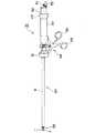
図1に示すように本発明の第1実施例の超音波切開凝固装置31は遠位端(先端)に処置を行う処置部33を設けた挿入部57と、この挿入部57の近位端(後端)に形成され、処置部33を操作する操作手段34とを有する。この挿入部57は生体内に挿入できるように細長のシース9で挿入部外套管が形成されている。
【0017】
操作手段34の上部の近位端側には、前記シース9よりも太い径のシース22が設けられ、このシース22の近位端に処置部33に対し、切開及び凝固の処置の為の超音波振動を供給する超音波振動子50(図7参照)を内蔵した振動子ユニットとしてのハンドピース32が設けてある。
【0018】
図2に示すように挿入部57を構成するシース9は、このシース9で保護された例えば上下に2つ独立した管路を有し、その上部側の管路内には切開及び凝固の処置を行う処置具としての鉗子ユニット58が挿通され、下部側の管路内にはハンドピース32内の超音波振動子50からの超音波振動を伝達する振動伝達部材としてのプローブ8と、このプローブ8の遠位端に螺合により着脱自在で取り付けた先端部材7とが挿通されている。
処置部33及び挿入部57は図2〜図5に示す様な構造になっている。
【0019】
鉗子ユニット58はパイプ状の外管部材内に、操作手段34による操作力を伝達する進退自在な略円柱形状の可動部材を挿通し、さらにプローブ8の遠位端に設けた先端部材7との間で生体組織を把持したり開放したりする把持部材1が、鉗子ユニット58の遠位端の可動部3にネジ2により接合されている。つまり、図4に示すように把持部材1の下端と先端部材7の上端とは略平面状であり、両平面で生体組織を把持及び開放できるようにしている。
なお、図3に示すように把持部材1の下端側の面には横方向に延びる横溝を設けて組織を確実に把持して凝固易くする凝固溝61が形成されている。
【0020】
図2及び図3に示すように上記可動部3は鉗子ユニット58の伝達部材としての第1の伝達部材5の遠位端側にピン35を中心に回転自在に支持され、かつ長孔に係入したピン36の進退移動によりピン35を中心として回動される。
【0021】
この第1の伝達部材5の近位端側には連結部材41が螺着されており、この連結部材41には第2の伝達部材10の遠位端が螺着されており、さらにこの第2の伝達部材10の近位端側は挿入部57を形成するシース9の近位端から近位側(後方)に突出し、この突出する近位端には係合部材42の遠位端が螺着により接続されている。つまり、鉗子ユニット58を構成する第1の伝達部材5は螺着によりその近位側の伝達部材10及びさらにその近位側の係合部材42と(分解及び組立可能に)連結されている。
【0022】
この係合部材42の近位端には球状部43が形成されており、この球状部43は図1及び図7に示す操作手段34を構成する可動操作ハンドル30の上部側の係止機構で挿入部57の軸方向に進退移動可能に保持され、可動操作ハンドル30の開閉操作により係合部材42、第2の伝達部材10及び第1の伝達部材5が進退駆動され、前述の様に可動部3を開閉させる事が出来る。
【0023】
鉗子ユニット58の外管側部材を形成するシース11はその外側のシース10と共に、その近位端はノブ12の内側の位置で結合部材13を介してパイプ14と結合(連結)され、このパイブ14は操作手段34における固定側操作部材となる固定操作ハンドル29に取付られる。
【0024】
把持部材1、ネジ2は後述する様に先端部材7に高周波電流を流して処置を行う場合には樹脂材等の絶縁材料で成形されるが、その他の場合には金属等で成形しても良い。
【0025】
図2及び図3に示すようにシース9における鉗子ユニット58が挿通される上部側の管路には略円筒形状の噛合部材37が挿通され、この噛合部材37の近位よりの内周面には半径内側に突出する突起部39(図2、図3、図5(F)参照)が設けてあり、この突起部39には先端カバー6の近位端に設けられているスナップフィット38により係合し、この先端カバー6のスナップフィット38を突起部39を越えて近位側に押し込むことにより両者を係合状態にして鉗子ユニット58をシース9内に固定(ロック)できるようにしている。そして、鉗子ユニット58をシース9の遠位側に強く引っ張る操作を行うことにより両者の係合を解いて分解、つまり鉗子ユニット58をシース9から取り外す事ができるようにしている。
【0026】
この時、把持部材1が少しでも開放されていると、それにより連結部材41の位置が前進して連結部材41の遠位端がスナップフィット38内部に進入するようにしている。そして、この侵入の為にスナップフィット38が内周方向に撓む事が出来ずに鉗子ユニット58をシース9から取り外す事が出来ない様になっている。
【0027】
即ち、鉗子ユニット58側を取り外す際には把持部材1が先端部材7に対して完全に閉鎖している必要があるので、実際の使用時に生体組織を把持している場合等のように完全の閉鎖状態に無い場合には鉗子ユニット58が脱落してしまう危険性が無く、安全性を確保して鉗子ユニット58をシース9から分解及び組立可能な構造にしている。
【0028】
又、この際、噛合部材37と先端カバー6との嵌合する部分を回転対称でない構造(例えば、先端カバー6の外周面に、噛合部材37が嵌合するように形成する段差面の遠位端の位置が周方向で異なるように形成する)にした回転防止機構40(図2、図3、図5(F)参照)により、鉗子ユニット58がシース9に対して回転する事を防止し、生体組織を把持した場合等において不用意に回転して操作性が低下するのを解消している。
噛合部材37の近位端はシース9の内側に介装されるシース11と連結されている。
【0029】
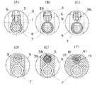
シース9の下部の管路には先端部材7と、この先端部材7の近位端に螺着されて超音波振動子50からの超音波振動を先端部材7に伝達するプローブ8が挿入されている。先端部材7の遠位端は上部側が図5(A)の様に平面となっており、把持部材1との間で生体組織を把持しやすい様になっている。この先端部材7の上部側の平面は図2及び図5(B),図5(C)に示すように把持部材1よりも近位側にまで形成され、それより近位側の断面形状は図5(D)〜図5(F)に示すように円形である。
【0030】
又、先端部材7の遠位端頂点は略錘状に成形されており、把持部材1よりも遠位側に突出しており、この部分で剥離操作を行う事が出来る。先端部材7はプローブ8の先端に対して螺合により着脱自在となっており、把持部材1も可動部3に対してネジ2により脱着自在となっているので、それぞれを自由に交換して処置に最適な形状の先端部材7と把持部材1を使用する事が出来る。
【0031】
図2に示すようにシース9の下部管路の遠位側開口部には、PTFEやセラミック等の耐熱性と超音波振動に対する耐性のある保護部材4が設けられており、これにより生体組織を把持した際に先端部材7に下方への曲げ反応が発生した場合等に、先端部材7とシース9が接触して破損する事を防止している。
【0032】
図6〜図9に操作手段34を示す。操作手段34は挿入部57の近位端に設けられており、シース9と結合部材13が接合されている。その結合部材13の外周にパイプ14の遠位端が接合されており、このパイプ14の遠位端外周にノブ12が嵌合し、ネジ44により結合(固定)されている。
【0033】
このネジ44を緩めるとノブ12はシース9の遠位端側に外すことができ、後述するようにシース9側(シース9、パイプ14、シース22)を操作手段34に対して分解でき、また組立することも可能な構成にしている。
【0034】
このパイプ14は固定操作ハンドル29の前後に分岐した上部にそれぞれ接合されている第1の軸受け15及び第2の軸受け19の内部を貫通しており、固定操作ハンドル29に固定される第1の軸受け15及び第2の軸受け19に対してパイプ14は回動自在に支持され、またパイプ14外周面と第1の軸受け15及び第2の軸受け19の内周面との少なくとも周方向に(この実施例では前後方向にも)摺動自在の摺動面にはOリング45と2つのOリング47が設けられており、パイプ14と軸受け15及び軸受け19との回動力量を調節可能にしている。
【0035】
従って、ノブ12をつかんで回動する操作を行うと、ノブ12と共にパイプ14は第1の軸受け15及び第2の軸受け19に対して回動する。このパイプ14の中心軸に沿ってプローブ8が挿通され、この中心軸から偏心して鉗子ユニット58がシース9内に挿通されているので、鉗子ユニット58はプローブ8の中心軸(この中心軸は超音波振動子50の中心軸と一致する)の回りで回動されるようになる。
【0036】
なお、図7等から分かるようにシース9の中心軸はプローブ8の中心軸とずれているので、ノブ12を回動した場合にはパイプ14の回動に連動して(遠位端に処置部33を設けた)挿入部57(或いはシース9側)は偏心して回動されることになる。
【0037】
円筒形状のパイプ14内には図8(A)、(B)にも示すように同軸となるようにその中心軸に沿ってプローブ8が挿通され、このプローブ8の近位端は円筒状のシース22に対し嵌合する円筒形外周面を有する摺動自在のハンドピース32内部に設けた超音波を発生する超音波振動子50の振動駆動軸に例えば螺合による着脱自在(分解及び組立自在)の連結部材を介して連結されている。
【0038】
また、このパイプ14は第1の軸受け15及び第2の軸受け19の間の部分では図6に示すように上下方向に貫通し前後方向に長い楕円形状の溝55が形成され、この溝55にはその上下方向から略半円板形状の駆動部材16、17(図7、図8(B)参照)が前後方向に移動自在で係入され、図8(B)で示すようにネジ53で互いに結合される。これら両駆動部材16、17は係合部材42を進退駆動させ、前述の様に伝達部材10、5の進退駆動により把持部材1を開閉動作させる様になている。
【0039】
そして、パイプ14の途中まで偏心して挿通された係合部材42はその近位端の球状部43が可動操作ハンドル30の上部に取り付けた一方の駆動部材16の半径方向に設けた係合溝内に係入されて係止されている。
【0040】
パイプ14の近位側には結合部材20が両者を(分解及び組立可能に)結合するネジ46により接合されており、この結合部材20の近位側外周にはハンドピース32が嵌入されたシース22がネジ49により接合されている。このシース22の近位側の外周面にネジ部が設けてあり、そのネジ部に螺合するようにリング23が取り付けられている。
【0041】
そしてこのリング23の内周面にはバックアップリング24とOリング59が収納されており、リング23を操作部シース22に対して締結方向に回動させる事により、Oリング59が圧縮され、ハンドピース32外周を圧迫し、ハンドピース32をシース22対して固定する事が出来る。
【0042】
又、この構造によりリング23を解放方向に回動させる事によりハンドピース32をシース22に対して進退自在と出来るので、ハンドピース32を進退させる事により先端部材7の処置部33における突出量を調節出来るようにして、対象組織に対して処置に適した突出量に設定して処置を行ったり、先端部材7を交換して実際に使用する先端部材7の場合に対して処置に適した突出量に設定する等の調節を行うことができるようにしている。
【0043】
ハンドピース32には先端側に延出されるガイドシース21が設けてあり、このガイドシース21の遠位側外周にはOリング48が設けられており、結合部材20と密閉構造となっている。
【0044】
又、結合部材13と結合部材20の間のプローブ8が貫通している管路を外部と遮断する為に結合部材13と結合部材20の間をパイプ18によって連結し、密閉された管路を構築している。
【0045】
ここで後述する様にプローブ8に高周波電流を流して処置を行う場合にはシース9、結合部材13、結合部材20、パイプ18、ガイドシース21をPTFE、ポリサルフォン等の絶縁材料で成形すると高周波電流が漏れる心配が無く安全である。
【0046】
この構造により、鉗子ユニット58とプローブ8は完全に絶縁されているので、鉗子ユニット58に接続するコネクタを設ける、あるいは直接高周波電流を流す等すれば、例えば可動部3と先端部材7に選択的に高周波電流を流して生体組織を処置したり、両者に高周波電流を流して処置したり、あるいは両者にわたり、生体組織を通して高周波電流を流すことにより、バイポーラにして処置を行うことも出来る。
【0047】
この様な場合は駆動部材16、駆動部材17、固定操作ハンドル29、可動操作ハンドル30、係合部材42、軸受け15、軸受け19、シース22、リング23の露出している面を例えばPTEE材等の電気絶縁材で塗装する等して術者に高周波電流が漏れない様にすると良い。
【0048】
又、プローブ8が挿通される管路及びこのプローブ8の近位側の管路は密閉された管路が形成しているので、ハンドピース32の近位端に設けられている送水/吸引口金51に接続された図示しない送水/吸引装置により、この管路を利用してプローブ8の周囲の空隙部分を利用して送水或いは吸引等、流体を流すことが可能な流路(通路)が形成されるようになっており、例えば切開などの処置の際に流れ出た血液を吸引して外部に排出することができるようにしている。
【0049】
また、ハンドピース32の近位端にはコード52の接続部が形成されており、コード52を介して超音波振動子50に対し超音波振動させる駆動電源を(図示しない超音波駆動電源装置から)供給するようにしている。
【0050】
前述の様にシース9の上部側管路を貫通している伝達部材10の近位側には係合部材42が螺着されており、この係合部材42の近位端には球状部43が形成され、図8(B)に示す様に球状部43が駆動部材16の係合溝に噛合している。
【0051】
駆動部材16及び17の外周面には周方向に係合溝56が設けてあり、その係合溝56に駆動ピン25が左右から係入している。従って、駆動ピン25が前後に移動すると駆動部材16及び17も前後に移動する。各駆動ピン25は半円状の駆動部材26の両端で支持されており、駆動部材26の下端はネジ54により可動操作ハンドル30の上端に結合している。
また、可動操作ハンドル30と固定操作ハンドル29とはネジ27と28とにより、可動操作ハンドル30を回転自在に保持している。
【0052】
従って、可動操作ハンドル30を固定操作ハンドル29に対して前後に移動する操作を行うことにより、駆動ピン25、駆動部材16及び17を介して球状部43を前後に移動し、鉗子ユニット58の把持部材1を開閉することができるようにしている。
【0053】
つまり、可動操作ハンドル30の下端側の指掛けを開閉操作すると、ネジ27を支点として駆動部材26が進退移動し、それにより駆動ピン25が進退駆動される。そして駆動ピン25の進退駆動により駆動部材16、駆動部材17が進退駆動され、係合部材13と共に伝達部材10、連結部材41、伝達部材5が進退駆動し、前述の様に可動部3が開閉する事で把持部材1が開閉動作する様になっている。
【0054】
また、ノブ12を操作手段34に対して回動させる事でハンドピース32も連動して回動し、結果的に操作手段34に対して処置部33を回動させる事が出来る構造にして、生体組織を把持する向きを変えられるようにして処置する際の操作性を向上している。
【0055】
つまり、前述の様な処置部33の回動操作をする際に、駆動部材16、駆動部材17も同時に回動するが、外周が円形であり駆動ピン25とは円形の係合溝56によって係合しているので操作手段34に対して360°問題なく回動出来る様になっている。
【0056】
次に本実施例の実際の使用方法について述べる。
まず本超音波切開凝固装置31を処置を行おうとする生体組織に対向させ、ノブ12を回動させる事により処置部33の向きを処置を行いやすい向きに合わせる。この際に、前述した様にOリング45、Oリング47により回動力量を適切な力量に調節する事が出来るので、回動が必要な時にはノブ12を回動出来、不用意には回動出来ない程度の力量とする事が出来る。
【0057】
そして可動操作ハンドル30を開方向に操作し、把持部材1を開放する。目的の生体組織を把持部材1と先端部材7の間に挟み、可動操作ハンドル30を閉鎖して把持部材1と先端部材7により生体組織を把持する。
【0058】
そこで図示しないフットスイッチ等の操作により超音波振動子50の駆動電源から駆動電力を超音波振動子50に供給し、超音波振動子50を励振させる。そしてこの超音波振動がプローブ8から先端部材7に伝達され、この先端部材7から把持された生体組織に与えられ、摩擦熱により把持された生体組織を高温にして切開とか凝固の処置を行うことができる。この際に、生体組織に超音波振動を与える時間や振幅、生体組織を把持する力量を調節する事により、生体組織を切開したり凝固し易くする事が出来る。
【0059】
例えば時間を長く、振幅を大きく、把持力量を強くすると切開に都合が良く、その逆のファクタにすると凝固に都合が良い設定となる。
又、只単に生体組織を把持する場合等は前述の様に先端部材7と把持部材1で生体組織を把持する事も出来る。
【0060】
また、生体組織の剥離操作を行う場合には把持部材1を閉鎖状態にするか、あるいは開放状態にして先端部材7遠位端の略錘形状の部分を用いて鈍的に剥離操作を行うか、前述の様に超音波振動を加えて剥離操作を行う事も出来る。
更には先端部材7単体を生体組織に押しつけて超音波振動を加える事により、生体組織の切開、凝固操作を行う事も出来る。
【0061】
又、高周波電流による処置が必要な場合には図示しない高周波電源よりハンドピース32に高周波電流を供給し、超音波振動子50を経由してハンドピース32から先端部材7へと高周波電流を供給する。
【0062】
これにより先端部材7から高周波電流を生体組織に与え、前述の超音波振動を用いた場合と同様に高周波電流により生体組織の剥離、切開、凝固を行う事が出来る。この際、前述の様にプローブ8と鉗子ユニット58の管路が完全に絶縁されており、更に把持部材1が絶縁部材で成形されているので、高周波電流の漏れが無く安全に効率良く高周波電流による処置を行う事が出来る。
又、必要があれば超音波振動による処置と高周波電流による処置を併用しても構わない。
【0063】
次に本実施例の分解及び組立方法について述べる。
まず組立られた状態の図1に示す超音波切開凝固装置31に対し、可動操作ハンドル30の上部の両駆動部材16及び17を結合する2つのネジ53を取り外し、駆動部材16及び駆動部材17をパイプ14から上下に取り外し、球状部43を駆動部材16の係合溝による係合から開放する。これにより鉗子ユニット58側の近位端側を開放状態にできる。
【0064】
次に把持部材1を先端部材7に対して完全に閉鎖する状態に設定して把持部材1をシース9に対して遠位方向に引き抜く。この引き抜く操作により、スナップフィット38は内周方向に撓んで突起部39を乗り越えるので鉗子ユニット58をシース9から分解できる。
【0065】
続いてシース22の近位端に配置したリング23を開放方向に回動させ、ハンドピース32とシース22の結合を緩めてハンドピース32を操作手段34の後方側に引き抜く。この引き抜く操作でハンドピース32をプローブ8と共に、挿入部57及び操作手段34から後方側に外すことができる。
【0066】
その後、プローブ8をハンドピース32に対して回動させて両者の螺合を解除し、プローブ8をハンドピース32より取り外す。その後、同様に螺合を解除する操作を行うことにより先端部材7をプローブ8から取り外すことができる。
【0067】
挿入部57と操作手段34の分解は、ノブ12に設けたネジ44をノブ12から取り外し、ノブ12をシース9の遠位端側から取り外す。続いて操作手段34からシース9、パイプ14、シース22等が一体となったものを操作手段34の後方側に引き抜く事で、駆動部材26、可動操作ハンドル30及び固定操作ハンドル29側から取り外す。
【0068】
これらの一連の動作により超音波切開凝固装置31は各部が十分に洗浄及び滅菌可能な状態となるが、更に駆動部材26と可動操作ハンドル30とを結合するネジ54を取り外すことにより、駆動部材26と可動操作ハンドル30を分解できる。
【0069】
また、ネジ27、ネジ28を分解する事により固定操作ハンドル29と可動操作ハンドル30を分解する事も出来る。又、ガイドシース21とハンドピース32も螺合を解除する事により分解可能である。
【0070】
このように分解した各部材を洗浄び滅菌等を行い、洗浄び滅菌等が終了して再度組立する場合には前述の分解の逆の順番で組立を行えば超音波切開凝固装置31の組立が行える。
又、この様に分解及び組立が出来る構造にしてあるので、分解により各部を手間をかけないで十分或いは確実に洗浄及び滅菌が可能であると共に、万一、一部の部材が破損した場合等にはその破損した部品のみを交換出来き、経済的に継続して使用できる様になっている。
【0071】
さらに、鉗子ユニット58は、スナップフィット38によりシース9に取り付けられているので、鉗子ユニット58部分を交換するなどして処置に適した形状或いはサイズなどが異なるの他の鉗子ユニット58を使用して処置を行うことができるし、プローブ8側でもその先端部材7が着脱自在(分解及び組立自在)であるので、形状或いはサイズなどが異なるの他の先端部材7を使用して処置を行うことができる。
【0072】
(第2実施例)
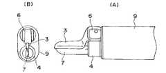
図10(A)及び図10(B)に本発明の第2実施例の主要部を示す。
本実施例は第1実施例とほぼ同様な構成であるが、主に生体組織の切開を目的としており把持部材1が設けられていない。その代わりに可動部3の遠位端と先端部材7により鋏が形成されており、生体組織の切開を効率良く、かつ安全に行える様になっている。
【0073】
その他の構成は第1実施例と同様である。この実施例では可動部3の遠位端と先端部材7の先端を切開しようとする生体組織に押し当てて可動部3を開いた状態から閉じる方向に可動させることにより、挟部分に接触する生体組織に超音波振動を印加して生体組織を切除できる。
【0074】
つまり、第1実施例の把持して切開及び凝固(の少なくとも一方を)する機能の代わりに、挟みで挟んで切除(或いは切開)する機能である。また、図10では示していないノブ12を操作して処置部33をプローブ8の中心軸(つまり超音波振動子50の中心軸)の回りで回転することができることは第1実施例と同様である。
また、第1実施例と同様に分解及び組立ができるので、分解して洗浄及び滅菌等を行う等が可能である。この実施例の効果は第1実施例とほぼ同じである。
【0075】
(第3実施例)
図11(A)及び図11(B)は本発明の第3実施例の主要部を示す。
本実施例は第1実施例とほぼ同様な構成であるが、可動部3の把持部材1と先端カバー6に挟まれた部分の先端部材7と対向する面に切開面62が形成されている。
【0076】
その為に把持部材1と先端部材7で生体組織を把持し、凝固面61を用いて生体組織を凝固すると共に、凝固面61の近位側の幅を細くして切開面62を形成し、この切開面62と先端部材7とで把持する細い幅の生体組織の切開を行える様にしている。その他は第1実施例と同様の構成である。
【0077】
この構成れにより例えば凝固しながら切開を行う場合では、生体組織の端部から順番に把持して超音波振動を加える事により、切開する部分は必ず事前に凝固される様になるので、出血する可能性を低くでき、非常に安全な切開を行う事が出来る。
その他の作用及び効果は第1実施例と同様である。
【0078】
(第4実施例)
図12は本発明の第4実施例における主要部を示す。
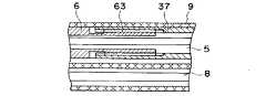
本実施例は第1実施例とほぼ同様な構成であるが、鉗子ユニット58とシース9の固定方法がスナップフィット38では無く、図2のF−F′断面付近と同等な部分の断面を示している図12に示す様に、先端カバー6と噛合部材37により形成されている噛合ネジ部63により分解及び組立可能な構造にしている。
【0079】
その他は第1実施例と同様な構成である。この実施例の作用は分解の際に固定を解除する操作と組立の操作が一部異なるのみで、その作用及び効果は第1実施例と殆ど同じである。
【0080】
(第5実施例)
図13は本発明の第5実施例における主要部を示す。
本実施例は第1実施例とほぼ同様な構成であるが、鉗子ユニット58とシース9の固定方法がスナップフィット38ではなく、図13に示している様に先端カバー6に設けられたカムロック64と噛合部材37の突起部39(図2、図5(E)参照)により分解及び組立可能な構造となっている。
【0081】
その他は第1実施例と同様な構成である。この実施例の作用は分解の際に固定を解除する操作と組立の操作が一部異なるのみで、その作用及び効果は第1実施例と殆ど同じである。
【0082】
(第6実施例)
図14は本発明の第6実施例における主要部を示す。
本実施例は第1実施例とほぼ同様な構成であるが、鉗子ユニット58とシース9の固定方法がスナップフィット38では無く、図2のE−E′断面付近と同等な部分の断面を示している図14に示す様に、接合ネジ65により分解及び組立可能な構造となっている。つまりシース、噛合部材37を貫通して先端カバー6にはネジ孔が形成され、このネジ孔には接合ネジ65が螺着されるようになっており、この接合ネジ65により分解及び組立可能な構造にしている。なお、必要に応じて、水密を保持するOリングを介在させて接合ネジ65で螺着するようにしても良い。
【0083】
その他は第1実施例と同様な構成である。この実施例の作用は分解の際に固定を解除する操作と組立の操作が一部異なるのみで、その作用及び効果は第1実施例と殆ど同じである。
【0084】
(第7実施例)
図15(A)及び図15(B)は本発明の第7実施例における回動係止の為の固定機構を示し、図15(A)はパイプ14と第1の軸受け15或いは第2の軸受け19との固定機構を示し、図15(B)はボールクリックを用いた回動係止の固定機構部分を示す。
【0085】
本実施例は第1実施例とほぼ同様な構成であるが、軸受け15或いは軸受け19とパイプ14においてボールクリックを用いた回動係止の固定機構が設けられている。
パイプ14には内外を貫通する孔にバネ等の弾性部材79を収納し、この弾性部材79の外側に収納したボール78を弾性部材79の弾性力で外周方向に付勢している。ここでパイプ14に設けられているボール78が通る孔の外側端部での直径はボール78直径よりも小さい内径となるように設定しているので付勢されたボール78が孔から突出して脱落する危険性は無い。
【0086】
このボール78と軸受け15或いは軸受け19の内周面に中心軸と平行な方向に沿って多数設けられているクリック溝80により任意の角度で操作手段34に対して処置部33を小さな角度を単位としてその角度の整数倍の任意の角度位置に回動して固定(ロック)する事が出来る様になっている。
【0087】
つまり、通常の使用状態では突出するボール78がクリック溝80に係入されてた係合状態にして回転(回動)が規制された固定状態に設定でき、この係合を解除するような回転力で回動することにより固定位置を可変設定できるようにしている。
【0088】
その他は第1実施例と同様な構成である。この実施例の作用は分解の際にこの固定機構を解除する操作と組立の操作が一部異なるのみで、その作用及び効果は第1実施例と殆ど同じである。
【0089】
(第8実施例)
図16及び17は本発明の第8実施例に係り、図16は操作手段34における主要部を示し、図17は図16の後方側から見た第2の軸受け19とシース22との回動係止のための固定機構を示す。
【0090】
本実施例は第1実施例とほぼ同様な構成であるが、第2の軸受け19におけるシース22に対向するリング形状の端面(図16から分かるように近位側端面)には放射状に多数のクリック溝80が形成されており、一方シース22におけるこの端面に対向する端面にはクリック爪81が例えば2箇所に設けてあり、クリック溝80とクリック爪81との係合により回動係止の為の固定機構が形成されている。又、ノブ12は弾性部材で成形されている。その他は第1実施例と同様の構成である。
【0091】
これらの構成により、処置部33の回動操作を行う場合にはノブ12を近位側に操作手段34に押しつける様にする。それによりノブ12が軸受け15と接触して弾性変形し、クリック爪81がクリック溝80から外れる。
【0092】
そこでノブ12を操作手段34に対して回動させる事により、処置部33が操作手段34に対して回動する。ここでノブ12を操作手段34に押しつける力量を解除するとクリック爪81がクリック溝80に再び噛合して回動が規制される係止状態に設定できる。
【0093】
又、クリック爪81がクリック溝80に噛合したまま、ノブ12を強制的に操作手段34に対して回動させてもクリック爪81がクリック溝80の山を乗り越える際にノブ12が前述の様に弾性変形するので、処置部33を操作手段34に対して回動させる事が出来る。その他の効果は第1実施例と同様である。
【0094】
(第9実施例)
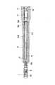
図18〜23は本発明の第9実施例に係り、図18は第9実施例の全体を示し、図19は処置部及びプローブを示し、図20(A)〜(D)は図19の各部の断面を示し、図21は挿入部を示し、図22は操作手段を示し、図23(A)〜(C)は図22の各部の断面を示す。
【0095】
第1実施例の超音波切開凝固装置31では保護部材としての機能を有するシース9内に2つの中空管路を形成し、その一方に処置部33を設けた鉗子ユニット58を通し、他方の管路に超音波振動子50からの超音波を伝達するプローブ8側を通し、鉗子ユニット58の近位端側を操作手段34の可動操作手段に係止し、この可動操作手段を操作することによりプローブ8の先端部材7に対して開閉できる構造にしたが、この実施例では保護部材としての機能を有するシース9は円筒状の中空管路(単一の管路)であり、このシース9内に略筒状のプローブ8を通し、このプローブ8内に処置部33の可動部材に連結した伝達部材側を挿通し、この伝達部材の近位端を、リング状の超音波振動子50の中空部内を後方側に延出させて可動操作手段に連結した構造にしている。
【0096】
超音波切開凝固装置31は図18に示す様に処置部33と、この処置部33を生体内に挿入する為の挿入部57を有し、この挿入部57の近位端には処置部33を操作する操作手段34が設けられている。この操作手段34の上部近位側には処置部33に処置の為の超音波振動を供給する超音波振動子50を内蔵したハンドピース32が設けられている。
【0097】
処置部33及び処置部33に超音波振動子50からの超音波振動を伝達するプローブ8等の構成は図19〜21の様になっている。処置部33はプローブ8遠位端に螺合され、超音波振動により生体組織に処置を行う先端部材7が設けられている。
【0098】
先端部材7の遠位端は鉗子状に成形されており、中央部から近位端には可動部3を挟み込む先端カバー6が形成されている。可動部3と先端部材7の遠位端は互いに噛み合い、組織を把持したり開放する鉗子としての機能を有する様になっている。
【0099】
本実施例では通常、剥離鉗子と呼ばれる遠位端が細く剥離操作に有効な形状になっているが、この形状は例えば第2実施例の様に鋏形状にしたり、第3実施例の可動部3の様な形状としても良く、その形状に制限は特にない。
【0100】
又、可動部3はピン35により先端カバー6に回動自在に支持されており、ピン36により伝達部材5と連結されている。又、伝達部材10は伝達部材5の近位端に螺合されている。
【0101】
先端カバー6の近位側とプローブ8は中空に形成されており、第1の伝達部材5、第2の伝達部材10がその内部を貫通している。第2の伝達部材10の外周面にはPTFE材等の耐熱性と超音波振動吸収性のある材料で形成されているチューブ66で被覆しており、超音波振動がプローブ8に加えられた場合に、プローブ8と伝達部材10が接触する事で金属音が発生したり接触部が発熱する、あるいは破損する等の危険を防止している。
【0102】
第1実施例と同様に伝達部材10の近位端には係合部材42が螺合により連結されており、この係合部材42の近位端には球状部43が形成されている。この係合部材42が可動操作ハンドル30の開閉操作により進退駆動され、伝達部材5が進退駆動される事によりピン36を通じて可動部3に力量が伝達され、可動部3が先端部材7に対して開閉駆動される。
【0103】
又、係合部材42の外周面には後述する高周波電流を用いた処置の際に術者の手等に高周波電流が漏れる危険を防止する為に、PTFE材等の電気絶縁性を有する材料で形成されたチューブ67で被覆している。
プローブ8は例えば3つの部品から形成されており、図19(A)のQ,Rに示されている部分でTig溶接等により連結して組立てられている。
【0104】
図20(A)に示すように可動部3を回転自在に支持するピン35は先端カバー6にカシメあるいはレーザ溶接等で固定されているので、先端カバー6と一体となっており、前述の様に先端カバー6に超音波振動が伝達されると、ピン35を経由して可動部3にも超音波振動が伝達される様になっている。
【0105】
以上の様な構造となっている処置部33とプローブ8が後述する挿入部57内に挿入され、操作手段34のハンドピース32の超音波振動子50に連結される。
【0106】
挿入部57は図21に示す様な構成をしており、複数の部品により構成されるシース9の遠位端にシース9と前述の先端カバー6や先端部材7が接触する事により、金属音が発生したり発熱する、あるいは両者が破損する等の危険を防止する為にPTFE材やセラミック等の耐熱性と超音波振動に耐性のある材料で形成されている保護部材4が設けられている。
【0107】
シース9の近位端外周にはOリング68とCリング69が設けられており、後述するネジリング82に水密で接続される。本実施例ではシース9とネジリング82の接続がCリング69による脱着となっているが、例えば第1実施例のスナップフィット38と突起部39による構造や、第4実施例の様な接合ネジ部63による接続機構あるいは、第5実施例の様なカムロック64によるもの、第8実施例の様な接合ネジ65による方法でも良く、特に接続方法に制限はない。
【0108】
次に操作手段34について述べる。図22に示すように操作手段34は支持部材72上部の遠位側に第1の軸受け15がネジ71により接合されており、中央上部付近で第2の軸受け19がネジ73により接合されている。
【0109】
第1の軸受け15の遠位側にはネジリング82が挿入されており、この軸受け15を挟んでハンドピース32と螺合されている。そしてネジリング82はハンドピース32と共に、第1の軸受け15に回動自在になっており、Oリング45により水密が保たれている。
【0110】
又、ネジリング82の遠位側には前述のシース9がCリング69により接合されており、第1の軸受け15とは回動自在にOリング68等の水密手段により水密状態が保たれている。この実施例では、第1の軸受け15の上部には送水/吸引口金51が設けられており、この送水/吸引口金51に図示しない送水/吸引手段を接続する事により、第1の軸受け15からシース9を経由する管路を用いて送水或いは吸引を行う事が出来る。
【0111】
ハンドピース32の近位側は第2の軸受け19内に挿通されており、Oリング47により支持されている。ハンドピース32は前述のOリング45とOリング47により、回動が必要な場合には回動させる事が可能であり、不用意に回動しない適度な回動抵抗を持って操作手段34に対して回動自在となっている。
【0112】
この回動係止の固定機構はOリング47以外に例えば第7実施例の様なボールクリック機構や第8実施例の様なクリック機構を用いたものでもよい。
【0113】
ハンドピース32内部には前述の様に生体組織に処置を行う為の超音波振動を供給する超音波振動子50がリング状に設けられており、この超音波振動子50で発生した超音波振動の駆動軸(振動軸)の遠位端には前述のプローブ8の近位端が螺着により連結されている。
【0114】
このプローブ8内部には前述の第2の伝達部材10が挿通されており、超音波振動子50内部の管路を通じてハンドピース32の近位端の後方側に突出している。
この際、ハンドピース32の近位端側に延びるこの伝達部材10が挿通されている管路を通じて気腹ガス等が漏洩する事を防止する目的で、この管路と第2の伝達部材10の近位端付近には略チューブ状の気密部材74が設けられており、この気密部材74は例えばゴム等の弾性部材やPTFE材等のシール部材で成形されている。
【0115】
第2の伝達部材10の近位端には係合部材42が螺着で連結されており、この係合部材42の外周には後述する高周波電流による処置の際に、高周波電流が漏電する事を防止する為にPTFE材等の電気絶縁性のある材質で形成されたチューブ67で被覆されている。
【0116】
この係合部材42の近位端には球状部43が設けられており、図23(A)に示す様に可動操作ハンドル30上部に挿入されている係合受け部材75に噛合している。この係合受け部材75は図23(A),図23(B)に示す様に上下方向に溝状となっており、この溝内を球状部43が摺動する事が出来る様になっている。
【0117】
ここで係合受け部材75の溝開口部は上部が球状部43が通過出来る幅で開口しており、下部は球状部43が通過出来ない幅で開口している。そしてこの下部の開口部には球状部43の根本の部分が挟まる様になっており、通常はこの下部の溝内に球状部43が係合している。
【0118】
この構造により可動操作ハンドル30を固定操作ハンドル29に対して開閉する事で、係合部材42を進退駆動する事が出来、係合部材42が進退駆動する事によりこれに螺着されている伝達部材10、伝達部材5が進退駆動され、それにより可動部3が先端部材7に対して開閉駆動される。
【0119】
支持部材72の近位端には固定操作ハンドル29がネジ76とナット77により結合されており、固定操作ハンドル29には図23(B)に示す様に可動操作ハンドル30が回動自在に支持されているので、前述の様に固定操作ハンドル29に対して可動操作ハンドル30を開閉操作する事が出来る。
【0120】
次に本実施例の実際の使用例について述べる。
まず、処置を行う生体組織に処置部33を対向させる。次にハンドピース32を操作手段34に対して回動させ、生体組織を処置するのに都合の良い向きに処置部33を合わせる。
【0121】
そして可動操作ハンドル30を開放方向に回動させ、可動部3を開放させる。処置を行う生体組織を適当な力量を把持する。その後、図示しない超音波振動子50の駆動電源により超音波振動子50を駆動し、先端部材7と可動部3に超音波振動を伝達し生体組織に超音波振動を与える。
【0122】
この時に前述の様に超音波振動の振幅を大きくする、把持力量を大きくする、超音波振動を与える時間を長くするといったファクタで処置を行うと、生体組織を切開するのに都合が良く、逆のファクタにすると凝固を行うので都合が良いので、生体組織の状況等を考慮して適切な処置を行う。
【0123】
又、図示しない高周波電流供給電源を超音波振動子50に印加する事により、超音波振動子50からプローブ8、先端カバー6、先端部材7、可動部3を通じて生体組織に高周波電流を与える事が出来、高周波電流を用いた処置を行う事も出来る。
【0124】
この際に前述の様に外部に露出している係合部材42外周が電気絶縁性のあるチューブ67によって被覆されており、可動操作ハンドル30、シース9、ネジリング82、軸受け15、ハンドピース32、ケーシング等をPEEKやポリサルフォン等の電気絶縁性のある材料で成形する事により、高周波電流の漏電を防止出来るので安全に処置が行える。
【0125】
超音波振動による処置と高周波電流による処置は独立して行う事が出来るので、それぞれを別々に用いて処置を行っても良く、あるいは同時に用いて処置を行っても良い。
【0126】
次に本実施例の分解及び組立方法について述べる。
まず、シース9をネジリング82から遠位方向に引き抜く。次に固定操作ハンドル29をネジ76を取り外す事により、支持部材72から下方に取り外す。これに伴い、可動操作ハンドル30も下方に移動するので、前述の係合受け部材75に係合している球状部43が溝から外れる事により、係合部材42が可動操作ハンドル30から脱落する。
これにより、固定操作ハンドル29、可動操作ハンドル30が一体となったものが操作手段34より分解される。
【0127】
続いてネジリング82をハンドピース32から取り外し、それにより軸受け15からも分解される。その後、ハンドピース32を近位側に軸受け15、軸受け19から引き抜く事により、ハンドピース32とプローブ8等が一体となったものが操作手段34から分解される。
【0128】
ハンドピース32からプローブ8を取り外し、伝達部材10から係合部材42を取り外す。その後、プローブ8から先端部材7を取り外す。
以上の分解操作により超音波切開凝固装置31は洗浄及び滅菌が良好に行える状態になり、各部の洗浄及び滅菌を行う事が出来る。
【0129】
再度、超音波切開凝固装置31を組立てる場合には前記分解手順の逆の手順で組み立てる事が出来る。
又、この様に分解及び組立が出来るので、万一、一部が破損した場合等にはその部品のみを交換する事で再び使用出来る様になっている。
【0130】
(第10実施例)
図24は本発明の第10実施例を示す。
【0131】
本実施例の構成は第9実施例とほぼ同様であるが、プローブ8が湾曲しており、シース9とその内部を挿通されている伝達部材10とが弾性部材で形成されている。伝達部材10は例えばNi−Ti合金等で製造されている超弾性ワイヤ等で形成されている。シース9は例えばPTFE材等の可撓性部材で成形されている。
【0132】
これにより、湾曲しているプローブ8をシース9内部に挿入する事が出来ると共に、プローブ8内を伝達部材10が進退駆動可能となっている。
【0133】
これらの構成により、処置部33が操作手段34に対して回動出来る事とあいなって良好な操作性で得られている。
その他の構成、動作等は第9実施例と同様である。
【0134】
なお、上述の各実施例等において、例えばネジとネジ孔或いは雄ネジと雌ネジとの螺合或いは螺着による分解及び組立可能な構造においてはネジ或いは雄ねじを設けた部材とネジ孔或いは雌ネジを設けた部材とを入れ換える等しても良いことは明らかであるし、突起或いは爪或いはピン等と凹部或いは溝等との噛合或いは係合等の場合も同様である。
【0135】
以上の様に本発明の主旨である、超音波切開凝固装置の生体組織に対して処置を行う処置部を生体内に挿入する為の挿入部のシースを操作手段に対して回動自在にしたという点に沿った範囲であれば、その他の構成はどの趣旨のものでも良くその内容に制限は無い。
【0136】
【発明の効果】
以上述べたように本発明によれば、手間をかけないで確実に洗浄及び滅菌ができ、一部の交換等を容易に行うことのできる超音波切開凝固装置を提供することができる。
【図面の簡単な説明】
【図1】本発明の第1実施例の全体図。
【図2】処置部と挿入部の構造を示す断面図。
【図3】図2のD1−D2−D3−D4線断面図。
【図4】図2の正面から見た処置部の正面図。
【図5】図2のA−A′〜G−G′線断面図。
【図6】操作手段を示す平面図。
【図7】操作手段及びその一部を拡大して示す部分断面図。
【図8】図7(A)のH−H′線及びI−I′線断面図。
【図9】図7(A)のJ−J′〜M−M′線断面図。
【図10】本発明の第2実施例における処置部の正面及び側面形状を示す図。
【図11】本発明の第3実施例における処置部の形状及び可動部の一部を示す図。
【図12】本発明の第4実施例における挿入部の一部を示す断面図。
【図13】本発明の第5実施例における処置部を示す斜視図。
【図14】本発明の第6実施例における挿入部の一部を示す断面図。
【図15】本発明の第7実施例における操作手段の軸受け部及びボールクリック機構を示す図。
【図16】本発明の第8実施例における操作手段を示す断面図。
【図17】第8実施例における操作手段の軸受け部を示す斜視図。
【図18】本発明の第9実施例の全体図。
【図19】処置部及びプローブと処置部の一部の断面を示す図。
【図20】図19のN−N′〜P−P′線及びS−S′線断面図。
【図21】挿入部を示す断面図。
【図22】操作手段を示す断面図。
【図23】図22のT−T′〜V−V′線断面図。
【図24】本発明の第10実施例の全体図。
【符号の説明】
1…把持部材
2…ネジ
3…可動部
4…保護部材
5、10…伝達部材
6…先端カバー
7…先端部材
8…プローブ
9、11、22…シース
12…ノブ
13、20…結合部材
14、18…パイプ
15、19…軸受け
16、17…駆動部材
21…ガイドシース
23、24…リング
25…駆動ピン
26…駆動部材
27、28…ネジ
29…固定操作ハンドル
30…可動操作ハンドル
31…超音波切開凝固装置
32…ハンドピース
33…処置部
34…操作手段
38…スナップフィット
39…突起部
40…回転防止機構
41…連結部材
42…係合部材
43…球状部
45、47、48…Oリング
50…超音波振動子
56…係合溝
57…挿入部[0001]
[Industrial application fields]
The present invention relates to an ultrasonic incision and coagulation apparatus that performs treatment such as incision or coagulation using ultrasonic waves.
[0002]
[Prior art]
Conventionally, it is generally known to perform treatment on a living tissue using ultrasonic vibration, and among them, those that perform treatment while being fixed to an ultrasonic treatment instrument such as adsorbing or grasping the living tissue. there were.
[0003]
For example, in Japanese Patent Application No. 62-127042, a calculus is grasped and crushed by ultrasonic vibration. In Japanese Patent Application No. 1-223294, a biological tissue is grasped and fixed by grasping forceps, and a probe that vibrates ultrasonically. An incision was made. In Japanese Patent Application No. 1-223245, a living tissue is adsorbed and fixed, and an incision is made with an ultrasonically vibrating knife.
[0004]
Further, in Japanese Patent Application No. 1-232948, the biological tissue can be efficiently excised by applying ultrasonic vibration to the excision forceps. The biological tissue is fixed by means, and treatment is applied to the biological tissue by a treatment member to which ultrasonic vibration is applied. In USP 5,322,055, a gripping member is provided on the top of the probe. The tissue was fixed for treatment. Since these can be treated by grasping a living tissue like ordinary surgical forceps, it is generally easier to perform a better treatment than when a probe alone is used.
[0005]
Also, some of the so-called ultrasonic suction devices such as USP 4,988,334 and Japanese Patent Application No. 2-203573 have a sheath that can be disassembled and assembled to the handpiece. There is no such thing that has a gripping member as mentioned above, and there is nothing especially that can be disassembled and assembled, so it is necessary to wash and sterilize each part with great care during the washing and sterilization process. There was a lot of trouble. Alternatively, it may be disposable to save this effort, but there are problems in terms of reducing the amount of medical treatment, reducing contaminated waste, and saving resources.
[0006]
Also, if any part is damaged, it is necessary to repair or replace the whole. Furthermore, several types of each part are prepared and cannot be used in an optimal combination for treatment, and it is necessary to prepare only the necessary types of ultrasonic treatment tools.
[0007]
For those equipped with means that can grasp biological tissue with an ultrasonic treatment device, there are problems in handling personnel, time, and costs, and this burden is one of the causes of the increase in medical costs. There was a possibility.
[0008]
Conventionally, in a treatment instrument used in endoscopic surgery, a treatment portion that generally performs treatment on a living tissue is a distal portion of a sheath, which is an insertion portion for inserting the treatment portion into the living body. An operating means for operating the treatment portion was provided at the proximal end of the insertion portion.
[0009]
Among these treatment tools for endoscopic surgery, there are known devices that can be disassembled and assembled into an insertion portion, a treatment portion, an operation portion, etc., as in DE7330291 and Japanese Patent Application No. 6-179049. And this structure enables more reliable cleaning and sterilization of each part in the cleaning and sterilization process. For example, when only the treatment part is damaged, only that part can be replaced, or several kinds of each part are prepared. By doing so, the above-mentioned problems have been solved to some extent because there is a merit such that various treatment parts can be combined to prepare an optimal treatment tool for treatment.
[0010]
However, in general, such a treatment tool can use only a high-frequency current when incising and coagulating a living tissue. However, the high-frequency current has a wide range of protein denaturation in living tissues, which may cause excessive treatment in some cases. If possible, it should be used in combination with ultrasonic vibration depending on the situation. Such a treatment tool alone was impossible.
[0011]
[Problems to be solved by the invention]
In the ultrasonic treatment tool as described above, there was no particular thing that could be disassembled and assembled, so that it was necessary to clean and sterilize each part with great care during the cleaning and sterilization process. It took time and effort. Alternatively, it may be disposable to save this effort, but there are problems in terms of reducing the amount of medical treatment, reducing contaminated waste, and saving resources.
[0012]
Also, if any part is damaged, it is necessary to repair or replace the whole. Furthermore, several types of each part are prepared and cannot be used in an optimal combination for treatment, and it is necessary to prepare only the necessary types of ultrasonic treatment tools.
For this reason, there are problems in handling personnel, time, and costs, and the burden may eventually become one of the causes of the increase in medical costs.
[0013]
The present invention has been made in view of the above points, and an object thereof is to provide an ultrasonic dissection and coagulation apparatus that can be reliably cleaned and sterilized without taking time and can easily be partially exchanged. And
[0014]
[Means for Solving the Problems]
The ultrasonic incision coagulation apparatus of the present invention comprises a sheath that constitutes an insertion part that can be inserted into a subject,
An ultrasonic transducer that generates ultrasonic vibrations for treating the subject;
A vibration transmitting member that is connected to the ultrasonic transducer so as to be able to transmit the ultrasonic vibration to the subject, and is inserted into the sheath;
A gripping member for gripping the living tissue of the subject by a rotating action between the distal end portion of the vibration transmitting member;
A long shaft-like member that can be inserted into the sheath, connected to the gripping member at a distal end, and moved forward and backward in the axial direction in the sheath according to the operation of the operating means. A transmission member for transmitting the movement of the means to the gripping member;
A cover member that can be inserted into the sheath and covers the transmission member so as to be movable forward and backward in the axial direction, and is detachably fixed to the sheath in the axial direction when inserted into the sheath. A support member comprising a fixing means and rotatably supporting the grip member by a pivot pin at a distal end portion;
A forceps unit insertion channel formed in the sheath, capable of inserting at least a proximal end side of a forceps unit formed integrally with the gripping member, the transmission member, and the support member;
Comprising
The forceps unitof Proximal endThe Of the forceps unit insertion channelFrom the distal end side The support member constituting the forceps unit is inserted and fixed to the sheath so as to be detachable in the axial direction by the fixing means.Ru .
[0015]
【Example】
(First embodiment)
1 to 9 relate to a first embodiment of the present invention, FIG. 1 is an overall view of the first embodiment of the present invention, FIG. 2 is a sectional view showing the structure of a treatment section and an insertion section, and FIG. 4 is a cross-sectional view taken along line D1-D2-D3-D4, FIG. 4 is a front view of the treatment section viewed from the front of FIG. 2, FIG. 5 is a cross-sectional view taken along lines AA 'to GG' of FIG. FIG. 7 is an enlarged partial sectional view showing the operating means and a part of the operating means, FIG. 8 is a cross-sectional view taken along lines HH ′ and II ′ in FIG. FIG. 8 is a sectional view taken along line JJ ′ to MM ′ in FIG.
[0016]
As shown in FIG. 1, the ultrasonic incision and
[0017]
A
[0018]
As shown in FIG. 2, the
The
[0019]
The
As shown in FIG. 3, a
[0020]
As shown in FIGS. 2 and 3, the
[0021]
A
[0022]
A
[0023]
The
[0024]
As will be described later, the gripping
[0025]
As shown in FIGS. 2 and 3, a substantially cylindrical engaging
[0026]
At this time, if the gripping
[0027]
That is, when the
[0028]
At this time, the portion where the
The proximal end of the
[0029]
A
[0030]
Further, the distal end vertex of the
[0031]
As shown in FIG. 2, a
[0032]
The operation means 34 is shown in FIGS. The operating means 34 is provided at the proximal end of the
[0033]
When the
[0034]
The
[0035]
Therefore, when the
[0036]
7 and the like, the center axis of the
[0037]
As shown in FIGS. 8A and 8B, the
[0038]
Further, the
[0039]
The engaging
[0040]
The
[0041]
A
[0042]
Further, by rotating the
[0043]
The
[0044]
Further, in order to shut off the pipe line through which the
[0045]
As will be described later, when treatment is performed by supplying a high-frequency current to the
[0046]
With this structure, the
[0047]
In such a case, the exposed surfaces of the
[0048]
Further, since the conduit through which the
[0049]
Further, a connecting portion of a
[0050]
As described above, the engaging
[0051]
Engaging
In addition, the movable operation handle 30 and the fixed operation handle 29 hold the movable operation handle 30 rotatably by
[0052]
Accordingly, by performing an operation of moving the movable operation handle 30 back and forth with respect to the fixed operation handle 29, the
[0053]
That is, when the finger hook on the lower end side of the movable operation handle 30 is opened / closed, the
[0054]
Further, by rotating the
[0055]
That is, when the
[0056]
Next, an actual usage method of this embodiment will be described.
First, the ultrasonic incision and
[0057]
Then, the movable operation handle 30 is operated in the opening direction to open the gripping
[0058]
Therefore, driving power is supplied from the driving power source of the
[0059]
For example, if the time is long, the amplitude is large, and the gripping force is strong, it is convenient for incision, and the opposite factor is convenient for coagulation.
In addition, when the living tissue is simply grasped, the living tissue can be grasped by the
[0060]
Also, when performing a biological tissue peeling operation, whether the grasping
Furthermore, the incision and coagulation operation of the living tissue can be performed by pressing the
[0061]
When treatment with a high-frequency current is required, a high-frequency current is supplied to the
[0062]
As a result, a high-frequency current is applied to the living tissue from the
If necessary, treatment using ultrasonic vibration and treatment using high-frequency current may be used in combination.
[0063]
Next, the disassembly and assembly method of this embodiment will be described.
First, with respect to the ultrasonic incision and
[0064]
Next, the gripping
[0065]
Subsequently, the
[0066]
Thereafter, the
[0067]
To disassemble the
[0068]
The ultrasonic incision and
[0069]
Further, the fixed operation handle 29 and the movable operation handle 30 can be disassembled by disassembling the
[0070]
When each member disassembled in this way is cleaned and sterilized, and after cleaning and sterilization is completed and reassembled, the assembly of the ultrasonic
In addition, since the structure can be disassembled and assembled in this way, it is possible to clean and sterilize each part sufficiently and without undue effort by disassembling, and in the event that some parts are damaged. Only the damaged parts can be replaced and can be used economically.
[0071]
Further, since the
[0072]
(Second embodiment)
10 (A) and 10 (B) show the main part of the second embodiment of the present invention.
The present embodiment has substantially the same configuration as the first embodiment, but is mainly intended for incision of living tissue and is not provided with the gripping
[0073]
Other configurations are the same as those of the first embodiment. In this embodiment, the distal end of the
[0074]
That is, instead of the function of grasping and incising and coagulating (at least one of them) in the first embodiment, it is a function of excision (or incision) by pinching it. Further, the
Further, since disassembly and assembly can be performed in the same manner as in the first embodiment, disassembly and cleaning, sterilization, and the like are possible. The effect of this embodiment is almost the same as that of the first embodiment.
[0075]
(Third embodiment)
FIGS. 11A and 11B show the main part of the third embodiment of the present invention.
This embodiment has substantially the same configuration as that of the first embodiment, but an
[0076]
For this purpose, the living tissue is grasped by the grasping
[0077]
For example, when making an incision while coagulating with this configuration, the incised part is always coagulated in advance by grasping in order from the end of the living tissue and applying ultrasonic vibration, so that bleeding occurs. The possibility is low and a very safe incision can be made.
Other operations and effects are the same as those of the first embodiment.
[0078]
(Fourth embodiment)
FIG. 12 shows a main part in the fourth embodiment of the present invention.
The present embodiment has substantially the same configuration as the first embodiment, but the fixing method of the
[0079]
Other configurations are the same as those of the first embodiment. The operation of this embodiment is almost the same as that of the first embodiment except that the operation for releasing the fixing at the time of disassembly and the assembly operation are partially different.
[0080]
(5th Example)
FIG. 13 shows a main part in the fifth embodiment of the present invention.
This embodiment has substantially the same configuration as that of the first embodiment, but the fixing method of the
[0081]
Other configurations are the same as those of the first embodiment. The operation of this embodiment is almost the same as that of the first embodiment except that the operation for releasing the fixing at the time of disassembly and the assembly operation are partially different.
[0082]
(Sixth embodiment)
FIG. 14 shows a main part in the sixth embodiment of the present invention.
The present embodiment has substantially the same configuration as that of the first embodiment, but the fixing method of the
[0083]
Other configurations are the same as those of the first embodiment. The operation of this embodiment is almost the same as that of the first embodiment except that the operation for releasing the fixing at the time of disassembly and the assembly operation are partially different.
[0084]
(Seventh embodiment)
15 (A) and 15 (B) show a fixing mechanism for rotational locking in the seventh embodiment of the present invention, and FIG. 15 (A) shows the
[0085]
This embodiment has substantially the same configuration as that of the first embodiment, but the
An
[0086]
A plurality of
[0087]
That is, in a normal use state, the protruding
[0088]
Other configurations are the same as those of the first embodiment. The operation of this embodiment is almost the same as that of the first embodiment except that the operation for releasing the fixing mechanism and the assembly operation are partially different during disassembly.
[0089]
(Eighth embodiment)
FIGS. 16 and 17 relate to an eighth embodiment of the present invention. FIG. 16 shows the main part of the operating means 34. FIG. 17 shows the rotation of the
[0090]
This embodiment has substantially the same configuration as that of the first embodiment, but a large number of radial ends are provided on the ring-shaped end face (proximal end face as can be seen from FIG. 16) of the
[0091]
With these configurations, the
[0092]
Therefore, when the
[0093]
Further, even if the
[0094]
(Ninth embodiment)
18 to 23 relate to a ninth embodiment of the present invention, FIG. 18 shows the whole of the ninth embodiment, FIG. 19 shows a treatment section and a probe, and FIGS. 20 (A) to (D) show FIG. 21 shows a cross section of each part, FIG. 21 shows an insertion part, FIG. 22 shows an operating means, and FIGS. 23A to 23C show cross sections of the respective parts in FIG.
[0095]
In the ultrasonic incision and
[0096]
As shown in FIG. 18, the ultrasonic incision and
[0097]
The structure of the
[0098]
The distal end of the
[0099]
In this embodiment, the distal end called the peeling forceps is usually thin and has a shape effective for the peeling operation. For example, this shape may be a hook shape as in the second embodiment, or the movable part of the third embodiment. 3 may be used, and the shape is not particularly limited.
[0100]
The
[0101]
The proximal side of the
[0102]
Similar to the first embodiment, an engaging
[0103]
In addition, the outer peripheral surface of the engaging
The
[0104]
As shown in FIG. 20 (A), the
[0105]
The
[0106]
The
[0107]
An O-
[0108]
Next, the operation means 34 will be described. As shown in FIG. 22, in the operating means 34, the
[0109]
A
[0110]
Further, the
[0111]
The proximal side of the
[0112]
For example, a ball click mechanism as in the seventh embodiment or a click mechanism as in the eighth embodiment may be used as the rotation locking fixing mechanism.
[0113]
Inside the
[0114]
The above-described
At this time, for the purpose of preventing insufflation gas or the like from leaking through the pipe line through which the
[0115]
An engaging
[0116]
A
[0117]
Here, the groove opening portion of the
[0118]
With this structure, the movable operating handle 30 can be opened and closed with respect to the fixed
[0119]
A fixed operation handle 29 is coupled to the proximal end of the
[0120]
Next, an actual use example of this embodiment will be described.
First, the
[0121]
Then, the movable operation handle 30 is rotated in the opening direction to open the
[0122]
At this time, as described above, if the treatment is performed with factors such as increasing the amplitude of the ultrasonic vibration, increasing the gripping force amount, and increasing the time for applying the ultrasonic vibration, it is convenient for incising the living tissue. This factor is convenient because coagulation is performed, so appropriate treatment is performed in consideration of the condition of the living tissue.
[0123]
Further, by applying a high-frequency current supply power source (not shown) to the
[0124]
At this time, as described above, the outer periphery of the engaging
[0125]
Since the treatment by the ultrasonic vibration and the treatment by the high frequency current can be performed independently, the treatment may be performed using each of them separately, or the treatment may be performed simultaneously.
[0126]
Next, the disassembly and assembly method of this embodiment will be described.
First, the
As a result, the fixed operation handle 29 and the movable operation handle 30 that are integrated are disassembled by the operation means 34.
[0127]
Subsequently, the
[0128]
The
By the above disassembling operation, the ultrasonic incision and
[0129]
When the ultrasonic incision and
In addition, since disassembly and assembly can be performed in this way, in the unlikely event that a part is damaged, it can be used again by replacing only that part.
[0130]
(Tenth embodiment)
FIG. 24 shows a tenth embodiment of the present invention.
[0131]
The configuration of this embodiment is substantially the same as that of the ninth embodiment, but the
[0132]
As a result, the
[0133]
With these configurations, the
Other configurations and operations are the same as those of the ninth embodiment.
[0134]
In each of the above-described embodiments, for example, in a structure that can be disassembled and assembled by screwing or screwing a screw and a screw hole or a male screw and a female screw, a member provided with a screw or a male screw and a screw hole or a female screw. It is obvious that the member provided with the groove may be replaced, and the same applies to the case where the protrusion, claw, pin, or the like is engaged with the recess, the groove, or the like.
[0135]
As described above, the sheath of the insertion portion for inserting the treatment portion for performing treatment on the biological tissue of the ultrasonic incision and coagulation apparatus, which is the gist of the present invention, is rotatable with respect to the operation means. As long as the range is in line with the above point, the other configuration may have any purpose, and the content is not limited.
[0136]
【The invention's effect】
As described above, according to the present invention, it is possible to provide an ultrasonic incision and coagulation apparatus that can be reliably cleaned and sterilized without taking time and can easily be partially exchanged.
[Brief description of the drawings]
FIG. 1 is an overall view of a first embodiment of the present invention.
FIG. 2 is a cross-sectional view showing a structure of a treatment portion and an insertion portion.
3 is a sectional view taken along line D1-D2-D3-D4 of FIG.
FIG. 4 is a front view of a treatment section viewed from the front of FIG.
5 is a cross-sectional view taken along line AA′-GG ′ in FIG. 2;
FIG. 6 is a plan view showing an operation means.
FIG. 7 is a partial cross-sectional view showing the operation means and a part thereof in an enlarged manner.
8 is a cross-sectional view taken along line HH ′ and line II ′ of FIG.
9 is a cross-sectional view taken along line JJ ′ to MM ′ in FIG.
FIG. 10 is a diagram showing the front and side shapes of a treatment section in a second embodiment of the present invention.
FIG. 11 is a diagram showing a shape of a treatment portion and a part of a movable portion in a third embodiment of the present invention.
FIG. 12 is a sectional view showing a part of an insertion portion in a fourth embodiment of the present invention.
FIG. 13 is a perspective view showing a treatment portion in a fifth embodiment of the present invention.
FIG. 14 is a sectional view showing a part of an insertion portion in a sixth embodiment of the present invention.
FIG. 15 is a view showing a bearing portion and a ball click mechanism of an operation means in a seventh embodiment of the present invention.
FIG. 16 is a sectional view showing an operating means in an eighth embodiment of the present invention.
FIG. 17 is a perspective view showing a bearing portion of operation means in an eighth embodiment.
FIG. 18 is an overall view of a ninth embodiment of the present invention.
FIG. 19 is a diagram showing a cross section of a treatment portion, a probe, and a portion of the treatment portion.
20 is a cross-sectional view taken along line NN ′ to PP ′ and SS ′ of FIG. 19;
FIG. 21 is a cross-sectional view showing an insertion portion.
FIG. 22 is a cross-sectional view showing the operating means.
23 is a cross-sectional view taken along line TT′-VV ′ of FIG. 22;
FIG. 24 is an overall view of a tenth embodiment of the present invention.
[Explanation of symbols]
1 ... Gripping member
2 ... Screw
3 ... Moving parts
4 ... Protective member
5, 10 ... transmission member
6 ... Tip cover
7 ... Tip member
8 ... Probe
9, 11, 22 ... sheath
12 ... Knob
13, 20 ... coupling member
14, 18 ... pipe
15, 19 ... Bearing
16, 17 ... Driving member
21 ... Guide sheath
23, 24 ... Ring
25 ... Drive pin
26: Driving member
27, 28 ... Screw
29 ... Fixed operation handle
30 ... Moveable operation handle
31 ... Ultrasonic incision coagulation device
32 ... Handpiece
33 ... Treatment section
34. Operating means
38 ... Snap fit
39 ... Projection
40: Anti-rotation mechanism
41. Connecting member
42 ... engaging member
43 ... spherical part
45, 47, 48 ... O-ring
50. Ultrasonic transducer
56 ... engaging groove
57 ... Insertion section
Claims (1)
Translated fromJapanese前記被検体を処置するための超音波振動を発生する超音波振動子と、
前記超音波振動を前記被検体に伝達可能に前記超音波振動子と接続し、前記シースに挿入される振動伝達部材と、
前記振動伝達部材の遠位端部との間で前記被検体の生体組織を回動作用により把持するための把持部材と、
前記シース内に挿入可能になされた長軸状部材であって、遠位端部において前記把持部材と連結し、操作手段の操作に応じて当該シース内において軸方向に進退移動することにより前記操作手段の動きを前記把持部材に伝達する伝達部材と、
前記シース内に挿入可能になされた、前記伝達部材を軸方向に進退自在に覆うカバー部材であって、前記シースに挿入された際に当該シースに対して軸方向に着脱可能に固定するための固定手段を備え、かつ、遠位端部において前記把持部材を枢支ピンにより回動自在に支持する支持部材と、
前記把持部材、前記伝達部材及び前記支持部材とを一体的に構成して成した鉗子ユニットの少なくとも近位端側を挿入可能とする、前記シース内に形成された鉗子ユニット挿入チャンネルと、
を具備し、
前記鉗子ユニットの近位端側を前記鉗子ユニット挿入チャンネルの遠位端側より挿入し、当該鉗子ユニットを構成する前記支持部材を前記固定手段により前記シースに対して軸方向に着脱可能に固定することを特徴とする超音波切開凝固装置。A sheath that constitutes an insertion portion that can be inserted into a subject;
An ultrasonic transducer that generates ultrasonic vibrations for treating the subject;
A vibration transmitting member that is connected to the ultrasonic transducer so as to be able to transmit the ultrasonic vibration to the subject, and is inserted into the sheath;
A gripping member for gripping the living tissue of the subject by a rotating action between the distal end portion of the vibration transmitting member;
A long shaft-like member that can be inserted into the sheath, connected to the gripping member at a distal end, and moved forward and backward in the axial direction in the sheath according to the operation of the operating means. A transmission member for transmitting the movement of the means to the gripping member;
A cover member that can be inserted into the sheath and covers the transmission member so as to be movable forward and backward in the axial direction, and is detachably fixed to the sheath in the axial direction when inserted into the sheath. A support member comprising a fixing means and rotatably supporting the grip member by a pivot pin at a distal end portion;
A forceps unit insertion channel formed in the sheath, capable of inserting at least a proximal end side of a forceps unit formed integrally with the gripping member, the transmission member, and the support member;
Comprising
The proximal end sideof the forceps unit is insertedfrom thedistal end side of the forceps unit insertion channel, and the support member constituting the forceps unit is detachably fixed to the sheath by the fixing means in the axial direction. ultrasonic dissection coagulation apparatus according to claim andTurkey.
Priority Applications (6)
| Application Number | Priority Date | Filing Date | Title |
|---|---|---|---|
| JP08146695AJP3989030B2 (en) | 1995-04-06 | 1995-04-06 | Ultrasonic incision coagulator |
| US09/353,652US6669690B1 (en) | 1995-04-06 | 1999-07-15 | Ultrasound treatment system |
| US09/427,021US6340352B1 (en) | 1995-04-06 | 1999-10-26 | Ultrasound treatment system |
| US10/650,759US7780659B2 (en) | 1995-04-06 | 2003-08-29 | Ultrasound treatment system |
| US12/801,887US8672935B2 (en) | 1995-04-06 | 2010-06-30 | Ultrasound treatment system |
| US12/801,886US8574228B2 (en) | 1995-04-06 | 2010-06-30 | Ultrasound treatment system |
Applications Claiming Priority (1)
| Application Number | Priority Date | Filing Date | Title |
|---|---|---|---|
| JP08146695AJP3989030B2 (en) | 1995-04-06 | 1995-04-06 | Ultrasonic incision coagulator |
Related Child Applications (2)
| Application Number | Title | Priority Date | Filing Date |
|---|---|---|---|
| JP2003366718ADivisionJP2004041780A (en) | 2003-10-27 | 2003-10-27 | Ultrasonic cutting and coagulation device |
| JP2004190485ADivisionJP3766674B2 (en) | 2004-06-28 | 2004-06-28 | Ultrasonic incision coagulator |
Publications (2)
| Publication Number | Publication Date |
|---|---|
| JPH08275950A JPH08275950A (en) | 1996-10-22 |
| JP3989030B2true JP3989030B2 (en) | 2007-10-10 |
Family
ID=13747184
Family Applications (1)
| Application Number | Title | Priority Date | Filing Date |
|---|---|---|---|
| JP08146695AExpired - Fee RelatedJP3989030B2 (en) | 1995-04-06 | 1995-04-06 | Ultrasonic incision coagulator |
Country Status (1)
| Country | Link |
|---|---|
| JP (1) | JP3989030B2 (en) |
Families Citing this family (33)
| Publication number | Priority date | Publication date | Assignee | Title |
|---|---|---|---|---|
| JP3274826B2 (en) | 1997-10-15 | 2002-04-15 | オリンパス光学工業株式会社 | Ultrasonic treatment tool |
| JP4233742B2 (en) | 1999-10-05 | 2009-03-04 | エシコン・エンド−サージェリィ・インコーポレイテッド | Connecting curved clamp arms and tissue pads used with ultrasonic surgical instruments |
| US8182501B2 (en) | 2004-02-27 | 2012-05-22 | Ethicon Endo-Surgery, Inc. | Ultrasonic surgical shears and method for sealing a blood vessel using same |
| JP4291202B2 (en)* | 2004-04-20 | 2009-07-08 | オリンパス株式会社 | Ultrasonic treatment device |
| US20060079879A1 (en) | 2004-10-08 | 2006-04-13 | Faller Craig N | Actuation mechanism for use with an ultrasonic surgical instrument |
| US20070191713A1 (en) | 2005-10-14 | 2007-08-16 | Eichmann Stephen E | Ultrasonic device for cutting and coagulating |
| US7621930B2 (en) | 2006-01-20 | 2009-11-24 | Ethicon Endo-Surgery, Inc. | Ultrasound medical instrument having a medical ultrasonic blade |
| US8142461B2 (en) | 2007-03-22 | 2012-03-27 | Ethicon Endo-Surgery, Inc. | Surgical instruments |
| US8911460B2 (en) | 2007-03-22 | 2014-12-16 | Ethicon Endo-Surgery, Inc. | Ultrasonic surgical instruments |
| US8057498B2 (en) | 2007-11-30 | 2011-11-15 | Ethicon Endo-Surgery, Inc. | Ultrasonic surgical instrument blades |
| US8523889B2 (en) | 2007-07-27 | 2013-09-03 | Ethicon Endo-Surgery, Inc. | Ultrasonic end effectors with increased active length |
| US8808319B2 (en) | 2007-07-27 | 2014-08-19 | Ethicon Endo-Surgery, Inc. | Surgical instruments |
| US8430898B2 (en) | 2007-07-31 | 2013-04-30 | Ethicon Endo-Surgery, Inc. | Ultrasonic surgical instruments |
| US9044261B2 (en) | 2007-07-31 | 2015-06-02 | Ethicon Endo-Surgery, Inc. | Temperature controlled ultrasonic surgical instruments |
| US8512365B2 (en) | 2007-07-31 | 2013-08-20 | Ethicon Endo-Surgery, Inc. | Surgical instruments |
| EP2217157A2 (en) | 2007-10-05 | 2010-08-18 | Ethicon Endo-Surgery, Inc. | Ergonomic surgical instruments |
| US10010339B2 (en) | 2007-11-30 | 2018-07-03 | Ethicon Llc | Ultrasonic surgical blades |
| US9700339B2 (en) | 2009-05-20 | 2017-07-11 | Ethicon Endo-Surgery, Inc. | Coupling arrangements and methods for attaching tools to ultrasonic surgical instruments |
| US8486096B2 (en) | 2010-02-11 | 2013-07-16 | Ethicon Endo-Surgery, Inc. | Dual purpose surgical instrument for cutting and coagulating tissue |
| US8951272B2 (en) | 2010-02-11 | 2015-02-10 | Ethicon Endo-Surgery, Inc. | Seal arrangements for ultrasonically powered surgical instruments |
| US9820768B2 (en) | 2012-06-29 | 2017-11-21 | Ethicon Llc | Ultrasonic surgical instruments with control mechanisms |
| US10226273B2 (en) | 2013-03-14 | 2019-03-12 | Ethicon Llc | Mechanical fasteners for use with surgical energy devices |
| WO2015088012A1 (en)* | 2013-12-13 | 2015-06-18 | オリンパス株式会社 | Treatment instrument and treatment system |
| GB2521229A (en) | 2013-12-16 | 2015-06-17 | Ethicon Endo Surgery Inc | Medical device |
| US11020140B2 (en) | 2015-06-17 | 2021-06-01 | Cilag Gmbh International | Ultrasonic surgical blade for use with ultrasonic surgical instruments |
| US10357303B2 (en) | 2015-06-30 | 2019-07-23 | Ethicon Llc | Translatable outer tube for sealing using shielded lap chole dissector |
| US10245064B2 (en) | 2016-07-12 | 2019-04-02 | Ethicon Llc | Ultrasonic surgical instrument with piezoelectric central lumen transducer |
| US10893883B2 (en) | 2016-07-13 | 2021-01-19 | Ethicon Llc | Ultrasonic assembly for use with ultrasonic surgical instruments |
| USD847990S1 (en) | 2016-08-16 | 2019-05-07 | Ethicon Llc | Surgical instrument |
| US10736649B2 (en) | 2016-08-25 | 2020-08-11 | Ethicon Llc | Electrical and thermal connections for ultrasonic transducer |
| US10952759B2 (en) | 2016-08-25 | 2021-03-23 | Ethicon Llc | Tissue loading of a surgical instrument |
| US10603064B2 (en) | 2016-11-28 | 2020-03-31 | Ethicon Llc | Ultrasonic transducer |
| US10820920B2 (en) | 2017-07-05 | 2020-11-03 | Ethicon Llc | Reusable ultrasonic medical devices and methods of their use |
Family Cites Families (2)
| Publication number | Priority date | Publication date | Assignee | Title |
|---|---|---|---|---|
| ES2115068T3 (en)* | 1992-06-24 | 1998-06-16 | Microsurge Inc | REUSABLE ENDOSCOPIC SURGICAL INSTRUMENT. |
| US5322055B1 (en)* | 1993-01-27 | 1997-10-14 | Ultracision Inc | Clamp coagulator/cutting system for ultrasonic surgical instruments |
- 1995
- 1995-04-06JPJP08146695Apatent/JP3989030B2/ennot_activeExpired - Fee Related
Also Published As
| Publication number | Publication date |
|---|---|
| JPH08275950A (en) | 1996-10-22 |
Similar Documents
| Publication | Publication Date | Title |
|---|---|---|
| JP3989030B2 (en) | Ultrasonic incision coagulator | |
| US11883057B2 (en) | Ultrasonic surgical instrument with transducer slip joint | |
| CN110520068B (en) | Surgical instrument with removable clamp arm assembly | |
| JP4610823B2 (en) | Ultrasonic surgical device with removable clamp arm | |
| TWI721278B (en) | Ultrasonic surgical instruments | |
| EP3733098B1 (en) | Ultrasonic surgical instrument having detachable sleeve assembly | |
| BR112017022173B1 (en) | Device for operating on fabric | |
| WO2018111563A1 (en) | Ultrasonic surgical instrument with transducer slip joint | |
| BR112018070016B1 (en) | JOINT CONTROL AND SURGICAL INSTRUMENT SET | |
| US10492885B2 (en) | Ultrasonic surgical instrument with cleaning port | |
| BR112018007903B1 (en) | INSTRUMENT WITH ULTRASONIC BLADE | |
| JP3310532B2 (en) | Ultrasonic incision coagulation device | |
| JPH08275949A (en) | Ultrasonic dissecting and coagulating device | |
| JP3766674B2 (en) | Ultrasonic incision coagulator | |
| JP4257189B2 (en) | Ultrasonic incision coagulator | |
| JP2004041780A (en) | Ultrasonic cutting and coagulation device | |
| JP3841459B2 (en) | Ultrasonic incision coagulator | |
| JP2004073891A (en) | Ultrasonic discission and coagulation device | |
| JP3826141B2 (en) | Ultrasonic incision coagulator | |
| JP2004073890A (en) | Ultrasonic incision and coagulation device | |
| US20230355266A1 (en) | Clamp force control feature for surgical end effector | |
| BR112019024341B1 (en) | COMBINED ELECTROSURGICAL AND ULTRASONIC SYSTEM HAVING A GENERATOR FILTER CIRCUIT | |
| BR112019011896B1 (en) | ULTRASONIC SURGICAL INSTRUMENT WITH INTEGRAL DYNAMOMETRIC WRENCH AND TRANSVERSE HITCH | |
| BR112019011694A2 (en) | ultrasonic surgical tool with torque wrench for integral drive shaft assembly | |
| BR112019011896A2 (en) | ultrasonic surgical instrument with integral torque wrench and transverse hitch |
Legal Events
| Date | Code | Title | Description |
|---|---|---|---|
| A02 | Decision of refusal | Free format text:JAPANESE INTERMEDIATE CODE: A02 Effective date:20040427 | |
| A521 | Written amendment | Free format text:JAPANESE INTERMEDIATE CODE: A523 Effective date:20040628 | |
| A911 | Transfer of reconsideration by examiner before appeal (zenchi) | Free format text:JAPANESE INTERMEDIATE CODE: A911 Effective date:20040817 | |
| A912 | Removal of reconsideration by examiner before appeal (zenchi) | Free format text:JAPANESE INTERMEDIATE CODE: A912 Effective date:20041008 | |
| A521 | Written amendment | Free format text:JAPANESE INTERMEDIATE CODE: A523 Effective date:20070319 | |
| A521 | Written amendment | Free format text:JAPANESE INTERMEDIATE CODE: A523 Effective date:20070501 | |
| A61 | First payment of annual fees (during grant procedure) | Free format text:JAPANESE INTERMEDIATE CODE: A61 Effective date:20070717 | |
| FPAY | Renewal fee payment (event date is renewal date of database) | Free format text:PAYMENT UNTIL: 20100727 Year of fee payment:3 | |
| FPAY | Renewal fee payment (event date is renewal date of database) | Free format text:PAYMENT UNTIL: 20100727 Year of fee payment:3 | |
| FPAY | Renewal fee payment (event date is renewal date of database) | Free format text:PAYMENT UNTIL: 20110727 Year of fee payment:4 | |
| FPAY | Renewal fee payment (event date is renewal date of database) | Free format text:PAYMENT UNTIL: 20120727 Year of fee payment:5 | |
| LAPS | Cancellation because of no payment of annual fees |