JP3988309B2 - Phosphor and method for producing the same - Google Patents
Phosphor and method for producing the sameDownload PDFInfo
- Publication number
- JP3988309B2 JP3988309B2JP08908199AJP8908199AJP3988309B2JP 3988309 B2JP3988309 B2JP 3988309B2JP 08908199 AJP08908199 AJP 08908199AJP 8908199 AJP8908199 AJP 8908199AJP 3988309 B2JP3988309 B2JP 3988309B2
- Authority
- JP
- Japan
- Prior art keywords
- phosphor
- glass component
- phosphor particles
- coated
- zinc sulfide
- Prior art date
- Legal status (The legal status is an assumption and is not a legal conclusion. Google has not performed a legal analysis and makes no representation as to the accuracy of the status listed.)
- Expired - Fee Related
Links
- OAICVXFJPJFONN-UHFFFAOYSA-NPhosphorusChemical compound[P]OAICVXFJPJFONN-UHFFFAOYSA-N0.000titleclaimsdescription137
- 238000004519manufacturing processMethods0.000titleclaimsdescription19
- 229910052984zinc sulfideInorganic materials0.000claimsdescription78
- 239000002245particleSubstances0.000claimsdescription68
- 239000011521glassSubstances0.000claimsdescription65
- 239000005083Zinc sulfideSubstances0.000claimsdescription31
- DRDVZXDWVBGGMH-UHFFFAOYSA-Nzinc;sulfideChemical compound[S-2].[Zn+2]DRDVZXDWVBGGMH-UHFFFAOYSA-N0.000claimsdescription31
- 239000013078crystalSubstances0.000claimsdescription29
- 239000002086nanomaterialSubstances0.000claimsdescription25
- 238000006243chemical reactionMethods0.000claimsdescription23
- 229910052731fluorineInorganic materials0.000claimsdescription19
- 239000007791liquid phaseSubstances0.000claimsdescription16
- 229910052693EuropiumInorganic materials0.000claimsdescription14
- 229910052771TerbiumInorganic materials0.000claimsdescription14
- XLYOFNOQVPJJNP-UHFFFAOYSA-NwaterSubstancesOXLYOFNOQVPJJNP-UHFFFAOYSA-N0.000claimsdescription13
- PUZPDOWCWNUUKD-UHFFFAOYSA-Msodium fluorideChemical compound[F-].[Na+]PUZPDOWCWNUUKD-UHFFFAOYSA-M0.000claimsdescription12
- PXGOKWXKJXAPGV-UHFFFAOYSA-NFluorineChemical compoundFFPXGOKWXKJXAPGV-UHFFFAOYSA-N0.000claimsdescription11
- OGPBJKLSAFTDLK-UHFFFAOYSA-Neuropium atomChemical compound[Eu]OGPBJKLSAFTDLK-UHFFFAOYSA-N0.000claimsdescription11
- 239000011737fluorineSubstances0.000claimsdescription11
- GZCRRIHWUXGPOV-UHFFFAOYSA-Nterbium atomChemical compound[Tb]GZCRRIHWUXGPOV-UHFFFAOYSA-N0.000claimsdescription11
- 238000000975co-precipitationMethods0.000claimsdescription10
- 230000001678irradiating effectEffects0.000claimsdescription9
- LFQSCWFLJHTTHZ-UHFFFAOYSA-NEthanolChemical compoundCCOLFQSCWFLJHTTHZ-UHFFFAOYSA-N0.000claimsdescription8
- VEXZGXHMUGYJMC-UHFFFAOYSA-NHydrochloric acidChemical compoundClVEXZGXHMUGYJMC-UHFFFAOYSA-N0.000claimsdescription8
- ZOIORXHNWRGPMV-UHFFFAOYSA-Nacetic acid;zincChemical compound[Zn].CC(O)=O.CC(O)=OZOIORXHNWRGPMV-UHFFFAOYSA-N0.000claimsdescription8
- 238000000034methodMethods0.000claimsdescription8
- 229910052979sodium sulfideInorganic materials0.000claimsdescription8
- GRVFOGOEDUUMBP-UHFFFAOYSA-Nsodium sulfide (anhydrous)Chemical compound[Na+].[Na+].[S-2]GRVFOGOEDUUMBP-UHFFFAOYSA-N0.000claimsdescription8
- 239000004246zinc acetateSubstances0.000claimsdescription8
- GAGGCOKRLXYWIV-UHFFFAOYSA-Neuropium(3+);trinitrateChemical compound[Eu+3].[O-][N+]([O-])=O.[O-][N+]([O-])=O.[O-][N+]([O-])=OGAGGCOKRLXYWIV-UHFFFAOYSA-N0.000claimsdescription6
- 239000011775sodium fluorideSubstances0.000claimsdescription6
- 235000013024sodium fluorideNutrition0.000claimsdescription6
- YJVUGDIORBKPLC-UHFFFAOYSA-Nterbium(3+);trinitrateChemical compound[Tb+3].[O-][N+]([O-])=O.[O-][N+]([O-])=O.[O-][N+]([O-])=OYJVUGDIORBKPLC-UHFFFAOYSA-N0.000claimsdescription6
- 239000002904solventSubstances0.000claimsdescription5
- BOTDANWDWHJENH-UHFFFAOYSA-NTetraethyl orthosilicateChemical compoundCCO[Si](OCC)(OCC)OCCBOTDANWDWHJENH-UHFFFAOYSA-N0.000claimsdescription4
- 230000000379polymerizing effectEffects0.000claimsdescription2
- OKKJLVBELUTLKV-UHFFFAOYSA-NMethanolChemical compoundOCOKKJLVBELUTLKV-UHFFFAOYSA-N0.000description36
- 239000012190activatorSubstances0.000description27
- 238000010894electron beam technologyMethods0.000description20
- 239000002159nanocrystalSubstances0.000description16
- 239000000243solutionSubstances0.000description16
- 239000000126substanceSubstances0.000description15
- 238000000295emission spectrumMethods0.000description12
- 230000005284excitationEffects0.000description11
- 239000002994raw materialSubstances0.000description9
- 239000007864aqueous solutionSubstances0.000description8
- 238000005342ion exchangeMethods0.000description8
- 239000011259mixed solutionSubstances0.000description8
- 239000004065semiconductorSubstances0.000description7
- 239000011701zincSubstances0.000description6
- 238000006116polymerization reactionMethods0.000description5
- 238000010586diagramMethods0.000description4
- 239000002244precipitateSubstances0.000description4
- 238000009125cardiac resynchronization therapyMethods0.000description3
- 239000000463materialSubstances0.000description3
- 150000003839saltsChemical class0.000description3
- 230000005476size effectEffects0.000description3
- 229910052725zincInorganic materials0.000description3
- 239000011248coating agentSubstances0.000description2
- 238000000576coating methodMethods0.000description2
- 230000000694effectsEffects0.000description2
- 230000031700light absorptionEffects0.000description2
- 239000007787solidSubstances0.000description2
- 238000003756stirringMethods0.000description2
- QTBSBXVTEAMEQO-UHFFFAOYSA-MAcetateChemical compoundCC([O-])=OQTBSBXVTEAMEQO-UHFFFAOYSA-M0.000description1
- 229910002651NO3Inorganic materials0.000description1
- NHNBFGGVMKEFGY-UHFFFAOYSA-NNitrateChemical compound[O-][N+]([O-])=ONHNBFGGVMKEFGY-UHFFFAOYSA-N0.000description1
- HCHKCACWOHOZIP-UHFFFAOYSA-NZincChemical compound[Zn]HCHKCACWOHOZIP-UHFFFAOYSA-N0.000description1
- 230000005540biological transmissionEffects0.000description1
- 238000005401electroluminescenceMethods0.000description1
- 230000001747exhibiting effectEffects0.000description1
- 229910052732germaniumInorganic materials0.000description1
- PIJPYDMVFNTHIP-UHFFFAOYSA-Llead sulfateChemical compound[PbH4+2].[O-]S([O-])(=O)=OPIJPYDMVFNTHIP-UHFFFAOYSA-L0.000description1
- 230000003287optical effectEffects0.000description1
- 229910021426porous siliconInorganic materials0.000description1
- 230000002250progressing effectEffects0.000description1
- 229910052710siliconInorganic materials0.000description1
- 230000002194synthesizing effectEffects0.000description1
- 239000011882ultra-fine particleSubstances0.000description1
Images


Landscapes
- Electroluminescent Light Sources (AREA)
- Luminescent Compositions (AREA)
Description
Translated fromJapanese【0001】
【発明の属する技術分野】
本発明は、蛍光体粒子及びその製造方法に関する。
【0002】
【従来の技術】
近年、SiやGe等に代表される超微粒子、ポーラスシリコン等のII−VI族半導体においてそのナノ構造結晶が特異的な光学的特性を示すことが注目されている。ここで、ナノ構造結晶とは、数nm程度の粒径の結晶粒のことをいい、一般的にナノクリスタルと呼ばれる。
【0003】
II−VI族半導体において、上述したようなナノ構造結晶を有する場合と、バルク状の結晶を有する場合とを比較すると、ナノ構造結晶を有する場合には、良好な光吸収特性及び発光特性を示すことになる。これは、ナノ構造結晶を有するII−VI族半導体では、量子サイズ効果が発現するため、バルク状の結晶構造の場合よりも大きなバンドギャップを有するためと考えられる。すなわち、ナノ構造結晶を有するII−VI族半導体においては、量子サイズ効果によりバンドギャップが広げられるのではないかと考えられている。
【0004】
ところで、テレビ等のディスプレイには、様々な蛍光体が用いられている。現在、テレビ等のディスプレイに用いられている蛍光体の粒径は、数ミクロン(3〜10μm)程度である。そして、近年、様々なディスプレイが開発され、特に薄型化という観点でプラズマディスプレイ(PDP)やフィールド・エミッション・ディスプレイ(FED)やエレクトロ・ルミネッセンス・ディスプレイ(ELD)が注目されている。
【0005】
その中でも特に注目されているFEDでは、薄型化されると電子ビームの電圧を低下させる必要がある。しかしながら、薄型化されたディスプレイにおいて、上述したような粒径が数μm程度の蛍光体を用いると、電子ビームの電圧が低いために十分に発光しない。すなわち、このような薄型化されたディスプレイでは、従来の蛍光体を十分に励起させることができなかった。これは、従来の蛍光体の結晶が大きいため、照射された電子ビームが発光体の発光する部分にまで到達することができないためである。つまり、粒径が数μm程度の従来の蛍光体は、薄型化されたディスプレイに用いられた場合、十分に発光することがなかった。従って、蛍光体としては、低電圧で励起可能なものが、薄型化されたディスプレイ、特にFEDに適したものと言える。このような条件を満たす蛍光体として上述したようなナノ構造結晶を有するII−VI族半導体を挙げることができる。
【0006】
また、CRTの分野においてもますます高精細化が進んでおり、より微細な蛍光体が要求されており、このような条件を満たす蛍光体として、上述したようなナノ構造結晶を有するII−VI族半導体を挙げることができる。
【0007】
【発明が解決しようとする課題】
しかしながら、低電圧で励起可能な蛍光体として実用化されているものは、青緑色発光をするZnO:Znぐらいしかないのが現状である。ナノ構造結晶を有するII−VI族半導体の製造方法は、十分に検討されておらず、所望の蛍光体を製造することができない。このため、薄型化されたディスプレイ用の好適な蛍光体を製造する方法が待ち望まれている。また、超高精細CRT用の微細蛍光体を製造する方法も待ち望まれている。
【0008】
本発明は、このような従来の実情に鑑みて提案されたものであり、低電圧で励起可能であり、薄型化されたディスプレイ用に好適な蛍光体及びその製造方法を提供することを目的とする。
【0009】
【課題を解決するための手段】
本発明の蛍光体は、共沈を利用した液相反応にて合成されたナノ構造結晶を有する蛍光体粒子の周囲がガラス成分でコーティングされていることを特徴とする。
また、本発明の蛍光体は、テルビウムによって付活された硫化亜鉛からなるナノ構造結晶を有する蛍光体粒子の周囲がガラス成分でコーティングされていることを特徴とする。
また、本発明の蛍光体は、テルビウム及びフッ素によって付活された硫化亜鉛からなるナノ構造結晶を有する蛍光体粒子の周囲がガラス成分でコーティングされていることを特徴とする。
また、本発明の蛍光体は、ユーロピウムによって付活された硫化亜鉛からなるナノ構造結晶を有する蛍光体粒子の周囲がガラス成分でコーティングされていることを特徴とする。
また、本発明の蛍光体は、ユーロピウム及びフッ素によって付活された硫化亜鉛からなるナノ構造結晶を有する蛍光体粒子の周囲がガラス成分でコーティングされていることを特徴とする。
また、本発明の蛍光体は、ナノ構造結晶を有する蛍光体粒子の周囲がガラス成分でコーティングされており、紫外線照射処理が施されていることを特徴とする。
また、本発明の蛍光体は、ユーロピウム又はテルビウムによって付活された硫化亜鉛からなるナノ構造結晶を有する蛍光体粒子の周囲がガラス成分でコーティングされていることを特徴とする。
また、本発明の蛍光体は、ユーロピウム及びフッ素、又は、テルビウム及びフッ素によって付活された硫化亜鉛からなるナノ構造結晶を有する蛍光体粒子の周囲がガラス成分でコーティングされていることを特徴とする。
【0010】
上述したような本発明に係る蛍光体では、蛍光体粒子の周囲がガラス成分でコーティングされているので、電子線励起において発光効率が良くなる。
【0011】
また、本発明の蛍光体の製造方法は、共沈を利用した液相反応により蛍光体粒子を得る第1の工程と、上記蛍光体粒子に対してゲル状のガラス成分を反応させることにより、当該蛍光体粒子の周りをガラス成分で覆う第2の工程とを有し、上記第2の工程において、上記ゲル状のガラス成分は、テトラエトキシシランをエタノール、イオン交換水、塩酸中で重合して得られたものであることを特徴とする。
【0012】
上述したような本発明にかかる蛍光体の製造方法では、第1の工程で液相反応によって蛍光体粒子を得、さらに第2の工程でゲル状のガラス成分を反応させることにより、蛍光体粒子の周囲がガラス成分でコーティングされ、電子線励起において発光効率が良い蛍光体が得られる。
【0013】
【発明の実施の形態】
以下、本発明の実施の形態について説明する。
【0014】
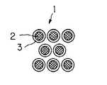
本実施の形態に係る蛍光体の一例を図1に模式的に示す。この蛍光体1は、蛍光体粒子2の周囲が、ガラス成分3によって覆われている。
【0015】
この蛍光体粒子2は、付活剤がドープされた硫化亜鉛からなり、その粒径は約3nm程度である。硫化亜鉛に付活剤をドープさせることで、励起子、電子及び正孔対を数nmの範囲に閉じこめることができる量子サイズ効果を発生させ、広いバンドギャップを有するものとなる。
【0016】
このような、硫化亜鉛にドープされる付活剤としては、テルビウム(Tb)、ユーロピウム(Eu)、フッ素(F)等を挙げることができる。これらの付活剤は、硫化亜鉛にドープされると、固有の発色性をもつ。具体的に、例えばTb及びTbF3は緑色の発光及び残光を示す。また、Eu及びEuF3は赤色の発光及び残光を示す。
【0017】
さらに、この蛍光体粒子2は、その周囲がガラス成分3によって覆われている。蛍光体粒子2の周囲をガラス成分3によって覆うことで、電子線励起において発光効率を上げることができる。このガラス成分3は、(−SiO−)nで表される。
【0018】
従って、本実施の形態に係る蛍光体1は、光吸収及び発光特性の向上が達成されたものとなる。そして、このような蛍光体1は、つぎに示すようにして製造される。なお、以下の説明においては、Tbがドープされた硫化亜鉛をZnS:Tbのように表記する。
【0019】
まず、共沈を利用した液相反応にて、付活剤がドープされた硫化亜鉛からなる蛍光体粒子2を形成する。
【0020】
ここで、共沈を利用した液相反応とは、所定の溶媒中で硫化亜鉛を合成するに際して、付活剤となる原子を有する塩を反応系に共存させる反応である。なお、このとき、硫化亜鉛にドープされる付活剤としては、1種類の原子である必要はなく、複数種類の原子からなるものであってもよい。
【0021】
具体的には、ZnS:Tbを製造する際には、下記のような液相反応となる。
【0022】
【化1】
以上のような反応により、付活剤としてTbがドープされた硫化亜鉛からなる蛍光体粒子ZnS:Tbが得られる。なお、本方法において、付活剤は、塩として液相反応中に添加される。このとき付活剤となる原子を有する塩としては、その原子の種類に応じて酢酸塩、硝酸塩、硫酸鉛等を挙げることができる。
【0024】
次に、得られた蛍光体粒子2と、ガラス成分3とを反応させて、蛍光体粒子2の周囲をガラス成分3でコーティングして蛍光体1を得る。
【0025】
このガラス成分3は、次式に示すように、テトラエトキキシシランをエタノール、イオン交換水、塩酸中で重合して得られたゲルからなる。
【0026】
【化2】
そして、ZnS:Tbからなる蛍光体粒子2とガラス成分3とを反応させて、蛍光体粒子2の周囲をガラス成分3でコーティングする際には、下記のような反応となる。
【0028】
【化3】
このようにして、付活剤がドープされた硫化亜鉛からなる蛍光体粒子2の周囲が、ガラス成分3によって覆われてなる蛍光体1が得られる。
【0030】
さらに、この蛍光体1に対して紫外線を照射する紫外線照射処理を施すことが好ましい。蛍光体1に対して紫外線照射処理を施すことで、蛍光体1の電子線励起における発光効率をさらに高めることができる。
【0031】
なお、上記の説明では付活剤としてTbを用いたZnS:Tbからなる蛍光体粒子2の周囲をガラス成分3でコーティングして蛍光体1を得る場合の製造方法について説明したが、他の付活剤を用いた場合にも、上記と同様にして蛍光体1を得ることができる。
【0032】
具体的には、付活剤としてTbF3がドープされた硫化亜鉛ZnS:TbF3を製造する際には、下記のような液相反応となる。
【0033】
【化4】
そして、ZnS:TbF3からなる蛍光体粒子2の周囲をガラス成分3でコーティングする際には、下記のような反応となる。
【0035】
【化5】
このようにして、付活剤がドープされた硫化亜鉛からなる蛍光体粒子2の周囲が、ガラス成分3によって覆われてなる蛍光体1が得られる。
【0037】
さらに、この蛍光体1に対して紫外線を照射する紫外線照射処理を施すことが好ましい。蛍光体1に対して紫外線照射処理を施すことで、蛍光体1の電子線励起における発光効率をさらに高めることができる。
【0038】
また、付活剤としてEuがドープされた硫化亜鉛ZnS:Euを製造する際には、下記のような液相反応となる。
【0039】
【化6】
そして、ZnS:Euからなる蛍光体粒子2の周囲をガラス成分3でコーティングする際には、下記のような反応となる。
【0041】
【化7】
このようにして、付活剤がドープされた硫化亜鉛からなる蛍光体粒子2の周囲が、ガラス成分3によって覆われてなる蛍光体1が得られる。
【0043】
さらに、この蛍光体1に対して紫外線を照射する紫外線照射処理を施すことが好ましい。蛍光体1に対して紫外線照射処理を施すことで、蛍光体1の電子線励起における発光効率をさらに高めることができる。
【0044】
また、付活剤としてEuF3がドープされた硫化亜鉛ZnS:EuF3を製造する際には、下記のような液相反応となる。
【0045】
【化8】
そして、ZnS:EuF3からなる蛍光体粒子2の周囲をガラス成分3でコーティングする際には、下記のような反応となる。
【0047】
【化9】
このようにして、付活剤がドープされた硫化亜鉛からなる蛍光体粒子2の周囲が、ガラス成分3によって覆われてなる蛍光体1が得られる。
【0049】
さらに、この蛍光体1に対して紫外線を照射する紫外線照射処理を施すことが好ましい。蛍光体1に対して紫外線照射処理を施すことで、蛍光体1の電子線励起における発光効率をさらに高めることができる。
【0050】
【実施例】
本発明にかかる蛍光体の製造方法を用いて、ナノクリスタル蛍光体を作製した。
【0051】
〈実施例1〉
まず、付活剤としてTbを用いた場合を示す。以下にZnS:Tbの製造工程を示す。
【0052】
まず、テトラエトキシシラン50gを、エタノール76.6g、イオン交換水46.6g、塩酸(12規定)1.5g中で70時間、50℃で重合させた。そして、重合してできたゲルを12.5g量り取り、50gのイオン交換水中で3時間撹拌した。これによりガラス成分の原料が作製された。
【0053】
次に、酢酸亜鉛のメタノール溶液(0.133mol/l)を100mlと硝酸テルビウムのメタノール溶液(0.024mol/l)を16.6mlとをマグネチックスターラーを用いて撹拌し、混合溶液を得た。そして、この混合溶液を、マグネチックスターラーを用いて撹拌している状態の硫化ナトリウムの水溶液(0.48mol/l)33.3mlに添加し、さらに激しく20分間撹拌した。
【0054】
次に、上記のガラス成分の原料を、20分間撹拌した共沈溶液に添加し、さらに20分間撹拌した。この後、遠心分離器を用いて、3000rpmで20分間遠心分離を行い、沈殿物を得た。そして、この沈殿物を80℃で24時間送風乾燥し、得られた固体物を粉砕した後、さらに80℃72時間で送風乾燥することによりZnS:Tbを得た。
【0055】
なお、ここでは硝酸テルビウムのメタノール溶液は2.77ml〜27.7mlの範囲で添加されることが好ましい。つまり、TbはZnの1molに対して0.5mol%〜5mol%の割合で添加されることが好ましく、3mol%が最適である。また、ガラス成分の原料の添加量は、重合してできたゲルが5g〜25g、イオン交換水20g〜100gの範囲が好ましく、(濃度は何れも20%)、ゲル12.5g、イオン交換水50gが最適である。
【0056】
上記のナノクリスタル蛍光体ZnS:Tbの、電子線励起5kV、50μA条件下での発光スペクトルを図2に示す。Tb3+の5D4→7F5の緑色発光が543nmに観測できる。また、上記蛍光体の輝度は、ガラス成分が無いときに比べて10倍以上高い値を示した。また、粒径は透過型電子顕微鏡写真(TEM:transmission electron microscopy)観察より約3nmであった。
【0057】
〈実施例2〉
付活剤としてTb、Fを用いた場合を示す。以下にZnS:TbF3の製造工程を示す。
【0058】
まず、上述の実施例1と同様にしてガラス成分の原料を作製した。
【0059】
次に、酢酸亜鉛のメタノール溶液(0.133mol/l)100mlと硝酸テルビウムのメタノール溶液(0.024mol/l)16.6mlとフッ化ナトリウムの水溶液(0.072mol/l)16.6mlとをマグネチックスターラーを用いて撹拌して混合溶液を得た。そして、この混合溶液を、マグネチックスターラーを用いて撹拌している状態の硫化ナトリウムの水溶液(0.48mol/l)33.3mlに添加し、さらに激しく20分間撹拌した。
【0060】
次に、上記のガラス成分の原料を、20分間撹拌した共沈溶液に添加し、さらに20分間撹拌した。この後、遠心分離器を用いて、3000rpmで20分間遠心分離を行い、沈殿物を得た。そして、この沈殿物を80℃で24時間風乾燥し、得られた固体物を粉砕した後、さらに80℃72時間で送風乾燥することによりZnS:TbF3を得た。
【0061】
なお、ここでは硝酸テルビウムのメタノール溶液は2.77ml〜27.7mlの範囲で添加されることが好ましく、また、フッ化ナトリウムの水溶液も2.77ml〜27.7mlの範囲で添加されることが好ましい。つまり、TbはZnの1molに対して0.5mol%〜5mol%の割合で、Fは1.5mol%〜15mol%の割合で添加されることが好ましく、Tbは3mol%が、Fは9mol%が最適である。また、ガラス成分の原料の添加量は、重合してできたゲルが5g〜25g、イオン交換水20g〜100gの範囲が好ましく、(濃度は何れも20%)、ゲル12.5g、イオン交換水50gが最適である。
【0062】
上記のナノクリスタル蛍光体ZnS:TbF3の電子線励起5kV、50μA条件下での発光スペクトルから、Tb3+の5D4→7F5の緑色発光が543nmに観測できる。また、上記蛍光体の輝度はガラス成分が無いときに比べて10倍以上高い値を示した。また、粒径はTEM観察より約3nmであった。
【0063】
さらに、ZnS:TbF3はZnS:Tbに比べて2.5倍以上の明るさを示す。電荷補償を考慮してFを添加することにより、発光効率が高くなることがわかる。
【0064】
〈実施例3〉
付活剤としてEuを用いた場合を示す。以下にZnS:Euの製造工程を示す。
【0065】
まず、上述の実施例1と同様にしてガラス成分の原料を作製した。
【0066】
次に、酢酸亜鉛のメタノール溶液(0.133mol/l)100mlと硝酸ユーロピウムのメタノール溶液(0.024mol/l)16.6mlとをマグネチックスターラーを用いて撹拌して混合溶液を得た。そして、この混合溶液を、マグネチックスターラーを用いて撹拌している状態の硫化ナトリウムの水溶液(0.48mol/l)33.3mlに添加して、さらに激しく20分間撹拌した。
【0067】
次に、上記のガラス成分の原料を、20分間撹拌した共沈溶液に添加し、さらに20分間撹拌した。この後、遠心分離器を用いて、3000rpmで20分間遠心分離を行い、沈殿物を得た。そして、この沈殿物を80℃で24時間送風乾燥して得られた固体物を粉砕した後、さらに80℃72時間で送風乾燥することによりZnS:Euを得た。
【0068】
なお、ここでは硝酸ユーロピウムのメタノール溶液は2.77ml〜27.7mlの範囲で添加されることが好ましい。つまり、EuはZnの1molに対して0.5mol%〜5mol%の割合で添加されることが好ましく、3mol%が最適である。また、ガラス成分の原料の添加量は、重合してできたゲルが5g〜25g、イオン交換水20g〜100gの範囲が好ましく、(濃度は何れも20%)、ゲル12.5g、イオン交換水50gが最適である。
【0069】
上記のナノクリスタル蛍光体ZnS:Euの、電子線励起5kV、50μA条件下での発光スペクトルを図3に示す。Eu3+の5D0→7F2の赤色発光が616nmに観測できる。また、上記蛍光体の輝度はガラス成分が無いときに比べて5倍以上高い値を示した。また、粒径はTEM観察より約3nmであった。
【0070】
〈実施例4〉
付活剤としてEu、Fを用いた場合を示す。以下にZnS:EuF3の製造工程を示す。
【0071】
まず、上述の実施例1と同様にしてガラス成分の原料を作製した。
【0072】
次に、酢酸亜鉛のメタノール溶液(0.133mol/l)100mlと硝酸ユーロピウムのメタノール溶液(0.024mol/l)16.6mlとフッ化ナトリウムの水溶液(0.072mol/l)16.6mlとをマグネチックスターラーを用いて撹拌して混合溶液を得た。そして、この混合溶液を、マグネチックスターラーを用いて撹拌している状態の硫化ナトリウムの水溶液(0.48mol/l)33.3mlに添加して、さらに激しく20分間撹拌した。
【0073】
上記のガラス成分の原料を、20分間撹拌した共沈溶液に添加し、さらに20分間撹拌した。この後、遠心分離器を用いて、3000rpmで20分間遠心分離を行い、沈殿物を得た。そして、この沈殿物を80℃で24時間送風乾燥して得られた固体物を粉砕した後、さらに80℃72時間で送風乾燥することによりZnS:EuF3を得た。
【0074】
ここでは硝酸ユーロピウムのメタノール溶液は2.77ml〜27.7mlの範囲で添加されることが好ましく、また、フッ化ナトリウムの水溶液も2.77ml〜27.7mlの範囲で添加されることが好ましい。つまり、EuはZnの1molに対して0.5mol%〜5mol%の割合で、Fは1.5mol%〜15mol%の割合で添加されることが好ましく、Euは3mol%が、Fは9mol%が最適である。また、ガラス成分の原料の添加量は、重合してできたゲルが5g〜25g、イオン交換水20g〜100gの範囲が好ましく、(濃度は何れも20%)、ゲル12.5g、イオン交換水50gが最適である。
【0075】
上記のナノクリスタル蛍光体ZnS:EuF3の電子線励起5kV、50μA条件下での発光スペクトルから、Eu3+の5D0→7F2の赤色発光が616nmに観測できる。また、上記蛍光体の輝度はガラス成分が無いときに比べて5倍以上高い値を示した。また、粒径はTEM観察より約3nmであった。
【0076】
さらに、ZnS:EuF3はZnS:Euに比べて2.7倍以上の明るさを示す。電荷補償を考慮してFを添加することにより、発光効率が高くなることがわかる。
【0077】
以下に示す実験例5〜実施例8では、蛍光体に対して紫外線処理を行った場合の効果について調べた。
【0078】
〈実施例5〉
まず、付活剤としてTbを用いた場合を示す。
【0079】
まず、上述した実施例1と同様にして、周囲がガラス成分でコーティングされてなるZnS:Tbを得た。
【0080】
次に、得られたZnS:Tbに対して、出力150Wの紫外線照射装置を用いて、波長379nmの紫外線を5時間照射することにより、ナノクリスタル蛍光体ZnS:Tbを得た。
【0081】
なお、ここでは、照射する紫外線の波長は365nm〜385nmの範囲が好ましく、最も好ましい波長は379nmである。また、紫外線の照射時間は、出力150Wの紫外線照射装置を用いた場合に、5時間以上とすることが好ましい。
【0082】
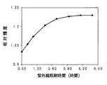
上記のナノクリスタル蛍光体ZnS:Tbの、電子線励起5kV、50μA条件下での発光スペクトルを図4に示す。Tb3+の5D4→7F5の緑色発光が543nmに観測できる。また、紫外線照射時間に対する相対輝度を図5に示す。紫外線を5時間照射した蛍光体の輝度は、紫外線を照射しないときに比べて1.28倍高い値を示した。また、粒径はTEM観察より約3nmであった。
【0083】
〈実施例6〉
付活剤としてTb、Fを用いた場合を示す。
【0084】
まず、上述した実施例2と同様にして、周囲がガラス成分でコーティングされてなるZnS:TbF3を得た。
【0085】
次に、得られたZnS:TbF3に対して、出力150Wの紫外線照射装置を用いて、波長379nmの紫外線を5時間照射することにより、ナノクリスタル蛍光体ZnS:Tbを得た。
【0086】
なお、ここでは、照射する紫外線の波長は365nm〜385nmの範囲が好ましく、最も好ましい波長は379nmである。また、紫外線の照射時間は、出力150Wの紫外線照射装置を用いた場合に、5時間以上とすることが好ましい。
【0087】
上記のナノクリスタル蛍光体ZnS:TbF3の電子線励起5kV、50μA条件下での発光スペクトルから、Tb3+の5D4→7F5の緑色発光が543nmに観測できる。また、紫外線を5時間照射した蛍光体の輝度は、紫外線を照射しないときに比べて1.3倍高い値を示した。また、粒径はTEM観察より約3nmであった。
【0088】
さらに、ZnS:TbF3はZnS:Tbに比べて2.5倍以上の明るさを示す。紫外線を照射した場合においても、電荷補償を考慮してFを添加することにより、発光効率が高くなることがわかる。
【0089】
〈実施例7〉
まず、付活剤としてEuを用いた場合を示す。
【0090】
まず、上述した実施例3と同様にして、周囲がガラス成分でコーティングされてなるZnS:Euを得た。
【0091】
次に、得られたZnS:Euに対して、出力150Wの紫外線照射装置を用いて、波長379nmの紫外線を5時間照射することにより、ナノクリスタル蛍光体ZnS:Tbを得た。
【0092】
なお、ここでは、照射する紫外線の波長は365nm〜385nmの範囲が好ましく、最も好ましい波長は379nmである。また、紫外線の照射時間は、出力150Wの紫外線照射装置を用いた場合に、5時間以上とすることが好ましい。
【0093】
上記のナノクリスタル蛍光体ZnS:Euの、電子線励起5kV、50μA条件下での発光スペクトルを図6に示す。Eu3+の5D0→7F2の赤色発光が616nmに観測できる。また、紫外線照射時間に対する相対輝度を図7に示す。紫外線を5時間照射した蛍光体の輝度は、紫外線を照射しないときに比べて1.35倍高い値を示した。また、粒径はTEM観察より約3nmであった。
【0094】
〈実施例8〉
付活剤としてEu、Fを用いた場合を示す。
【0095】
まず、上述した実施例4と同様にして、周囲がガラス成分でコーティングされてなるZnS:EuF3を得た。
【0096】
次に、得られたZnS:EuF3に対して、出力150Wの紫外線照射装置を用いて、波長379nmの紫外線を5時間照射することにより、ナノクリスタル蛍光体ZnS:Euを得た。
【0097】
なお、ここでは、照射する紫外線の波長は365nm〜385nmの範囲が好ましく、最も好ましい波長は379nmである。また、紫外線の照射時間は、出力150Wの紫外線照射装置を用いた場合に、5時間以上とすることが好ましい。
【0098】
上記のナノクリスタル蛍光体ZnS:EuF3の電子線励起5kV、50μA条件下での発光スペクトルから、Eu3+の5D0→7F2の赤色発光が616nmに観測できる。また、紫外線を5時間照射した蛍光体の輝度は、紫外線を照射しないときに比べて1.36倍高い値を示した。また、粒径はTEM観察より約3nmであった。
【0099】
さらに、ZnS:EuF3はZnS:Euに比べて2.7倍以上の明るさを示す。紫外線を照射した場合においても、電荷補償を考慮してFを添加することにより、発光効率が高くなることがわかる。
【0100】
上述した実施例5〜実施例8から、ナノクリスタル蛍光体に対して紫外線を照射することにより、当該ナノクリスタル蛍光体の電子線励起における発光強度を向上できることがわかった。
【0101】
【発明の効果】
本発明では、蛍光体粒子の周囲をガラス成分で覆い、必要に応じてさらに紫外線を照射することにより、電子線励起において発光光度が向上した蛍光体を得ることができる。
【0102】
従って、本発明では、ナノサイズといった超微細であり、低電圧でも励起発光することが可能で、さらに発光効率の高い蛍光体を実現することができ、これらの蛍光体は、FEDや高精細CRTに特に適したものとなる。
【図面の簡単な説明】
【図1】本発明にかかる蛍光体粒子の構成例を示す断面図である。
【図2】実施例1で作製した蛍光体粒子の発光スペクトル図である。
【図3】実施例3で作製した蛍光体粒子の発光スペクトル図である。
【図4】実施例5で作製した蛍光体粒子の発光スペクトル図である。
【図5】実施例5で作製した蛍光体粒子について、紫外線照射時間と相対輝度との関係を示す図である。
【図6】実施例7で作製した蛍光体粒子の発光スペクトル図である。
【図7】実施例7で作製した蛍光体粒子について、紫外線照射時間と相対輝度との関係を示す図である。
【符号の説明】
1 蛍光体、 2 蛍光体粒子、 3 ガラス成分[0001]
BACKGROUND OF THE INVENTION
The present invention relates to phosphor particles and a method for producing the same.
[0002]
[Prior art]
In recent years, attention has been focused on nanostructure crystals exhibiting specific optical characteristics in II-VI group semiconductors such as ultrafine particles such as Si and Ge, and porous silicon. Here, the nanostructure crystal means a crystal grain having a particle size of about several nanometers, and is generally called a nanocrystal.
[0003]
In the II-VI group semiconductor, when the nanostructure crystal as described above is compared with the case of having a bulk crystal, when the nanostructure crystal is included, good light absorption characteristics and light emission characteristics are exhibited. It will be. This is presumably because a II-VI group semiconductor having a nanostructure crystal has a larger band gap than a bulk crystal structure because a quantum size effect is exhibited. That is, in the II-VI group semiconductors having nanostructure crystals, it is considered that the band gap may be widened by the quantum size effect.
[0004]
By the way, various phosphors are used in displays such as televisions. At present, the particle size of a phosphor used in a display such as a television is about several microns (3 to 10 μm). In recent years, various displays have been developed, and plasma displays (PDPs), field emission displays (FEDs), and electroluminescence displays (ELDs) have attracted particular attention from the viewpoint of thinning.
[0005]
Among them, in the FED which is particularly attracting attention, it is necessary to reduce the voltage of the electron beam when the thickness is reduced. However, in a thin display, when a phosphor having a particle size of about several μm as described above is used, the voltage of the electron beam is low, so that it does not emit light sufficiently. That is, such a thin display cannot sufficiently excite a conventional phosphor. This is because the conventional phosphor crystal is large and the irradiated electron beam cannot reach the light emitting portion of the light emitter. That is, a conventional phosphor having a particle size of about several μm does not emit light sufficiently when used in a thin display. Therefore, it can be said that phosphors that can be excited at a low voltage are suitable for thin displays, particularly FEDs. Examples of the phosphor satisfying such conditions include II-VI group semiconductors having the nanostructure crystals as described above.
[0006]
Further, in the field of CRT, higher definition is progressing, and a finer phosphor is required. As a phosphor satisfying such conditions, II-VI having the above-described nanostructure crystal is provided. Group semiconductors can be mentioned.
[0007]
[Problems to be solved by the invention]
However, at present, there are only ZnO: Zn emitting blue-green light as a phosphor that can be excited at a low voltage. The manufacturing method of the II-VI group semiconductor which has a nano structure crystal is not fully examined, and a desired fluorescent substance cannot be manufactured. For this reason, a method for producing a phosphor suitable for a thin display is desired. In addition, a method for producing a fine phosphor for ultra-high definition CRT is also desired.
[0008]
The present invention has been proposed in view of such a conventional situation, and an object of the present invention is to provide a phosphor that can be excited at a low voltage and is suitable for a thin display, and a method for manufacturing the same. To do.
[0009]
[Means for Solving the Problems]
The phosphor of the present invention isSynthesized by liquid phase reaction using coprecipitationThe phosphor particles having nanostructure crystals are coated with a glass component.
In addition, the phosphor of the present invention is characterized in that phosphor particles having nanostructure crystals made of zinc sulfide activated by terbium are coated with a glass component.
In addition, the phosphor of the present invention is characterized in that phosphor particles having nanostructure crystals made of zinc sulfide activated by terbium and fluorine are coated with a glass component.
In addition, the phosphor of the present invention is characterized in that phosphor particles having nanostructure crystals made of zinc sulfide activated by europium are coated with a glass component.
In addition, the phosphor of the present invention is characterized in that phosphor particles having nanostructure crystals made of zinc sulfide activated by europium and fluorine are coated with a glass component.
In addition, the phosphor of the present invention is characterized in that phosphor particles having nanostructure crystals are coated with a glass component and subjected to ultraviolet irradiation treatment.
In addition, the phosphor of the present invention is characterized in that phosphor particles having nanostructure crystals made of zinc sulfide activated by europium or terbium are coated with a glass component.
Further, the phosphor of the present invention is characterized in that the periphery of phosphor particles having nanostructure crystals made of europium and fluorine or zinc sulfide activated by terbium and fluorine is coated with a glass component. .
[0010]
In the phosphor according to the present invention as described above, since the periphery of the phosphor particles is coated with a glass component, the luminous efficiency is improved in the electron beam excitation.
[0011]
The phosphor production method of the present invention includes a first step of obtaining phosphor particles by a liquid phase reaction utilizing coprecipitation, and reacting the phosphor particles with a gel glass component, A second step of covering the periphery of the phosphor particles with a glass component, and in the second step, the gel glass component polymerizes tetraethoxysilane in ethanol, ion-exchanged water, and hydrochloric acid. It is obtained by the above.
[0012]
In the method for producing a phosphor according to the present invention as described above, phosphor particles are obtained by a liquid phase reaction in the first step and further reacted with a gel glass component in the second step. Is coated with a glass component, so that a phosphor having good luminous efficiency in electron beam excitation can be obtained.
[0013]
DETAILED DESCRIPTION OF THE INVENTION
Embodiments of the present invention will be described below.
[0014]
An example of the phosphor according to the present embodiment is schematically shown in FIG. In the
[0015]
The
[0016]
Examples of the activator doped in zinc sulfide include terbium (Tb), europium (Eu), and fluorine (F). These activators have inherent color development when doped into zinc sulfide. Specifically, for example, Tb and TbFThreeIndicates green emission and afterglow. Eu and EuFThreeIndicates red emission and afterglow.
[0017]
Further, the
[0018]
Therefore, the
[0019]
First,
[0020]
Here, the liquid phase reaction utilizing coprecipitation is a reaction in which a salt having an atom serving as an activator coexists in a reaction system when synthesizing zinc sulfide in a predetermined solvent. At this time, the activator doped in zinc sulfide need not be one kind of atom, and may be composed of a plurality of kinds of atoms.
[0021]
Specifically, when producing ZnS: Tb, the following liquid phase reaction is performed.
[0022]
[Chemical 1]
By the reaction as described above, phosphor particles ZnS: Tb made of zinc sulfide doped with Tb as an activator are obtained. In this method, the activator is added as a salt during the liquid phase reaction. Examples of the salt having an atom serving as an activator include acetate, nitrate, lead sulfate and the like according to the type of the atom.
[0024]
Next, the obtained
[0025]
As shown in the following formula, the
[0026]
[Chemical 2]
Then, when the
[0028]
[Chemical 3]
In this way, the
[0030]
Furthermore, it is preferable to perform an ultraviolet irradiation process for irradiating the
[0031]
In the above description, the manufacturing method in the case of obtaining the
[0032]
Specifically, TbF as an activatorThree-Doped zinc sulfide ZnS: TbFThreeWhen the is produced, the following liquid phase reaction occurs.
[0033]
[Formula 4]
And ZnS: TbFThreeWhen the periphery of the
[0035]
[Chemical formula 5]
In this way, the
[0037]
Furthermore, it is preferable to perform an ultraviolet irradiation process for irradiating the
[0038]
Further, when producing zinc sulfide ZnS: Eu doped with Eu as an activator, the following liquid phase reaction is performed.
[0039]
[Chemical 6]
And when the circumference | surroundings of the
[0041]
[Chemical 7]
In this way, the
[0043]
Furthermore, it is preferable to perform an ultraviolet irradiation process for irradiating the
[0044]
Also, EuF as an activatorThreeSulfide zinc doped with ZnS: EuFThreeWhen the is produced, the following liquid phase reaction occurs.
[0045]
[Chemical 8]
And ZnS: EuFThreeWhen the periphery of the
[0047]
[Chemical 9]
In this way, the
[0049]
Furthermore, it is preferable to perform an ultraviolet irradiation process for irradiating the
[0050]
【Example】
A nanocrystal phosphor was produced using the phosphor production method according to the present invention.
[0051]
<Example 1>
First, the case where Tb is used as an activator is shown. The manufacturing process of ZnS: Tb is shown below.
[0052]
First, 50 g of tetraethoxysilane was polymerized at 50 ° C. for 70 hours in 76.6 g of ethanol, 46.6 g of ion-exchanged water, and 1.5 g of hydrochloric acid (12 N). Then, 12.5 g of the gel formed by polymerization was weighed and stirred in 50 g of ion-exchanged water for 3 hours. Thereby, the raw material of the glass component was produced.
[0053]
Next, 100 ml of a methanol solution of zinc acetate (0.133 mol / l) and 16.6 ml of a methanol solution of terbium nitrate (0.024 mol / l) were stirred using a magnetic stirrer to obtain a mixed solution. . Then, this mixed solution was added to 33.3 ml of an aqueous solution of sodium sulfide (0.48 mol / l) in a state of being stirred using a magnetic stirrer, and further vigorously stirred for 20 minutes.
[0054]
Next, the glass component raw material was added to the coprecipitation solution stirred for 20 minutes and further stirred for 20 minutes. Then, it centrifuged at 3000 rpm for 20 minutes using the centrifuge, and obtained the deposit. Then, the precipitate was blown and dried at 80 ° C. for 24 hours, and the obtained solid matter was pulverized and further blown and dried at 80 ° C. for 72 hours to obtain ZnS: Tb.
[0055]
Here, the methanol solution of terbium nitrate is preferably added in a range of 2.77 ml to 27.7 ml. That is, Tb is preferably added at a ratio of 0.5 mol% to 5 mol% with respect to 1 mol of Zn, and 3 mol% is optimal. Moreover, the addition amount of the raw material of a glass component has the preferable range of 5g-25g of the gel formed by polymerization, and 20g-100g of ion-exchange water (all are 20% of a density | concentration), 12.5g of gel, ion-exchange water 50 g is optimal.
[0056]
FIG. 2 shows an emission spectrum of the nanocrystal phosphor ZnS: Tb under electron beam excitation 5 kV and 50 μA conditions. Tb3+ofFiveDFour→7FFiveGreen emission can be observed at 543 nm. Moreover, the brightness | luminance of the said fluorescent substance showed the value 10 times or more higher than the case where there is no glass component. Moreover, the particle diameter was about 3 nm from transmission electron microscope (TEM) observation.
[0057]
<Example 2>
The case where Tb and F are used as the activator is shown. ZnS: TbF belowThreeThe manufacturing process of is shown.
[0058]
First, a glass component material was prepared in the same manner as in Example 1 described above.
[0059]
Next, 100 ml of a methanol solution of zinc acetate (0.133 mol / l), 16.6 ml of a methanol solution of terbium nitrate (0.024 mol / l) and 16.6 ml of an aqueous solution of sodium fluoride (0.072 mol / l) were added. A mixed solution was obtained by stirring using a magnetic stirrer. Then, this mixed solution was added to 33.3 ml of an aqueous solution of sodium sulfide (0.48 mol / l) in a state of being stirred using a magnetic stirrer, and further vigorously stirred for 20 minutes.
[0060]
Next, the glass component raw material was added to the coprecipitation solution stirred for 20 minutes and further stirred for 20 minutes. Then, it centrifuged at 3000 rpm for 20 minutes using the centrifuge, and obtained the deposit. Then, this precipitate was air-dried at 80 ° C. for 24 hours, and the obtained solid matter was pulverized and further blown and dried at 80 ° C. for 72 hours to obtain ZnS: TbF.ThreeGot.
[0061]
Here, the methanol solution of terbium nitrate is preferably added in the range of 2.77 ml to 27.7 ml, and the aqueous solution of sodium fluoride is preferably added in the range of 2.77 ml to 27.7 ml. preferable. That is, Tb is preferably added in a proportion of 0.5 mol% to 5 mol% with respect to 1 mol of Zn, F is preferably added in a proportion of 1.5 mol% to 15 mol%, Tb is 3 mol%, and F is 9 mol%. Is the best. Moreover, the addition amount of the raw material of a glass component has the preferable range of 5g-25g of the gel formed by polymerization, and 20g-100g of ion-exchange water (all are 20% of a density | concentration), 12.5g of gel, ion-exchange water 50 g is optimal.
[0062]
Nanocrystal phosphor ZnS: TbFThreeFrom the emission spectrum of 5 kV, 50 μA under the excitation of electron beam, Tb3+ofFiveDFour→7FFiveGreen emission can be observed at 543 nm. Moreover, the brightness | luminance of the said fluorescent substance showed the value 10 times or more higher than the case where there is no glass component. The particle size was about 3 nm from TEM observation.
[0063]
Furthermore, ZnS: TbFThreeIndicates a brightness 2.5 times or more that of ZnS: Tb. It can be seen that the luminous efficiency is increased by adding F in consideration of charge compensation.
[0064]
<Example 3>
The case where Eu is used as an activator is shown. The manufacturing process of ZnS: Eu is shown below.
[0065]
First, a glass component material was prepared in the same manner as in Example 1 described above.
[0066]
Next, 100 ml of a methanol solution of zinc acetate (0.133 mol / l) and 16.6 ml of a methanol solution of europium nitrate (0.024 mol / l) were stirred using a magnetic stirrer to obtain a mixed solution. Then, this mixed solution was added to 33.3 ml of an aqueous solution of sodium sulfide (0.48 mol / l) in a state of being stirred using a magnetic stirrer, and further stirred vigorously for 20 minutes.
[0067]
Next, the glass component raw material was added to the coprecipitation solution stirred for 20 minutes and further stirred for 20 minutes. Then, it centrifuged at 3000 rpm for 20 minutes using the centrifuge, and obtained the deposit. The precipitate was blown and dried at 80 ° C. for 24 hours, pulverized, and further blown and dried at 80 ° C. for 72 hours to obtain ZnS: Eu.
[0068]
Here, the methanol solution of europium nitrate is preferably added in a range of 2.77 ml to 27.7 ml. That is, Eu is preferably added at a ratio of 0.5 mol% to 5 mol% with respect to 1 mol of Zn, and 3 mol% is optimal. Moreover, the addition amount of the raw material of a glass component has the preferable range of 5g-25g of the gel formed by polymerization, and 20g-100g of ion-exchange water (all are 20% of a density | concentration), 12.5g of gel, ion-exchange water 50 g is optimal.
[0069]
FIG. 3 shows an emission spectrum of the above nanocrystal phosphor ZnS: Eu under the conditions of electron beam excitation 5 kV and 50 μA. Eu3+ofFiveD0→7F2Red emission can be observed at 616 nm. Moreover, the brightness | luminance of the said fluorescent substance showed the value 5 times or more higher than the case where there is no glass component. The particle size was about 3 nm from TEM observation.
[0070]
<Example 4>
The case where Eu and F are used as an activator is shown. Below ZnS: EuFThreeThe manufacturing process of is shown.
[0071]
First, a glass component material was prepared in the same manner as in Example 1 described above.
[0072]
Next, 100 ml of a methanol solution of zinc acetate (0.133 mol / l), 16.6 ml of a methanol solution of europium nitrate (0.024 mol / l) and 16.6 ml of an aqueous solution of sodium fluoride (0.072 mol / l) were added. A mixed solution was obtained by stirring using a magnetic stirrer. Then, this mixed solution was added to 33.3 ml of an aqueous solution of sodium sulfide (0.48 mol / l) in a state of being stirred using a magnetic stirrer, and further stirred vigorously for 20 minutes.
[0073]
The raw material of the glass component was added to the coprecipitation solution stirred for 20 minutes, and further stirred for 20 minutes. Then, it centrifuged at 3000 rpm for 20 minutes using the centrifuge, and obtained the deposit. The precipitate was blown and dried at 80 ° C. for 24 hours, pulverized, and then blown and dried at 80 ° C. for 72 hours to obtain ZnS: EuF.ThreeGot.
[0074]
Here, the methanol solution of europium nitrate is preferably added in the range of 2.77 ml to 27.7 ml, and the aqueous solution of sodium fluoride is also preferably added in the range of 2.77 ml to 27.7 ml. That is, Eu is preferably added in a proportion of 0.5 mol% to 5 mol% with respect to 1 mol of Zn, F is preferably added in a proportion of 1.5 mol% to 15 mol%, Eu is 3 mol%, and F is 9 mol%. Is the best. Moreover, the addition amount of the raw material of a glass component has the preferable range of 5g-25g of the gel formed by polymerization, and 20g-100g of ion-exchange water (all are 20% of a density | concentration), 12.5g of gel, ion-exchange water 50 g is optimal.
[0075]
Nanocrystal phosphor ZnS: EuFThreeFrom the emission spectrum of the electron beam excited at 5 kV and 50 μA, Eu3+ofFiveD0→7F2Red emission can be observed at 616 nm. Moreover, the brightness | luminance of the said fluorescent substance showed the value 5 times or more higher than the case where there is no glass component. The particle size was about 3 nm from TEM observation.
[0076]
Furthermore, ZnS: EuFThreeIndicates a brightness that is at least 2.7 times that of ZnS: Eu. It can be seen that the luminous efficiency is increased by adding F in consideration of charge compensation.
[0077]
In Experimental Examples 5 to 8 shown below, the effects when the phosphors were subjected to ultraviolet treatment were examined.
[0078]
<Example 5>
First, the case where Tb is used as an activator is shown.
[0079]
First, in the same manner as in Example 1 described above, ZnS: Tb whose periphery was coated with a glass component was obtained.
[0080]
Next, the obtained ZnS: Tb was irradiated with ultraviolet light having a wavelength of 379 nm for 5 hours using an ultraviolet irradiation device having an output of 150 W, to obtain a nanocrystal phosphor ZnS: Tb.
[0081]
Here, the wavelength of the ultraviolet rays to be irradiated is preferably in the range of 365 nm to 385 nm, and the most preferable wavelength is 379 nm. In addition, the ultraviolet irradiation time is preferably 5 hours or longer when an ultraviolet irradiation device with an output of 150 W is used.
[0082]
FIG. 4 shows an emission spectrum of the nanocrystal phosphor ZnS: Tb under electron beam excitation 5 kV and 50 μA conditions. Tb3+ofFiveDFour→7FFiveGreen emission can be observed at 543 nm. Further, the relative luminance with respect to the ultraviolet irradiation time is shown in FIG. The luminance of the phosphor irradiated with ultraviolet rays for 5 hours was 1.28 times higher than that when not irradiated with ultraviolet rays. The particle size was about 3 nm from TEM observation.
[0083]
<Example 6>
The case where Tb and F are used as the activator is shown.
[0084]
First, in the same manner as in Example 2 described above, ZnS: TbF whose periphery is coated with a glass component.ThreeGot.
[0085]
Next, the obtained ZnS: TbFThreeOn the other hand, the nanocrystal phosphor ZnS: Tb was obtained by irradiating ultraviolet rays with a wavelength of 379 nm for 5 hours using an ultraviolet irradiation device with an output of 150 W.
[0086]
Here, the wavelength of the ultraviolet rays to be irradiated is preferably in the range of 365 nm to 385 nm, and the most preferable wavelength is 379 nm. In addition, the ultraviolet irradiation time is preferably 5 hours or longer when an ultraviolet irradiation device with an output of 150 W is used.
[0087]
Nanocrystal phosphor ZnS: TbFThreeFrom the emission spectrum of 5 kV, 50 μA under the excitation of electron beam, Tb3+ofFiveDFour→7FFiveGreen emission can be observed at 543 nm. In addition, the luminance of the phosphor irradiated with ultraviolet rays for 5 hours was 1.3 times higher than when not irradiated with ultraviolet rays. The particle size was about 3 nm from TEM observation.
[0088]
Furthermore, ZnS: TbFThreeIndicates a brightness 2.5 times or more that of ZnS: Tb. It can be seen that the luminous efficiency can be increased by adding F in consideration of charge compensation even when irradiated with ultraviolet rays.
[0089]
<Example 7>
First, the case where Eu is used as an activator is shown.
[0090]
First, in the same manner as in Example 3 described above, ZnS: Eu whose periphery was coated with a glass component was obtained.
[0091]
Next, the obtained ZnS: Eu was irradiated with ultraviolet light having a wavelength of 379 nm for 5 hours using an ultraviolet irradiation device having an output of 150 W, thereby obtaining a nanocrystal phosphor ZnS: Tb.
[0092]
Here, the wavelength of the ultraviolet rays to be irradiated is preferably in the range of 365 nm to 385 nm, and the most preferable wavelength is 379 nm. In addition, the ultraviolet irradiation time is preferably 5 hours or longer when an ultraviolet irradiation device with an output of 150 W is used.
[0093]
FIG. 6 shows an emission spectrum of the above nanocrystal phosphor ZnS: Eu under the conditions of electron beam excitation 5 kV and 50 μA. Eu3+ofFiveD0→7F2Red emission can be observed at 616 nm. FIG. 7 shows the relative luminance with respect to the ultraviolet irradiation time. The brightness of the phosphor irradiated with ultraviolet rays for 5 hours was 1.35 times higher than when not irradiated with ultraviolet rays. The particle size was about 3 nm from TEM observation.
[0094]
<Example 8>
The case where Eu and F are used as an activator is shown.
[0095]
First, in the same manner as in Example 4 described above, ZnS: EuF whose periphery is coated with a glass component.ThreeGot.
[0096]
Next, the obtained ZnS: EuFThreeOn the other hand, a nanocrystal phosphor ZnS: Eu was obtained by irradiating ultraviolet rays with a wavelength of 379 nm for 5 hours using an ultraviolet irradiation device with an output of 150 W.
[0097]
Here, the wavelength of the ultraviolet rays to be irradiated is preferably in the range of 365 nm to 385 nm, and the most preferable wavelength is 379 nm. In addition, the ultraviolet irradiation time is preferably 5 hours or longer when an ultraviolet irradiation device with an output of 150 W is used.
[0098]
Nanocrystal phosphor ZnS: EuFThreeFrom the emission spectrum of the electron beam excited at 5 kV and 50 μA, Eu3+ofFiveD0→7F2Red emission can be observed at 616 nm. Further, the luminance of the phosphor irradiated with ultraviolet rays for 5 hours was 1.36 times higher than when not irradiated with ultraviolet rays. The particle size was about 3 nm from TEM observation.
[0099]
Furthermore, ZnS: EuFThreeIndicates a brightness that is at least 2.7 times that of ZnS: Eu. It can be seen that the luminous efficiency can be increased by adding F in consideration of charge compensation even when irradiated with ultraviolet rays.
[0100]
From Examples 5 to 8 described above, it was found that the emission intensity of the nanocrystal phosphor in electron beam excitation can be improved by irradiating the nanocrystal phosphor with ultraviolet rays.
[0101]
【The invention's effect】
In the present invention, a phosphor having an improved luminous intensity in electron beam excitation can be obtained by covering the periphery of the phosphor particles with a glass component and further irradiating with ultraviolet rays as necessary.
[0102]
Therefore, in the present invention, it is possible to realize phosphors that are ultrafine, such as nano-size, can be excited to emit light even at a low voltage, and have higher luminous efficiency. These phosphors can be used for FEDs and high-definition CRTs. It is particularly suitable for
[Brief description of the drawings]
FIG. 1 is a cross-sectional view showing a configuration example of phosphor particles according to the present invention.
2 is an emission spectrum diagram of the phosphor particles produced in Example 1. FIG.
3 is an emission spectrum diagram of the phosphor particles produced in Example 3. FIG.
4 is an emission spectrum diagram of the phosphor particles produced in Example 5. FIG.
5 is a graph showing the relationship between ultraviolet irradiation time and relative luminance for the phosphor particles produced in Example 5. FIG.
6 is an emission spectrum diagram of the phosphor particles produced in Example 7. FIG.
7 is a graph showing the relationship between the ultraviolet irradiation time and the relative luminance for the phosphor particles produced in Example 7. FIG.
[Explanation of symbols]
1 phosphor, 2 phosphor particles, 3 glass component
Claims (14)
Translated fromJapanese上記蛍光体粒子に対してゲル状のガラス成分を反応させることにより、当該蛍光体粒子の周りをガラス成分で覆う第2の工程とを有し、
上記第2の工程において、上記ゲル状のガラス成分は、テトラエトキシシランをエタノール、イオン交換水、塩酸中で重合して得られたものであることを特徴とする蛍光体の製造方法。A first step of obtaining phosphor particles by a liquid phase reaction utilizing coprecipitation;
A second step of covering the phosphor particles with a glass component by reacting the phosphor particles with a gel-like glass component;
In the second step, the gel glass component is obtained by polymerizing tetraethoxysilane in ethanol, ion-exchanged water, and hydrochloric acid.
Priority Applications (1)
| Application Number | Priority Date | Filing Date | Title |
|---|---|---|---|
| JP08908199AJP3988309B2 (en) | 1999-01-14 | 1999-03-30 | Phosphor and method for producing the same |
Applications Claiming Priority (3)
| Application Number | Priority Date | Filing Date | Title |
|---|---|---|---|
| JP11-8039 | 1999-01-14 | ||
| JP803999 | 1999-01-14 | ||
| JP08908199AJP3988309B2 (en) | 1999-01-14 | 1999-03-30 | Phosphor and method for producing the same |
Publications (2)
| Publication Number | Publication Date |
|---|---|
| JP2000265166A JP2000265166A (en) | 2000-09-26 |
| JP3988309B2true JP3988309B2 (en) | 2007-10-10 |
Family
ID=26342454
Family Applications (1)
| Application Number | Title | Priority Date | Filing Date |
|---|---|---|---|
| JP08908199AExpired - Fee RelatedJP3988309B2 (en) | 1999-01-14 | 1999-03-30 | Phosphor and method for producing the same |
Country Status (1)
| Country | Link |
|---|---|
| JP (1) | JP3988309B2 (en) |
Families Citing this family (13)
| Publication number | Priority date | Publication date | Assignee | Title |
|---|---|---|---|---|
| DE10051242A1 (en)* | 2000-10-17 | 2002-04-25 | Philips Corp Intellectual Pty | Light-emitting device with coated phosphor |
| JP3613792B2 (en)* | 2001-10-01 | 2005-01-26 | 独立行政法人科学技術振興機構 | Solid-state self-luminous display device and manufacturing method thereof |
| WO2004000971A1 (en) | 2002-06-19 | 2003-12-31 | National Institute Of Advanced Industrial Science And Technology | Semiconductor superfine particle phosphor and light emitting device |
| WO2004007636A1 (en)* | 2002-07-16 | 2004-01-22 | Futaba Corporation | Composite nanoparticle and process for producing the same |
| JP3847677B2 (en)* | 2002-07-23 | 2006-11-22 | 日立ソフトウエアエンジニアリング株式会社 | Semiconductor nanoparticle, method for producing the same, and semiconductor nanoparticle fluorescent reagent |
| TWI273091B (en) | 2002-09-06 | 2007-02-11 | Masakazu Kobayashi | Compound semiconductor particles and production process thereof |
| DE10307281A1 (en) | 2003-02-20 | 2004-09-02 | Patent-Treuhand-Gesellschaft für elektrische Glühlampen mbH | Coated phosphor, light-emitting device with such phosphor and method for its production |
| US20060196375A1 (en)* | 2004-10-22 | 2006-09-07 | Seth Coe-Sullivan | Method and system for transferring a patterned material |
| US20090236563A1 (en) | 2006-01-27 | 2009-09-24 | Konica Minolta Medical & Graphic, Inc. | Nanosized Semiconductor Particle Having Core/Shell Structure and Manufacturing Method Thereof |
| US7431867B2 (en)* | 2006-01-27 | 2008-10-07 | Konica Minolta Medical & Graphic, Inc. | Nanosized semiconductor particles |
| JP2007308537A (en)* | 2006-05-16 | 2007-11-29 | Sony Corp | Luminous composition, light source unit and display |
| WO2008090814A1 (en) | 2007-01-22 | 2008-07-31 | Konica Minolta Medical & Graphic, Inc. | Core/shell-type semiconductor nanoparticle and method for production thereof |
| JP5371011B2 (en)* | 2007-08-28 | 2013-12-18 | 独立行政法人産業技術総合研究所 | Novel nanoparticle emitter |
- 1999
- 1999-03-30JPJP08908199Apatent/JP3988309B2/ennot_activeExpired - Fee Related
Also Published As
| Publication number | Publication date |
|---|---|
| JP2000265166A (en) | 2000-09-26 |
Similar Documents
| Publication | Publication Date | Title |
|---|---|---|
| US6447698B1 (en) | Method for producing light-emitting substance | |
| JP3988309B2 (en) | Phosphor and method for producing the same | |
| US6379583B1 (en) | Nanoparticle phosphors manufactured using the bicontinuous cubic phase process | |
| US20190031952A1 (en) | Quantum Dots Stabilized With A Metal Thiol Polymer | |
| US7394091B2 (en) | Composite nano-particle and method for preparing the same | |
| JPH10310770A (en) | Production of luminophor | |
| JPH06349579A (en) | Product and doped particle | |
| US20020081373A1 (en) | Method for preparing efficient low voltage phosphors | |
| JP4270500B2 (en) | Method for producing nanocrystal phosphor | |
| JP3755033B2 (en) | Silica-based glass particle material and device containing ultrafine semiconductor particles | |
| JP4206100B2 (en) | Yttrium-based phosphor, method for producing the same, and display element using the same | |
| JP3874508B2 (en) | Phosphor composite | |
| KR20000077178A (en) | Fluorescent material and manufacturing method therefor | |
| JP3329598B2 (en) | Phosphor, cathode ray tube, fluorescent lamp and phosphor manufacturing method | |
| JPH11293241A (en) | Phosphor and its production | |
| JP2005139372A (en) | Fluorescent substance for inorganic el, method for producing the same and fluorescent substance-dispersing type el element using the same | |
| WO2006001194A1 (en) | Fluorescent substance and process for producing the same, and particle dispersion-type el device using the same | |
| JP2005132947A (en) | Fluorophor for inorganic electroluminescence, method for producing the same, and inorganic electroluminescent device | |
| JP2005120320A (en) | Light emitter, method for producing the same, and fed and pdp devices using light emitter | |
| JP2003246978A (en) | Ultrafine fluorescent particle and luminescent product containing the same | |
| JPH0324188A (en) | Phosphor composition | |
| KR20020072868A (en) | Phosphors adhered by nano-sized phosphors, preparing process thereof and Cathode Ray Tube using the same | |
| CN119875616A (en) | Fluorescent lifetime-adjustable composite superlattice nanosphere and preparation method and application thereof | |
| CN118085853A (en) | Preparation method and application of efficient blue-light-emitting cesium bromide nanorod | |
| JP4417657B2 (en) | Method for improving fluorescence intensity of inorganic fluorescent particles |
Legal Events
| Date | Code | Title | Description |
|---|---|---|---|
| A621 | Written request for application examination | Free format text:JAPANESE INTERMEDIATE CODE: A621 Effective date:20050420 | |
| A977 | Report on retrieval | Free format text:JAPANESE INTERMEDIATE CODE: A971007 Effective date:20070117 | |
| A131 | Notification of reasons for refusal | Free format text:JAPANESE INTERMEDIATE CODE: A131 Effective date:20070123 | |
| A521 | Request for written amendment filed | Free format text:JAPANESE INTERMEDIATE CODE: A523 Effective date:20070326 | |
| TRDD | Decision of grant or rejection written | ||
| A01 | Written decision to grant a patent or to grant a registration (utility model) | Free format text:JAPANESE INTERMEDIATE CODE: A01 Effective date:20070626 | |
| A61 | First payment of annual fees (during grant procedure) | Free format text:JAPANESE INTERMEDIATE CODE: A61 Effective date:20070709 | |
| FPAY | Renewal fee payment (event date is renewal date of database) | Free format text:PAYMENT UNTIL: 20100727 Year of fee payment:3 | |
| FPAY | Renewal fee payment (event date is renewal date of database) | Free format text:PAYMENT UNTIL: 20100727 Year of fee payment:3 | |
| FPAY | Renewal fee payment (event date is renewal date of database) | Free format text:PAYMENT UNTIL: 20110727 Year of fee payment:4 | |
| FPAY | Renewal fee payment (event date is renewal date of database) | Free format text:PAYMENT UNTIL: 20120727 Year of fee payment:5 | |
| FPAY | Renewal fee payment (event date is renewal date of database) | Free format text:PAYMENT UNTIL: 20130727 Year of fee payment:6 | |
| LAPS | Cancellation because of no payment of annual fees |