JP3987465B2 - Vaporizer - Google Patents
VaporizerDownload PDFInfo
- Publication number
- JP3987465B2 JP3987465B2JP2003189112AJP2003189112AJP3987465B2JP 3987465 B2JP3987465 B2JP 3987465B2JP 2003189112 AJP2003189112 AJP 2003189112AJP 2003189112 AJP2003189112 AJP 2003189112AJP 3987465 B2JP3987465 B2JP 3987465B2
- Authority
- JP
- Japan
- Prior art keywords
- raw material
- gas
- material solution
- gas passage
- carrier gas
- Prior art date
- Legal status (The legal status is an assumption and is not a legal conclusion. Google has not performed a legal analysis and makes no representation as to the accuracy of the status listed.)
- Expired - Lifetime
Links
- 239000006200vaporizerSubstances0.000titleclaimsdescription38
- 239000007789gasSubstances0.000claimsdescription102
- 239000002994raw materialSubstances0.000claimsdescription101
- 239000012159carrier gasSubstances0.000claimsdescription58
- 230000008016vaporizationEffects0.000claimsdescription44
- 239000006185dispersionSubstances0.000claimsdescription37
- 238000009834vaporizationMethods0.000claimsdescription32
- 238000001816coolingMethods0.000claimsdescription16
- 238000010438heat treatmentMethods0.000claimsdescription13
- 239000000498cooling waterSubstances0.000claimsdescription8
- 239000000243solutionSubstances0.000description61
- 238000006243chemical reactionMethods0.000description28
- WYURNTSHIVDZCO-UHFFFAOYSA-NTetrahydrofuranChemical compoundC1CCOC1WYURNTSHIVDZCO-UHFFFAOYSA-N0.000description27
- YLQBMQCUIZJEEH-UHFFFAOYSA-NFuranChemical compoundC=1C=COC=1YLQBMQCUIZJEEH-UHFFFAOYSA-N0.000description14
- 238000000034methodMethods0.000description12
- 239000010408filmSubstances0.000description11
- 239000000047productSubstances0.000description11
- 125000002524organometallic groupChemical group0.000description9
- 239000002904solventSubstances0.000description9
- 239000000463materialSubstances0.000description8
- 239000002184metalSubstances0.000description8
- 239000001301oxygenSubstances0.000description8
- 229910052760oxygenInorganic materials0.000description8
- 239000010409thin filmSubstances0.000description8
- QVGXLLKOCUKJST-UHFFFAOYSA-Natomic oxygenChemical compound[O]QVGXLLKOCUKJST-UHFFFAOYSA-N0.000description7
- 239000007788liquidSubstances0.000description5
- 239000002245particleSubstances0.000description4
- 239000011882ultra-fine particleSubstances0.000description4
- 239000011259mixed solutionSubstances0.000description3
- 238000002156mixingMethods0.000description3
- 239000007787solidSubstances0.000description3
- 239000003990capacitorSubstances0.000description2
- 230000000694effectsEffects0.000description2
- 238000001704evaporationMethods0.000description2
- 230000008020evaporationEffects0.000description2
- 238000012986modificationMethods0.000description2
- 230000004048modificationEffects0.000description2
- 239000007800oxidant agentSubstances0.000description2
- 239000011148porous materialSubstances0.000description2
- 229910004298SiO 2Inorganic materials0.000description1
- 238000000889atomisationMethods0.000description1
- 230000015572biosynthetic processEffects0.000description1
- 238000009835boilingMethods0.000description1
- 239000005539carbonized materialSubstances0.000description1
- 239000007795chemical reaction productSubstances0.000description1
- 238000005229chemical vapour depositionMethods0.000description1
- 238000004140cleaningMethods0.000description1
- 230000000052comparative effectEffects0.000description1
- 239000013078crystalSubstances0.000description1
- 230000006837decompressionEffects0.000description1
- 238000011161developmentMethods0.000description1
- 238000010586diagramMethods0.000description1
- 238000002474experimental methodMethods0.000description1
- 239000010419fine particleSubstances0.000description1
- 239000012530fluidSubstances0.000description1
- 238000004817gas chromatographyMethods0.000description1
- 238000010574gas phase reactionMethods0.000description1
- 230000014509gene expressionEffects0.000description1
- 239000012535impuritySubstances0.000description1
- 230000010354integrationEffects0.000description1
- 230000007774longtermEffects0.000description1
- 230000014759maintenance of locationEffects0.000description1
- 150000001247metal acetylidesChemical class0.000description1
- 150000004767nitridesChemical class0.000description1
- 230000001590oxidative effectEffects0.000description1
- 229910021420polycrystalline siliconInorganic materials0.000description1
- 238000012545processingMethods0.000description1
- 238000011084recoveryMethods0.000description1
- 229920006395saturated elastomerPolymers0.000description1
- 238000010008shearingMethods0.000description1
- 229910001220stainless steelInorganic materials0.000description1
- 239000010935stainless steelSubstances0.000description1
- 239000000758substrateSubstances0.000description1
- 238000006557surface reactionMethods0.000description1
- 239000008399tap waterSubstances0.000description1
- 235000020679tap waterNutrition0.000description1
- 238000011144upstream manufacturingMethods0.000description1
- 238000005406washingMethods0.000description1
Images


Landscapes
- Chemical Vapour Deposition (AREA)
Description
Translated fromJapanese【0001】
【産業上の利用分野】
本発明は、気化器に関する。
【0002】
【発明の背景】
DRAMの開発において問題となるのは、微細化にともなう記憶キヤパシタンスである。ソフトエラーなどの点からはキャバシタンスは前の世代と同程度が要求されるため何らかの対策を必要としている。この対策として1Mまでのセル構造はプレーナ構造であったものが、4Mからスタック構造、トレンチ構造と称される立体構造が取り入れられ、キヤパシタ面積の増加を図ってきた。また誘電膜も基板Siの熱酸化膜からポリSi上で熱酸化膜とCVD窒化膜を積層する膜(この積層された膜を―般にON膜という。)が採用された。l6MDRAMでは、さらに容量に寄与する面積を増加させるため、スタック型では側面を利用する厚膜型、プレートの裏面も利用するフィン型などが取り入れられた。
【0003】
しかし、このような立体構造ではプロセスの複雑化による工程数の増加ならびに段差の増大による歩留りの低下が問題視され、256Mビット以降の実現は困難であるとされている。そのため現在のDRAMの構造を変えずに更に集積度を増加させるための1つの道として、キヤパシタンスの誘電体を誘電率の高い強誘電体のものに切り替えていく方法が考え出された。そして、誘電率の高い誘電体薄膜としてTa2O5、Y2O3、HfO2などが高誘電率単金属常誘電体酸化物の薄膜がまず注目された。それぞれの比誘電率はTa2O5が28、Y2O3が16、HfO2が24程度であり、SiO2の4〜7倍である。
【0004】
しかし256MDRAM以降での適用には、立体キャバシタ構造が必要である。これらの酸化物よりさらに高い比誘電率をもち、DRAMへの適用が期待される材料として、(BaxSr1-x)TiO3、Pb(ZryTi1-y)O3、(PbaL1-a)(ZrbTi1-b)O3の3種類が有力視されている。また、超電導材料と非常によく似た結晶構造を持つBi系の層状強誘電体材料も有望であり、特にYl材と称されるSrBi2TaO9が、低電圧駆動と疲労特性に優れている点から、近年大きく注目されている。
【0005】
一般にSrBi2TaO9強誘電体薄膜形成は、実用的かつ将来性のあるMOCVD(有機金属気相成長)法で行われている。
【0006】
強誘電体薄膜の原料は、一般的に3種類の有機金属錯体Sr(DPM)2、Bi(C6H5)3及びTa(OC2H5)5であり、それぞれTHF(テトラヒドロフラン)溶剤に溶かし、溶液として使用されている。なお、DPMはジビバイロイメタンの略である。
【0007】
それぞれの材料特性を表1に示す。
【0008】
【表1】
MOCVD法に用いる装置は、SrBi2TaO9薄膜原料を気相反応及び表面反応させ成膜を行わせる反応部、SrBi2TaO9薄膜原料並びに酸化剤を反応部へ供給する供給部、反応部での生成物を採取する回収部から構成される。
【0010】
そして、供給部は薄膜原料を気化させるための気化器が設けられている。
【0011】
従来、気化器に関する技術としては、図12に示すものが知られている。図12(a)に示すものはメタルフィルター式と称されるものであり、周囲に存在する気体とSrBi2TaO9強誘電体薄膜原料溶液との接触面積を増加させる目的で用いられたメタルフィルターに、所定の温度に加熱された原料溶液を滴下することにより気化を行う方法である。
【0012】
しかし、この技術においては、数回の気化でメタルフィルターが詰まり、長期使用に耐えられないという問題を有している。
【0013】
図12(b)は原料溶液に30kgf/cm2の圧力をかけて10μmの細孔から原料溶液を放出させ膨張によって原料溶液を気化させる技術である。
【0014】
しかし、この技術においては、数回の使用により細孔が詰まり、やはり長期の使用に耐えられないという問題を有している。
【0015】
また、原料溶液が、複数の有機金属錯体の混合溶液、例えば、Sr(DPM)2/THFとBi(C6H5)3/THFとTa(OC2H5)5/THFの混合溶液であり、この混合溶液を加熱によって気化する場合、蒸気圧の最も高い溶剤(この場合THF)がいち速く気化し、加熱面上には有機金属錯体が析出付着するため反応部への安定な原料供給ができないという問題が生ずる。
【0016】
さらに、MOCVDにおいて、均一性に優れた膜を得るためには原料溶液が均一に分散した気化ガスを得ることが要請される。しかし、上記従来技術では必ずしもかかる要請に応えきれていない。
【0017】
【発明が解決しようとする課題】
本発明は、目詰まりなどを起こすことがなく長期使用が可能であり、かつ、反応部への安定的な原料供給が可能なMOCVD用気化器を提供することを目的とする。
【0018】
本発明は、原料溶液が均一に分散した気化ガスを得ることができるMOCVD用気化器及び原料溶液の気化方法を提供することを目的とする。
【0019】
【課題を解決するための手段】
本発明の気化器は、内部に形成されたガス通路と、
前記ガス通路に加圧されたキャリアガスを導入するためのガス導入口と、
前記ガス通路に原料溶液を供給するための手段と、
原料溶液を含むキャリアガスを気化部に送るためのガス出口と、
前記ガス通路を冷却するための手段と、
を有する分散部と、
前記分散部から送られてきた、原料溶液を含むキャリアガスを加熱して気化させるための気化部と、
を有する気化器において、
前記ガス通路と、前記ガス通路に原料溶液を供給するための原料溶液の通路と、前記ガス通路及び前記原料溶液の通路とをともに冷却するための冷却水通路と、が前記分散部の内部に一体的に形成されていることを特徴とする。
【0021】
本発明の気化方法は、原料溶液を分散させたキャリアガスを気化室で気化させるための気化方法において、ガス通路内を流れる原料溶液が分散したキャリアガスを冷却することを特徴とする。
【0022】
【実施例】
(実施例1)
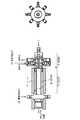
図1に実施例1に係るMOCVD用気化器を示す。
【0023】
本例では、分散部を構成する分散部本体1の内部に形成されたガス通路2と、
ガス通路2に加圧されたキャリアガス3を導入するためのガス導入口4と、
ガス通路2を通過するキャリアガスに原料溶液5を供給するための手段(原料供給孔)6と、
分散された原料溶液5を含むキャリアガスを気化部22に送るためのガス出口7と、
ガス通路2内を流れるキャリアガスを冷却するための手段(冷却水)18と、を有する分散部8と、
一端がMOCVD装置の反応管に接続され、他端が分散部8のガス出口7に接続された気化管20と、
気化管20を加熱するための加熱手段(ヒータ)21と、
を有し、前記分散部8から送られてきた、原料溶液が分散されたキャリアガスを加熱して気化させるための気化部22と、
を有する。
【0024】
以下、本実施例をより詳細に説明する。
【0025】
本例では、分散部本体1の内部に4.50mm径の孔(円筒状中空部)をあけ、その孔の中心に位置するように、孔の内径よりも大きな外径を有する(4.48mm径)ロッド10を埋め込む。分散部本体とロッド10との間に形成された空間によりガス通路2が形成される。ロッド10はビス9a,9b,9c,9dにより固定されている。なお、ガス通路2の幅は0.01mmとなる。
【0026】
なお、ガス通路の幅としては、0.005〜0.10mmが好ましい。0.005mm未満では加工が困難である。0.10mmを超えるとキャリアガスを高速化するために高圧のキャリアガスを用いる必要が生じてしまう。
【0027】
このガス通路2の一端にはガス導入口4が設けられている。ガス導入口4にはキャリアガス(例えばN2,Ar)源(図示せず)が接続されている。
【0028】
分散部本体1のほぼ中央の側部には、ガス通路2に連通せしめて原料供給孔6を設けてあり、原料溶液5をガス通路2に滴下して、原料溶液5をガス通路2を通過するキャリアガスに原料溶液5を分散させることができる。
【0029】
ガス通路2の一端には、気化部22の気化管20に連通するガス出口7が設けられている。
【0030】
分散部本体1には、冷却水18を流すための空間11が形成されており、この空間内に冷却水8を流すことによりガス通路2内を流れるキャリアガスを冷却する。あるいはこの空間の代わりに例えばペルチェ素子等を設置し冷却してもよい。分散部8のガス通路2内は気化部22のヒータ21による熱影響を受けるためガス通路2内において原料溶液の溶剤と有機金属錯体との同時気化が生ずることなく、溶剤のみの気化が生じてしまう。そこで、ガス通路2内を流れれる原料溶液が分散したキャリアガスを冷却することにより溶剤のみの気化を防止する。特に、原料供給孔6より下流側の冷却が重要であり、少なくとも原料供給孔6の下流側の冷却を行う。冷却温度は、溶剤の沸点以下の温度である。例えば、THFの場合67℃以下である。特に、ガス出口7における温度が重要である。
【0031】
また、分散部を冷却することにより、長期間にわる使用に対してもガス通路内(特にガス出口)における炭化物による閉塞を生ずることがない。
【0032】
分散部本体1の下流側において、分散部本体1は気化管20に接続されている。分散部本体1と気化管20との接続は継手24により行われ、この部分が接続部23となる。
【0033】
気化部22は気化管20と加熱手段(ヒータ)21とから構成される。ヒータ21は気化管20内を流れる原料溶液が分散したキャリアガスを加熱し気化させるためのヒータである。ヒータ21としては例えばペルチェ素子を気化管20の外周に貼り付けることにより構成すればよい。
【0034】
気化管20としては、例えばSUS316Lなどのステンレス鋼を用いることが好ましい。気化管20の寸法は適宜決定すればよいが、例えば、外径3/4インチ、長さ100mmのものを用いればよい。
【0035】
気化管20の下流側端はMOCVD装置の反応管に接続されるが、本例では気化管20に酸素供給手段として酸素供給口25を設けてあり、所定の温度に加熱された酸素をキャリアガスに混入せしめる得るようにしてある。
【0036】
まず、気化器への原料溶液の供始について述べる。
【0037】
図3に示すように、原料供給口6には、それぞれ、リザーブタンク32a,32b,32c,32dが、マスフローコントローラ30a,30b,30c,30d及びバルブ31a,31b,31c,31dを介して接続されている。
【0038】
また、それぞれのリザーブタンク32a,32b,32c,32dにはキャリアガスボンベ33に接続されている。
【0039】
リザーブタンクの詳細を図4に示す。
【0040】
リザーブタンクには、原料溶液が充填されており、それぞれのリザーパータンク(内容積300cc、SUS製に3kgf/cm2のキャリアガスを送り込む。リザーブータンク内はキャリアガスにより加圧されるため、原料溶液は溶液と接している側の管内を押し上げられ液体用マスフローコントロ―ラ(STEC製、フルスケール流量0.2cc/min)まで圧送され、ここで流量が制御され、気化器の原料供給入口29から原料供給孔6に輸送される。
【0041】
マスフローコントロ―ラ(STEC製、フルスケール流量2L/min)で一定流量に制御されたキャリアガスによって反応部へ輸送される。同時にマスフロ―コントロ―ラ(STEC製、フルスケール流量2L/minで―定流量に制御された酸素(酸化剤)も反応部へ輸送する。
【0042】
原料溶液は、溶剤であるTHFに常温で液体または固体状の有機金属錯体を溶解しているため、そのまま放置しておくとTHF溶剤の蒸発によって有機金属錯体が析出し、最終的に固形状になる。したがって原液と接触した配管内が、これによって配管の閉塞などを生ずることが想定される。よって配管の閉塞を抑制するためには、成膜作業終了後の配管内および気化器内をTHFで洗浄すればよいと考え、洗浄ラインを設けてある。洗浄は、液体用マスフロ―コントローラの出口側から気化器までの区間とし、作業終了後にTHFで洗い流すものである。
【0043】
バルブ31b,31c,31dを開とし、リザーブタンク32b,32c,32d内にキャリアガスを圧送した。原料溶液は、マスフローコントローラ(STEC製 フルスケール流量0.2cc/min)まで圧送され、ここで流量が制御され、溶液原料を気化器の原料供給孔6に輸送される。
【0044】
一方、キャリアガスを気化器のガス導入口から導入した。なお、キャリアガス側の圧力をかけすぎるとロッド10が飛び出すおそれがあるため、供給口側の最大圧力は3kgf/cm2以下とすることが好ましく、このとき通過可能な最大流量はおよそ1200cc/minであり、ガス通路2の通過流速は百数十m/sまで達する。
【0045】
気化器のガス通路2を流れるキャリアガスに原料供給孔6から原料溶液が滴下すると原料溶液はキャリアガスの高速流により剪断され、超微粒子化される。その結果原料溶液はキャリアガス中に超微粒子状態で分散する。原料溶液が超微粒子状態で分散したキャリアガス(原料ガス)は高速のまま気化部22に放出される。
【0046】
一定流量に制御された3種の原料溶液は、それぞれの原料供給入口29を介して原料供給孔6からガス通路2に流入し、高速気流となったキャリアガスとともにガス通路を移動した後、気化部22に放出される。分散部8においても、原料溶液は気化部22からの熱によって加熱されTHFの蒸発が促進されるため、原料供給入口29から原料供給孔6までの区間及びガス通路2の区間を水道水によって冷却する。
【0047】
分散部8から放出された、キャリアガス中に微粒子状に分散した原料溶液は、ヒータ21によって所定の温度に加熱された気化管20内部を輸送中に気化が促進されMOCVDの反応管に到達する直前に設けられた酸素供給口25からの所定の温度に加熱された酸素の混入によって混合気体となり、反応管に流入する。
【0048】
排気口42から真空ポンプ(図示せず)を接続し、約20分間の減圧操作により反応管44内の水分などの不純物を取り除き、排気口42下流のバルブ40を閉じた。
【0049】
気化器に冷却水を約400cc/minで流した。一方、3kgf/cm2のキャリアガスを495cc/minで流し、反応管44内をキャリアガスで十分満たした後、バルブ40を開放した。ガス出口7における温度は67℃より低かった。
【0050】
気化管20内を200℃、反応管44からガスパック46までの区間及びガスパックを100℃、反応管44内を300℃〜600℃に加熱した。
【0051】
リザーブタンク内をキャリアガスで加圧し、マスフローコントローラで所定の液体を流した。
【0052】
Sr(DPM)2、Bi(C6H5)3、Ta(OC2H5)5、THFをそれぞれ0.04cc/min、0.08cc/min、0.08cc/min、0.2cc/minの流量で流した。
【0053】
20分後ガスパック46直前のバルブを開きガスパック46内に反応生成物を回収し、ガスクロマトグラフにて分析し、検出された生成物と反応理論に基づき検討した反応式中の生成物が一致するかどうかを調べた。その結果、本例においては、検出された生成物と反応理論に基づき検討した反応式中の生成物はよく一致した。
【0054】
また、分散部本体1のガス出口7側の外面における炭化物の付着量を測定した。その結果、炭化物の付着量はごくわずかであった。
【0055】
(比較例1)
本例では、図1に示す装置において、冷却手段を取り除いた装置を用いて実施例1と同様の実験を行った。
【0056】
本例においては、検出された生成物と反応理論に基づき検討した反応式中の生成物は不十分であった。
【0057】
また、分散部本体1のガス出口7側の外面における炭化物の付着量を測定した結果は、炭化物の付着量は実施例1の場合の約5倍であった。
【0058】
(実施例2)
図5に実施例2に係るMOCVD用気化器を示す。
【0059】
実施例1では接続部23についてもヒータ21による加熱を行っていたが、本例では、気化部22の外周にのみヒータを設けた。また、接続部23の外周には冷却手段50を設け、接続部23の冷却を行った。
【0060】
他の点は実施例1と同様とした。
【0061】
本例においては、検出された生成物と反応理論に基づき検討した反応式中の生成物は実施例1の場合よりも良好な一致が見られた。
【0062】
また、分散部本体1のガス出口7側の外面における炭化物の付着量を測定した結果は、炭化物の付着量は実施例1の場合の約1/3倍であった。
【0063】
(実施例3)
図6に実施例3に係るMOCVD用気化器を示す。
【0064】
本例では、接続部23の内部は、分散部8から気化部22に向かい内径が大きくなるテーパー51をなしている。かかるテーパー51のためその部分のデッドゾーンが無くなり、原料の滞留を防止することができる。
【0065】
他の点は実施例1と同様とした。
【0066】
本例においては、検出された生成物と反応理論に基づき検討した反応式中の生成物は実施例2の場合よりも良好な一致が見られた。
【0067】
また、分散部本体1のガス出口7側の外面における炭化物の付着量を測定した結果は、炭化物の付着量は皆無に近かった。
【0068】
(実施例4)
図7にガス通路の変形実施例を示す。
【0069】
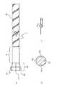
図7(a)ではロッド10の表面に溝70を形成してあり、ロッド10の外径を分散部本体1の内部にあけた孔の内径とほぼ同一としてある。従って、ロッド10を孔にはめ込むだけで、偏心することなく孔内にロッド10を配置することができる。また、ビスなどを用いる必要もない。この溝70がガス通路となる。
【0070】
なお、溝70はロッド10の長手方向中心軸と平行に複数本形成してもよいが、ロッド10の表面に螺旋状に形成してもよい。螺旋状の場合にはより均一性に優れた原料ガスを得ることができる。
【0071】
図7(b)はロッド10に突部を設けた例である。突部の最も大きな径を分散部本体1の内部にあけた孔の内径とほぼ同一としてある。突部と突部との間と孔の内面とで形成される空間がガス通路となる。
【0072】
なお、(a),(b)に示した例は、ロッド10の表面に加工を施してた例であるが、ロッドとして断面円形のものを用い、孔の方に凹部を設けてガス通路としてもよいことはいうまでもない。
【0073】
(実施例5)
図8に基づき実施例5を説明する。
【0074】
本例のMOCVD用気化器は、
内部に形成されたガス通路と、
ガス通路に加圧されたキャリアガス3を導入するためのガス導入口4と、
ガス通路に原料溶液5a,5bを供給するための手段と、
原料溶液5a、5bを含むキャリアガスを気化部22に送るためのガス出口7と、
を有する分散部8と、
一端がMOCVD装置の反応管に接続され、他端が前ガス出口7に接続された気化管20と、
気化管20を加熱するための加熱手段と、
を有し、
分散部8から送られてきた、原料溶液を含むキャリアガスを加熱して気化させるための気化部22と、
を有し、
分散部8は、円筒状中空部を有する分散部本体1と、円筒状中空部の内径より小さな外径を有するロッド10とを有し、
ロッド10の外周の気化器22側に1又は2以上の螺旋状の溝60を有し、
ロッド10は該円筒状中空部に挿入されている。
【0075】
高速のキャリアガス3が流れるガス通路に原料溶液5が供給されると、原料溶液は剪断・霧化される。すなわち、液体である原料溶液は、キャリアガスの高速流により剪断され、粒子化される。粒子化した原料溶液は粒子状態でキャリアガス中に分散しする。この点は、実施例1と同様である。
【0076】
なお、剪断・霧化を最適に行うためには、次ぎの条件が好ましい。
【0077】
原料溶液5の供給は、0.01〜1cc/minで行うことが好ましく、0.05〜0.5c/minで行うことがより好ましく、0.1〜0.3cc/minで行うことがさらに好ましい。複数の原料溶液(溶剤を含む)を同時に供給する場合には、そのトータル量である。
【0078】
また、キャリアガスは50〜300m/secの速度で供給することが好ましく、100〜200m/secの速度で供給することがより好ましい。
【0079】
本例では、ロッド10の外周には、螺旋状の溝60が形成してあり、かつ、分散部本体1とロッド10との間には隙間空間が存在するため、霧化状態となった原料溶液を含むキャリアガスはこの隙間空間を直進流として直進するとともに、螺旋状の溝60に沿って旋回流を形成する。
【0080】
このように、直進流と旋回流とが併存する状態において霧化した原料溶液はキャリアガス中に一様に分散することを本発明者は見いだしたのである。直進流と旋回流とが併存すると何故に一様の分散が得られるのかの理由は必ずしも明らかではないが、次のように考えられる。旋回流の存在により、流れに遠心力が働き、二次の流れが生じる。この二次の流れにより、原料及びキャリアガスの混合が促進される。すなわち、旋回流の遠心効果により流れに対して直角方向に2次的な派生流が生じ、これによって霧化した原料溶液がキャリアガス中により一様に分散するものと思われる。
【0081】
以下、本実施例をより詳細に説明する。
【0082】
本実施例では、一例として4種類の原料溶液5a,5b,5c,5d(5a,5b,5cは有機金属原料、5dはTHFなどの溶剤原料)をガス通路に供給するように構成されている。
【0083】
それぞれ霧化し、超微粒子状となった原料溶液を含むキャリアガス(「原料ガス」という)を混合するために、本例では、ロッド10の原料供給孔6に対応する部分の下流部分に螺旋状の溝のない部分を設けてある。この部分はプレミキシング部65となる。プレミキシング部65において、3種類の有機金属の原料ガスはある程度混合され、さらに、下流の螺旋構造の領域において完全な混合原料ガスとなる。均一な混合原料ガスを得るためには、このミキシング部65の長さは、5〜20mmが好ましく、8〜15mmがより好ましい。この範囲外の場合、3種類の有機金属の原料ガスのうち1種類のみの濃度が高い混合原料ガスが気化部22に送られてしまうことがある。
【0084】
本例では、ロッド10の上流側の端部66には、平行部67とテーパ部58とを設けてある。分散部本体1の円筒中空部にも平行部67とテーパー部58に対応した、ロッド10の平行部67の外径と同じ内径の平行部と、ロッド10のテーパーと同じテーパのテーパ部とを設けてある。従って、ロッド10を図面上左側から挿入すれば、ロッド10は分散部本体1の中空部内に保持される。
【0085】
本例では、実施例1の場合とは異なり、ロッド10にテーパを設けて保持しているため、3kgf/cm2よりも高圧のキャリアガスを用いてもロッド10の移動を防止することができる。すなわち、図8に示す保持技術を採用すれば、3kg/cm2以上の圧力でキャリアガスを流すことができる。その結果、より高速のキャリアガスの供給が可能となる。すなわち、50〜300mm/sの高速のキャリアガスの供給も可能となる。前記した他の実施例においてもこの保持技術を採用すれば同様である。
【0086】
なお、ロッド10の原料供給孔6に対応する部分には、図9(b)に示すように、キャリアガスの通路として溝67a,67b,67c,67dを形成しておく。各溝67a,67b,67c,67の深さとしては、0.005〜0.1mmが好ましい。0.005mm未満では溝の成形加工が困難となる。また、0.01〜0.05がより好ましい。この範囲とすることにより目詰まりなどの発生がなくなる。また、高速流が得られやすい。
【0087】
ロッド10の保持、ガス通路の形成については、実施例1における図1に示す構成その他の構成を採用してもかまわない。
【0088】
螺旋状の溝60は、図9(a)に示すように、1本でもよいが、図10に示すように複数本でもよい。また、螺旋状の溝を複数本形成する場合には、クロスさせてもよい。クロスさせた場合には、より均一に分散した原料ガスが得られる。
【0089】
螺旋状の溝60の寸法・形状には特に限定されず、図9(c)に示した寸法・形状が一例としてあげられる。
【0090】
なお、本例では、図8に示すとおり、ガス通路は、冷却水18により冷却している。
【0091】
また、本例では、分散部22の入口手前において、拡張部69を独立して設けてある。この拡張部69は実施例3において、述べた原料ガスの滞留を防止するための部分である。もちろん、拡張部69を独立して設ける必要はなく、図6に示したように一体化した構成としてもよい。
【0092】
拡張部69における拡張角度θとしては、5〜10度が好ましい。θがこの範囲内の場合、旋回流を壊すことなく原料ガスを分散部に供給することができる。また、θがこの範囲内の場合、拡大による流体抵抗が最小となり、また、デッドの存在が最小となり、デッドゾーンの存在による渦流の存在を最小にすることができる。なお、θとしては、6〜7度がより好ましい。なお、図6に示した実施例の場合においても好ましいθの範囲は同様である。
【0093】
(実施例6)
図8に示す装置を用い、次ぎなる条件で原料溶液及びキャリアガスの供給を行い、原料ガスにおける均一性を調べた。
【0094】
気化装置としては図8に示す装置を用いた。ただ、ロッドとしては、図9に示すロッドにおいて螺旋溝が形成されていないロッドを用いた。
【0096】
原料溶液を原料供給孔6から供給するとともにキャリアガスをその速度を各種変化させた。なお、原料供給孔からは、溝67aにはSr(DPM)2、溝67bにはBi(C6H5)3、溝67cにはTa(OC2H5)5、溝67dにはTHFをそれぞれ供給した。
【0097】
気化部における加熱を行わず、ガス出口7において原料ガスを採取し、採取した原料ガスにおける原料溶液の粒子径の測定を行った。
【0098】
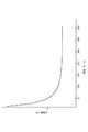
その結果を相対値(図12(a)に示す従来例に係る装置を用いた場合を1とする)として図11に示す。図11からわかるように、流速を50m/s以上とすることにより分散粒子径は小さくなり、100m/s以上とすることにより分散粒子径はさらに小さくなる。ただ、200m/s以上としても分散粒子径は飽和する。従って、100〜200m/sがより好ましい範囲である。
【0099】
(実施例7)
本例では、ロッドとして螺旋溝を形成したロッドを使用した。
【0100】
他の点は実施例6と同様とした。
【0101】
実施例6では、溝の延長部において、溝に供給された原料溶液の濃度が濃かった。すなわち、すなわち、溝67aの延長部では、Sr(DPM)2が、溝67bの延長部ではBi(C6H5)3が、溝67cの延長部ではTa(OC2H5)5がそれぞれ他の濃度が高かった。
【0102】
しかし、本例では、螺旋溝の端において得られた混合原料ガスはどの部分においても各有機金属原料が均一であった。
【0103】
【発明の効果】
本発明によれば、目詰まりなどを起こすことがなく長期使用が可能であり、かつ、反応部への安定的な原料供給が可能なMOCVD用気化器を提供することができる。
【0104】
本発明によれば、有機金属材料が均一分散された気化ガスを得ることができる。
【図面の簡単な説明】
【図1】実施例1に係るMOCVD用気化器の要部を示す断面図である。
【図2】実施例1に係るMOCVD用気化器の全体断面図である。
【図3】MOCVDのシステム図である。
【図4】リザーブタンクの正面図である。
【図5】実施例2に係るMOCVD用気化器の要部を示す断面図である。
【図6】実施例3に係るMOCVD用気化器の要部を示す断面図である。
【図7】(a),(b)ともに、実施例4に係り、MOCVD用気化器のガス通路の変形例を示す断面図である。
【図8】実施例5に係るMOCVD用気化器を示す断面図である。
【図9】実施例5に係るMOCVD用気化器に使用するロッドを示し、(a)は側面図、(b)はX−X断面図、(c)はY−Y断面図である。
【図10】図9(a)の変形例を示す側面図である。
【図11】実施例6における実験結果を示すグラフである。
【図12】(a),(b)ともに従来のMOCVD用気化器を示す断面図である。
【符号の説明】
1 分散部本体、
2 ガス通路、
3 キャリアガス、
4 ガス導入口、
5 原料溶液、
6 原料供給孔、
7 ガス出口、
8 分散部、
9a,9b,9c,9d ビス、
10 ロッド、
18 冷却するための手段(冷却水)、
20 気化管、
21 加熱手段(ヒータ)、
22 気化部、
23 接続部、
24 継手、
25 酸素導入手段(酸素供給口)、
29 原料供給入口、
30a,30b,30c,30d マスフローコントローラ、
31a,31b,31c,31d バルブ、
32a,32b,32c,32d リザーブタンク、
33 キャリアガスボンベ、
42 排気口、
40 バルブ、
44 反応管、
46 ガスパック、
51 テーパー、
70 溝。[0001]
[Industrial application fields]
The present invention relates to avaporizer .
[0002]
BACKGROUND OF THE INVENTION
A problem in the development of DRAMs is memory capacitance associated with miniaturization. From the standpoint of soft errors, the capacity is required to be the same as that of the previous generation. As a countermeasure, the cell structure up to 1M is a planar structure, but a solid structure called a stack structure or a trench structure has been introduced from 4M, and the capacitor area has been increased. As the dielectric film, a film in which a thermal oxide film and a CVD nitride film are laminated on poly-Si from a thermal oxide film of the substrate Si (this laminated film is generally referred to as an ON film) is employed. In the 16M DRAM, in order to further increase the area contributing to the capacity, the stack type has adopted a thick film type that uses the side surface, a fin type that also uses the back surface of the plate, and the like.
[0003]
However, in such a three-dimensional structure, an increase in the number of steps due to complicated processes and a decrease in yield due to an increase in level difference are regarded as problems, and realization after 256 Mbits is difficult. Therefore, as one way to further increase the integration without changing the structure of the current DRAM, a method of switching the capacitance dielectric to a ferroelectric having a high dielectric constant has been devised. As a dielectric thin film having a high dielectric constant, Ta2 O5 , Y2 O3 , HfO2, etc. were first noticed as a thin film of a high dielectric constant single metal paraelectric oxide. The relative dielectric constant of each of Ta2 O5 is 28, Y2 O3 is 16, HfO2 is about 24, and 4 to 7 times that of SiO2 .
[0004]
However, a three-dimensional capacitor structure is necessary for application after 256 MDRAM. Has a higher dielectric constant than these oxides as the material to be applied to a DRAM isexpected, (Ba x Sr 1-x )
[0005]
In general, the SrBi2 TaO9 ferroelectric thin film is formed by a practical and promising MOCVD (metal organic chemical vapor deposition) method.
[0006]
The raw materials for the ferroelectric thin film are generally three types of organometallic complexes Sr (DPM)2 , Bi (C6 H5 )3 and Ta (OC2 H5 )5 , each in a THF (tetrahydrofuran) solvent. Dissolved and used as a solution. Note that DPM is an abbreviation for dibibyromethane.
[0007]
The respective material properties are shown in Table 1.
[0008]
[Table 1]
The apparatus used for the MOCVD method is a reaction part for forming a film by subjecting a SrBi2 TaO9 thin film material to gas phase reaction and surface reaction, SrBi2 TaO9. It is composed of a supply section for supplying the thin film raw material and the oxidizing agent to the reaction section, and a recovery section for collecting the product in the reaction section.
[0010]
The supply unit is provided with a vaporizer for vaporizing the thin film raw material.
[0011]
Conventionally, a technique shown in FIG. 12 is known as a technique related to a vaporizer. Those shown in FIG. 12 (a) is what is called a metal filter expressions, gas and SrBi2 TaO9 existing around In this method, vaporization is performed by dropping a raw material solution heated to a predetermined temperature onto a metal filter used for the purpose of increasing the contact area with the ferroelectric thin film raw material solution.
[0012]
However, this technique has a problem that the metal filter is clogged after several vaporizations and cannot be used for a long time.
[0013]
FIG. 12B shows a technique for applying a pressure of 30 kgf / cm2 to the raw material solution to release the raw material solution from 10 μm pores and vaporize the raw material solution by expansion.
[0014]
However, this technique has a problem that the pores are clogged after several uses, and cannot be used for a long time.
[0015]
The raw material solution is a mixed solution of a plurality of organometallic complexes, for example, a mixed solution of Sr (DPM)2 / THF, Bi (C6 H5 )3 / THF, and Ta (OC2 H5 )5 / THF. Yes, when this mixed solution is vaporized by heating, the solvent with the highest vapor pressure (in this case, THF) is vaporized quickly, and the organometallic complex is deposited on the heated surface, so a stable feed to the reaction section The problem that cannot be done.
[0016]
Further, in MOCVD, in order to obtain a film having excellent uniformity, it is required to obtain a vaporized gas in which the raw material solution is uniformly dispersed. However, the above prior art cannot always meet such a request.
[0017]
[Problems to be solved by the invention]
An object of the present invention is to provide a vaporizer for MOCVD that can be used for a long time without causing clogging and the like and can stably supply a raw material to a reaction section.
[0018]
An object of this invention is to provide the vaporizer for MOCVD which can obtain the vaporization gas in which the raw material solution was disperse | distributed uniformly, and the vaporization method of a raw material solution.
[0019]
[Means for Solving the Problems]
The vaporizer of the present invention includes a gas passage formed therein,
A gas inlet for introducing a pressurized carrier gas into the gas passage;
Means for supplying a raw material solution to the gas passage;
A gas outlet for sending the carrier gas containing the raw material solution to the vaporization section;
Means for cooling the gas passage;
A dispersion part having
A vaporization unit for heating and vaporizing the carrier gas containing the raw material solution sent from the dispersion unit;
In a vaporizer having
And the gas passage, and the passage of the raw material solution for supplying a raw material solution into the gas passage, whereina cooling water passage forboth cooling and passage of the gas passageand the raw material solution, the inside of the dispersing portion It is formed integrally.
[0021]
The vaporization method of the present invention is a vaporization method for vaporizing a carrier gas in which a raw material solution is dispersed in a vaporization chamber, wherein the carrier gas in which the raw material solution flowing in the gas passage is dispersed is cooled.
[0022]
【Example】
Example 1
FIG. 1 shows a vaporizer for MOCVD according to the first embodiment.
[0023]
In this example, the gas passage 2 formed inside the dispersion part
A
Means (raw material supply holes) 6 for supplying the raw material solution 5 to the carrier gas passing through the gas passage 2;
A
A
A
A heating means (heater) 21 for heating the vaporizing
A vaporizing
Have
[0024]
Hereinafter, this embodiment will be described in more detail.
[0025]
In this example, a hole (cylindrical hollow part) having a diameter of 4.50 mm is formed in the dispersion part
[0026]
In addition, as a width | variety of a gas channel, 0.005-0.10 mm is preferable. If it is less than 0.005 mm, processing is difficult. If it exceeds 0.10 mm, it is necessary to use a high-pressure carrier gas in order to increase the carrier gas speed.
[0027]
A
[0028]
A
[0029]
At one end of the gas passage 2, a
[0030]
A
[0031]
In addition, by cooling the dispersion part, even if it is used for a long period of time, clogging with carbides in the gas passage (especially the gas outlet) does not occur.
[0032]
The
[0033]
The
[0034]
As the vaporizing
[0035]
The downstream end of the
[0036]
First, the start of the raw material solution to the vaporizer will be described.
[0037]
As shown in FIG. 3, the
[0038]
Each
[0039]
The details of the reserve tank are shown in FIG.
[0040]
The reserve tank is filled with the raw material solution, and each reserve tank (with an internal volume of 300 cc, 3 kgf / cm2 of carrier gas is supplied to SUS. The inside of the reserve tank is pressurized by the carrier gas. The raw material solution is pushed up in the tube on the side in contact with the solution and pumped to the liquid mass flow controller (manufactured by STEC, full scale flow rate 0.2 cc / min), where the flow rate is controlled and the raw material supply inlet of the vaporizer 29 to the raw
[0041]
It is transported to the reaction section by a carrier gas controlled at a constant flow rate by a mass flow controller (manufactured by STEC, full scale flow rate 2 L / min). At the same time, the mass flow controller (manufactured by STEC, with a full-scale flow rate of 2 L / min)-oxygen (oxidant) controlled to a constant flow rate is also transported to the reaction section.
[0042]
In the raw material solution, a liquid or solid organometallic complex is dissolved in THF as a solvent at room temperature. If left as it is, the organometallic complex is precipitated by evaporation of the THF solvent, and finally becomes solid. Become. Therefore, it is assumed that the inside of the pipe in contact with the undiluted solution causes the pipe to be blocked. Therefore, in order to suppress the blockage of the pipe, it is considered that the inside of the pipe and the vaporizer after the film forming operation should be washed with THF, and a washing line is provided. Cleaning is performed from the outlet side of the liquid mass flow controller to the vaporizer, and is washed away with THF after the operation is completed.
[0043]
The
[0044]
Meanwhile, a carrier gas was introduced from the gas inlet of the vaporizer. In addition, since the
[0045]
When the raw material solution is dripped from the raw
[0046]
The three kinds of raw material solutions controlled at a constant flow rate flow into the gas passage 2 from the raw
[0047]
The raw material solution released from the
[0048]
A vacuum pump (not shown) was connected from the
[0049]
Cooling water was passed through the vaporizer at about 400 cc / min. On the other hand, a carrier gas of 3 kgf / cm2 was flowed at 495 cc / min to sufficiently fill the
[0050]
The inside of the
[0051]
The inside of the reserve tank was pressurized with a carrier gas, and a predetermined liquid was flowed with a mass flow controller.
[0052]
Sr (DPM)2 , Bi (C6 H5 )3 , Ta (OC2 H5 )5 , and THF are 0.04 cc / min, 0.08 cc / min, 0.08 cc / min, and 0.2 cc / min, respectively. The flow rate was.
[0053]
After 20 minutes, the valve immediately before the
[0054]
Moreover, the adhesion amount of the carbide | carbonized_material in the outer surface by the side of the
[0055]
(Comparative Example 1)
In this example, an experiment similar to that of Example 1 was performed using the apparatus shown in FIG.
[0056]
In this example, the detected product and the product in the reaction formula examined based on the reaction theory were insufficient.
[0057]
Moreover, as a result of measuring the adhesion amount of the carbide on the outer surface of the
[0058]
(Example 2)
FIG. 5 shows a vaporizer for MOCVD according to the second embodiment.
[0059]
In the first embodiment, the
[0060]
The other points were the same as in Example 1.
[0061]
In this example, the detected product and the product in the reaction formula examined based on the reaction theory showed better agreement than in the case of Example 1.
[0062]
Moreover, as a result of measuring the adhesion amount of the carbide on the outer surface of the
[0063]
(Example 3)
FIG. 6 shows a vaporizer for MOCVD according to the third embodiment.
[0064]
In this example, the inside of the
[0065]
The other points were the same as in Example 1.
[0066]
In this example, the detected product and the product in the reaction formula examined based on the reaction theory showed better agreement than the case of Example 2.
[0067]
Moreover, as a result of measuring the adhesion amount of the carbide on the outer surface of the
[0068]
(Example 4)
FIG. 7 shows a modified embodiment of the gas passage.
[0069]
In FIG. 7A, a groove 70 is formed on the surface of the
[0070]
A plurality of grooves 70 may be formed in parallel with the longitudinal center axis of the
[0071]
FIG. 7B shows an example in which a protrusion is provided on the
[0072]
In addition, although the example shown to (a), (b) is an example which processed the surface of the
[0073]
(Example 5)
Example 5 will be described with reference to FIG.
[0074]
The vaporizer for MOCVD in this example is
A gas passage formed inside;
A
Means for supplying the
A
A
A
Heating means for heating the
Have
A
Have
The
Having one or more
The
[0075]
When the raw material solution 5 is supplied to the gas passage through which the high-
[0076]
In order to perform shearing and atomization optimally, the following conditions are preferable.
[0077]
The supply of the raw material solution 5 is preferably performed at 0.01 to 1 cc / min, more preferably performed at 0.05 to 0.5 c / min, and further preferably performed at 0.1 to 0.3 cc / min. preferable. When a plurality of raw material solutions (including a solvent) are supplied simultaneously, the total amount is used.
[0078]
The carrier gas is preferably supplied at a speed of 50 to 300 m / sec, and more preferably supplied at a speed of 100 to 200 m / sec.
[0079]
In this example, since the
[0080]
Thus, the present inventor has found that the atomized raw material solution is uniformly dispersed in the carrier gas in a state where the straight flow and the swirl flow coexist. The reason why uniform dispersion is obtained when the straight flow and the swirl flow coexist is not necessarily clear, but it is considered as follows. Due to the presence of the swirling flow, centrifugal force acts on the flow, and a secondary flow is generated. This secondary flow facilitates mixing of the raw material and the carrier gas. That is, it is considered that a secondary derivative flow is generated in a direction perpendicular to the flow due to the centrifugal effect of the swirl flow, whereby the atomized raw material solution is more uniformly dispersed in the carrier gas.
[0081]
Hereinafter, this embodiment will be described in more detail.
[0082]
In this embodiment, as an example, four kinds of
[0083]
In this example, in order to mix the carrier gas (hereinafter referred to as “raw material gas”) containing the raw material solution atomized into ultrafine particles, in this example, a spiral shape is formed in the downstream portion of the portion corresponding to the raw
[0084]
In this example, a
[0085]
In this example, unlike the case of Example 1, since the
[0086]
As shown in FIG. 9B,
[0087]
Regarding the holding of the
[0088]
The
[0089]
The dimensions and shape of the
[0090]
In this example, the gas passage is cooled by cooling
[0091]
Further, in this example, the
[0092]
The expansion angle θ in the
[0093]
(Example 6)
Using the apparatus shown in FIG. 8, the raw material solution and the carrier gas were supplied under the following conditions, and the uniformity in the raw material gas was examined.
[0094]
An apparatus shown in FIG. 8 was used as the vaporizer. However, as the rod, a rod in which no spiral groove was formed in the rod shown in FIG. 9 was used.
[0096]
The raw material solution was supplied from the raw
[0097]
The source gas was sampled at the
[0098]
The result is shown in FIG. 11 as a relative value (1 when the apparatus according to the conventional example shown in FIG. 12A is used). As can be seen from FIG. 11, the dispersed particle size is reduced by setting the flow rate to 50 m / s or more, and the dispersed particle size is further reduced by setting it to 100 m / s or more. However, the dispersed particle diameter is saturated even when the speed is 200 m / s or more. Therefore, 100 to 200 m / s is a more preferable range.
[0099]
(Example 7)
In this example, a rod formed with a spiral groove was used as the rod.
[0100]
The other points were the same as in Example 6.
[0101]
In Example 6, the concentration of the raw material solution supplied to the groove was high in the extended part of the groove. That is, Sr (DPM)2 is formed in the extended portion of the
[0102]
However, in this example, the mixed metal gas obtained at the end of the spiral groove was uniform in each organometallic raw material in any part.
[0103]
【The invention's effect】
ADVANTAGE OF THE INVENTION According to this invention, the vaporizer for MOCVD which can be used for a long term without causing clogging etc. and can supply a raw material stably to a reaction part can be provided.
[0104]
According to the present invention, a vaporized gas in which an organometallic material is uniformly dispersed can be obtained.
[Brief description of the drawings]
1 is a cross-sectional view showing a main part of a vaporizer for MOCVD according to Example 1. FIG.
2 is an overall cross-sectional view of a vaporizer for MOCVD according to Example 1. FIG.
FIG. 3 is a system diagram of MOCVD.
FIG. 4 is a front view of a reserve tank.
5 is a cross-sectional view showing a main part of a vaporizer for MOCVD according to Example 2. FIG.
6 is a cross-sectional view showing a main part of a vaporizer for MOCVD according to Example 3. FIG.
FIGS. 7A and 7B are cross-sectional views showing a modification of the gas passage of the vaporizer for MOCVD according to the fourth embodiment.
8 is a cross-sectional view showing a vaporizer for MOCVD according to Embodiment 5. FIG.
9A and 9B show rods used in a vaporizer for MOCVD according to Example 5, where FIG. 9A is a side view, FIG. 9B is an XX cross-sectional view, and FIG. 9C is a YY cross-sectional view.
FIG. 10 is a side view showing a modification of FIG.
11 is a graph showing experimental results in Example 6. FIG.
FIGS. 12A and 12B are sectional views showing a conventional vaporizer for MOCVD.
[Explanation of symbols]
1 Dispersing unit body,
2 gas passage,
3 Carrier gas,
4 Gas inlet,
5 Raw material solution,
6 Raw material supply hole,
7 Gas outlet,
8 Dispersion part,
9a, 9b, 9c, 9d screws,
10 rods,
18 Means for cooling (cooling water),
20 vaporizer tubes,
21 Heating means (heater),
22 Vaporization part,
23 connections,
24 joints,
25 oxygen introduction means (oxygen supply port),
29 Raw material supply inlet,
30a, 30b, 30c, 30d Mass flow controller,
31a, 31b, 31c, 31d valves,
32a, 32b, 32c, 32d reserve tank,
33 Carrier gas cylinder,
42 exhaust port,
40 valves,
44 reaction tubes,
46 Gas pack,
51 taper,
70 groove.
Claims (3)
Translated fromJapanese前記ガス通路に加圧されたキャリアガスを導入するためのガス導入口と、
前記ガス通路に原料溶液を供給するための手段と、
原料溶液を含むキャリアガスを気化部に送るためのガス出口と、
前記ガス通路を冷却するための手段と、
を有する分散部と、
前記分散部から送られてきた、原料溶液を含むキャリアガスを加熱して気化させるための気化部と、
を有する気化器において、
前記ガス通路と、前記ガス通路に原料溶液を供給するための原料溶液の通路と、前記ガス通路及び前記原料溶液の通路とをともに冷却するための冷却水通路と、が前記分散部の内部に一体
的に形成されていることを特徴とする気化器。A gas passage formed inside;
A gas inlet for introducing a pressurized carrier gas into the gas passage;
Means for supplying a raw material solution to the gas passage;
A gas outlet for sending the carrier gas containing the raw material solution to the vaporization section;
Means for cooling the gas passage;
A dispersion part having
A vaporization unit for heating and vaporizing the carrier gas containing the raw material solution sent from the dispersion unit;
In a vaporizer having
And the gas passage, and the passage of the raw material solution for supplying a raw material solution into the gas passage, whereina cooling water passage forboth cooling and passage of the gas passageand the raw materialsolution, the inside of the dispersing portion A vaporizer characterized by being integrally formed.
Priority Applications (1)
| Application Number | Priority Date | Filing Date | Title |
|---|---|---|---|
| JP2003189112AJP3987465B2 (en) | 2003-06-30 | 2003-06-30 | Vaporizer |
Applications Claiming Priority (1)
| Application Number | Priority Date | Filing Date | Title |
|---|---|---|---|
| JP2003189112AJP3987465B2 (en) | 2003-06-30 | 2003-06-30 | Vaporizer |
Related Parent Applications (1)
| Application Number | Title | Priority Date | Filing Date |
|---|---|---|---|
| JP01497099ADivisionJP3470055B2 (en) | 1999-01-22 | 1999-01-22 | MOCVD vaporizer and raw material solution vaporization method |
Related Child Applications (2)
| Application Number | Title | Priority Date | Filing Date |
|---|---|---|---|
| JP2005216010ADivisionJP4238239B2 (en) | 2005-07-26 | 2005-07-26 | Vaporization method |
| JP2007123985ADivisionJP2007258733A (en) | 2007-05-08 | 2007-05-08 | Vaporizing method and depositing method |
Publications (2)
| Publication Number | Publication Date |
|---|---|
| JP2004006928A JP2004006928A (en) | 2004-01-08 |
| JP3987465B2true JP3987465B2 (en) | 2007-10-10 |
Family
ID=30438411
Family Applications (1)
| Application Number | Title | Priority Date | Filing Date |
|---|---|---|---|
| JP2003189112AExpired - LifetimeJP3987465B2 (en) | 2003-06-30 | 2003-06-30 | Vaporizer |
Country Status (1)
| Country | Link |
|---|---|
| JP (1) | JP3987465B2 (en) |
- 2003
- 2003-06-30JPJP2003189112Apatent/JP3987465B2/ennot_activeExpired - Lifetime
Also Published As
| Publication number | Publication date |
|---|---|
| JP2004006928A (en) | 2004-01-08 |
Similar Documents
| Publication | Publication Date | Title |
|---|---|---|
| JP3470055B2 (en) | MOCVD vaporizer and raw material solution vaporization method | |
| JP4986163B2 (en) | MOCVD vaporizer and film deposition system | |
| EP1608005A1 (en) | Vaporizer, film forming apparatus including the same, method of vaporization and method of forming film | |
| EP1492160A1 (en) | Vaporizer, various devices using the same, and vaporizing method | |
| JP4391413B2 (en) | Vaporizer, disperser, film forming apparatus, and vaporization method | |
| JP2003273030A (en) | Method of causing cvd thin film for deposition | |
| JP5016416B2 (en) | Vaporizer and vaporization method | |
| JP4238239B2 (en) | Vaporization method | |
| JP3987465B2 (en) | Vaporizer | |
| JP5542103B2 (en) | Vaporizer | |
| JP5185726B2 (en) | Vaporizer, thin film forming apparatus, and MOCVD apparatus | |
| JP6014829B2 (en) | Vaporizer | |
| JP2015039001A (en) | Vaporizer | |
| JP2012094907A (en) | Vaporizer | |
| JP2007258733A (en) | Vaporizing method and depositing method | |
| JP2008205506A (en) | Vaporizer, and various apparatus and vaporizing method using the same |
Legal Events
| Date | Code | Title | Description |
|---|---|---|---|
| A131 | Notification of reasons for refusal | Free format text:JAPANESE INTERMEDIATE CODE: A131 Effective date:20060726 | |
| A521 | Written amendment | Free format text:JAPANESE INTERMEDIATE CODE: A523 Effective date:20060925 | |
| A02 | Decision of refusal | Free format text:JAPANESE INTERMEDIATE CODE: A02 Effective date:20061025 | |
| A521 | Written amendment | Free format text:JAPANESE INTERMEDIATE CODE: A523 Effective date:20061225 | |
| A911 | Transfer to examiner for re-examination before appeal (zenchi) | Free format text:JAPANESE INTERMEDIATE CODE: A911 Effective date:20070307 | |
| A131 | Notification of reasons for refusal | Free format text:JAPANESE INTERMEDIATE CODE: A131 Effective date:20070502 | |
| A521 | Written amendment | Free format text:JAPANESE INTERMEDIATE CODE: A523 Effective date:20070508 | |
| TRDD | Decision of grant or rejection written | ||
| A01 | Written decision to grant a patent or to grant a registration (utility model) | Free format text:JAPANESE INTERMEDIATE CODE: A01 Effective date:20070704 | |
| A61 | First payment of annual fees (during grant procedure) | Free format text:JAPANESE INTERMEDIATE CODE: A61 Effective date:20070712 | |
| R150 | Certificate of patent or registration of utility model | Free format text:JAPANESE INTERMEDIATE CODE: R150 | |
| FPAY | Renewal fee payment (event date is renewal date of database) | Free format text:PAYMENT UNTIL: 20100720 Year of fee payment:3 | |
| FPAY | Renewal fee payment (event date is renewal date of database) | Free format text:PAYMENT UNTIL: 20110720 Year of fee payment:4 | |
| FPAY | Renewal fee payment (event date is renewal date of database) | Free format text:PAYMENT UNTIL: 20120720 Year of fee payment:5 | |
| FPAY | Renewal fee payment (event date is renewal date of database) | Free format text:PAYMENT UNTIL: 20130720 Year of fee payment:6 | |
| R250 | Receipt of annual fees | Free format text:JAPANESE INTERMEDIATE CODE: R250 | |
| R250 | Receipt of annual fees | Free format text:JAPANESE INTERMEDIATE CODE: R250 | |
| R250 | Receipt of annual fees | Free format text:JAPANESE INTERMEDIATE CODE: R250 | |
| R250 | Receipt of annual fees | Free format text:JAPANESE INTERMEDIATE CODE: R250 | |
| R250 | Receipt of annual fees | Free format text:JAPANESE INTERMEDIATE CODE: R250 | |
| R250 | Receipt of annual fees | Free format text:JAPANESE INTERMEDIATE CODE: R250 | |
| EXPY | Cancellation because of completion of term |