JP3985456B2 - Mobile communication system, mobile terminal, base station controller, and packet data service node - Google Patents
Mobile communication system, mobile terminal, base station controller, and packet data service nodeDownload PDFInfo
- Publication number
- JP3985456B2 JP3985456B2JP2001013961AJP2001013961AJP3985456B2JP 3985456 B2JP3985456 B2JP 3985456B2JP 2001013961 AJP2001013961 AJP 2001013961AJP 2001013961 AJP2001013961 AJP 2001013961AJP 3985456 B2JP3985456 B2JP 3985456B2
- Authority
- JP
- Japan
- Prior art keywords
- mobile terminal
- base station
- radio channel
- timer
- packet
- Prior art date
- Legal status (The legal status is an assumption and is not a legal conclusion. Google has not performed a legal analysis and makes no representation as to the accuracy of the status listed.)
- Expired - Fee Related
Links
Images


Landscapes
- Small-Scale Networks (AREA)
- Mobile Radio Communication Systems (AREA)
Description
Translated fromJapanese【0001】
【発明の属する技術分野】
本発明は、移動体通信システムに関し、特に通信品質保証機能を備えた移動体通信システム、移動端末、基地局制御装置及びパケットデータサービスノードに関する。
【0002】
【従来の技術】
従来例えば次世代移動体通信の標準化団体である3rd Generation Partnership Project 2 (3GPP2)による規格であるStage 3 description of Ax interface rev.1 (3gpp2-ACO-19990927-0)に記載されているように、移動体通信システムにおいては無線チャネルを有効に利用するために、パケット交換方式を用いて複数の端末間で無線チャネルを共有する方法が知られている。この方式では、各移動体端末は信号の送信または受信要求が発生した場合には他の端末と共有で割り当てられている無線チャネルを使用してパケットの形で信号を送受信し、送受信要求がない場合には無線チャネルを開放して他の移動体端末が無線チャネルを使用できるようにしている。しかしある一定時間パケットの送受信が行なわれなかった移動体端末に対しては、無線チャネルの割り当て自体が解除される。
【0003】
【発明が解決しようとする課題】
上述した移動体通信システムでは、無線チャネルの割り当てが解除されてしまった移動体端末に再び送受信要求が発生した場合、その移動体端末に対して無線チャネルを割り当てることから始めなければならないが、割り当て可能な空き無線チャネルを確保できない可能性がある。また移動体通信システムにおいては、移動体端末のセル間の移動に伴って、移動先のセルを制御している無線基地局から無線チャネルの割り当てを受ける必要があるが、この場合にも割り当て可能な空き無線チャネルを確保できない可能性がある。これは、電子商取引等高度な信頼性を要求される通信を行う場合に通信品質保証上重要な課題となる。
【0004】
本発明の目的は、無線チャネルの優先的な使用を必要とする場合に、パケット送受信の間隔に関わらず無線チャネルの割り当てを受け続け、また無線チャネルの割り当て要求時に際しても優先的に無線チャネルの割り当てを受けられる手段を持った移動端末を提供することである。
【0005】
本発明の他の目的は、無線チャネルの優先使用要求を発した移動体端末に対して、パケット送受信の間隔に関わらず無線チャネルを割り当て続け、また優先使用要求を発している移動体端末が無線チャネルの割り当てを要求した場合には優先的に無線チャネルを割り当てる手段を持った基地局制御装置を提供することである。
【0006】
本発明の他の目的は、無線チャネルの優先使用要求を発した移動体端末に対して、無線チャネルを優先的に使用させる手段を持ったパケットデータサービスノードを提供することである。
【0007】
本発明の他の目的は、無線チャネルの優先使用要求を発した移動体端末にはパケット送受信の間隔に関わらず無線チャネルを割り当て続け、また無線チャネルの優先使用要求を発している移動体端末が無線チャネルの割り当てを要求した場合には優先的に無線チャネルを割り当てることができる移動体通信システムを提供することである。
【0008】
【課題を解決するための手段】
上記目的を達成するために、本発明においては、無線チャネルの優先的な使用を要求する移動体端末は、無線基地局に対して周期的に優先要求を送信し、優先要求を受信した無線基地局は優先要求端末に対して周期的に応答を送信するようにしたことを特徴する。これにより優先使用要求を発している移動体端末と無線基地局との間には周期的な送受信が行なわれることになるため、送受信の周期がチャネル割り当ての解除までの時間より短ければ、移動体端末は無線チャネルの割り当てを受け続けることができる。
【0009】
更に、本発明においては、無線基地局を制御している基地局制御装置が、無線チャネルを優先的に使用している優先端末と、優先端末以外の非優先端末とを分けて管理し、非優先端末については無線基地局との間での最後の信号の送信または受信時からの経過時間(無線チャネル未使用時間)順に管理する手段を有している。従って、無線チャネルの優先使用要求を発している移動体端末が無線チャネルの割り当てを要求し、無線基地局に割り当て可能な空き無線チャネルが存在しなかった場合には、基地局制御装置は無線基地局に対して、非優先端末の内無線チャネル未使用時間が長い移動体端末から順に無線チャネルの割り当てを解除し、その無線チャネルを優先使用要求端末に割り当てるよう制御することが可能となる。
【0010】
【発明の実施の形態】
図1は本発明を適応する移動体データ通信システム101の一構成例を示している。本システムは、複数の移動体端末(以下MSとする)102を収容し、セル103(103A〜103F)というサービスエリア内に存在するMS102と信号の送受信を行う基地局(以下BSとする)104(104A〜104F)と、複数の基地局104を統合管理する基地局制御装置(以下BSCとする)105(105A〜105D)からなる無線アクセスネットワーク(以下RANとする)110と、無線アクセスネットワーク110と接続し、IPパケットルーティング機能を持つパケットデータサービスノード(以下PDSNとする)106(106A、106B)と、PDSN106間の端末の移動を実現するホームエージェント(以下HAとする)108と、外部ネットワークであるインターネットあるいは企業内LANと接続するゲートウェイルータ107(107B,107C)及び前記ルータとPDSN106間を接続するルータ107Aから構成するパケットコアネットワーク109より構成する。
【0011】
図2は、MS102とPDSN106間のコネクションのマッピング例を示す図である。MS102とBSC105間には無線チャネル203が、BSC105とPDSN106間にはリンクレイヤコネクション202が設定され、両コネクションにPPPコネクション201がマッピングされる構成である。移動体端末の移動により生じる無線チャネル203とリンクレイヤコネクション202のマッピング変更をBSC105で管理することにより、MS102のBS104間の移動を実現し、PPPコネクション201とリンクレイヤコネクション202のマッピング変更をPDSN106で管理することにより、MS102のBSC105間の移動を実現する。
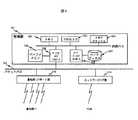
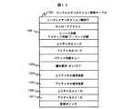
図4は本発明を適用したMS102の構成の一例を示している。MS102は、アンテナ404、アンテナを介してデータを送受信するための符号、複号処理を行う送受信処理部403、ユーザインターフェース部401、ユーザインタフェース部の制御及びデータのプロトコル処理を行い送受信処理部とのインタフェースを持つコントロール部402、及びバッテリー415から構成する。ユーザインタフェース部401は、表示部407、スイッチ部416、スピーカ413、マイク414から構成し、スイッチ部416は、電源のオンオフを行う電源スイッチ408、数字及び文字入力を行うダイヤルキー409、発信実行、着信時の通話開始及びデータサービス開始を行うセレクトキー410、表示部のスクロールを行うスクロールキー411、及びユーザからの入力やユーザが利用しているサービスに応じてなされるコントロール部402からの指示に応じて通信品質保証を要求するQoSキー412を備えている。コントロール部402は、スイッチ部416から入力された要求に応じたサービスを開始し、サービスに関連する送受信トラヒックに対するプロトコル処理、表示部の制御を実行するCPU418、それらのプログラムを格納するメモリであるROM406、プロトコル処理に必要なステート情報、及び無線リソース状態を記憶するメモリであるRAM405から構成する。417はバスであり、401、402、403を互いに接続し、データ、プログラムのやり取りを行う。
【0012】
図5はBSC105の一構成例を示している。BSC105は、管理部501、基地局I/Fポート部510、及びネットワークI/F部511から構成し、各部はパケットバス509を介して接続する。管理部501は、各BS104の無線リソース管理、リンクレイヤコネクション202と無線チャネル203間の変換を実行するプロセッサ503、それらのプログラムを格納するメモリ502、無線チャネルの識別子である無線チャネルコード管理テーブル及びMS対応に備える無線チャネルコードと無線リソース状態を管理するテーブル等を配置するメモリキャッシュ504、転送するデータを一時的に格納するバッファメモリ505、バッファメモリコントローラ506、ハードディスク507及びハードディスクコントローラ508から構成する。BS104とは基地局I/Fポート部510を介して接続する構成とし、本実施例では、4つのBS104に接続できる構成を示している。PDSN106とはネットワークI/F部511を介して接続する。
【0013】
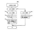
図6はPDSNの一構成例を示している。PDSNは管理部601、一つ以上のルーティング部602から構成し、各部はパケットバス603を介して接続する。管理部601は、パケットルーティングテーブルを作成するプログラムを格納するメモリ605Aと、そのプログラムを実行するプロセッサ610A、パケットルーティングテーブル及びMSに関する情報を配置するメモリキャッシュ611A、パケットを格納するバッファメモリ606A、ルーティング部602のバッファメモリ606Bとの間のパケットのDMA転送機能及びパケットバス制御機能からなるバッファメモリコントローラ607A、ハードディスクコントローラ608及びハードディスク609から構成される。プロセッサ610Aが作成するパケットルーティングテーブルは、移動体データ通信システム101に存在するMS102の位置情報を収集しHA108へ通知するといったMobile IPの処理やMS102とのPPPコネクション201設定、BSC105とのリンクレイヤコネクション202設定、Mobile IPのIPトンネリングとPPPコネクション201の対応付け、及びPPPコネクション201とリンクレイヤコネクション202対応付けを管理する。ルーティング部602は、管理部が作成したパケットルーティングテーブルをもとにHA108とBSC105間のパケット転送処理を実行するプロセッサ610B、メモリ605B、バッファメモリ606B、バッファメモリコントローラ607B、管理部で作成したパケットルーティングテーブル等を配置するメモリキャッシュ611B、他ルータ107等を接続するポート制御部612、及び内部バスを持つものである。本図では一つのポート制御部612にて4ポートをサポートする構成とし、本実施例では本ポートを介して、一つ以上のルータ107及び一つ以上のBSC105と接続する。
【0014】
図7は、パケット交換における無線リソース状態の遷移図である。状態は、MS102が移動体データ通信システム101に接続していない(電源が入っていない、データ送受信ができない)状態であるヌル状態701、MS102が移動体データ通信システム101に接続し、かつ無線チャネルの割り当てを受けている状態であるアクティブ状態702、MS102が移動体データ通信システム101に接続しているが、無線チャネルの割り当てを受けていない状態であるドーマント状態703の三状態から構成する。アクティブ状態702であるMS102において一定時間信号の送信または受信が行われない場合、無線チャネルの割り当ては解除されドーマント状態703になる。本移動体データ通信システムにおいては、図7に示すアクティブ状態702のMSのみがBS104とのパケット送受信を行うことが可能であり、ヌル状態701またはドーマント状態703のMSはパケットの送受信を行う場合にはランダムアクセスチャネルまたは制御チャネルを利用してBSC105に対して無線チャネルの割り当てを要求し、BSC105の制御により無線チャネルの割り当てを受けてアクティブ状態702へ遷移する必要がある。アクティブ状態へ遷移することに失敗したMS102は一定時間が経過した後に再度無線チャネルの割り当てを要求しても良い。
【0015】
図7に示した状態遷移を実現するために、BSC105は管理部501に各MS102毎に状態遷移タイマ901Bを持ち、MS102との間で信号を送信または受信する毎にそのMSに対応した状態遷移タイマ901Bをリスタートさせる。この様子を図9に示す。本タイマがタイムアウトした場合、BSC105は対応するMS102に対する無線チャネルの割り当てを解除し、MS102はアクティブ状態702からドーマント状態703に遷移する。移動体データ通信システム101では、MS102がリアルタイムアプリケーションや電子商取引の様に高度な信頼性が要求される通信を行っている際にも、一定時間信号の送受信が行なわれないとリソース状態がドーマント状態703に遷移し、無線チャネルの割り当てが解除される。また、信号の送受信を再開する際に必ず割り当て可能な無線チャネルが確保出来るとは限らないため、サービス利用が出来なくなる場合がある。
【0016】
このような課題を解決する為本発明では、無線チャネルの優先的な使用を必要とする場合に、ユーザがMS102が有するQoSキー412を押すことにより、またはユーザが利用しているサービスに応じてMS102のコントロール部402が無線チャネルの優先的な使用を指示することによって、アクティブ状態702からドーマント状態703への状態遷移を回避し、無線チャネルの割り当てを継続的に受けることを可能にしている。
【0017】
図8はBS104から割当てられている無線チャネルの継続的な割当てを実現するためにMS102で行なわれる優先要求の入力処理のフローである。ユーザがQoSキー412を入力した場合、またはユーザが利用するサービスやアプリケーションに応じてコントロール部402が優先要求を指示した場合、MS102はQoSキー状態をオン状態とし(801)、BSC105による無線チャネルの割り当て解除を回避する為に、一定周期毎にPPPキープアライブパケットを送信する(802)。
【0018】
図18は、PPPキープアアライブパケットの構成例を示す。PPPキープアライブパケット1800は、MS102の識別子を格納するフィールド1801と、PPPキープアライブパケットのパケット種別情報を格納するフィールド1802を有する。通信方式としてCDMAが採用されている場合には、PPPキープアライブパケットに使用されている拡散符号からMS102を識別することができるので、MS102の識別子を格納するフィールド1801はなくてもよい。
【0019】
その後、MS102がコントロール部402に有するPPPキープアライブパケットの送信周期を計測する為のPPPコネクションタイマ902の値を、MS102がコントロール部402に有する状態遷移タイマ901Aの値より小さい値に設定する(803)。状態遷移タイマ901Aは、BSC105との間での最後の信号の送信時または受信時から、MS102に対する無線チャネルの割り当てが解除されるまでの期間を計測するタイマである。従って、結果的に状態遷移タイマ901AはBSC105がMS102毎に有する状態遷移タイマ901Bと同様の計測を行うことになる。
【0020】
この場合の、状態遷移タイマ901A、901B、PPPコネクションタイマ902とQoSキー状態の関係例を図9に示す。QoSキー412がオン状態の場合、PPPコネクションタイマ値は状態遷移タイマ901A値より小さく設定する為、状態遷移タイマ901BがタイムアウトすることによってMS102への無線チャネルの割り当てが解除されMS102がアクティブ状態702からドーマント状態703へ移行する前に、PPPコネクションタイマ902がタイムアウトする。MS102はPPPコネクションタイマ902がタイムアウトしかつ状態遷移タイマ901Aがタイムアウトしていない場合に、PPPキープアライブパケットを送信する。BSC105はPPPキープアライブパケットを受信した場合、MS102に対して応答パケットを送信する。
【0021】
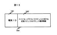
図19は応答パケット1900の構成例を示す。応答パケット1900は、応答パケットの宛先であるMS102の識別子を格納するフィールド1901と、応答パケットのパケット種別情報を格納するフィールド1902を有する。通信方式としてCDMAが採用されている場合には、応答パケットに使用されている拡散符号からMS102を識別することができるので、MS102の識別子を格納するフィールド1901はなくてもよい。
【0022】
MS102はPPPキープアライブパケットの送信、またはBSC105からの応答パケットの受信によって状態遷移タイマ901Aをリスタートさせ、BSC105はMS102からのPPPキープアライブパケットの受信、またはMS102への応答パケットの送信によって状態遷移タイマ901Bをリスタートさせるため、無線チャネルの割り当て解除を回避することができる。
【0023】
サービス利用が終了した時点でユーザが再度QoSキー412を入力することにより、またはコントロール部402がサービス利用の終了に応じて無線チャネルの優先利用解除の指示をすることにより、QoSキー状態はオフとなる(804)。この場合、PPPコネクションタイマ902の値を通常値(状態遷移タイマ901Aより長いタイマ値)に設定する(805)。一定期間パケットの送受信がなければ、PPPコネクションタイマ902より先に状態遷移タイマ901Bがタイムアウトし、無線チャネルの割り当てが解除されドーマント状態703への遷移が起こる。またドーマント状態への遷移後PPPコネクションタイマ902がタイムアウトした場合にも、状態遷移タイマ901Aがタイムアウトしている場合にはMS102はPPPキープアライブパケットを送信しない。
【0024】
MS102はヌル状態あるいはドーマント状態からアクティブ状態へ移行する場合、またはMS102がセル間を移動した場合に、ランダムアクセスチャネル、あるいは制御チャネルを使用して無線チャネルの割り当てをBSC105に要求する。無線チャネルの割り当て要求パケットの構成例を図17に示す。1701はチャネル割り当てを要求するMS102の番号であり、1702はMSがチャネル割り当てを要求しているセルに対してサービスを行っている BS104の番号である。1703は、BS104から送信している止まり木チャネル(以下BCCHと称す)におけるBCCH送信電力値であり、1704は上りチャネルの干渉量である。1705は、MS102で計測したBCCHの受信電力であり、1706はBCCHの受信SIRである。1707は下りチャネルの通信速度の要求値であり、1708は上りチャネルの通信速度の要求値である。尚、MS102がセル間を移動した場合には、移動したMS102が利用しているサービスや使用しているチャネルの通信速度をBSC105が把握しているので、図17に示した情報の一部または全てを省き、MS102のセル間の移動に伴う無線チャネルの割当て要求をBSC105が自動的に把握することも可能である。
【0025】
例えば電波産業界(ARIB)によるCDMA方式携帯自動車電話システム標準規格であるARIB STD−T53では、BSCは各セル毎の通信品質として希望波レベル(RSSI)、干渉波レベル(ISSI)、希望波対干渉信号電力比(SIR)、フレームエラーレート(FER)の情報をBS104から定期的に収集し、メモリ502に記憶する。そこでBSC105は、MS102から無線チャネルの割り当て要求を受信した場合に、メモリ502に記憶している該当セルの情報と、無線チャネル割当要求パケットに含まれている要求通信速度、BCCHのSIR、上りチャネルの干渉量等の情報から、割り当て要求MSに無線チャネルを割り当てた場合に通信品質がどの程度まで劣化するか、例えば割り当て要求を送信したMSに無線チャネルを割り当てた場合の干渉波レベルをプロセッサ503により予測し、予測結果の干渉波レベルが予め設定されている許容値を満たしているかどうかを基準に無線チャネルを割り当てるかどうかを判断する。また干渉波レベルの代わりに、BSCは無線チャネルの割当て要求MSに無線チャネルを割当てた場合に、割当てを行ったBSにおいてアクティブ状態にある全MSの通信速度合計が、予め設定されている閾値を超えないかどうかを基準に無線チャネルを割り当てるかどうか判断しても良い。
【0026】
無線チャネルの優先的な使用を必要とするユーザが、無線チャネルの割り当て要求時に優先的な割り当てを受け、割当てられた無線チャネルを継続して使用するためのMS102における優先要求の入力処理を示すフローを図10に示す。ユーザがQoSキー412の入力を行った場合、またはユーザが利用するサービスに応じてコントロール部402が無線チャネルの優先使用要求を指示した場合、MS102は接続しているPDSN106宛てにQoS要求を送付する(1001)。
【0027】
図20はQoS要求パケットの構成例を示す。QoS要求パケット2000は、MS102の識別子を格納するフィールド2001と、QoS要求パケットのパケット種別情報を格納するフィールド2002を有する。通信方式としてCDMAが採用されている場合には、QoS要求パケットに使用されている拡散符号からMS102を識別することができるので、MS102の識別子を格納するフィールド2001はなくてもよい。
【0028】
QoS要求を受信し、MS102への優先制御許可の要否を判断したPDSN106からのリプライにより(1002)、優先制御が許可された場合(1003)、QoSキー状態をオンとし(1004)、無線チャネルの割当てをBSC105に要求する(1005)。MS102のセル間の移動に伴う無線チャネルの割当て要求の場合には、BSC105が自動的にMS102の無線チャネル割当て要求を把握していてもよい。BSC105より無線チャネルの割当てが受けられなかった場合には、一定時間が経過した後に再び無線チャネルの割当てを要求してもよい。BSC105より無線チャネルの割当てを受けた場合には、図8にて説明したように、MS102はPPPコネクション201保持する為に、一定周期毎にPPPキープアライブパケットを送信する(1006)。更に、PPPコネクションタイマ902値を状態遷移タイマ901A値より小さい値を設定する(1007)。この設定により、MS102はアクティブ状態702を保持する事ができる。例えばMS102の加入契約によりPDSN106から優先制御が許可されない場合、MSの表示部にQoS機能使用不可を表示する(1008)。この場合MS102は優先制御されない通常のMSとしてBSC105に無線チャネルの割当てを要求する(1009)。無線チャネルの割当てが受けられなかった場合には、一定時間が経過した後に再び無線チャネルの割当てを要求してもよい。無線チャネルの割当てを受けた場合、MS102は優先制御を受けることはできないため、PPPキープアライブパケットの送信は行わない。
【0029】
ユーザがサービス利用が終了した時点で再度QoSキー412を入力することにより、またはコントロール部402がサービス利用の終了に応じて無線チャネルの優先利用解除の指示をすることにより、QoSキー状態はオフとなる(804)。この場合、PPPコネクションタイマ902値を通常値(状態遷移タイマ901Aより長いタイマ値)に設定する(805)。
【0030】
MS102からのQoS要求を受信したPDSN106の処理を示すフローが図11である。本処理は、PDSN106の管理部601のプロセッサ610Aにて実行する。QoS要求受信した後、要求MSに対応するMS情報テーブル1201を検索する(1101)。図12にMS情報テーブル1201の一構成例を示す。MS情報テーブルはPDSN106のメモリキャッシュ611Aに配置されている。MS情報テーブル1201は、加入者情報から入手した移動体端末固有識別子、移動体網に接続後に割付けられるテンパラリーな移動端末仮識別子、認証・秘匿情報、MSが使用しているIPアドレス、位置情報、ホームネットワーク識別子、ホームエージェントアドレス及び優先処理契約の有無1203や契約転送スループット1204等の契約しているQoSサービス情報1202から構成する。MS情報テーブル検索後、QoSサービス情報1202をもとに優先処理契約がなされているかどうかを判断し(1102)、優先契約がなされていない場合、優先制御が提供できない事をMS102に通知する(1106)。優先制御契約がなされている場合、MS102が接続しているBSC105に対して、MS優先指示を通知し(1103)、そのリプライを受けた後(1104)、MSに対して優先制御提供可能である事を通知する(1105)。
【0031】
BSC105は、MS102に割り当てられた無線チャネル203とリンクレイヤコネクション202のマッピングを管理するリンクレイヤコネクション管理テーブル1301をMS対応に備えている。図13はリンクレイヤコネクション管理テーブル1301の一構成例である。リンクレイヤコネクション管理テーブル1301は、BSC105のメモリキャッシュ504に配置されており、リンクレイヤコネクション識別子、MSのIPアドレス、リソース状態1302、無線チャネル303を識別する上りチャネルコード、下りチャネルコード、パケット待避キュー、優先要求の有無1303、上りチャネル通信速度1304、下りチャネル通信速度1305、上りチャネルSIR1306、下りチャネルSIR1307及び管理ポインタから構成する。BSC105は更に、BS104が管理するセル103毎に、使用している無線チャネルコードを管理し優先制御を実現するためのチャネルコード管理テーブル1401を備えている。チャネルコード管理テーブル1401の一構成例を図14に示す。チャネルコード管理テーブル1401はBSC105のメモリキャッシュ504に配置されており、優先契約をしており、かつ優先処理中のMS102のレイヤリンクコネクション管理テーブル1301を登録する優先MS管理キュー1402、優先契約はしているがQoS要求のないMS102及び優先契約をしていないMS102のリンクレイヤコネクション管理テーブル1301を登録する通常MS管理キュー1403から構成される。MS102が無線チャネルを介して信号を送信または受信する毎に、そのMS102に対応するリンクレイヤコネクション管理テーブル1301は、BSC105の管理部501に配置されたプロセッサ503によって、管理キュー1402または1403の先頭に登録し直される。従って管理キュー1402,1403の先頭から順に、最後の信号の送信または受信時点からの経過時間が短いMS102のリンクレイヤコネクション管理テーブル1301が登録されていることになる。
【0032】
ここで、例えば既にアクティブ状態にあったMS102がQoS要求をPDSN106に送信し、PDSN106がBSC105に対してMS102への優先指示を通知した場合を想定する。図15はこの時に、PDSN106からのMS優先指示を受付けたBSC105における処理フローを示す図である。本処理は、BSC105の管理部501に配置するプロセッサ503で実行する処理である。BSC105は優先処理を行うMS102に対応するリンクレイヤコネクション管理テーブル1301を検索し(1501)、該当するテーブルの優先要求1303をオンにする(1502)。本テーブルをチャネルコード管理テーブル1401の通常MS管理キュー1403から優先MS管理キュー1402の先頭に登録し直し(1503)、優先指示に対する処理終了をPDSN106に通知する(1504)。
【0033】
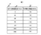
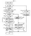
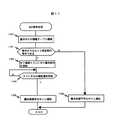
次に、アクティブ状態702にあって、既にBSC105から優先処理を受けている優先要求MS102が、BS104間(セル103間)を移動した場合、またはヌル状態701あるいはドーマント状態703にあるMS102がQoS要求を送信し、更にチャネル割り当て要求を送信してアクティブ状態702に遷移する場合を想定する。図16はBS104において優先要求MS102に対し無線チャネルを優先的に割り当てるための制御処理を示すフローである。本処理は、BSC105の管理部501に配置するプロセッサ503で実行する。MS102がセル間を移動した場合には(1601)移動したMS102のリンクレイヤコネクション管理テーブル1301を旧BS103に対応したチャネルコード管理テーブル1401から外す(1602)。図13に示したリンクレイヤコネクション管理テーブルを利用して、無線チャネルの割り当て要求先である新BS103でアクティブ状態にある全MSの通信速度合計を上りチャネル、下りチャネルのそれぞれで計算し、優先要求MS102から受信した無線チャネル割当て要求パケットまたはBSC105が予め把握していたセル間の移動前にMS102が使用していたチャネルの通信速度をもとに、優先要求MS102が要求している通信速度を割り当てても閾値を越えないかを判断する(1603)。上りチャネル、下りチャネルそれぞれについて優先要求MS102に無線チャネルを割り当てた場合の通信速度合計と干渉波レベルをプロセッサ503により計算し、計算結果が図3に示す閾値を越えないかどうかを判断してもよい。閾値を越えていなければ無線チャネルチをMS102に割付け(1604)、新BS102に対応したチャネルコード管理テーブル1401の優先MS管理キュー1402の先頭にリンクレイヤコネクション管理テーブル1301を登録する(1605)。閾値を越えていた場合、移動先BS103のチャネルコード管理テーブル1401の通常MS管理キュー1403に登録されているリンクレイヤコネクション管理テーブル1301があるかどうかを判断する(1606)。通常MS管理キュー1403に登録されているリンクレイヤコネクション管理テーブル1301がなければ、無線チャネルは全て優先MSによって使用されているため、優先要求MSに無線チャネルを割り当てることはできない(1612)。通常MS管理キュー1403に登録されているリンクレイヤコネクション管理テーブル1301があれば、通常MS管理キュー1403にリンクレイヤコネクション管理テーブルが登録されている通常MS102に対する無線チャネルの割当てを全て解除し、優先要求MSに無線チャネルを割当てた場合の通信速度合計が閾値を超えないかを判断する(1607)。全通常MSに対する無線チャネルの割り当てを解除し、優先要求MSに無線チャネルを割り当てた場合の干渉電力と通信速度の合計を計算して、干渉電力が図3に示す閾値を越えていないかどうかを判断してもよい。通信速度の合計または干渉電力が閾値を越えてしまう場合には、優先要求MSに無線チャネルを割り当てることはできない(1612)。それ以外の場合には、通常MS管理キュー1403の最後にリンクレイヤコネクション管理テーブル1301が登録されている通常MSから順に、優先要求MSに無線チャネルを割り当てた時の全MS通信速度合計または干渉レベルが閾値以下になるまで、無線チャネルの割当てを解除し、強制的にドーマント状態へ遷移させる(1608,1609,1610)。優先要求MSに通常MSから割り当てを解除した無線チャネルを割り当て(1611)、無線チャネルを割り当てたBSに対応したチャネルコード管理テーブルの優先MS管理キュー1402の先頭に優先要求MSのリンクレイヤコネクション管理テーブル1301を登録する(1605)。
【0034】
以上の構成により、ユーザあるいは利用しているアプリケーションが通信品質保証を必要としている場合に、移動体端末が無線チャネルの優先使用要求パケット(PPPキープアライブパケット)を周期的に送信することによって、アクティブ状態からドーマント状態への遷移タイミングを計測している状態遷移タイマのタイムアウトを回避し、優先要求移動体端末は無線チャネルの継続的な割り当てを受けることが可能となる。尚、移動体端末は、PPPキープアライブパケットを必ずしも一定周期毎に送信する必要はない。移動体端末が、状態遷移タイマが計数を開始してからタイムアウトするまでの時間より短い間隔でPPPキープアライブパケットを周期的に送信すれば、送信間隔が一定でなくても状態遷移タイマのタイムアウトを回避することができるため、移動体端末は無線チャネルの継続的な割当てを受けることが可能となる。
【0035】
さらに、基地局制御装置は、無線チャネルを優先的に使用している優先移動体端末が使用している無線チャネルと、通常の移動体端末が使用している無線チャネルとを分けてセル毎に管理する手段と、通常の移動体端末が使用している無線チャネルを最後の信号の送信または受信時からの経過時間順に管理する手段とを備えている。優先要求移動体端末がセル間を移動した場合または優先要求移動体端末が無線チャネルの割り当てを要求した場合で、セルに割り当て可能な空きチャネルが無かった場合、基地局制御装置が、同セル内で無線チャネルの割り当てを受けている通常の移動体端末の内、最後の信号の送信または受信時からの経過時間が長い移動体端末から順に強制的に無線チャネルの割り当てを解除し、同端末をアクティブ状態からドーマント状態に強制的に遷移させ、解放した無線チャネルを優先要求移動体端末に割当てることにより、優先要求移動体端末は、セル間の移動時にも優先的な無線チャネルの保持が可能となり、新たに無線チャネルの割り当てを要求する場合にも優先的に無線チャネルの割り当てを受けることができる。
【0036】
【発明の効果】
本発明によれば、ユーザあるいは利用しているアプリケーションが通信品質の保証を必要としている優先要求移動端末は、無線チャネルの継続的な割り当てを受けることが可能となる。
【0037】
さらに、優先要求移動体端末は、セル間の移動時にも優先的な無線チャネルの保持が可能となり、新たに無線チャネルの割り当てを要求する場合にも優先的に無線チャネルの割り当てを受けることができる。
【図面の簡単な説明】
【図1】本発明を適用する移動体データ通信システムの構成例を示す図。
【図2】MSとPDSN間の論理コネクションマッピングの一例を示す図。
【図3】MSに無線チャネルを割り当てる際の閾値の一例を示す図。
【図4】MSの構成例を示す図。
【図5】BSCの構成例を示す図。
【図6】PDSNの構成例を示す図。
【図7】パケット交換におけるリソース状態を示す遷移図。
【図8】無線チャネルを保持する為のMSの一処理手順を示したフローチャート。
【図9】状態遷移タイマ、PPPキープアライブタイマ、及びQoSキー状態の関係例を示した図。
【図10】無線チャネルの優先的な割当てを受け、無線チャネルを継続的に使用する為のMSの一処理手順を示すフローチャート。
【図11】QoS要求を受信したPDSNの一処理手順を示すフローチャート。
【図12】PDSNのメモリキャッシュに配置されているMS情報テーブルの一構成例。
【図13】BSCのメモリキャッシュに配置されているリンクレイヤコネクション管理テーブルの一構成例。
【図14】BSCのメモリキャッシュに配置されているチャネルコード管理テーブルの一構成例。
【図15】優先指示を受信したBSCの一処理手順を示すフローチャート。
【図16】優先要求のMSが無線チャネルの割り当てを要求した場合のBSCでの無線チャネル割当て処理手順を示すフローチャート。
【図17】無線チャネル割り当て要求パケットの構成例。
【図18】PPPキープアライブパケットの構成例。
【図19】PPPキープアライブパケットに対する応答パケットの構成例。
【図20】QoS要求パケットの構成例。
【符号の説明】
101・・・移動体データ通信システム
102・・・移動体端末(MS)
103・・・セル
104・・・基地局(BS)
105・・・基地局制御装置(BSC)
106・・・パケットデータサービスノード(PDSN)
107・・・ルータ
108・・・ホームエージェント(HA)
109・・・パケットコアネットワーク
110・・・無線アクセスネットワーク(RAN)
201・・・PPPコネクション
202・・・リンクレイヤコネクション
203・・・無線チャネル
300・・・干渉レベル閾値テーブル
401・・・ユーザI/F部
402・・・コントロール部
403・・・送受信処理部
404・・・アンテナ
405・・・RAM
406・・・ROM
407・・・表示部
408・・・電源スイッチ
409・・・ダイヤルキー
410・・・セレクトキー
411・・・スクロールキー
412・・・ QoSキー
413・・・スピーカー
414・・・マイク
415・・・バッテリー
416・・・スイッチ部
417・・・バス
418・・・CPU
501・・・管理部
502・・・メモリ
503・・・プロセッサ
504・・・メモリキャッシュ
505・・・バッファメモリ
506・・・バッファメモリコントローラ
507・・・ハードディスク
508・・・ハードディスクコントローラ
509・・・パケットバス
510・・・基地局I/Fポート部
511・・・ネットワークI/F部
601・・・管理部
602・・・ルーティング部
603・・・パケットバス
605・・・メモリ
606・・・バッファメモリ
607・・・バッファメモリコントローラ
608・・・ハードディスク
609・・・ハードディスクコントローラ
610・・・プロセッサ
611・・・メモリキャッシュ
612・・・ポート制御部
701・・・ヌル状態
702・・・アクティブ状態
703・・・ドーマント状態
901・・・状態遷移タイマ
902・・・PPPキープアライブタイマ
1201・・・MS情報テーブル
1202・・・QoS情報
1301・・・リンクレイヤコネクション管理テーブル
1302・・・リソース状態
1303・・・優先要求
1401・・・チャネルコード管理テーブル
1402・・・優先MS管理キュー
1403・・・通常MS管理キュー
1700・・・無線チャネルの割当て要求パケット[0001]
BACKGROUND OF THE INVENTION
The present invention relates to a mobile communication system, and more particularly to a mobile communication system, a mobile terminal, a base station controller, and a packet data service node having a communication quality assurance function.
[0002]
[Prior art]
Conventionally, for example, as described in Stage 3 description of Ax interface rev.1 (3gpp2-ACO-19990927-0), which is a standard by 3rd Generation Partnership Project 2 (3GPP2), which is a standardization organization for next-generation mobile communication, In a mobile communication system, in order to effectively use a radio channel, a method of sharing a radio channel among a plurality of terminals using a packet switching method is known. In this method, each mobile terminal transmits / receives a signal in the form of a packet using a radio channel shared with other terminals when a signal transmission / reception request occurs, and there is no transmission / reception request. In some cases, the radio channel is released so that other mobile terminals can use the radio channel. However, for mobile terminals that have not transmitted and received packets for a certain period of time, the radio channel assignment itself is released.
[0003]
[Problems to be solved by the invention]
In the mobile communication system described above, when a transmission / reception request is generated again for a mobile terminal whose radio channel assignment has been canceled, it must start by assigning a radio channel to the mobile terminal. There is a possibility that the available free wireless channel cannot be secured. In a mobile communication system, it is necessary to receive a radio channel assignment from a radio base station that controls a destination cell as the mobile terminal moves between cells. Might not be able to secure a free wireless channel. This is an important issue in terms of communication quality assurance when performing communication requiring high reliability such as electronic commerce.
[0004]
It is an object of the present invention to continue to receive radio channel assignments regardless of packet transmission / reception intervals when preferential use of the radio channel is required, and to preferentially use the radio channel even when a radio channel assignment request is made. It is to provide a mobile terminal having means for receiving an assignment.
[0005]
Another object of the present invention is to continue allocating a radio channel to a mobile terminal that has issued a request for preferential use of a radio channel regardless of the packet transmission / reception interval, and the mobile terminal that has issued a preferential use request is wireless. To provide a base station controller having means for preferentially allocating radio channels when channel allocation is requested.
[0006]
Another object of the present invention is to provide a packet data service node having means for preferentially using a radio channel to a mobile terminal that has issued a request for preferential use of the radio channel.
[0007]
Another object of the present invention is to continue to assign a radio channel to a mobile terminal that has issued a request for preferential use of a radio channel regardless of the interval of packet transmission / reception, and for a mobile terminal that has issued a preferential use request for a radio channel. It is an object of the present invention to provide a mobile communication system capable of preferentially allocating radio channels when requesting radio channel allocation.
[0008]
[Means for Solving the Problems]
In order to achieve the above object, in the present invention, a mobile terminal that requests preferential use of a radio channel periodically transmits a priority request to the radio base station and receives the priority request. The station is characterized in that a response is periodically transmitted to the priority requesting terminal. As a result, periodic transmission / reception is performed between the mobile terminal issuing the priority use request and the radio base station. Therefore, if the transmission / reception cycle is shorter than the time until the channel assignment is canceled, the mobile The terminal can continue to receive radio channel assignments.
[0009]
Furthermore, in the present invention, the base station controller that controls the radio base station separately manages the priority terminal that uses the radio channel preferentially and the non-priority terminal other than the priority terminal, The priority terminal has means for managing in order of elapsed time (radio channel unused time) since the last signal transmission or reception with the radio base station. Therefore, when a mobile terminal that has issued a preferential use request for a radio channel requests assignment of a radio channel and there is no free radio channel that can be assigned to the radio base station, the base station control device It is possible to control the station so as to release the assignment of the radio channel in order from the mobile terminal having the longest unused radio channel of the non-priority terminal, and to assign the radio channel to the priority use requesting terminal.
[0010]
DETAILED DESCRIPTION OF THE INVENTION
FIG. 1 shows a configuration example of a mobile data communication system 101 to which the present invention is applied. This system accommodates a plurality of mobile terminals (hereinafter referred to as MS) 102, and a base station (hereinafter referred to as BS) 104 that transmits and receives signals to and from the
[0011]
FIG. 2 is a diagram illustrating a mapping example of a connection between the
FIG. 4 shows an example of the configuration of the
[0012]
FIG. 5 shows a configuration example of the
[0013]
FIG. 6 shows a configuration example of the PDSN. The PDSN includes a
[0014]
FIG. 7 is a transition diagram of radio resource states in packet switching. The state is the
[0015]
In order to realize the state transition shown in FIG. 7, the
[0016]
In order to solve such a problem, in the present invention, when preferential use of a radio channel is required, the user presses the
[0017]
FIG. 8 is a flow of a priority request input process performed by the
[0018]
FIG. 18 shows a configuration example of a PPP keep-alive packet. The PPP keep
[0019]
Thereafter, the value of the PPP connection timer 902 for measuring the transmission cycle of the PPP keep alive packet that the
[0020]
FIG. 9 shows an example of the relationship between the
[0021]
FIG. 19 shows a configuration example of the
[0022]
The
[0023]
When the user finishes using the service, when the user inputs the QoS key 412 again, or when the control unit 402 gives an instruction to cancel the preferential use of the radio channel in response to the end of service use, the QoS key state is turned off. (804). In this case, the value of the PPP connection timer 902 is set to a normal value (a timer value longer than the
[0024]
When the
[0025]
For example, in ARIB STD-T53, which is a CDMA portable mobile phone system standard by the radio wave industry (ARIB), the BSC has a desired wave level (RSSI), an interference wave level (ISSI), a desired wave pair as communication quality for each cell. Interference signal power ratio (SIR) and frame error rate (FER) information is periodically collected from the
[0026]
A flow showing a priority request input process in the
[0027]
FIG. 20 shows a configuration example of the QoS request packet. The
[0028]
Upon receiving a QoS request and replying from the
[0029]
When the user finishes using the service, the
[0030]
FIG. 11 is a flowchart showing the processing of the
[0031]
The
[0032]
Here, for example, it is assumed that the
[0033]
Next, when the
[0034]
With the above configuration, when a user or an application in use requires communication quality assurance, the mobile terminal periodically transmits a wireless channel preferential use request packet (PPP keep alive packet). The timeout of the state transition timer that measures the transition timing from the state to the dormant state is avoided, and the priority requesting mobile terminal can receive continuous assignment of the radio channel. Note that the mobile terminal does not necessarily need to transmit a PPP keepalive packet at regular intervals. If the mobile terminal periodically transmits a PPP keepalive packet at an interval shorter than the time from when the state transition timer starts counting until it times out, the state transition timer times out even if the transmission interval is not constant. Since this can be avoided, the mobile terminal can receive a continuous allocation of radio channels.
[0035]
Further, the base station controller separates the radio channel used by the priority mobile terminal that uses the radio channel preferentially from the radio channel used by the normal mobile terminal for each cell. Means for managing, and means for managing the radio channel used by a normal mobile terminal in the order of time elapsed since the last signal transmission or reception. When the priority requesting mobile terminal moves between cells or when the priority requesting mobile terminal requests assignment of a radio channel and there is no free channel that can be assigned to the cell, the base station controller Forcibly deallocate radio channels in order from the mobile terminal with the longest elapsed time since the last signal transmission or reception among normal mobile terminals that have been allocated radio channels in By forcibly transitioning from the active state to the dormant state and assigning the released radio channel to the priority requesting mobile terminal, the priority requesting mobile terminal can hold the priority radio channel even when moving between cells. Even when a new radio channel allocation request is made, radio channel allocation can be preferentially received.
[0036]
【The invention's effect】
According to the present invention, a priority requesting mobile terminal for which a user or an application being used needs to guarantee communication quality can receive continuous allocation of a radio channel.
[0037]
Furthermore, the priority requesting mobile terminal can hold a preferential radio channel even when moving between cells, and can receive preferential radio channel assignment even when newly requesting radio channel assignment. .
[Brief description of the drawings]
FIG. 1 is a diagram showing a configuration example of a mobile data communication system to which the present invention is applied.
FIG. 2 is a diagram showing an example of logical connection mapping between an MS and a PDSN.
FIG. 3 is a diagram showing an example of a threshold when assigning a radio channel to an MS.
FIG. 4 is a diagram illustrating a configuration example of an MS.
FIG. 5 is a diagram illustrating a configuration example of a BSC.
FIG. 6 is a diagram illustrating a configuration example of a PDSN.
FIG. 7 is a transition diagram showing resource states in packet switching.
FIG. 8 is a flowchart showing one processing procedure of an MS for holding a radio channel.
FIG. 9 is a diagram showing a relationship example between a state transition timer, a PPP keep alive timer, and a QoS key state.
FIG. 10 is a flowchart showing one processing procedure of an MS for receiving preferential assignment of a radio channel and continuously using the radio channel.
FIG. 11 is a flowchart showing a processing procedure of a PDSN that has received a QoS request.
FIG. 12 shows a configuration example of an MS information table arranged in a memory cache of PDSN.
FIG. 13 is a configuration example of a link layer connection management table arranged in a memory cache of a BSC.
FIG. 14 shows a configuration example of a channel code management table arranged in a memory cache of a BSC.
FIG. 15 is a flowchart showing a processing procedure of a BSC that has received a priority instruction;
FIG. 16 is a flowchart showing a radio channel allocation processing procedure in the BSC when the priority requesting MS requests radio channel allocation;
FIG. 17 shows a configuration example of a radio channel allocation request packet.
FIG. 18 shows a configuration example of a PPP keep alive packet.
FIG. 19 shows a configuration example of a response packet to a PPP keep alive packet.
FIG. 20 shows a configuration example of a QoS request packet.
[Explanation of symbols]
101 ... Mobile data communication system
102 ... Mobile terminal (MS)
103 ... cell
104 ... Base station (BS)
105 ... Base station controller (BSC)
106 ... Packet data service node (PDSN)
107 ... Router
108 ... Home Agent (HA)
109 ... Packet core network
110: Radio access network (RAN)
201 ... PPP connection
202 ... Link layer connection
203 ... Wireless channel
300 ... Interference level threshold table
401: User I / F section
402: Control unit
403 ... Transmission / reception processing unit
404 ... Antenna
405 ... RAM
406 ... ROM
407 ... Display section
408 ... Power switch
409 ... Dial key
410 ... select key
411 ... Scroll key
412 QoS key
413 ... Speaker
414 ... Microphone
415 ... Battery
416 ... Switch part
417 ... Bus
418 ... CPU
501 ... Management Department
502 ... Memory
503: Processor
504: Memory cache
505 ... Buffer memory
506: Buffer memory controller
507: Hard disk
508: Hard disk controller
509: Packet bus
510 ... Base station I / F port section
511: Network I / F section
601 ... Management Department
602: Routing unit
603: Packet bus
605 ... Memory
606: Buffer memory
607 ... Buffer memory controller
608 ... Hard disk
609: Hard disk controller
610: Processor
611: Memory cache
612: Port control unit
701 ... Null state
702: Active state
703 ... Dormant state
901 ... State transition timer
902 ... PPP keep-alive timer
1201 ... MS information table
1202 ... QoS information
1301... Link layer connection management table
1302 ... Resource status
1303 ... Priority request
1401 ... Channel code management table
1402 Priority MS management queue
1403 ... Normal MS management queue
1700: Wireless channel allocation request packet
Claims (12)
Translated fromJapanese制御部と、
送受信処理部と、
前記制御部と前記送受信処理部とを接続する通信路と、
ユーザの入力を受け付ける入力装置とを備え、
前記制御部は、前記入力装置を介して前記ユーザの入力を受けると、前記送受信処理部を介して前記基地局に、無線チャネル割り当て状態がアクティブ状態からドーマント状態へ遷移するのを防ぐための制御パケットを周期的に送信し、前記入力装置を介して再度前記ユーザの入力を受けると、前記制御パケットの周期的な送信を中断する、移動端末。A mobile terminal communicating with a base station,
A control unit;
A transmission / reception processing unit;
A communication path connecting the control unit and the transmission / reception processing unit;
An input device for receiving user input,
When the control unit receives an input from the user via the input device, the control unitprevents the radio channel allocation state from transitioning from an active state to a dormant state to the base station via the transmission / reception processing unit. A mobile terminal that periodically transmits a packet and interrupts the periodic transmission of thecontrol packet when receiving the user's input again via the input device.
前記制御部は、前記第一のタイマのタイムアウトに応じて、前記制御パケットを前記基地局に送信し、前記第一のタイマをリスタートさせる、請求項1記載の移動端末。A first timer for starting counting in response to signal transmission or reception;
The mobile terminal according to claim 1, wherein the control unit transmits thecontrol packet to the base station in response to a timeout of the first timer, and restarts the first timer.
前記制御部は、前記無線チャネルを優先的に使用しない場合、前記第一のタイマのタイムアウト値を前記チャネル保有時間より大きな値に設定し、前記第二のタイマがタイムアウトしている場合、前記制御パケットを送信しない、請求項3記載の移動端末。A second timer for counting the channel holding time;
The control unit sets the timeout value of the first timer to a value larger than the channel holding time when the wireless channel is not used preferentially, and when the second timer times out, thecontrol The mobile terminal according to claim 3, wherein the mobile terminal does not transmit a packet.
入力装置を介してユーザの入力を受けると、前記基地局に、無線チャネル割り当てがアクティブ状態からドーマント状態へ遷移するのを防ぐための制御パケットを周期的に送信するステップと、
前記入力装置を介して再度前記ユーザの入力を受けると、前記制御パケットの周期的な送信を中断するステップとを備える、無線通信方法。A method for wireless communication between a mobile terminal and a base station, comprising:
Periodically receivinga control packet forpreventing a radio channel assignment from transitioning from an active state to a dormant state upon receiving a user input via an input device;
And a step of interrupting periodic transmission of thecontrol packet when receiving the user's input again via the input device.
前記移動端末が、前記第一のタイマのタイムアウトに応じて、前記基地局に、前記制御パケットを送信するステップと、
前記制御パケットの送信に応じて前記第一のタイマと前記第二のタイマをリスタートさせるステップとを備え、
前記移動端末は、前記第一のタイマのタイムアウトに応じて前記制御パケットを周期的に送信し、該移動端末に割り当てられている無線チャネルを保持する、請求項5記載の無線通信方法。A second timer for measuring a time-out value of a first timer from a time of transmission or reception of a signal between the mobile terminal and the base station until a radio channel assigned to the mobile terminal is released Setting it to a value smaller than the timeout value of the timer;
The mobile terminal transmitting thecontrol packet to the base station in response to a timeout of the first timer;
Comprising restarting the first timer and the second timer in response to transmission of thecontrol packet;
The radio communication method according to claim 5, wherein the mobile terminal periodically transmits thecontrol packet in accordance with a timeout of the first timer, and holds a radio channel assigned to the mobile terminal.
前記入力装置を介して再度前記ユーザの入力を受けると、前記制御パケットの周期的な送信を中断する機能と、を実現するためのプログラムを記録したコンピュータ読み取り可能な記録媒体。A function of periodically transmitting acontrol packet forpreventing a radio channel assignment from transitioning from an active state to a dormant state to a base station upon receiving a user input via an input device ;
A computer-readable recording medium storing a program for realizing a function of interrupting periodic transmission of thecontrol packet when receiving the user's input again through the input device.
前記第一のタイマのタイムアウトに応じて、前記基地局に、前記制御パケットを送信する機能と、
前記制御パケットの送信に応じて前記第一のタイマと前記第二のタイマをリスタートさせる機能と、
前記移動端末に、該移動端末に割り当てられている無線チャネルの保持を要求させる機能と、を実現するためのプログラムを記録した、請求項7記載のコンピュータ読み取り可能な記録媒体。A second timer for measuring a time-out value of a first timer from a time of transmission or reception of a signal between the mobile terminal and the base station until a radio channel assigned to the mobile terminal is released A function to set a value smaller than the timer timeout value,
A function of transmitting thecontrol packet to the base station in response to a timeout of the first timer;
A function of restarting the first timer and the second timer in response to transmission of thecontrol packet;
The computer-readable recording medium according to claim 7, wherein a program for realizing a function of requesting the mobile terminal to hold a radio channel assigned to the mobile terminal isrecorded.
前記基地局を制御する基地局制御装置と、
前記基地局と無線チャネルを使って通信する移動端末とを備え、
前記基地局制御装置は、前記基地局との間の信号の送信又は受信からの経過時間が一定時間を越えた移動端末に対して割り当てられている無線チャネルを開放するよう制御する移動体通信システムであって、
前記移動端末は、入力装置を介してユーザの入力を受けると、前記基地局に、無線チャネル割り当てがアクティブ状態からドーマント状態へ遷移するのを防ぐための制御パケットを周期的に送信し、前記入力装置を介して再度前記ユーザの入力を受けると、前記制御パケットの周期的な送信を中断し、
前記制御パケットを、前記基地局を介して受信した前記基地局制御装置は、前記移動端末に対して無線チャネルを割り当て続けるよう制御する、移動体通信システム。A base station,
A base station controller for controlling the base station;
A mobile terminal communicating with the base station using a radio channel;
The base station control device controls a mobile communication system to release a radio channel assigned to a mobile terminal whose elapsed time from transmission or reception of a signal with the base station exceeds a certain time Because
When the mobile terminal receives a user input via an input device, the mobile terminal periodically transmits to the base stationa control packet forpreventing a radio channel assignment from transitioning from an active state to a dormant state, When receiving the user's input again through the device, the periodic transmission of thecontrol packet is interrupted,
The mobile communication system, wherein the base station control device that has received thecontrol packet via the base station performs control so as to continue assigning a radio channel to the mobile terminal.
Priority Applications (1)
| Application Number | Priority Date | Filing Date | Title |
|---|---|---|---|
| JP2001013961AJP3985456B2 (en) | 2000-04-17 | 2001-01-23 | Mobile communication system, mobile terminal, base station controller, and packet data service node |
Applications Claiming Priority (5)
| Application Number | Priority Date | Filing Date | Title |
|---|---|---|---|
| JP00117659.3 | 2000-04-17 | ||
| JP2000-121067 | 2000-04-17 | ||
| JP2000121067 | 2000-04-17 | ||
| EP00117659AEP1148749B1 (en) | 2000-04-17 | 2000-08-16 | Mobile packet communication with prioritised access |
| JP2001013961AJP3985456B2 (en) | 2000-04-17 | 2001-01-23 | Mobile communication system, mobile terminal, base station controller, and packet data service node |
Publications (2)
| Publication Number | Publication Date |
|---|---|
| JP2002010341A JP2002010341A (en) | 2002-01-11 |
| JP3985456B2true JP3985456B2 (en) | 2007-10-03 |
Family
ID=27223091
Family Applications (1)
| Application Number | Title | Priority Date | Filing Date |
|---|---|---|---|
| JP2001013961AExpired - Fee RelatedJP3985456B2 (en) | 2000-04-17 | 2001-01-23 | Mobile communication system, mobile terminal, base station controller, and packet data service node |
Country Status (1)
| Country | Link |
|---|---|
| JP (1) | JP3985456B2 (en) |
Families Citing this family (29)
| Publication number | Priority date | Publication date | Assignee | Title |
|---|---|---|---|---|
| JP3957537B2 (en)* | 2002-03-18 | 2007-08-15 | 日本電気株式会社 | Data communication system and method, server |
| JP3761486B2 (en) | 2002-03-29 | 2006-03-29 | Necインフロンティア株式会社 | Wireless LAN system, main device and program |
| JP3908589B2 (en) | 2002-04-24 | 2007-04-25 | 日本電気株式会社 | Communication system, connection management server device, and program |
| US7277455B2 (en)* | 2002-06-10 | 2007-10-02 | Qualcomm Incorporated | Packet flow processing in a communication system |
| KR100505221B1 (en) | 2002-07-03 | 2005-08-03 | 엘지전자 주식회사 | Remote Control System of Home Appliance Network and Its Operating Method for the same |
| EP1547336B1 (en)* | 2002-08-01 | 2006-03-29 | Research In Motion Limited | Always-on wireless internet protocol communication |
| KR100958519B1 (en) | 2002-08-14 | 2010-05-17 | 엘지전자 주식회사 | Multimedia service reception and transmission method in mobile communication system |
| US6862452B2 (en)* | 2002-08-21 | 2005-03-01 | Qualcomm Inc. | System and method for piggybacking data across an open data channel of a wireless device |
| WO2004051886A1 (en)* | 2002-12-04 | 2004-06-17 | Fujitsu Limited | Mobile unit, terminal communication method in dormant state, and serial interface control circuit |
| JP2004266610A (en) | 2003-03-03 | 2004-09-24 | Nec Corp | Communication system, remote access server device, resource management method and program |
| US7283814B2 (en)* | 2003-07-31 | 2007-10-16 | Lucent Technologies Inc. | Method and apparatus for scheduling transmissions in wireless data networks |
| US8477710B2 (en)* | 2004-07-21 | 2013-07-02 | Qualcomm Incorporated | Method of providing a gap indication during a sticky assignment |
| US8432803B2 (en) | 2004-07-21 | 2013-04-30 | Qualcomm Incorporated | Method of providing a gap indication during a sticky assignment |
| US8891349B2 (en) | 2004-07-23 | 2014-11-18 | Qualcomm Incorporated | Method of optimizing portions of a frame |
| US7742444B2 (en) | 2005-03-15 | 2010-06-22 | Qualcomm Incorporated | Multiple other sector information combining for power control in a wireless communication system |
| US9055552B2 (en) | 2005-06-16 | 2015-06-09 | Qualcomm Incorporated | Quick paging channel with reduced probability of missed page |
| US8750908B2 (en) | 2005-06-16 | 2014-06-10 | Qualcomm Incorporated | Quick paging channel with reduced probability of missed page |
| JP4642622B2 (en)* | 2005-09-29 | 2011-03-02 | 京セラ株式会社 | Wireless communication method, wireless communication system, wireless communication terminal, and base station |
| US20090207790A1 (en) | 2005-10-27 | 2009-08-20 | Qualcomm Incorporated | Method and apparatus for settingtuneawaystatus in an open state in wireless communication system |
| US20100150106A1 (en) | 2005-10-27 | 2010-06-17 | Qualcomm Incorporated | Method and apparatus for managing assignment during handoff in wireless communication systems |
| JP4865378B2 (en)* | 2006-03-29 | 2012-02-01 | 日本無線株式会社 | Information transfer device |
| JP2007306467A (en)* | 2006-05-15 | 2007-11-22 | Sharp Corp | Mobile station, mobile communication system and program |
| CN101675688B (en)* | 2007-05-01 | 2012-09-19 | 株式会社Ntt都科摩 | Reception cycle control method, radio base station and mobile station |
| US8477811B2 (en)* | 2008-02-02 | 2013-07-02 | Qualcomm Incorporated | Radio access network (RAN) level keep alive signaling |
| US9098279B2 (en) | 2010-09-14 | 2015-08-04 | Google Inc. | Methods and systems for data interchange between a network-connected thermostat and cloud-based management server |
| US9046898B2 (en) | 2011-02-24 | 2015-06-02 | Google Inc. | Power-preserving communications architecture with long-polling persistent cloud channel for wireless network-connected thermostat |
| JP5375905B2 (en)* | 2011-09-06 | 2013-12-25 | 株式会社デンソー | In-vehicle network system |
| JP5417474B2 (en)* | 2012-03-26 | 2014-02-12 | 株式会社Nttドコモ | COMMUNICATION DEVICE, COMMUNICATION CONTROL METHOD, AND PROGRAM |
| KR102309047B1 (en) | 2014-12-02 | 2021-10-06 | 주식회사 윌러스표준기술연구소 | Wireless communication terminal and wireless communication method for clear channel assignment |
- 2001
- 2001-01-23JPJP2001013961Apatent/JP3985456B2/ennot_activeExpired - Fee Related
Also Published As
| Publication number | Publication date |
|---|---|
| JP2002010341A (en) | 2002-01-11 |
Similar Documents
| Publication | Publication Date | Title |
|---|---|---|
| JP3985456B2 (en) | Mobile communication system, mobile terminal, base station controller, and packet data service node | |
| US7085579B2 (en) | Mobile communication systems, mobile stations, base station controllers and packet data service nodes | |
| TWI387380B (en) | Method and apparatus for handling scheduling information report | |
| CN108093495B (en) | DRX period configuration method, terminal, access network equipment and storage medium | |
| JP5531026B2 (en) | Signal transmission method for efficient shared E-DCH management | |
| KR100645956B1 (en) | Scheduling Based on Link-Efficiency in Wireless Data Communication Systems | |
| KR101232657B1 (en) | Device and method for controlling state in cellular system | |
| CN101483925A (en) | Method of receiving signaling and related communication device | |
| US20040151126A1 (en) | Communication system, communication control method and communication control method | |
| JP3926799B2 (en) | Wireless network system and wireless communication control method | |
| JP2004507932A (en) | Improved method and apparatus for information transfer in packet radio service | |
| JP2004537184A6 (en) | Method and apparatus for efficient use of communication resources in a data communication system under overload conditions | |
| JPH114236A (en) | Method for scheduling packet data transmission | |
| JP2012147482A (en) | Method and apparatus for efficient use of communication resources in data communication system under overload conditions | |
| TWI392261B (en) | Method of radio resource allocation and related communication apparatus | |
| RU2006112581A (en) | AGREEMENT OF RESOURCES IN RADIO COMMUNICATIONS NETWORKS AND METHOD OF ITS IMPLEMENTATION | |
| JP7596506B2 (en) | Data transmission method, device, and system | |
| US11811635B2 (en) | Network traffic migration method and apparatus | |
| JP2008177846A (en) | Radio base station device and radio resource management method | |
| JP3635239B2 (en) | Dedicated channel allocation method for packet transmission | |
| CN116614869B (en) | DTX mode configuration method, DTX mode receiving device and processor | |
| CN107889152B (en) | Multi-air interface communication method and device | |
| EP1148749B1 (en) | Mobile packet communication with prioritised access | |
| WO2019034001A1 (en) | Power consumption control method and apparatus | |
| CN109392094A (en) | A kind of householder method of inactive state, equipment and system |
Legal Events
| Date | Code | Title | Description |
|---|---|---|---|
| A621 | Written request for application examination | Free format text:JAPANESE INTERMEDIATE CODE: A621 Effective date:20040323 | |
| A977 | Report on retrieval | Free format text:JAPANESE INTERMEDIATE CODE: A971007 Effective date:20060419 | |
| RD01 | Notification of change of attorney | Free format text:JAPANESE INTERMEDIATE CODE: A7421 Effective date:20060418 | |
| A131 | Notification of reasons for refusal | Free format text:JAPANESE INTERMEDIATE CODE: A131 Effective date:20060509 | |
| A521 | Request for written amendment filed | Free format text:JAPANESE INTERMEDIATE CODE: A523 Effective date:20060630 | |
| A131 | Notification of reasons for refusal | Free format text:JAPANESE INTERMEDIATE CODE: A131 Effective date:20070109 | |
| A521 | Request for written amendment filed | Free format text:JAPANESE INTERMEDIATE CODE: A523 Effective date:20070227 | |
| TRDD | Decision of grant or rejection written | ||
| A01 | Written decision to grant a patent or to grant a registration (utility model) | Free format text:JAPANESE INTERMEDIATE CODE: A01 Effective date:20070619 | |
| A61 | First payment of annual fees (during grant procedure) | Free format text:JAPANESE INTERMEDIATE CODE: A61 Effective date:20070702 | |
| FPAY | Renewal fee payment (event date is renewal date of database) | Free format text:PAYMENT UNTIL: 20100720 Year of fee payment:3 | |
| FPAY | Renewal fee payment (event date is renewal date of database) | Free format text:PAYMENT UNTIL: 20100720 Year of fee payment:3 | |
| S111 | Request for change of ownership or part of ownership | Free format text:JAPANESE INTERMEDIATE CODE: R313113 | |
| FPAY | Renewal fee payment (event date is renewal date of database) | Free format text:PAYMENT UNTIL: 20100720 Year of fee payment:3 | |
| R350 | Written notification of registration of transfer | Free format text:JAPANESE INTERMEDIATE CODE: R350 | |
| S111 | Request for change of ownership or part of ownership | Free format text:JAPANESE INTERMEDIATE CODE: R313111 | |
| FPAY | Renewal fee payment (event date is renewal date of database) | Free format text:PAYMENT UNTIL: 20100720 Year of fee payment:3 | |
| R350 | Written notification of registration of transfer | Free format text:JAPANESE INTERMEDIATE CODE: R350 | |
| FPAY | Renewal fee payment (event date is renewal date of database) | Free format text:PAYMENT UNTIL: 20100720 Year of fee payment:3 | |
| FPAY | Renewal fee payment (event date is renewal date of database) | Free format text:PAYMENT UNTIL: 20110720 Year of fee payment:4 | |
| FPAY | Renewal fee payment (event date is renewal date of database) | Free format text:PAYMENT UNTIL: 20110720 Year of fee payment:4 | |
| FPAY | Renewal fee payment (event date is renewal date of database) | Free format text:PAYMENT UNTIL: 20120720 Year of fee payment:5 | |
| FPAY | Renewal fee payment (event date is renewal date of database) | Free format text:PAYMENT UNTIL: 20130720 Year of fee payment:6 | |
| LAPS | Cancellation because of no payment of annual fees |