JP3984139B2 - Power transmission device for electric motorcycles - Google Patents
Power transmission device for electric motorcyclesDownload PDFInfo
- Publication number
- JP3984139B2 JP3984139B2JP2002288395AJP2002288395AJP3984139B2JP 3984139 B2JP3984139 B2JP 3984139B2JP 2002288395 AJP2002288395 AJP 2002288395AJP 2002288395 AJP2002288395 AJP 2002288395AJP 3984139 B2JP3984139 B2JP 3984139B2
- Authority
- JP
- Japan
- Prior art keywords
- electric
- electric motor
- stator
- gear
- rotor
- Prior art date
- Legal status (The legal status is an assumption and is not a legal conclusion. Google has not performed a legal analysis and makes no representation as to the accuracy of the status listed.)
- Expired - Fee Related
Links
- 230000005540biological transmissionEffects0.000titleclaimsdescription11
- 239000003638chemical reducing agentSubstances0.000claimsdescription31
- 230000002093peripheral effectEffects0.000description3
- 210000000078clawAnatomy0.000description2
- 238000010586diagramMethods0.000description2
- 230000000694effectsEffects0.000description2
- 239000000463materialSubstances0.000description2
- 241001272720Medialuna californiensisSpecies0.000description1
- 230000001133accelerationEffects0.000description1
- 230000003247decreasing effectEffects0.000description1
- 230000007613environmental effectEffects0.000description1
- 238000009751slip formingMethods0.000description1
Images


Classifications
- B—PERFORMING OPERATIONS; TRANSPORTING
- B60—VEHICLES IN GENERAL
- B60G—VEHICLE SUSPENSION ARRANGEMENTS
- B60G2204/00—Indexing codes related to suspensions per se or to auxiliary parts
- B60G2204/10—Mounting of suspension elements
- B60G2204/30—In-wheel mountings
- B—PERFORMING OPERATIONS; TRANSPORTING
- B62—LAND VEHICLES FOR TRAVELLING OTHERWISE THAN ON RAILS
- B62K—CYCLES; CYCLE FRAMES; CYCLE STEERING DEVICES; RIDER-OPERATED TERMINAL CONTROLS SPECIALLY ADAPTED FOR CYCLES; CYCLE AXLE SUSPENSIONS; CYCLE SIDE-CARS, FORECARS, OR THE LIKE
- B62K2204/00—Adaptations for driving cycles by electric motor
Landscapes
- Arrangement Or Mounting Of Propulsion Units For Vehicles (AREA)
- Retarders (AREA)
Description
Translated fromJapanese【0001】
【発明の属する技術分野】
本発明は、電動モータを駆動源として走行する電動二輪車の動力伝達装置に関する。
【0002】
【従来の技術】
従来、自動二輪車はエンジンを駆動源とするものが主流を占めているが、環境保護等の観点から電動モータを駆動源として走行する電動二輪車が開発されるに至っている。
【0003】
斯かる電動二輪車として、電動モータと該電動モータの回転を減速して後車軸に伝達する減速機を含んで構成される電動パワーユニットをリヤアーム内に組み込み、リヤアームの後部から外側方に突出する前記後車軸の端部に後輪を取り付けて成るものが提案されている。
【0004】
【発明が解決しようとする課題】
ところで、上記電動二輪車においては、電動パワーユニットをリヤアーム内に組み込む関係上、該電動パワーユニットを極力薄く構成する必要がある。
【0005】
本発明は上記事情に鑑みてなされたもので、その目的とする処は、電動パワーユニットの薄型化を実現することができる電動二輪車の動力伝達装置を提供することにある。
【0006】
【課題を解決するための手段】
上記目的を達成するため、請求項1記載の発明は、電動モータと該電動モータの回転を減速して後車軸に伝達するギヤ減速機を含んで構成される電動パワーユニットをリヤアーム内に組み込み、リヤアームの後部から外側方に突出する前記後車軸の端部に後輪を取り付けて成る電動二輪車において、前記電動モータを、前記後車軸と同軸の回転軸と共に回転するロータと、該ロータに対向して固設されたステータと、を備えるアキシャルギャップ型モータで構成し、前記ロータの中央に前記ステータ側に向けて窪む凹部を形成するとともに、該凹部の外周には前記ステータに対向するフランジ部を設け、前記凹部に前記ギヤ減速機を配置するとともに、前記フランジ部の前記ステータ側の面にマグネットを固定し、前記ギヤ減速機に対して、前記マグネットと前記ステータとを車幅方向においてそれぞれ部分的にオーバーラップさせたことを特徴とする。
【0007】
請求項2記載の発明は、請求項1記載の発明において、前記ギヤ減速機を遊星ギヤ減速機で構成したことを特徴とする。
【0008】
請求項3記載の発明は、請求項2記載の発明において、前記電動モータと前記遊星ギヤ減速機を同軸的に配置したことを特徴とする。
【0009】
従って、本発明によれば、電動パワーユニットを構成する前記電動モータを、前記後車軸と同軸の回転軸と共に回転するロータと、該ロータに対向して固設されたステータと、を備える薄型のアキシャルギャップ型モータで構成し、前記ロータの中央に前記ステータ側に向けて窪む凹部を形成するとともに、該凹部の外周には前記ステータに対向するフランジ部を設け、前記凹部に前記ギヤ減速機を配置するとともに、前記フランジ部の前記ステータ側の面にマグネットを固定し、前記ギヤ減速機に対して、前記マグネットと前記ステータとを車幅方向においてそれぞれ部分的にオーバーラップさせたため、電動パワーユニットの車幅方向寸法が縮小してその薄型化が実現される。
【0010】
【発明の実施の形態】
以下に本発明の実施の形態を添付図面に基づいて説明する。
【0011】
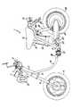
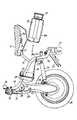
図1は本発明に係る電動二輪車の側面図、図2はバッテリ脱着時の状態を示す電動二輪車後部の破断側面図、図3は同電動二輪車のバッテリ部分のシートを取り除いた状態の部分平面図である。
【0012】
図1に示す電動二輪車1は、その車体前方上部にヘッドパイプ2を備え、該ヘッドパイプ2内には不図示のステアリング軸が回動自在に挿通している。そして、このステアリング軸の上端にはアッパーブラケット3が、下端にはアンダーブラケット4がそれぞれ取り付けられており、アッパーブラケット3にはハンドル5が取り付けられている。そして、ハンドル5の両端にはグリップ6が取り付けられており、左側のグリップ6の近傍にはブレーキレバー7が設けられており、不図示の右側(図1の奥側)のグリップ6は回動可能なスロットルグリップを構成している。
【0013】
又、前記アッパーブラケット3とアンダーブラケット4にはフロントフォーク8の上部が取り付けられており、該フロントフォーク8の下端には前輪9が前車軸10によって回転自在に軸支されている。尚、前記ハンドル5の前方のアッパーブラケット3上にはメータ11が配置され、該メータ11の下方には、前記フロントフォーク8の上部に固定されたヘッドランプ12が配され、その両側方にはフラッシャランプ13(図1には一方のみ図示)がそれぞれ設けられている。他方、前記ヘッドパイプ2からは側面視U字状を成す左右一対の車体フレーム14が車体後方に向かって延設されている。即ち、丸パイプ状の車体フレーム14は、ヘッドパイプ2から車体後方に向かって斜め下方に延びた後、後方に向かって円弧状に曲げられて車体後方に略水平に延びた後、上方に向かって円弧状に折り曲げられて車体後方に向かって斜め上方に立ち上がって側面視U字状を成している。そして、車体フレーム14の後端部14aは、シート15の形状に沿って屈曲され、左右の後端部14a同士は連続した1つのパイプを構成している。
【0014】
ところで、上記左右の車体フレーム14の後部近傍には、逆U字状を成すシートステー16(図3参照)が車体前方に向かって斜め上方に傾斜して溶着されており、このシートステー16と左右の車体フレーム14で囲まれる部分には前記シート15が開閉可能に配置されている。即ち、図2に示すように、前記シートステー16の前端水平部にはヒンジ17によってシート15の前端部が上下に回動可能に支持されており、該シート15のボトムプレート15aの下面にはクッション材18が取り付けられている。
【0015】
そして、車体フレーム14側には、シート15を支持するシートステー19とシート15を閉じ状態に固定ロックするための不図示のロック機構が設けられている。ここで、車体フレーム14の後端に取り付けられたリヤフェンダ20の後面にはテイルランプ21が取り付けられており、その左右にはフラッシャランプ22(図1及び図2には一方のみ図示)が配されている。
【0016】
一方、左右の車体フレーム14のシート15下方の屈曲部にはリヤアームブラケット23(図1及び図2には一方のみ図示)がそれぞれ溶着されており、左右一対のリヤアームブラケット23には、リヤアーム24の前端がピボット軸25にて上下揺動自在に支持されている。そして、このリヤアーム24の後端には駆動輪である後輪26が回転自在に軸支されており、リヤアーム24と後輪26はリヤクッション27によって車体フレーム14に懸架されている。
【0017】
又、左右の車体フレーム14の水平部にはフートステップ28(図1及び図2には一方のみ図示)がそれぞれ取り付けられており、左側の車体フレーム14のフートステップ28の後方にはサイドスタンド29が軸30によって回動可能に軸支されて設けられており、サイドスタンド29はリターンスプリング31によって閉じ側に付勢されている。
【0018】
ところで、本実施の形態に係る電動二輪車1においては、シート15の下方の左右の車体フレーム14の間にバッテリ32が脱着可能に配置されている。このバッテリ32は充電可能な複数の2次電池を収納して構成されており、その上面には傾倒自在なハンドル33が設けられている(図2及び図3参照)。又、バッテリ32の後面には、図3に示すように、上下方向に連続して形成された左右のリブ32aによって形成されたガイド溝が上下方向に貫設されている。
【0019】
一方、図1及び図2に示すように、前記シート15の下方の左右の車体フレーム14間には、上面が開口するカップ状のケース34が取り付けられており、このケース34には前記バッテリ32の下部が部分的に装着される。尚、図2に示すように、ケース34内には放電端子35が立設されており、バッテリ32を図1に示すようにケース34に収納すると、該バッテリ32の底面に埋設された不図示の放電端子がケース34側の前記放電端子35に接続される。
【0020】
又、上記ケース34の後部には、図2に示すように、車幅方向に広い板状のガイド部材36が車体後方に向かって斜め上方に立設されており、該ガイド部材36の上部は、車体フレーム14側に固定されたブラケット37によって支持されている。尚、ガイド部材36の上端部は車体後方に向かって円弧状に折り曲げられて導入部36aを構成している(図2参照)。
【0021】
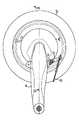
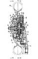
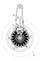
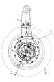
次に、後輪26を駆動する電動パワーユニットの構成を図4〜図10に基づいて説明する。尚、図4は電動二輪車の後輪部分の左側面図、図5は図4のA−A線断面図、図6は図5のB−B線矢視図、図7は図5のC−C線矢視図、図8は図7のD−D線断面図、図9はリヤブレーキの駆動系の構成を示す側面図、図10は遊星ギヤ減速機とワンウェイクラッチの構成を示す側面図である。
【0022】
前記リヤアーム24の略円形を成す後端部24aの右側端面には、図5に示すように、ギヤカバー38が被着され、その内部に形成された空間内に電動パワーユニットを構成する電動モータ39と遊星ギヤ減速機40及びコントローラ41が一体的に組み込まれている。
【0023】
駆動源としての上記電動モータ39には車幅方向に扁平な薄型のアキシャルギャップ型モータが使用され、図5に示すように、該電動モータ39は、リヤアーム24の後端部に支持された回転軸42に固定されたロータ39Aと、該ロータ39Aに対向してリヤアーム後端部24aの内面に固設されたステータ39Bとで構成されている。
【0024】
ここで、前記回転軸42は車幅方向に配され、その基端部はベアリング43によってリヤアーム24の後端部24aに回転自在に支承されており、前記ロータ39Aは、回転軸42にその中心部が結着されたヨーク39aと、該ヨーク39aの前記ステータ39Bに対向する外周面に固定されたマグネット39bとで構成されている。尚、ヨーク39aの中心部には凹部が形成されており、該凹部の外周フランジ部に前記マグネット39bが固定されている。
【0025】
又、前記ステータ39Bは、複数のコイル39cをリヤアーム24の後端部24a内面の回転軸42周りに同心円状に固設して構成されるが、図6に示すように、これらのコイル39cは側面視において車体前方(図6の右方)に向かって開放されたC字状に並設されており、その開放部分には前記コントローラ41の一部が臨んでいる。
【0026】
一方、前記遊星ギヤ減速機40は、図5に示すように、前記ロータ39Aのヨーク39a中央部に形成された凹部内に組み込まれており、該遊星ギヤ減速機40とロータ39Aに固定されたマグネット39bとは車幅方向において部分的にオーバーラップしている。
【0027】
ここで、遊星ギヤ減速機40は、図10に示すように、前記回転軸42に一体に形成された小径のサンギヤ42aと該サンギヤ42aに対して同心的に配設された大径のリングギヤ44及びサンギヤ42aとリングギヤ44に噛合する3つの遊星ギヤ45を含んで構成されており、これは前記電動モータ39に対して同軸的に配置されている。
【0028】
ところで、上記遊星ギヤ45は、図5に示すように、ピン46によってキャリア47に回転自在に支持されており、各遊星ギヤ45は、ピン46を中心として自転するとともに、サンギヤ42aの周りを公転し、ピン46を介してキャリア47に回転を伝達する。
【0029】
ここで、キャリア47の一部は前記回転軸42と同軸に配された後車軸47aを構成しており、この後車軸47aを含むキャリア47の全体は一対のベアリング48によって前記ギヤカバー38に回転自在に支持されている。
【0030】
又、前記リングギヤ44は回転可能に支持されており、その外周部には公知のワンウェイクラッチ49が介設されている。
【0031】
上記ワンウェイクラッチ49は、電動モータ39から後輪26方向への回転伝達を許容し、その逆方向への回転伝達を遮断するものであって、図10に示すように、前記リングギヤ44の外周に刻設されたラチェットギヤ44aと該ラチェットギヤ44aに選択的に噛合する複数のラチェット爪68で構成されている。ここで、各ラチェット爪68は、リング状のホルダ69に傾動自在に保持されており、不図示のスプリングによって付勢されて前記ラチェットギヤ44aに係合している。尚、ホルダ69は複数のビス70によって前記ギヤカバー38に取り付けられている。
【0032】
他方、前記後車軸47aのギヤカバー38外へ延出する端部には、前記後輪26がスプライン嵌合されてナット50によって結着されており、図5に示すように、後輪26のホイール51の内面に一体に形成されたドラム部51aの内部(ホイール51の内面とギヤカバー38との間に形成された空間)にはドラム式のリヤブレーキ52が組み込まれている。
【0033】
上記リヤブレーキ52は、図7に示すように、後輪26のホイール51の前記ドラム部51a内周に固設されたブレーキライニング53、該ブレーキライニング53の内側に配された2つの半月状ブレーキシュー54を備えており、2つのブレーキシュー54の一端同士は支持ピン55によって回動可能に連結され、他端部間にはカム56が介設されている。そして、両ブレーキシュー54は、これらに張架された2本のリターンスプリング57によって閉じ側(ブレーキ非作動側)に付勢されている。尚、前記支持ピン55は、図5に示すように、ボス58を介して前記ギヤカバー38に支持されている。
【0034】
ところで、図8に示すように、前記カム56は、ギヤカバー38に挿通固着されたボス59にその軸部(以下、カム軸と称する)56aが回動可能に挿通支持されており、該カム軸56aのギヤカバー38内の空間に臨む一端(左端)には図9に示すように扇形のセクタギヤ60が結着されている。
【0035】
一方、リヤアーム24の下部に一体に形成されたブラケット24b(図7及び図8参照)には、前記カム軸56aに対して車体後方にオフセットされたカムレバー軸61が回動可能に挿通支持されており、該カムレバー軸61のギヤカバー38内の空間の臨む一端(左端)には、図7及び図8に示すように、前記セクタギヤ60に噛合する扇形のセクタギヤ62が結着され、カムレバー軸61のリヤアーム24外へ突出する他端(右端)にはカムレバー63が結着されている。そして、このカムレバー63は、リターンスプリング64によって一方向(ブレーク非作動方向)に付勢されており、図4に示すブレーキワイヤー65を介して前記ブレーキレバー7(図1参照)に連結されている。尚、図8に示すように、前記セクタギヤ62は、前記電動モータ39のロータ39Aとの干渉を避けて直角に屈曲成形されている。
【0036】
ところで、前記コントローラ41は、前記電動モータ39を制御するものであって、これと前記電動モータ39とは図6に示す電極板66によって電気的に接続され、該コントローラ41と前記バッテリ32及び不図示の前記スロットルグリップとは図6に示す被覆線67によって電気的に接続されている。
【0037】
而して、電動二輪車1においては、バッテリ32からの電力の供給を受けて電動モータ39が回転駆動されると、その回転は遊星ギヤ減速機40によって減速されて後車軸47aに伝達され、該後車軸47aとこれに結着された後輪26が回転駆動されて当該電動二輪車1が所定の速度で走行せしめられる。そして、電動二輪車1の走行中にライダーがハンドル5に設けられた不図示のスロットルグリップを回して加減速操作すると、その操作信号がコントローラ41に伝達されて電動モータ39の回転及び後輪26の回転が制御されて電動二輪車1の車速が加減速される。
【0038】
又、ライダーが図1に示すブレーキレバー7を回動させて制動操作すると、図4に示すブレーキワイヤー65が引かれてカムレバー63が回動し、その回動はカムレバー軸61及びセクタギヤ62,60を経てカム56に伝達され、該カム56が回動する。すると、このカム56によってリヤブレーキ52のブレーキシュー54が押し開かれ、該ブレーキシュー54はリターンスプリング57の付勢力に抗して支持ピン55を中心に回動して拡開し、ブレーキライニング53の内周面に押圧される。この結果、ブレーキシュー54とブレーキライニング53間に摩擦力が発生し、この摩擦力によって後輪26の回転に所要の制動力が作用するため、電動二輪車1が減速或は停止せしめられる。
【0039】
ところで、使用によってバッテリ32の電圧が低下したために該バッテリ32の充電を行う場合には該バッテリ32を車体から取り外すが、このバッテリ32の取り外しは以下の要領でなされる。
【0040】
即ち、不図示のロック機構によるシート15のロックを解除した後、該シート15を図2に示すようにヒンジ17を中心として回動させてこれを開くと、バッテリ32の上方が開放される。
【0041】
次に、上記状態においてバッテリ32の上部に設けられたハンドル33を起こしてこれを把持し、該バッテリ32をガイド部材36に沿って上方に引き上げることによってこれを容易に取り外すことができ、取り外したバッテリ32を充電することができる。
【0042】
その後、バッテリ32の充電が終了して該バッテリ32を再び装着する際には、図2に示す状態において、バッテリ32をガイド部材36に沿って下方に摺動させてこれの下部をケース34に部分的に装着すれば良い。即ち、バッテリ32の後面をガイド部材36上端の導入部36aに当てて該バッテリ32をガイド部材36に沿って押し下げると、バッテリ32の後端面に貫設された前記ガイド溝がガイド部材36に嵌合するため、バッテリ32はガイド部材36にガイドされながらガタなくスムーズに摺動して装着され、該バッテリ32の底面に埋設された不図示の放電端子がケース34側の放電端子35に接続されてバッテリ32の使用が可能となる。
【0043】
そして、上述のようにしてバッテリ32が装着されると、シート15をヒンジ17を中心として回動させてこれを図1に示すように閉めると、該シート15の閉じ状態がロック機構によってロックされるとともに、シート15のボトムプレート15aに取り付けられたクッション材18がバッテリ32の上面を押圧して該バッテリ32を確実に保持する。
【0044】
以上において、本実施の形態によれば、図5に示すように、電動パワーユニットを構成する電動モータ39を薄型のアキシャルギャップ型モータで構成するとともに、該電動モータ39のロータ39A(ヨーク39a)の中央部に形成された凹部に遊星ギヤ減速機40を配置して該遊星ギヤ減速機40とロータ39Aに固定されたマグネット39bとを車幅方向において部分的にオーバーラップさせたため、電動パワーユニットの車幅方向寸法が縮小してその薄型化が実現される。
【0045】
ここで、本実施の形態に係る動力伝達装置の駆動系の構成を図10に模式的に示す。本実施の形態ではギヤ減速機としてサンギヤ42aとリングギヤ44及び遊星ギヤ45から成る遊星ギヤ減速機40を採用したが、ギヤ減速機としては図11に示す減速ギヤ群G1,G2,G3,G4から成るものを使用しても良い。
【0046】
即ち、図11に示すギヤ減速機においては、同軸に配された回転軸42と後車軸47aの相対向する端部には減速ギヤG1,G4がそれぞれ取り付けられており、回転軸42と後車軸47aに対して平行に配された回転軸71に回転自在に支持された減速ギヤG2,G3はそれぞれ減速ギヤG1,G4に噛合している。従って、電動モータの回転は、減速ギヤG1〜G4を経て減速されて後車軸47aとこれに結着された後輪26に伝達され、これらが所定の速度で回転駆動される。
【0047】
【発明の効果】
以上の説明で明らかなように、本発明によれば、電動モータと該電動モータの回転を減速して後車軸に伝達するギヤ減速機を含んで構成される電動パワーユニットをリヤアーム内に組み込み、リヤアームの後部から外側方に突出する前記後車軸の端部に後輪を取り付けて成る電動二輪車において、前記電動モータを、前記後車軸と同軸の回転軸と共に回転するロータを備えるアキシャルギャップ型モータで構成するとともに、前記ロータの中央に形成された凹部に前記ギヤ減速機を配置して該ギヤ減速機と前記ロータに固定されたマグネットとを車幅方向において部分的にオーバーラップさせたため、電動パワーユニットの車幅方向寸法が縮小してその薄型化が実現されるという効果が得られる。
【図面の簡単な説明】
【図1】本発明に係る電動二輪車の側面図である。
【図2】バッテリ脱着時の状態を示す電動二輪車後部の破断側面図である。
【図3】本発明に係る電動二輪車のバッテリ部分のシートを取り除いた状態の部分平面図である。
【図4】本発明に係る電動二輪車の後輪部分の左側面図である。
【図5】図4のA−A線断面図である。
【図6】図5のB−B線矢視図である。
【図7】図5のC−C線矢視図である。
【図8】図7のD−D線断面図である。
【図9】本発明に係る電動二輪車のリヤブレーキ駆動系の構成を示す側面図である。
【図10】遊星ギヤ減速機とワンウェイクラッチの構成を示す側面図である。
【図11】本発明の実施の形態に係る動力伝達装置の駆動系の構成を示す模式図である。
【図12】本発明に係る動力伝達装置の駆動系の他の構成例を示す模式図である。
【符号の説明】
1 電動二輪車
24 リヤアーム
26 後輪
39 電動モータ
39A ロータ
39B ステータ
39a ヨーク
39b マグネット
40 遊星ギヤ減速機(ギヤ減速機)
42 回転軸
42a サンギヤ
44 リングギヤ
45 遊星ギヤ
47a 後車軸
G1〜G4 減速ギヤ[0001]
BACKGROUND OF THE INVENTION
The present invention relates to a power transmission device for an electric motorcycle that travels using an electric motor as a drive source.
[0002]
[Prior art]
Conventionally, motorcycles mainly use an engine as a drive source, but from the viewpoint of environmental protection and the like, an electric motorcycle that runs using an electric motor as a drive source has been developed.
[0003]
As such an electric motorcycle, an electric power unit configured to include an electric motor and a speed reducer that decelerates the rotation of the electric motor and transmits it to the rear axle is incorporated in the rear arm, and the rear projecting outward from the rear portion of the rear arm. There has been proposed one in which a rear wheel is attached to an end portion of an axle.
[0004]
[Problems to be solved by the invention]
By the way, in the electric motorcycle described above, it is necessary to make the electric power unit as thin as possible because the electric power unit is incorporated in the rear arm.
[0005]
The present invention has been made in view of the above circumstances, and an object thereof is to provide a power transmission device for an electric two-wheeled vehicle capable of realizing a thin electric power unit.
[0006]
[Means for Solving the Problems]
In order to achieve the above object, according to a first aspect of the present invention, an electric power unit configured to include an electric motor and a gear reducer that decelerates the rotation of the electric motor and transmits it to the rear axle is incorporated in the rear arm. In the electric two-wheeled vehicle in which a rear wheel is attached to an end portion of the rear axle projecting outward from the rear portion, the electric motor is rotated with a rotary shaft coaxial with the rear axle, andopposed to the rotor. and fixed to a stator, constitutedby axial gap motor comprising,to form a recess recessed toward the stator side in the center of the rotor, a flange portion on the outer periphery of the recess facing the stator provided,along with arranging the gear reducer intherecess, a magnet fixed to the stator-side surface of the flange portion,tosaid reductiongear, Theaserial magnet andsaid stator, characterized in that partiallyoverlapped, respectively, in the vehicle width direction.
[0007]
A second aspect of the invention is characterized in that, in the first aspect of the invention, the gear reducer is a planetary gear reducer.
[0008]
According to a third aspect of the present invention, in the second aspect of the present invention, the electric motor and the planetary gear speed reducer are arranged coaxially.
[0009]
Therefore, according to the present invention,the electric motor constituting the electric powerunit, a rotor that rotates together with the rear axle coaxial with the rotation axis, the thinhaving a stator which is fixed to face the rotor, the axial constitutedby gapmotor, to form a recess recessed toward the stator side in the center of the rotor, the outer periphery of the recess is provided a flange portion facing the stator,said gear reducer tosaid recess Since themagnet is fixed to the stator side surface of the flange portion and the magnetand the statorare partially overlapped witheach other in the vehicle width directionwithrespect to the gear reducer, the electric power unit The vehicle width direction dimension is reduced and the thickness is reduced.
[0010]
DETAILED DESCRIPTION OF THE INVENTION
Embodiments of the present invention will be described below with reference to the accompanying drawings.
[0011]
FIG. 1 is a side view of an electric motorcycle according to the present invention, FIG. 2 is a cutaway side view of a rear portion of the electric motorcycle showing a state when the battery is detached, and FIG. 3 is a partial plan view of the electric motorcycle with a seat removed. It is.
[0012]
The
[0013]
An upper portion of a front fork 8 is attached to the
[0014]
By the way, in the vicinity of the rear part of the left and
[0015]
On the
[0016]
On the other hand, rear arm brackets 23 (only one is shown in FIGS. 1 and 2) are welded to the bent portions below the seat 15 of the left and
[0017]
In addition, foot steps 28 (only one is shown in FIGS. 1 and 2) are respectively attached to the horizontal portions of the left and
[0018]
By the way, in the
[0019]
On the other hand, as shown in FIGS. 1 and 2, a cup-
[0020]
Further, as shown in FIG. 2, a plate-
[0021]
Next, the configuration of the electric power unit that drives the
[0022]
As shown in FIG. 5, a
[0023]
The
[0024]
Here, the rotating
[0025]
The
[0026]
On the other hand, as shown in FIG. 5, the planetary
[0027]
Here, as shown in FIG. 10, the planetary
[0028]
As shown in FIG. 5, the
[0029]
Here, a part of the
[0030]
The
[0031]
The one-way clutch 49 allows rotation transmission from the
[0032]
On the other hand, the
[0033]
As shown in FIG. 7, the
[0034]
Incidentally, as shown in FIG. 8, the
[0035]
On the other hand, a
[0036]
By the way, the
[0037]
Thus, in the
[0038]
Further, when the rider turns the
[0039]
By the way, when charging the
[0040]
That is, after unlocking the seat 15 by a lock mechanism (not shown) and then rotating the seat 15 around the
[0041]
Next, in the above state, the
[0042]
Thereafter, when the charging of the
[0043]
When the
[0044]
In the above, according to the present embodiment, as shown in FIG. 5, the
[0045]
Here, FIG. 10 schematically shows the configuration of the drive system of the power transmission device according to the present embodiment. In this embodiment, the
[0046]
That is, in the gear reducer shown in FIG. 11, the reduction gears G1 and G4 are respectively attached to the opposite ends of the
[0047]
【The invention's effect】
As is apparent from the above description, according to the present invention, an electric power unit including an electric motor and a gear reducer that decelerates the rotation of the electric motor and transmits it to the rear axle is incorporated in the rear arm. In the electric two-wheeled vehicle in which a rear wheel is attached to an end portion of the rear axle projecting outward from the rear portion, the electric motor is constituted by an axial gap type motor including a rotor that rotates together with a rotation shaft coaxial with the rear axle. In addition, since the gear reducer is disposed in the recess formed in the center of the rotor and the gear reducer and the magnet fixed to the rotor are partially overlapped in the vehicle width direction, the electric power unit The effect that the vehicle width direction dimension reduces and the thickness reduction is implement | achieved is acquired.
[Brief description of the drawings]
FIG. 1 is a side view of an electric motorcycle according to the present invention.
FIG. 2 is a cutaway side view of the rear portion of the electric motorcycle showing a state when the battery is attached and detached.
FIG. 3 is a partial plan view of the electric motorcycle according to the present invention with the battery seat removed.
FIG. 4 is a left side view of a rear wheel portion of the electric motorcycle according to the present invention.
5 is a cross-sectional view taken along line AA in FIG.
6 is a view taken along the line BB in FIG.
7 is a view taken along the line CC of FIG.
8 is a cross-sectional view taken along the line DD of FIG.
FIG. 9 is a side view showing a configuration of a rear brake drive system of the electric motorcycle according to the present invention.
FIG. 10 is a side view showing configurations of a planetary gear reducer and a one-way clutch.
FIG. 11 is a schematic diagram showing a configuration of a drive system of the power transmission device according to the embodiment of the present invention.
FIG. 12 is a schematic diagram showing another configuration example of the drive system of the power transmission device according to the present invention.
[Explanation of symbols]
1
42
Claims (3)
Translated fromJapanese前記電動モータを、前記後車軸と同軸の回転軸と共に回転するロータと、該ロータに対向して固設されたステータと、を備えるアキシャルギャップ型モータで構成し、
前記ロータの中央に前記ステータ側に向けて窪む凹部を形成するとともに、該凹部の外周には前記ステータに対向するフランジ部を設け、
前記凹部に前記ギヤ減速機を配置するとともに、前記フランジ部の前記ステータ側の面にマグネットを固定し、
前記ギヤ減速機に対して、前記マグネットと前記ステータとを車幅方向においてそれぞれ部分的にオーバーラップさせたことを特徴とする電動二輪車の動力伝達装置。An electric power unit configured to include an electric motor and a gear reducer that decelerates the rotation of the electric motor and transmits it to the rear axle is incorporated in the rear arm, and the rear axle protrudes outward from the rear arm at the end of the rear axle. In an electric motorcycle with a rear wheel attached,
Said electric motor,a rotor that rotates together with the rear axle coaxial with the rotatingshaft, constitutedby axial gap motor comprisinga stator which is fixed to face the rotor, and
Forming a recess recessed toward the stator side in the center of the rotor, and providing a flange portion facing the stator on the outer periphery of the recess;
While disposingthe gear reducer in the recess,fix a magnet on the surface of the flange portion on the stator side,
The gearrelative to the reductiongear, the magnetand the stator and the power transmission device for an electric two-wheeled vehicle, characterized in that partiallyoverlapped, respectively, in the vehicle width direction.
Priority Applications (3)
| Application Number | Priority Date | Filing Date | Title |
|---|---|---|---|
| JP2002288395AJP3984139B2 (en) | 2001-10-19 | 2002-10-01 | Power transmission device for electric motorcycles |
| TW91123078ATWI232185B (en) | 2001-10-19 | 2002-10-07 | Power transmission device for electric two-wheeled bike |
| CN 02146507CN1215944C (en) | 2001-10-19 | 2002-10-17 | Power transmission device for electric two-wheeled bike |
Applications Claiming Priority (3)
| Application Number | Priority Date | Filing Date | Title |
|---|---|---|---|
| JP2001-322366 | 2001-10-19 | ||
| JP2001322366 | 2001-10-19 | ||
| JP2002288395AJP3984139B2 (en) | 2001-10-19 | 2002-10-01 | Power transmission device for electric motorcycles |
Publications (2)
| Publication Number | Publication Date |
|---|---|
| JP2003191883A JP2003191883A (en) | 2003-07-09 |
| JP3984139B2true JP3984139B2 (en) | 2007-10-03 |
Family
ID=26623998
Family Applications (1)
| Application Number | Title | Priority Date | Filing Date |
|---|---|---|---|
| JP2002288395AExpired - Fee RelatedJP3984139B2 (en) | 2001-10-19 | 2002-10-01 | Power transmission device for electric motorcycles |
Country Status (3)
| Country | Link |
|---|---|
| JP (1) | JP3984139B2 (en) |
| CN (1) | CN1215944C (en) |
| TW (1) | TWI232185B (en) |
Cited By (1)
| Publication number | Priority date | Publication date | Assignee | Title |
|---|---|---|---|---|
| US20220388597A1 (en)* | 2019-10-22 | 2022-12-08 | Karbon Kinetics Limited | Front Motor Drive Bicycle With Side Mounted Wheels |
Families Citing this family (17)
| Publication number | Priority date | Publication date | Assignee | Title |
|---|---|---|---|---|
| JP2003002277A (en)* | 2001-06-27 | 2003-01-08 | Yamaha Motor Co Ltd | Electric power unit, motor vehicle and power-assisted two wheeler |
| EP1653595A4 (en) | 2003-07-18 | 2012-06-27 | Yamaha Motor Co Ltd | Motor generator and electric vehicle having the same |
| JP2005143169A (en) | 2003-11-05 | 2005-06-02 | Yamaha Motor Co Ltd | Electric vehicle |
| TWI283103B (en) | 2004-02-06 | 2007-06-21 | Yamaha Motor Co Ltd | Rotating electric machine and electrically driven vehicle |
| JP2006050745A (en) | 2004-08-03 | 2006-02-16 | Nissan Motor Co Ltd | Axial gap rotating electric machine |
| JP4684598B2 (en)* | 2004-08-20 | 2011-05-18 | 本田技研工業株式会社 | Suspension device in fuel cell vehicle |
| JP2006191782A (en) | 2004-12-09 | 2006-07-20 | Yamaha Motor Co Ltd | Rotating-electric machine |
| JP4317536B2 (en) | 2005-06-23 | 2009-08-19 | ヤマハ発動機株式会社 | Hybrid motorcycle drive device and hybrid motorcycle equipped with the same |
| JP4762634B2 (en)* | 2005-08-05 | 2011-08-31 | ヤマハ発動機株式会社 | Electric small vehicle |
| JP5024811B2 (en) | 2006-03-17 | 2012-09-12 | 国立大学法人静岡大学 | Electric vehicle power supply device |
| AT508888B1 (en)* | 2009-05-20 | 2011-06-15 | Bionx Europ Gmbh | PLANETARY GEAR |
| JP5523770B2 (en)* | 2009-08-31 | 2014-06-18 | 本田技研工業株式会社 | Electric vehicle |
| CN102114771A (en)* | 2011-02-23 | 2011-07-06 | 奇瑞汽车股份有限公司 | Power assembly and electric vehicle using same |
| DE102011080037A1 (en) | 2011-07-28 | 2013-01-31 | Zf Friedrichshafen Ag | Vehicle axle for a motor vehicle |
| DE102012207775A1 (en) | 2012-05-10 | 2013-11-14 | Schaeffler Technologies AG & Co. KG | Electrical driven bicycle for use as electrical roller, has traction unit wheel arranged on side of wheel opposite to another side of wheel, where traction unit wheel is connected with wheel in torque-proof manner |
| JP6528642B2 (en) | 2015-10-27 | 2019-06-12 | スズキ株式会社 | Drive device for electric motorcycle and assembling method of drive device for electric motorcycle |
| WO2020213162A1 (en)* | 2019-04-19 | 2020-10-22 | ヤマハ発動機株式会社 | Straddled vehicle |
- 2002
- 2002-10-01JPJP2002288395Apatent/JP3984139B2/ennot_activeExpired - Fee Related
- 2002-10-07TWTW91123078Apatent/TWI232185B/ennot_activeIP Right Cessation
- 2002-10-17CNCN 02146507patent/CN1215944C/ennot_activeExpired - Fee Related
Cited By (1)
| Publication number | Priority date | Publication date | Assignee | Title |
|---|---|---|---|---|
| US20220388597A1 (en)* | 2019-10-22 | 2022-12-08 | Karbon Kinetics Limited | Front Motor Drive Bicycle With Side Mounted Wheels |
Also Published As
| Publication number | Publication date |
|---|---|
| JP2003191883A (en) | 2003-07-09 |
| CN1215944C (en) | 2005-08-24 |
| CN1412024A (en) | 2003-04-23 |
| TWI232185B (en) | 2005-05-11 |
Similar Documents
| Publication | Publication Date | Title |
|---|---|---|
| JP3984139B2 (en) | Power transmission device for electric motorcycles | |
| JP4499320B2 (en) | Vehicle wheel | |
| JP3705378B2 (en) | Electric wheelchair | |
| JP4460331B2 (en) | Motorcycle | |
| KR101465469B1 (en) | Independent power electric bicycle | |
| TW201233583A (en) | Electric saddle riding-type vehicle | |
| CN107792291A (en) | Wheel hub and power wheel comprising same | |
| JP3943196B2 (en) | Electric power unit | |
| JP2012214109A (en) | Electric three-wheeled vehicle | |
| JP2003127941A (en) | Battery attaching/detaching structure of electric two- wheeled vehicle | |
| JP3276081B2 (en) | Motorcycle with electric motor | |
| JP2007015422A (en) | Battery-assisted bicycle | |
| JP2019131166A (en) | Battery case structure of motorcycle | |
| JP3602824B2 (en) | Electric bicycle | |
| JP4244127B2 (en) | Brake device for electric motorcycle | |
| JP4109852B2 (en) | Throttle opening detection device for electric motorcycle | |
| JP3982607B2 (en) | Power transmission device for electric motorcycles | |
| JP2003134610A (en) | Drive control method for motorcycle | |
| JP4176339B2 (en) | Electric motorcycle frame structure | |
| JPH05105144A (en) | Motorcycle driven by electric motor | |
| JP4472093B2 (en) | Wheelchair fall prevention device | |
| JP4295015B2 (en) | Under-seat structure of motorcycle | |
| JP2004352188A (en) | Electric vehicle | |
| JPH06135369A (en) | Electric scooter | |
| JPH05105146A (en) | Motorcycle equipped with electric motor |
Legal Events
| Date | Code | Title | Description |
|---|---|---|---|
| A521 | Written amendment | Free format text:JAPANESE INTERMEDIATE CODE: A523 Effective date:20021121 | |
| A621 | Written request for application examination | Free format text:JAPANESE INTERMEDIATE CODE: A621 Effective date:20050617 | |
| RD02 | Notification of acceptance of power of attorney | Free format text:JAPANESE INTERMEDIATE CODE: A7422 Effective date:20060330 | |
| RD04 | Notification of resignation of power of attorney | Free format text:JAPANESE INTERMEDIATE CODE: A7424 Effective date:20060327 | |
| A131 | Notification of reasons for refusal | Free format text:JAPANESE INTERMEDIATE CODE: A131 Effective date:20061226 | |
| A977 | Report on retrieval | Free format text:JAPANESE INTERMEDIATE CODE: A971007 Effective date:20061228 | |
| A521 | Written amendment | Free format text:JAPANESE INTERMEDIATE CODE: A523 Effective date:20070215 | |
| TRDD | Decision of grant or rejection written | ||
| A01 | Written decision to grant a patent or to grant a registration (utility model) | Free format text:JAPANESE INTERMEDIATE CODE: A01 Effective date:20070703 | |
| A61 | First payment of annual fees (during grant procedure) | Free format text:JAPANESE INTERMEDIATE CODE: A61 Effective date:20070705 | |
| FPAY | Renewal fee payment (event date is renewal date of database) | Free format text:PAYMENT UNTIL: 20100713 Year of fee payment:3 | |
| R150 | Certificate of patent or registration of utility model | Free format text:JAPANESE INTERMEDIATE CODE: R150 | |
| FPAY | Renewal fee payment (event date is renewal date of database) | Free format text:PAYMENT UNTIL: 20110713 Year of fee payment:4 | |
| FPAY | Renewal fee payment (event date is renewal date of database) | Free format text:PAYMENT UNTIL: 20110713 Year of fee payment:4 | |
| FPAY | Renewal fee payment (event date is renewal date of database) | Free format text:PAYMENT UNTIL: 20120713 Year of fee payment:5 | |
| FPAY | Renewal fee payment (event date is renewal date of database) | Free format text:PAYMENT UNTIL: 20130713 Year of fee payment:6 | |
| R250 | Receipt of annual fees | Free format text:JAPANESE INTERMEDIATE CODE: R250 | |
| R250 | Receipt of annual fees | Free format text:JAPANESE INTERMEDIATE CODE: R250 | |
| R250 | Receipt of annual fees | Free format text:JAPANESE INTERMEDIATE CODE: R250 | |
| R250 | Receipt of annual fees | Free format text:JAPANESE INTERMEDIATE CODE: R250 | |
| LAPS | Cancellation because of no payment of annual fees |