JP3983722B2 - Engine intake control device - Google Patents
Engine intake control deviceDownload PDFInfo
- Publication number
- JP3983722B2 JP3983722B2JP2003285756AJP2003285756AJP3983722B2JP 3983722 B2JP3983722 B2JP 3983722B2JP 2003285756 AJP2003285756 AJP 2003285756AJP 2003285756 AJP2003285756 AJP 2003285756AJP 3983722 B2JP3983722 B2JP 3983722B2
- Authority
- JP
- Japan
- Prior art keywords
- permanent magnet
- shaft
- rotation angle
- control device
- magnetic flux
- Prior art date
- Legal status (The legal status is an assumption and is not a legal conclusion. Google has not performed a legal analysis and makes no representation as to the accuracy of the status listed.)
- Expired - Fee Related
Links
Images


Classifications
- F—MECHANICAL ENGINEERING; LIGHTING; HEATING; WEAPONS; BLASTING
- F16—ENGINEERING ELEMENTS AND UNITS; GENERAL MEASURES FOR PRODUCING AND MAINTAINING EFFECTIVE FUNCTIONING OF MACHINES OR INSTALLATIONS; THERMAL INSULATION IN GENERAL
- F16K—VALVES; TAPS; COCKS; ACTUATING-FLOATS; DEVICES FOR VENTING OR AERATING
- F16K27/00—Construction of housing; Use of materials therefor
- F16K27/02—Construction of housing; Use of materials therefor of lift valves
- F16K27/0209—Check valves or pivoted valves
- F16K27/0218—Butterfly valves
- F—MECHANICAL ENGINEERING; LIGHTING; HEATING; WEAPONS; BLASTING
- F02—COMBUSTION ENGINES; HOT-GAS OR COMBUSTION-PRODUCT ENGINE PLANTS
- F02D—CONTROLLING COMBUSTION ENGINES
- F02D9/00—Controlling engines by throttling air or fuel-and-air induction conduits or exhaust conduits
- F02D9/08—Throttle valves specially adapted therefor; Arrangements of such valves in conduits
- F02D9/10—Throttle valves specially adapted therefor; Arrangements of such valves in conduits having pivotally-mounted flaps
- F02D9/1035—Details of the valve housing
- F02D9/105—Details of the valve housing having a throttle position sensor
- F—MECHANICAL ENGINEERING; LIGHTING; HEATING; WEAPONS; BLASTING
- F02—COMBUSTION ENGINES; HOT-GAS OR COMBUSTION-PRODUCT ENGINE PLANTS
- F02D—CONTROLLING COMBUSTION ENGINES
- F02D9/00—Controlling engines by throttling air or fuel-and-air induction conduits or exhaust conduits
- F02D9/08—Throttle valves specially adapted therefor; Arrangements of such valves in conduits
- F02D9/10—Throttle valves specially adapted therefor; Arrangements of such valves in conduits having pivotally-mounted flaps
- F02D9/1065—Mechanical control linkage between an actuator and the flap, e.g. including levers, gears, springs, clutches, limit stops of the like
- F—MECHANICAL ENGINEERING; LIGHTING; HEATING; WEAPONS; BLASTING
- F16—ENGINEERING ELEMENTS AND UNITS; GENERAL MEASURES FOR PRODUCING AND MAINTAINING EFFECTIVE FUNCTIONING OF MACHINES OR INSTALLATIONS; THERMAL INSULATION IN GENERAL
- F16K—VALVES; TAPS; COCKS; ACTUATING-FLOATS; DEVICES FOR VENTING OR AERATING
- F16K27/00—Construction of housing; Use of materials therefor
- F16K27/02—Construction of housing; Use of materials therefor of lift valves
- F16K27/029—Electromagnetically actuated valves
- F—MECHANICAL ENGINEERING; LIGHTING; HEATING; WEAPONS; BLASTING
- F16—ENGINEERING ELEMENTS AND UNITS; GENERAL MEASURES FOR PRODUCING AND MAINTAINING EFFECTIVE FUNCTIONING OF MACHINES OR INSTALLATIONS; THERMAL INSULATION IN GENERAL
- F16K—VALVES; TAPS; COCKS; ACTUATING-FLOATS; DEVICES FOR VENTING OR AERATING
- F16K37/00—Special means in or on valves or other cut-off apparatus for indicating or recording operation thereof, or for enabling an alarm to be given
- F16K37/0025—Electrical or magnetic means
- F16K37/0033—Electrical or magnetic means using a permanent magnet, e.g. in combination with a reed relays
- F—MECHANICAL ENGINEERING; LIGHTING; HEATING; WEAPONS; BLASTING
- F16—ENGINEERING ELEMENTS AND UNITS; GENERAL MEASURES FOR PRODUCING AND MAINTAINING EFFECTIVE FUNCTIONING OF MACHINES OR INSTALLATIONS; THERMAL INSULATION IN GENERAL
- F16K—VALVES; TAPS; COCKS; ACTUATING-FLOATS; DEVICES FOR VENTING OR AERATING
- F16K37/00—Special means in or on valves or other cut-off apparatus for indicating or recording operation thereof, or for enabling an alarm to be given
- F16K37/0025—Electrical or magnetic means
- F16K37/0041—Electrical or magnetic means for measuring valve parameters
- F—MECHANICAL ENGINEERING; LIGHTING; HEATING; WEAPONS; BLASTING
- F16—ENGINEERING ELEMENTS AND UNITS; GENERAL MEASURES FOR PRODUCING AND MAINTAINING EFFECTIVE FUNCTIONING OF MACHINES OR INSTALLATIONS; THERMAL INSULATION IN GENERAL
- F16K—VALVES; TAPS; COCKS; ACTUATING-FLOATS; DEVICES FOR VENTING OR AERATING
- F16K37/00—Special means in or on valves or other cut-off apparatus for indicating or recording operation thereof, or for enabling an alarm to be given
- F16K37/0075—For recording or indicating the functioning of a valve in combination with test equipment
- F16K37/0083—For recording or indicating the functioning of a valve in combination with test equipment by measuring valve parameters
- Y—GENERAL TAGGING OF NEW TECHNOLOGICAL DEVELOPMENTS; GENERAL TAGGING OF CROSS-SECTIONAL TECHNOLOGIES SPANNING OVER SEVERAL SECTIONS OF THE IPC; TECHNICAL SUBJECTS COVERED BY FORMER USPC CROSS-REFERENCE ART COLLECTIONS [XRACs] AND DIGESTS
- Y10—TECHNICAL SUBJECTS COVERED BY FORMER USPC
- Y10T—TECHNICAL SUBJECTS COVERED BY FORMER US CLASSIFICATION
- Y10T137/00—Fluid handling
- Y10T137/8158—With indicator, register, recorder, alarm or inspection means
- Y10T137/8225—Position or extent of motion indicator
- Y10T137/8242—Electrical
Landscapes
- Engineering & Computer Science (AREA)
- General Engineering & Computer Science (AREA)
- Mechanical Engineering (AREA)
- Chemical & Material Sciences (AREA)
- Combustion & Propulsion (AREA)
- Physics & Mathematics (AREA)
- Electromagnetism (AREA)
- Control Of Throttle Valves Provided In The Intake System Or In The Exhaust System (AREA)
- Measurement Of Length, Angles, Or The Like Using Electric Or Magnetic Means (AREA)
- Transmission And Conversion Of Sensor Element Output (AREA)
- Combined Controls Of Internal Combustion Engines (AREA)
Description
Translated fromJapaneseこの発明は、吸気通路内の開口度を調整する絞り弁の回転角度を検出する回転角度検出センサを備えたエンジン用吸気制御装置に関するものである。 The present invention relates to an engine intake control device including a rotation angle detection sensor that detects a rotation angle of a throttle valve that adjusts an opening degree in an intake passage.
従来のエンジン用吸気制御装置では、シャフトに固定された絞り弁の回転角度を検出するセンサとして、ホール素子を備えた磁束密度検出型センサが用いられていた。
即ち、永久磁石および磁性体で構成した磁気回路を有する筒状の測定ターゲットを、駆動モータの駆動により回転するシャフトに固定された扇形形状の最終平歯車に設けるとともに、測定ターゲットの中心軸線上にホール素子を配設し、最終平歯車と連動した測定ターゲットの回転によりホール素子を通過する磁束密度の変化をホール素子が検出して絞り弁の回転角度を検出していた(例えば、特許文献1参照)。In a conventional engine intake control device, a magnetic flux density detection type sensor provided with a Hall element has been used as a sensor for detecting the rotation angle of a throttle valve fixed to a shaft.
That is, a cylindrical measurement target having a magnetic circuit composed of a permanent magnet and a magnetic body is provided on a fan-shaped final spur gear fixed to a shaft that rotates by driving of a drive motor, and on the central axis of the measurement target. A Hall element is provided, and the Hall element detects a change in magnetic flux density passing through the Hall element by the rotation of the measurement target interlocked with the final spur gear to detect the rotation angle of the throttle valve (for example, Patent Document 1). reference).
上記エンジン用吸気制御装置では、絞り弁の回転角度を検出するセンサは、シャフトを回転させる駆動モータの近傍に設けられているので、その駆動モータで発生した磁束の影響を受け、センサ出力が不安定になり、絞り弁の回転角度を正確に検出することができず、例えば必要とする空気吸入量が得られなくなるという問題点があった。 In the engine intake control device, the sensor that detects the rotation angle of the throttle valve is provided in the vicinity of the drive motor that rotates the shaft. Therefore, the sensor output is affected by the magnetic flux generated by the drive motor. There is a problem that the rotation angle of the throttle valve cannot be accurately detected, and the required air intake amount cannot be obtained, for example.
これに対しては、ホール素子の周囲を磁性体で囲って駆動モータからの磁束の影響を抑制することが想定されるが、上記エンジン用吸気制御装置では、測定ターゲットの中心軸線上にホール素子が配設されており、ホール素子は永久磁石からの磁束を周囲から受けているので、ホール素子の周囲を磁性体で囲んだ場合、ホール素子は、測定ターゲットの回転により通過する磁束密度の変化を正確に検出できなくなってしまうという問題点があった。 For this, it is assumed that the influence of the magnetic flux from the drive motor is suppressed by surrounding the hall element with a magnetic material. However, in the above intake control device for an engine, the hall element Since the Hall element receives magnetic flux from the permanent magnet from the surroundings, if the Hall element is surrounded by a magnetic material, the Hall element changes in the magnetic flux density that passes through the rotation of the measurement target. There is a problem that it becomes impossible to accurately detect.
この発明は、上記のような問題点を解決することを課題とするものであって、外部からの磁束の影響を抑え、外部からの磁束による回転角度検出センサの出力のバラツキを防止したエンジン用吸気制御装置を得るものである。 An object of the present invention is to solve the above-described problems, and is for an engine that suppresses the influence of magnetic flux from the outside and prevents variations in the output of the rotation angle detection sensor due to the magnetic flux from the outside. An intake control device is obtained.
この発明に係るエンジン用吸気制御装置では、シャフトと、このシャフトに固定され回転角度により吸気通路内の開口度を調整する絞り弁と、前記シャフトの端部にN極、S極が径方向に位置して設けられた永久磁石と、この永久磁石と平行に離間して設けられ永久磁石の磁束の方位の変化を検出する磁気抵抗素子を有するとともに前記絞り弁の回転角度を検出する回転角度検出センサと、この回転角度検出センサを前記永久磁石側が開口した開口面を有した状態で囲って設けられ永久磁石からの磁束の迂回通路となる磁性材で構成された迂回部材とを備え、前記吸気通路を有し、前記シャフト、前記絞り弁を収納したボディは、カバーで閉じられており、このカバーに前記回転角度検出センサがインサートモールド成形で一体化されており、また、前記回転角度検出センサは、前記迂回部材の内部でその中心よりも前記シャフトの軸線方向で前記永久磁石側に偏位して設けられている。
In the engine intake control device according to the present invention, a shaft, a throttle valve that is fixed to the shaft and adjusts an opening degree in the intake passage by a rotation angle, and an N pole and an S pole at the end of the shaft are in a radial direction. Rotation angle detection for detecting a rotation angle of the throttle valve having a permanent magnet provided in a position and a magnetoresistive element provided in parallel with the permanent magnet to detect a change in the direction of the magnetic flux of the permanent magnet A sensor and a detour member made of a magnetic material that surrounds the rotation angle detection sensor with an opening surface opened on the permanent magnet side and is a detour path for magnetic flux from the permanent magnet, and the intake air A body having a passage and housing the shaft and the throttle valve is closed by a cover, and the rotation angle detection sensor is integrated with the cover by insert molding. Further, the rotational angle detecting sensor, thethan inside the center of the bypass member is provided eccentrically on the permanent magnet sidein the axial direction of the shaft.
この発明に係るエンジン用吸気制御装置では、外部からの磁束の影響が抑えられ、外部からの磁束に起因した回転角度検出センサの出力のバラツキが防止される。 In the engine intake control device according to the present invention, the influence of the magnetic flux from the outside is suppressed, and variations in the output of the rotation angle detection sensor due to the magnetic flux from the outside are prevented.
実施の形態1.
以下、この発明の実施の形態1のエンジン用吸気制御装置(以下、吸気制御装置と呼ぶ。)について説明する。
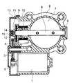
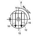
図1はこの吸気制御装置の側断面図、図2は図1のカバー13を取り除いたときの吸気制御装置の左側面図、図3は図1の要部拡大図である。
この吸気制御装置は、直流電流により駆動する駆動モータ1と、この駆動モータ1のシャフトに固定されたモータ平歯車2と、このモータ平歯車2と歯合した樹脂製の中間歯車3と、この中間歯車3と歯合し扇形形状の樹脂製の最終平歯車4と、この最終平歯車4に埋設された鋼材で形成された円板状のプレート5と、一端部に最終平歯車4が固定され他端部が軸受9を介してボディ8に回転自在に支持されたシャフト6と、シャフト6に螺子止めされ空気流量を調整する絞り弁7と、シャフト6の外周に設けられエンジンがアイドル回転速度の時の初期位置に戻すためのコイル状のリターンスプリング10とを備えている。シャフト6にはプレート5がかしめにより固定され、最終平歯車4はインサートモールド成形によりプレート5と一体化されている。
Hereinafter, an intake control device for an engine (hereinafter referred to as an intake control device) according to
FIG. 1 is a side sectional view of the intake control device, FIG. 2 is a left side view of the intake control device when the
The intake control device includes a
また、この吸気制御装置は、シャフト6の最終平歯車4側の端面に固定された受け部11と、この受け部11に嵌着された永久磁石12と、この永久磁石12と平行に離間して設けられているとともに磁束方位検出型の磁気抵抗素子を有する回転角度検出センサ(以下、センサと略称する。)14と、このセンサ14を永久磁石12側が開口した開口面を有した状態で囲って設けられ永久磁石12からの磁束の迂回通路となる磁性材で構成された有底円筒形状の迂回部材15とを備えている。
永久磁石12は、シャフト6に対し半径方向にN極/S極の極性となるように配置されている。永久磁石12は、直方体形状であり、センサ14との間の離間寸法でセンサ14に対する磁束密度が調整される。In addition, the intake control device includes a receiving
The
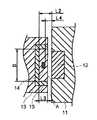
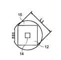
図5、図6は永久磁石12、センサ14および迂回部材15それぞれの配置関係を示す図であり、迂回部材15は、シャフト6の軸線方向から視てその内側に永久磁石12が配置されている。また、センサ14は、迂回部材15の内側でその中心よりも永久磁石12側に偏位して設けられている。そして、例えばL2=4〜6mm、L4=1.5〜2.5mm、L1=5〜10mm×5〜10mm、迂回部材15の内径D=8〜16mm、迂回部材15の円筒部長さL3=2〜3mmに設定される。 FIGS. 5 and 6 are diagrams showing the positional relationship among the
上記構成の吸気制御装置では、運転者がアクセルペダルを踏み込むと、アクセル開度センサ(図示せず)からのアクセル開度信号がエンジン制御装置(以下、ECUと呼ぶ)に入力される。ECUでは絞り弁7が所定の開度となるように駆動モータ1を通電し、駆動モータ1の出力軸が回転する。そして、出力軸が回転することにより、中間歯車3、最終平歯車4が回転する。これにより、最終平歯車4と一体のシャフト6が所定の回転角度だけ回転し、ボディ8に形成された吸気通路内において絞り弁7は所定の回転角度に保持される。
一方、センサ14は、シャフト6と一体的に回転する永久磁石12からの磁力線の方位を検出し、このセンサ14からECUに絞り弁7の開度信号を送る。この開度信号によってECUはどれだけ燃料をシリンダ内に噴射するかを判断する。In the intake control device having the above-described configuration, when the driver depresses the accelerator pedal, an accelerator opening signal from an accelerator opening sensor (not shown) is input to an engine control device (hereinafter referred to as ECU). In the ECU, the
On the other hand, the
上記構成の吸気制御装置では、磁束方位検出型であるセンサ14は、図3に示すように永久磁石12からの磁束の流れ16により磁束を受け、また図4に示すように磁束の動作範囲θ内で磁束の方位に応じて出力信号が変動する。具体的には、磁束の動作範囲θは絞り弁7が全閉である0°から全開である90°〜110°の範囲であり、この範囲でセンサ14はリニアリティに応答する。 In the intake control device having the above configuration, the
永久磁石12とセンサ14との位置関係は、シャフト6の軸線上に永久磁石12を配置し、またこの永久磁石12に対して平行に離間して、シャフト6の軸線上にセンサ14を設けたので、センサを筒状の測定ターゲットの中心に配置する必要性があった従来のものと比較して、永久磁石12およびセンサ14それぞれの組み付け精度が緩和され、製造コストが低減される。
このことは、インサートモールド成形でセンサ14と一体化されたカバー13のボディ8に対する組み付け、および最終平歯車4のシャフト6に対する組み付け精度の緩和でもあり、さらに雰囲気温度および吸水による寸法変化の影響が受け易い樹脂であってもカバー13および最終平歯車4の材料として使用することを可能とする。As for the positional relationship between the
This also means that the assembly of the
また、図3に示すように、迂回部材15は、永久磁石12側が開口した開口面Aを有した状態でセンサ14を囲っているので、永久磁石12による磁束により、磁束の流れ16とともに、迂回部材15にも磁路として通過する磁束の流れ17が発生する。このため、外部からセンサ14に向けて磁束が流入しょうとするとした場合、この外部磁束は、この磁束の流れ18に吸収される結果となり、センサ14に対する外部磁束の影響が抑制される。
また、永久磁石12から外部に漏れようとする磁束は迂回部材15に流れ、外部に漏れることも抑制される。
また、迂回部材15は、磁性材である低炭素鋼で構成されているので、加工性が良く、また安価に製造される。Further, as shown in FIG. 3, the
Further, the magnetic flux that is about to leak from the
Further, since the
実施の形態2.
図7はこの発明の実施の形態2の吸気制御装置の要部断面図、図8は図7の永久磁石12の磁束の流れをシャフト6の軸線方向から視たときの図である。
この実施の形態では、迂回部材18は、円板状の底部材19と、この底部材19に対して永久磁石12側に延びた円筒状の筒部材20との2部材から構成されている。
この底部材19、筒部材20はそれぞれ任意の位置に配置可能となり、配置の自由度が拡大し、永久磁石12の磁束の無駄をさらに低減でき、またセンサ14に対する外部磁束からの影響をさらに抑制することができ、永久磁石12の小型化、低コスト化が可能となる。
7 is a cross-sectional view of a main part of the intake air control device according to the second embodiment of the present invention, and FIG. 8 is a view when the flow of magnetic flux of the
In this embodiment, the
The
なお、上記の各実施の形態では磁気抵抗素子を用いて説明したが、巨大磁気抵抗素子を用いてもよい。
また、迂回部材15の形状については、勿論有底円筒形に限定されるものではなく、例えば有底四角形状のものであってもよい。In each of the above embodiments, a magnetoresistive element has been described. However, a giant magnetoresistive element may be used.
Of course, the shape of the
4 最終平歯車、6 シャフト、7 絞り弁、8 ボディ、12 永久磁石、13 カバー、14 回転角度検出センサ、15,18 迂回部材、19 底部材、20 筒部材。 4 Final spur gear, 6 shaft, 7 throttle valve, 8 body, 12 permanent magnet, 13 cover, 14 rotation angle detection sensor, 15, 18 detour member, 19 bottom member, 20 cylinder member.
Claims (3)
Translated fromJapaneseこのシャフトに固定され回転角度により吸気通路内の開口度を調整する絞り弁と、
前記シャフトの端部にN極、S極が径方向に位置して設けられた永久磁石と、
この永久磁石と平行に離間して設けられ永久磁石の磁束の方位の変化を検出する磁気抵抗素子を有するとともに前記絞り弁の回転角度を検出する回転角度検出センサと、
この回転角度検出センサを前記永久磁石側が開口した開口面を有した状態で囲って設けられ永久磁石からの磁束の迂回通路となる磁性材で構成された迂回部材と
を備え、
前記吸気通路を有し、前記シャフト、前記絞り弁を収納したボディは、カバーで閉じられており、このカバーに前記回転角度検出センサがインサートモールド成形で一体化されており、
また、前記回転角度検出センサは、前記迂回部材の内部でその中心よりも前記シャフトの軸線方向で前記永久磁石側に偏位して設けられているエンジン用吸気制御装置。A shaft,
A throttle valve that is fixed to the shaft and adjusts the opening degree in the intake passage according to the rotation angle;
A permanent magnet provided with an N pole and an S pole located in the radial direction at the end of the shaft;
A rotation angle detection sensor that includes a magnetoresistive element that is provided in parallel with the permanent magnet and detects a change in the direction of the magnetic flux of the permanent magnet, and that detects a rotation angle of the throttle valve;
A detour member made of a magnetic material that surrounds the rotation angle detection sensor in a state having an opening surface opened on the permanent magnet side, and is made of a magnetic material serving as a detour passage of magnetic flux from the permanent magnet,
A body having the intake passage and housing the shaft and the throttle valve is closed by a cover, and the rotation angle detection sensor is integrated with the cover by insert molding,
Further, the rotation angle detection sensor is an engine intake control device provided in the detour member so as to be deviatedtoward the permanent magnet side inthe axial direction of the shaft from the center thereof .
Priority Applications (2)
| Application Number | Priority Date | Filing Date | Title |
|---|---|---|---|
| JP2003285756AJP3983722B2 (en) | 2003-08-04 | 2003-08-04 | Engine intake control device |
| US10/765,392US7032617B2 (en) | 2003-08-04 | 2004-01-28 | Intake air control apparatus for an engine |
Applications Claiming Priority (1)
| Application Number | Priority Date | Filing Date | Title |
|---|---|---|---|
| JP2003285756AJP3983722B2 (en) | 2003-08-04 | 2003-08-04 | Engine intake control device |
Publications (2)
| Publication Number | Publication Date |
|---|---|
| JP2005054654A JP2005054654A (en) | 2005-03-03 |
| JP3983722B2true JP3983722B2 (en) | 2007-09-26 |
Family
ID=34113897
Family Applications (1)
| Application Number | Title | Priority Date | Filing Date |
|---|---|---|---|
| JP2003285756AExpired - Fee RelatedJP3983722B2 (en) | 2003-08-04 | 2003-08-04 | Engine intake control device |
Country Status (2)
| Country | Link |
|---|---|
| US (1) | US7032617B2 (en) |
| JP (1) | JP3983722B2 (en) |
Families Citing this family (40)
| Publication number | Priority date | Publication date | Assignee | Title |
|---|---|---|---|---|
| DE60309361T2 (en)* | 2002-03-06 | 2007-02-08 | Borgwarner Inc., Auburn Hills | Electronic throttle control with non-contact position transmitter |
| US7191754B2 (en)* | 2002-03-06 | 2007-03-20 | Borgwarner Inc. | Position sensor apparatus and method |
| US7307416B2 (en)* | 2004-10-22 | 2007-12-11 | Delphi Technologies, Inc. | Position sensor and assembly |
| US7909851B2 (en) | 2006-02-03 | 2011-03-22 | Biomet Sports Medicine, Llc | Soft tissue repair device and associated methods |
| US7749250B2 (en) | 2006-02-03 | 2010-07-06 | Biomet Sports Medicine, Llc | Soft tissue repair assembly and associated method |
| US8118836B2 (en) | 2004-11-05 | 2012-02-21 | Biomet Sports Medicine, Llc | Method and apparatus for coupling soft tissue to a bone |
| US7905904B2 (en) | 2006-02-03 | 2011-03-15 | Biomet Sports Medicine, Llc | Soft tissue repair device and associated methods |
| US8088130B2 (en) | 2006-02-03 | 2012-01-03 | Biomet Sports Medicine, Llc | Method and apparatus for coupling soft tissue to a bone |
| US8128658B2 (en) | 2004-11-05 | 2012-03-06 | Biomet Sports Medicine, Llc | Method and apparatus for coupling soft tissue to bone |
| US9017381B2 (en) | 2007-04-10 | 2015-04-28 | Biomet Sports Medicine, Llc | Adjustable knotless loops |
| DE102005059538B4 (en) | 2005-12-13 | 2018-08-23 | Asm Automation Sensorik Messtechnik Gmbh | Hinge sensor |
| US11259792B2 (en) | 2006-02-03 | 2022-03-01 | Biomet Sports Medicine, Llc | Method and apparatus for coupling anatomical features |
| US8801783B2 (en) | 2006-09-29 | 2014-08-12 | Biomet Sports Medicine, Llc | Prosthetic ligament system for knee joint |
| ES2333355T3 (en)* | 2006-08-02 | 2010-02-19 | MAGNETI MARELLI S.p.A. | VARIABLE GEOMETRY ADMISSION COLLECTOR FOR AN INTERNAL COMBUSTION ENGINE. |
| US11259794B2 (en) | 2006-09-29 | 2022-03-01 | Biomet Sports Medicine, Llc | Method for implanting soft tissue |
| PL1908943T3 (en)* | 2006-10-05 | 2009-06-30 | Magneti Marelli Spa | Variable geometry intake manifold for an internal combustion engine |
| EP1916400A1 (en)* | 2006-10-27 | 2008-04-30 | Magneti Marelli Holding S.p.A. | Variable geometry intake manifold with integrated actuator for an internal combustion engine |
| EP2000781B2 (en)* | 2007-06-04 | 2013-03-13 | Magneti Marelli S.p.A. | A manufacturing method of a shaft provided with a magnet for an air flow rate adjustment valve in an internal combustion engine |
| US8933691B2 (en)* | 2007-10-27 | 2015-01-13 | Walbro Engine Management, L.L.C. | Rotary position sensor |
| US8857464B2 (en)* | 2008-01-30 | 2014-10-14 | Flowserve Management Company | Valve actuators having magnetic angle sensors |
| EP2742223A4 (en) | 2011-08-08 | 2016-05-04 | Husqvarna Ab | A magnet holder for use in a throttle position sensor, a magnet holder for use in an angular position sensor, and methods for manufacturing them |
| US9381013B2 (en) | 2011-11-10 | 2016-07-05 | Biomet Sports Medicine, Llc | Method for coupling soft tissue to a bone |
| JP5741961B2 (en)* | 2012-10-24 | 2015-07-01 | 株式会社デンソー | Rotation angle detection device and rotation drive device using the same |
| KR101327038B1 (en)* | 2013-06-03 | 2013-11-07 | 주식회사 현대케피코 | Electronic throttle assembly |
| US9341282B2 (en)* | 2013-08-20 | 2016-05-17 | Flow Control Industries, Inc. | Off-axis position monitoring and control system and related methods |
| US10102992B2 (en)* | 2014-02-25 | 2018-10-16 | Infineon Technologies Ag | Switching apparatus, switching system and switching method |
| CN105782554A (en)* | 2014-12-22 | 2016-07-20 | 中核苏阀科技实业股份有限公司 | Check valve non-contact switch indicating structure |
| US9933088B2 (en)* | 2015-06-10 | 2018-04-03 | Woodward, Inc. | Rotary actuated valve with position indicator |
| DE102015213828A1 (en)* | 2015-07-22 | 2017-01-26 | Mahle International Gmbh | Assembly for an adjusting device, in particular an exhaust gas turbocharger, and method for producing such an assembly |
| JP6129276B1 (en)* | 2015-11-04 | 2017-05-17 | 三菱電機株式会社 | Non-contact rotation angle detector |
| JP6741611B2 (en)* | 2017-02-20 | 2020-08-19 | 株式会社不二工機 | Motorized valve |
| EP3382248B1 (en)* | 2017-03-30 | 2020-04-29 | Hamilton Sundstrand Corporation | Rotary actuation mechanism |
| JP6826727B2 (en) | 2017-03-31 | 2021-02-10 | 株式会社不二工機 | Solenoid valve |
| US10107415B1 (en)* | 2017-11-13 | 2018-10-23 | Flowserve Management Company | Anti-backlash valve positioner |
| WO2020039564A1 (en)* | 2018-08-23 | 2020-02-27 | 株式会社ミクニ | Electronically controlled throttle device for engine |
| CN110220026B (en)* | 2019-05-17 | 2021-09-17 | 陕西科技大学 | Butterfly type pneumatic program control valve body |
| JP7259637B2 (en)* | 2019-08-19 | 2023-04-18 | 株式会社デンソーダイシン | Throttle valve device |
| CN111536289B (en)* | 2020-04-29 | 2021-09-28 | 中国核动力研究设计院 | Intelligent valve position indicator and automatic compensation control method |
| WO2022265920A1 (en)* | 2021-06-18 | 2022-12-22 | Victaulic Company | Calibrated flow rate sensing and flow control device |
| DE102022103766A1 (en) | 2022-02-17 | 2023-08-17 | Fte Automotive Gmbh | Assembly with a shaft and a magnet attached to it |
Family Cites Families (11)
| Publication number | Priority date | Publication date | Assignee | Title |
|---|---|---|---|---|
| US3602254A (en)* | 1970-01-30 | 1971-08-31 | Pratt Co Henry | Valve position indicating system |
| JPS56107119A (en)* | 1980-01-30 | 1981-08-25 | Nippon Denso Co Ltd | Detecting device for rotational angle |
| DE4014885C2 (en)* | 1989-05-13 | 1995-07-13 | Aisan Ind | Angle of rotation sensor |
| JPH0466813A (en)* | 1990-07-06 | 1992-03-03 | Mitsubishi Electric Corp | Angle detecting sensor |
| US5332965A (en)* | 1992-06-22 | 1994-07-26 | Durakool Incorporated | Contactless linear angular position sensor having an adjustable flux concentrator for sensitivity adjustment and temperature compensation |
| DE9317797U1 (en)* | 1993-11-20 | 1994-02-03 | Ab Elektronik Gmbh, 59368 Werne | Throttle valve assembly |
| US6483296B1 (en)* | 1999-06-17 | 2002-11-19 | Denso Corporation | Angular position detection apparatus |
| JP3491596B2 (en)* | 1999-06-28 | 2004-01-26 | 株式会社デンソー | Rotation angle detector |
| JP2001289610A (en)* | 1999-11-01 | 2001-10-19 | Denso Corp | Rotation angle detector |
| JP2001132494A (en) | 1999-11-01 | 2001-05-15 | Denso Corp | Intake control device for internal combustion engine |
| DE10135784B4 (en)* | 2000-07-26 | 2015-09-17 | Ntn Corp. | Bearing provided with a rotation sensor and motor equipped therewith |
- 2003
- 2003-08-04JPJP2003285756Apatent/JP3983722B2/ennot_activeExpired - Fee Related
- 2004
- 2004-01-28USUS10/765,392patent/US7032617B2/ennot_activeExpired - Fee Related
Also Published As
| Publication number | Publication date |
|---|---|
| US7032617B2 (en) | 2006-04-25 |
| US20050028871A1 (en) | 2005-02-10 |
| JP2005054654A (en) | 2005-03-03 |
Similar Documents
| Publication | Publication Date | Title |
|---|---|---|
| JP3983722B2 (en) | Engine intake control device | |
| JP2005048671A (en) | Engine intake control system | |
| US7231904B2 (en) | Relative position detection and control device for motor vehicle | |
| JP3893907B2 (en) | Intake control device for internal combustion engine | |
| JP4098149B2 (en) | Throttle control device | |
| US7675283B2 (en) | Relative position detection device for motor vehicle | |
| US7671584B2 (en) | Rotation angle detection device | |
| JP2005147926A (en) | Rotational position sensor and electronically controlled throttle device for internal combustion engine | |
| JP2004028809A (en) | Actuator | |
| US6930477B1 (en) | Rotation angle detection device | |
| JP4391065B2 (en) | Throttle opening detection device | |
| US6396260B1 (en) | Measuring device for contactless detection of a rotational angle | |
| US20070108968A1 (en) | Rotation angle detection device | |
| JP2008128823A (en) | Rotation angle detector | |
| US9228502B2 (en) | Accelerator apparatus for vehicle | |
| JP4046746B2 (en) | Rotation angle detector | |
| JP5720961B2 (en) | Position detection device | |
| JP4638523B2 (en) | Method for manufacturing throttle opening detection device | |
| JP2008128857A (en) | Rotation angle detector | |
| JP5720962B2 (en) | Position detection device | |
| JP4215783B2 (en) | Throttle valve control device for internal combustion engine | |
| JP4249758B2 (en) | Rotation angle detector | |
| JP2001208510A (en) | Angle-of-rotation detector | |
| US20230349685A1 (en) | Rotation Angle Detecting Device | |
| JPS6281502A (en) | Rotation angle detector |
Legal Events
| Date | Code | Title | Description |
|---|---|---|---|
| A621 | Written request for application examination | Free format text:JAPANESE INTERMEDIATE CODE: A621 Effective date:20050720 | |
| A977 | Report on retrieval | Free format text:JAPANESE INTERMEDIATE CODE: A971007 Effective date:20060626 | |
| A131 | Notification of reasons for refusal | Free format text:JAPANESE INTERMEDIATE CODE: A131 Effective date:20060704 | |
| A521 | Written amendment | Free format text:JAPANESE INTERMEDIATE CODE: A523 Effective date:20060904 | |
| A02 | Decision of refusal | Free format text:JAPANESE INTERMEDIATE CODE: A02 Effective date:20061219 | |
| A521 | Written amendment | Free format text:JAPANESE INTERMEDIATE CODE: A523 Effective date:20070219 | |
| A911 | Transfer to examiner for re-examination before appeal (zenchi) | Free format text:JAPANESE INTERMEDIATE CODE: A911 Effective date:20070223 | |
| A131 | Notification of reasons for refusal | Free format text:JAPANESE INTERMEDIATE CODE: A131 Effective date:20070515 | |
| A521 | Written amendment | Free format text:JAPANESE INTERMEDIATE CODE: A523 Effective date:20070615 | |
| TRDD | Decision of grant or rejection written | ||
| A01 | Written decision to grant a patent or to grant a registration (utility model) | Free format text:JAPANESE INTERMEDIATE CODE: A01 Effective date:20070703 | |
| A61 | First payment of annual fees (during grant procedure) | Free format text:JAPANESE INTERMEDIATE CODE: A61 Effective date:20070704 | |
| FPAY | Renewal fee payment (event date is renewal date of database) | Free format text:PAYMENT UNTIL: 20100713 Year of fee payment:3 | |
| R150 | Certificate of patent or registration of utility model | Ref document number:3983722 Country of ref document:JP Free format text:JAPANESE INTERMEDIATE CODE: R150 Free format text:JAPANESE INTERMEDIATE CODE: R150 | |
| FPAY | Renewal fee payment (event date is renewal date of database) | Free format text:PAYMENT UNTIL: 20100713 Year of fee payment:3 | |
| FPAY | Renewal fee payment (event date is renewal date of database) | Free format text:PAYMENT UNTIL: 20110713 Year of fee payment:4 | |
| FPAY | Renewal fee payment (event date is renewal date of database) | Free format text:PAYMENT UNTIL: 20110713 Year of fee payment:4 | |
| FPAY | Renewal fee payment (event date is renewal date of database) | Free format text:PAYMENT UNTIL: 20120713 Year of fee payment:5 | |
| FPAY | Renewal fee payment (event date is renewal date of database) | Free format text:PAYMENT UNTIL: 20120713 Year of fee payment:5 | |
| FPAY | Renewal fee payment (event date is renewal date of database) | Free format text:PAYMENT UNTIL: 20130713 Year of fee payment:6 | |
| R250 | Receipt of annual fees | Free format text:JAPANESE INTERMEDIATE CODE: R250 | |
| R250 | Receipt of annual fees | Free format text:JAPANESE INTERMEDIATE CODE: R250 | |
| R250 | Receipt of annual fees | Free format text:JAPANESE INTERMEDIATE CODE: R250 | |
| R250 | Receipt of annual fees | Free format text:JAPANESE INTERMEDIATE CODE: R250 | |
| LAPS | Cancellation because of no payment of annual fees |