JP3977303B2 - Position detection system, transmitter and receiver in position detection system - Google Patents
Position detection system, transmitter and receiver in position detection systemDownload PDFInfo
- Publication number
- JP3977303B2 JP3977303B2JP2003297714AJP2003297714AJP3977303B2JP 3977303 B2JP3977303 B2JP 3977303B2JP 2003297714 AJP2003297714 AJP 2003297714AJP 2003297714 AJP2003297714 AJP 2003297714AJP 3977303 B2JP3977303 B2JP 3977303B2
- Authority
- JP
- Japan
- Prior art keywords
- wave
- reflector
- receiving
- detection system
- transmitting
- Prior art date
- Legal status (The legal status is an assumption and is not a legal conclusion. Google has not performed a legal analysis and makes no representation as to the accuracy of the status listed.)
- Expired - Fee Related
Links
Images


Classifications
- G—PHYSICS
- G01—MEASURING; TESTING
- G01S—RADIO DIRECTION-FINDING; RADIO NAVIGATION; DETERMINING DISTANCE OR VELOCITY BY USE OF RADIO WAVES; LOCATING OR PRESENCE-DETECTING BY USE OF THE REFLECTION OR RERADIATION OF RADIO WAVES; ANALOGOUS ARRANGEMENTS USING OTHER WAVES
- G01S17/00—Systems using the reflection or reradiation of electromagnetic waves other than radio waves, e.g. lidar systems
- G01S17/02—Systems using the reflection of electromagnetic waves other than radio waves
- G01S17/06—Systems determining position data of a target
- G01S17/46—Indirect determination of position data
- G01S17/48—Active triangulation systems, i.e. using the transmission and reflection of electromagnetic waves other than radio waves
- G—PHYSICS
- G01—MEASURING; TESTING
- G01S—RADIO DIRECTION-FINDING; RADIO NAVIGATION; DETERMINING DISTANCE OR VELOCITY BY USE OF RADIO WAVES; LOCATING OR PRESENCE-DETECTING BY USE OF THE REFLECTION OR RERADIATION OF RADIO WAVES; ANALOGOUS ARRANGEMENTS USING OTHER WAVES
- G01S17/00—Systems using the reflection or reradiation of electromagnetic waves other than radio waves, e.g. lidar systems
- G01S17/003—Bistatic lidar systems; Multistatic lidar systems
Landscapes
- Physics & Mathematics (AREA)
- Electromagnetism (AREA)
- Engineering & Computer Science (AREA)
- Computer Networks & Wireless Communication (AREA)
- General Physics & Mathematics (AREA)
- Radar, Positioning & Navigation (AREA)
- Remote Sensing (AREA)
- Optical Radar Systems And Details Thereof (AREA)
- Radar Systems Or Details Thereof (AREA)
Description
Translated fromJapanese本発明は、位置検出システム、位置検出システムにおける発信装置および受信装置に関し、特に、空間を伝播する波動を反射する反射体を備えた移動体の位置を検出する位置検出システム、位置検出システムにおける発信装置および受信装置に関する。 The present invention relates to a position detection system, a transmission device in the position detection system, and a reception device, and in particular, a position detection system that detects a position of a moving body including a reflector that reflects a wave propagating in space, and transmission in the position detection system. The present invention relates to a device and a receiving device.
従来より、移動体の位置を計測する位置計測装置や、移動体との距離を測定する距離測定装置が知られている。これらの装置は、レーザ等の光を移動体に対して照射し、移動体に設けられた反射体で反射した反射光の入射角度を用いて移動体の位置や距離を測定している。 Conventionally, a position measuring device that measures the position of a moving body and a distance measuring device that measures a distance from the moving body are known. These apparatuses irradiate a moving body with light such as a laser, and measure the position and distance of the moving body using the incident angle of reflected light reflected by a reflector provided on the moving body.
特開平6−59016号公報(特許文献1)は、予め反射器の位置を測定して回路に登録する手続きが不要であり、高精度の測定結果を得ることが出来る移動体の位置計測装置を開示する。特許文献1に開示された位置計測装置は、移動体上から光ビームを回転走査して出射し、移動体とは離隔して別体に配置した少なくとも3つの光反射器からの反射光を移動体上にて検知し、各光反射器の位置と光反射器間の開き角度に基づいて、移動体の現在位置を計測する装置である。この装置は、移動体が第1の基準位置に設置された状態で、各光反射器からの反射光の移動体に対する入射角度θ(1)を検知すると共に、移動体が第1基準位置から離れた第2の基準位置に設置された状態で、各光反射器からの反射光の移動体に対する入射角度θ(2)を検知する光検知部と、第1基準位置と第2基準位置の間隔a、及び両基準位置における各光反射器についての入射角度θ(1)、θ(2)に基づいて、各光反射器の位置を算出する演算部とを含む。 Japanese Patent Laid-Open No. 6-59016 (Patent Document 1) does not require a procedure for measuring the position of a reflector in advance and registering it in a circuit, and provides a position measuring apparatus for a moving body that can obtain a highly accurate measurement result. Disclose. The position measurement device disclosed in
この公報に開示された発明によると、移動体の位置計測に際しては、先ず、少なくとも3個の光反射器が移動体の移動平面上の任意位置に設置される。そして、移動体が第1の基準位置に設置され、この状態で、光ビームを回転走査して出射し、各光反射器からの反射光を受光する。この結果、各光反射器について、第1基準位置の移動体に対する反射光の入射角度θ(1)が検知される。次に、移動体が第2の基準位置に設置され、この状態で、光ビームを回転走査して出射し、各光反射器からの反射光を受光する。この結果、各光反射器について、第2基準位置の移動体に対する反射光の入射角度θ(2)が検知される。ここで、第1基準位置と第2基準位置の間隔aは、光反射器間の距離に比べて充分に小さく設定でき、周知の測長手段、例えば移動体に設けたロータリエンコーダ等によって高精度に測定することが出来る。次に、上記の入射角度θ(1)、θ(2)の測定結果に基づいて、各光反射器の位置が算出される。この際、任意の一つの光反射器の位置は、両基準位置の間隔aと、光反射器についての2つの入射角度θ(1)及びθ(2)によって規定されるから、これらのデータに基づいて光反射器のX−Y座標が算出される。その後、移動体の位置計測に移行し、光ビームの回転走査に伴って各反射器からの反射光が検知され、各光反射器の位置(X−Y座標)と光反射器間の開き角度に基づいて、移動体の現在位置が算出される。その結果、移動体の位置計測に先立って、各光反射器の位置が光計測によって高精度に測定され、測定データに基づいて移動体の位置が算出されるから、高精度の測定結果を得ることが出来る。しかも、光反射器の位置測定及び登録手続きは不要である。 According to the invention disclosed in this publication, when measuring the position of the moving body, first, at least three light reflectors are installed at arbitrary positions on the moving plane of the moving body. Then, the moving body is installed at the first reference position, and in this state, the light beam is rotationally scanned and emitted, and the reflected light from each light reflector is received. As a result, the incident angle θ (1) of the reflected light with respect to the moving body at the first reference position is detected for each light reflector. Next, the moving body is installed at the second reference position, and in this state, the light beam is rotationally scanned and emitted, and the reflected light from each light reflector is received. As a result, the incident angle θ (2) of the reflected light with respect to the moving body at the second reference position is detected for each light reflector. Here, the distance a between the first reference position and the second reference position can be set sufficiently smaller than the distance between the light reflectors, and is highly accurate by a known length measuring means, for example, a rotary encoder provided on the moving body. Can be measured. Next, the position of each light reflector is calculated based on the measurement results of the incident angles θ (1) and θ (2). At this time, the position of any one light reflector is defined by the interval a between both reference positions and the two incident angles θ (1) and θ (2) with respect to the light reflector. Based on this, the XY coordinates of the light reflector are calculated. After that, the process moves to the position measurement of the moving body, and the reflected light from each reflector is detected along with the rotational scanning of the light beam, and the opening angle between the position of each light reflector (XY coordinate) and the light reflector. Based on the above, the current position of the moving body is calculated. As a result, prior to measuring the position of the moving body, the position of each light reflector is measured with high accuracy by optical measurement, and the position of the moving body is calculated based on the measurement data, so that a highly accurate measurement result is obtained. I can do it. In addition, no optical reflector position measurement and registration procedure is required.
特開平6−317670号公報(特許文献2)は、目測等の人的手段を全く用いず、また車間距離算出の演算時間が短く、構成が簡単な車間距離測定装置を開示する。特許文献2に記載の車間距離測定装置は、車両の略前方に向けてレーザ光を発射するレーザ光送信部と、レーザ光を掃引する掃引部と、レーザ光送信部により発射されたレーザ光のうち、先行車両の後部に取り付けられた反射器に反射して返ってきたレーザ光を受信するレーザ光受信部と、レーザ光受信手段により受信された信号の到達方向から反射器の存在する角度を検出する角度検出部とをそれぞれ2つずつ備え、2つの角度検出手段がそれぞれ検出した角度とあらかじめメモリ内に記憶した2つのレーザ光送信手段の間隔から先行車両との車間距離を算出する車間距離算出部を備えている。 Japanese Laid-Open Patent Publication No. 6-317670 (Patent Document 2) discloses an inter-vehicle distance measuring device that uses no human means such as eye measurement, has a short calculation time for calculating an inter-vehicle distance, and has a simple configuration. The inter-vehicle distance measuring device described in
この公報に開示された発明によると、先行車両の後部の反射器にレーザ光線等のビームを照射し、反射器の存在する方向を検知して、この角度と反射器の間隔から、車間距離を測定するので、従来のように目測で車間距離を割り出すよりもはるかに精度よく、正確に車間距離を求めることができる。また、車両にレーザ光照射部を2つ設け、それぞれ独立して先行車両の反射器の存在する角度を求めることで、単車のような1つしか反射器が存在しないような先行車両についても、正確に車間距離を求めることができる。
しかしながら、特開平6−59016号公報に記載の位置計測装置においては、光反射器から反射光を移動体上にて検知しているため、予め光反射器を設置しておく必要があり、限られた範囲内でのみ移動する移動体の位置しか計測することができず、任意の場所を移動する移動体の位置を計測できないという問題点があった。 However, in the position measuring apparatus described in JP-A-6-59016, since the reflected light is detected on the moving body from the light reflector, it is necessary to install the light reflector in advance. There is a problem that only the position of a moving body that moves within a given range can be measured, and the position of a moving body that moves in an arbitrary place cannot be measured.
また、特開平6−317670号公報に記載の位置計測装置においては、2つのレーザ光受信部部がそれぞれ反射光を受信し、反射器の存在する角度を検出している。そのため、反射光を用いた角度の検出を合計2回実行することとなる。通常、レーザを含む光は、空間を進む際にぶれが生じてしまうため、反射光を用いて反射器の存在する角度を検出する場合、ぶれの分だけ誤差が含まれることになる。その結果、特開平6−317670号公報に記載の位置計測装置においては、ぶれによる誤差を2回分含むことになり、誤差が大きくなるという問題点があった。 Further, in the position measuring apparatus described in Japanese Patent Laid-Open No. 6-317670, two laser light receiving units each receive reflected light and detect an angle at which a reflector exists. Therefore, the angle detection using the reflected light is executed twice in total. Normally, light including a laser is shaken when traveling through space. Therefore, when an angle at which a reflector exists is detected using reflected light, an error corresponding to the shake is included. As a result, the position measuring apparatus described in Japanese Patent Laid-Open No. 6-317670 has a problem that an error due to shaking is included twice and the error becomes large.
本発明は上述の問題点を解決するためになされたものであって、その目的は、任意の場所を移動する移動体の位置を小さい誤差で検出することができる位置検出システムを提供することにある。 The present invention has been made to solve the above-described problems, and an object of the present invention is to provide a position detection system that can detect the position of a moving body that moves in an arbitrary place with a small error. is there.
第1の発明に係る位置検出システムは、発信装置と、受信装置と、それらの装置を用いて位置が検出される移動体とを含む位置検出システムである。移動体は、空間を伝播する波動を反射する反射体を備えている。発信装置は、波動を発信するための発信手段と、波動を発信する方向を検出するための手段とを含む。受信装置は、反射体により反射された波動の反射波を受信するための受信手段と、反射波を受信する方向を検出するための方向検出手段を含む。発信装置と受信装置とは離隔して設けられている。発信装置と受信装置と移動体のうちの少なくともいずれか1つは、波動を発信する方向と、波動の反射波を受信する方向と、発信装置と受信装置との距離とに基づいて、移動体の位置を検出する。 A position detection system according to a first aspect of the present invention is a position detection system including a transmission device, a reception device, and a moving body whose position is detected using these devices. The moving body includes a reflector that reflects a wave propagating in space. The transmission device includes transmission means for transmitting a wave and means for detecting a direction of transmitting the wave. The receiving device includes a receiving unit for receiving a reflected wave of the wave reflected by the reflector and a direction detecting unit for detecting a direction in which the reflected wave is received. The transmitting device and the receiving device are provided apart from each other. At least one of the transmitting device, the receiving device, and the moving body is based on the direction in which the wave is transmitted, the direction in which the reflected wave is received, and the distance between the transmitting device and the receiving device. The position of is detected.
第1の発明によると、発信装置は、波動を発信するとともに、波動を発信する方向を検出する。受信装置は、反射体により反射された波動の反射波を受信するとともに、反射波を受信する方向を検出する。発信装置と受信装置とは離隔して設けられており、発信装置と受信装置と移動体のうちの少なくともいずれか1つは、波動を発信する方向と、波動の反射波を受信する方向と、発信装置と受信装置との距離とに基づいて、移動体の位置を検出する。これにより、波動を発信する方向、すなわち発信装置に対する移動体の方向が、波動を受信することなく検出される。また、波動の反射波を受信する方向、すなわち、受信装置に対する移動体の方向が、波動を受信して検出される。そのため、波動を受信して移動体の方向を検出するのは1回でよく、移動体の位置を検出する際に、波動により生じる誤差は、1回分でよいことになる。このとき、移動体に備えられた反射体で波動を反射させるため、反射体は移動体とともに移動する。その結果、任意の場所を移動する移動体の位置を小さい誤差で検出することができる位置検出システムを提供することができる。 According to the first invention, the transmitting device transmits a wave and detects a direction in which the wave is transmitted. The receiving device receives the reflected wave of the wave reflected by the reflector and detects the direction in which the reflected wave is received. The transmitting device and the receiving device are provided apart from each other, and at least one of the transmitting device, the receiving device, and the moving body has a direction of transmitting a wave, a direction of receiving a reflected wave of the wave, The position of the moving body is detected based on the distance between the transmission device and the reception device. Thereby, the direction which transmits a wave, ie, the direction of the mobile body with respect to a transmission device, is detected, without receiving a wave. Further, the direction in which the reflected wave of the wave is received, that is, the direction of the moving body with respect to the receiving device is detected by receiving the wave. Therefore, it is sufficient to receive the wave and detect the direction of the moving body once, and when detecting the position of the moving body, the error caused by the wave may be one time. At this time, since the wave is reflected by the reflector provided in the moving body, the reflecting body moves together with the moving body. As a result, it is possible to provide a position detection system that can detect the position of a moving body that moves in an arbitrary place with a small error.
第2の発明に係る位置検出システムにおいては、第1の発明の構成に加え、発信装置と、受信装置とは予め定められた距離で離隔するように設けられている。 In the position detection system according to the second invention, in addition to the configuration of the first invention, the transmitting device and the receiving device are provided to be separated by a predetermined distance.
第2の発明によると、発信装置と受信装置とが予め定められた距離で離隔しているので、発信装置と受信装置との距離が変化することがない。これにより、たとえば別途センサ等を用いて発信装置と受信装置との距離を計測する必要がなく、移動体の位置検出の際に、発信装置と受信装置との距離の誤差が含まれることを防止することができる。 According to the second invention, since the transmitting device and the receiving device are separated by a predetermined distance, the distance between the transmitting device and the receiving device does not change. This eliminates the need to measure the distance between the transmitting device and the receiving device using a separate sensor, for example, and prevents the error of the distance between the transmitting device and the receiving device when detecting the position of the moving body. can do.
第3の発明に係る位置検出システムにおいては、第1の発明の構成に加え、発信装置および受信装置の少なくともいずれか一方は、位置および向きの少なくともいずれか一方を変更するための移動手段をさらに含む。 In the position detection system according to the third invention, in addition to the configuration of the first invention, at least one of the transmitting device and the receiving device further includes a moving means for changing at least one of the position and the orientation. Including.
第3の発明によると、発信装置および受信装置の少なくともいずれか一方は、位置および向きの少なくともいずれか一方を変更することができる。これにより、たとえば、移動体の移動量が大きい場合や、移動体、発信装置、受信装置が直線上に並んでしまうような場合で、受信装置が反射波を受信できなくなっても、発信装置や受信装置の位置や向きを変えて、受信装置が反射波を受信できるようにすることができる。その結果、常に移動体の位置を検出することができる。 According to the third invention, at least one of the transmitting device and the receiving device can change at least one of the position and the orientation. Thereby, for example, when the moving amount of the moving body is large, or when the moving body, the transmitting device, and the receiving device are arranged on a straight line, even if the receiving device cannot receive the reflected wave, the transmitting device By changing the position and orientation of the receiving device, the receiving device can receive the reflected wave. As a result, the position of the moving body can always be detected.
第4の発明に係る位置検出システムにおいては、第3の発明の構成に加え、移動手段は、空間を三次元的に移動可能な三次元移動手段である。 In the position detection system according to the fourth aspect of the invention, in addition to the configuration of the third aspect of the invention, the moving means is a three-dimensional moving means capable of moving three-dimensionally in space.
第4の発明によると、発信装置および受信装置の少なくともいずれか一方は三次元的に移動することができる。これにより、移動体が空間内をどのように移動しても、三次元的に追跡し、移動体の位置を検出することができる。 According to the fourth invention, at least one of the transmitting device and the receiving device can move three-dimensionally. Thereby, no matter how the moving body moves in the space, it is possible to track three-dimensionally and detect the position of the moving body.
第5の発明に係る位置検出システムにおいては、第3または第4の発明の構成に加え、移動手段には、発信装置の位置および向きの少なくともいずれか一方を変更するための第1移動手段と、受信装置の位置および向きの少なくともいずれか一方を変更するための第2移動手段とが存在する。発信装置および受信装置のそれぞれは、検出結果に関する情報を互いに送受信するための手段をさらに含む。 In the position detection system according to the fifth invention, in addition to the configuration of the third or fourth invention, the moving means includes a first moving means for changing at least one of a position and an orientation of the transmitting device. There is second moving means for changing at least one of the position and orientation of the receiving device. Each of the transmitting device and the receiving device further includes means for transmitting and receiving information about the detection result to each other.
第5の発明によると、発信装置および受信装置のそれぞれが移動可能であるとともに、検出結果に関する情報を互いに送受信することができる。これにより、たとえば、他方の検出結果に基づいて移動することができ、移動体がどのように移動しても確実に追跡し、移動体の位置を検出することができる。 According to the fifth invention, each of the transmitting device and the receiving device is movable, and information related to the detection result can be transmitted and received with each other. Thereby, for example, it is possible to move based on the detection result of the other, and it is possible to reliably track and detect the position of the moving body regardless of how the moving body moves.
第6の発明に係る位置検出システムにおいては、第3ないし第5のいずれかの発明の構成に加え、発信装置および受信装置のそれぞれは、自己の位置を検出するための手段と、位置に関する情報を互いに送受信するための手段とをさらに含む。 In the position detection system according to the sixth aspect of the invention, in addition to the configuration of any one of the third to fifth aspects, each of the transmitting device and the receiving device includes means for detecting its own position and information on the position. For transmitting and receiving each other.
第6の発明によると、発信装置および受信装置は、自己の位置を検出するとともに、位置に関する情報を互いに送受信することができる。これにより、たとえば、発信装置および受信装置の位置から、発信装置と受信装置との距離が算出でき、発信装置および受信装置が任意に移動した場合であっても、確実に移動体の位置を検出することができる。また、互いの位置が重ならないように移動することもできる。 According to the sixth invention, the transmitting device and the receiving device can detect their own positions and transmit / receive information about the positions to each other. As a result, for example, the distance between the transmitting device and the receiving device can be calculated from the positions of the transmitting device and the receiving device, and even when the transmitting device and the receiving device are arbitrarily moved, the position of the moving body is reliably detected. can do. Moreover, it can also move so that a mutual position may not overlap.
第7の発明に係る位置検出システムにおいては、第1ないし第6のいずれかの発明の構成に加え、発信手段は、指向性の波動を発信するための指向性波動発信手段を含む。受信手段は、指向性の波動の反射波を受信するための指向性波動受信手段を含む。方向検出手段は、指向性の波動の反射波を受信する方向を検出するための指向性波動方向検出手段を含む。 In the position detection system according to the seventh invention, in addition to the configuration of any one of the first to sixth inventions, the transmitting means includes a directional wave transmitting means for transmitting a directional wave. The receiving means includes directional wave receiving means for receiving a reflected wave of the directional wave. The direction detecting means includes directional wave direction detecting means for detecting the direction in which the reflected wave of the directional wave is received.
第7の発明によると、波動が指向性を持ち、直線的に進む。これにより、移動体の発信装置に対する方向、および移動体の受信装置に対する方向を正確に検出することができる。 According to the seventh invention, the wave has directivity and proceeds linearly. Thereby, the direction with respect to the transmitter of a mobile body and the direction with respect to the receiver of a mobile body can be detected correctly.
第8の発明に係る位置検出システムにおいては、第1ないし第6のいずれかの発明の構成に加え、発信手段は、波動を予め定められた範囲に対して発信するための手段を含む。 In the position detection system according to the eighth invention, in addition to the configuration of any one of the first to sixth inventions, the transmitting means includes means for transmitting a wave to a predetermined range.
第8の発明によると、予め定められた範囲に対して波動が発信される。これにより、たとえば、移動体の位置が検出されておらず、波動を移動体に対して的確に発信できない場合に、予め定められた範囲に対して波動を発信し、移動体を探索することができる。 According to the eighth invention, the wave is transmitted to a predetermined range. Thereby, for example, when the position of the moving body is not detected and the wave cannot be accurately transmitted to the moving body, the wave can be transmitted to a predetermined range and the mobile body can be searched. it can.
第9の発明に係る位置検出システムにおいては、第1ないし第8のいずれかの発明に加え、受信装置は、発信装置から発信された波動を直接受信することを防止するための手段をさらに含む。 In the position detection system according to the ninth invention, in addition to any one of the first to eighth inventions, the receiving device further includes means for preventing direct reception of the wave transmitted from the transmitting device. .
第9の発明によると、発信装置から発信された波動が直接受信されることが防止され、反射波のみが受信されるようにすることができる。これにより、波動を直接受信することにより移動体の受信装置に対する方向を誤って検出することが防止され、正確に移動体の位置を検出することができる。 According to the ninth aspect, it is possible to prevent the wave transmitted from the transmitting device from being directly received, and to receive only the reflected wave. Accordingly, it is possible to prevent the direction of the moving body from being erroneously detected by directly receiving the wave, and to accurately detect the position of the moving body.
第10の発明に係る位置検出システムにおいては、第1ないし第8のいずれかの発明の構成に加え、受信装置は、波動が、反射波であるか否かを識別するための手段をさらに含む。 In the position detection system according to the tenth invention, in addition to the configuration of any one of the first to eighth inventions, the receiving apparatus further includes means for identifying whether or not the wave is a reflected wave. .
第10の発明によると、受信された波動が直接波であるか反射波であるかが判別できる。これにより、波動を直接受信することにより移動体の受信装置に対する方向を誤って検出することが防止され、正確に移動体の位置を検出することができる。 According to the tenth invention, it can be determined whether the received wave is a direct wave or a reflected wave. Accordingly, it is possible to prevent the direction of the moving body from being erroneously detected by directly receiving the wave, and to accurately detect the position of the moving body.
第11の発明に係る位置検出システムにおいては、第7の発明の構成に加え、受信装置は、無指向性の波動を発信するための無指向性波動発信手段をさらに含む。発信装置は、反射体で反射した無指向性の波動の反射波を受信するための無指向性波動受信手段と、無指向性の波動の反射波を受信する方向を検出するための無指向性波動方向検出手段とをさらに含む。 In the position detection system according to the eleventh aspect of the invention, in addition to the configuration of the seventh aspect, the receiving device further includes omnidirectional wave transmission means for transmitting omnidirectional waves. The transmitting device includes an omnidirectional wave receiving means for receiving a reflected wave of an omnidirectional wave reflected by a reflector, and an omnidirectional signal for detecting a direction in which the reflected wave of the omnidirectional wave is received. Wave direction detecting means.
第11の発明によると、受信装置は、無指向性の波動を発信するとともに、発信装置は、反射体で反射した無指向性の波動の反射波を受信し、その方向を検出する。これにより、たとえば、移動体の位置が検出されていない場合に、無指向性の波動を発信し、その反射波を受信した方向を検出することで、発信装置に対する移動体の方向を検出することができる。これにより、無指向性の波動を用いて、速やかに移動体の位置の探索を行なうことができる。この後、無指向性の波動の反射波を受信した方向と同一の方向に、指向性の波動を発信し、正確な移動体の位置を検出することができる。その結果、正確かつ迅速に移動体の位置を検出することができる。 According to the eleventh aspect, the receiving device transmits an omnidirectional wave, and the transmitting device receives a reflected wave of the omnidirectional wave reflected by the reflector and detects its direction. Thereby, for example, when the position of the moving body is not detected, the direction of the moving body with respect to the transmitting device is detected by transmitting a non-directional wave and detecting the direction in which the reflected wave is received. Can do. Thereby, the position of the moving body can be quickly searched using non-directional waves. Thereafter, the directional wave can be transmitted in the same direction as the direction in which the reflected wave of the omnidirectional wave is received, and an accurate position of the moving body can be detected. As a result, the position of the moving body can be detected accurately and quickly.
第12の発明に係る位置検出システムにおいては、第11の発明の構成に加え、指向性波動発信手段は、指向性の波動を発信する指向性波動発信部を含む。指向性波動受信手段は、指向性の波動の反射波を受信する複数の指向性波動受信部を含む。指向性波動方向検出手段は、各指向性波動受信部が指向性の波動の反射波を受信する方向を検出するための手段と、各指向性波動受信部が指向性の波動の反射波を受信する方向を平均した第1の平均方向を検出するための手段とを含む。無指向性波動発信手段は、無指向性の波動を発信する無指向性波動発信部を含む。無指向性波動受信手段は、無指向性の波動の反射波を受信する複数の無指向性波動受信部を含む。無指向性波動方向検出手段は、各無指向性波動受信部が無指向性の波動の反射波を受信する方向を検出するための手段と、各無指向性波動受信部が無指向性の波動の反射波を受信する方向を平均した第2の平均方向を検出するための手段とを含む。各無指向性波動受信部は、第2の平均方向が、指向性波動発信部に対する反射体の方向と一致するように配置されている。各指向性波動受信部は、第1の平均方向が、無指向性波動発信部に対する反射体の方向と一致するように配置されている。 In the position detection system according to the twelfth invention, in addition to the configuration of the eleventh invention, the directional wave transmission means includes a directional wave transmission unit that transmits a directional wave. The directional wave receiving means includes a plurality of directional wave receiving units that receive reflected waves of directional waves. Directional wave direction detection means includes means for detecting the direction in which each directional wave receiver receives a reflected wave of a directional wave, and each directional wave receiver receives a reflected wave of a directional wave. Means for detecting a first average direction obtained by averaging the directions to be detected. The omnidirectional wave transmission means includes an omnidirectional wave transmission unit that transmits an omnidirectional wave. The omnidirectional wave receiving means includes a plurality of omnidirectional wave receiving units that receive reflected waves of omnidirectional waves. The omnidirectional wave direction detecting means includes means for detecting the direction in which each omnidirectional wave receiving unit receives a reflected wave of the omnidirectional wave, and each omnidirectional wave receiving unit includes a omnidirectional wave. Means for detecting a second average direction obtained by averaging the directions in which the reflected waves are received. Each omnidirectional wave receiving unit is arranged such that the second average direction coincides with the direction of the reflector with respect to the directional wave transmitting unit. Each directional wave receiving unit is arranged such that the first average direction matches the direction of the reflector with respect to the omnidirectional wave transmitting unit.
第12の発明によると、指向性波動方向検出手段は、各指向性波動受信部が指向性の波動の反射波を受信する方向と、それらの方向を平均した第1の平均方向を検出する。無指向性波動方向検出手段は、各無指向性波動受信部が無指向性の波動の反射波を受信する方向と、それらの方向を平均した第2の平均方向を検出する。各無指向性波動受信部は、第2の平均方向が、指向性波動発信部に対する反射体の方向と一致するように配置されている。各指向性波動受信部は、第1の平均方向が、指向性波動発信部に対する反射体の方向と一致するように配置されている。これにより、指向性波動発信部に対する反射体の方向を、第2の平均方向として検出することができる。そのため、無指向性の波動の反射波を受信する方向を検出する際は、指向性波動発信手段と無指向性波動受信手段とが同一の位置に配置されているとみなすことができる。また、指向性波動発信部に対する反射体の方向を、第1の平均方向として検出することができる。そのため、指向性の波動の反射波を受信する方向を検出する際は、指向性波動受信手段と無指向性波動発信手段とが同一の位置に配置されているとみなすことができる。 According to the twelfth invention, the directional wave direction detecting means detects a direction in which each directional wave receiving unit receives a reflected wave of a directional wave and a first average direction obtained by averaging those directions. The omnidirectional wave direction detecting means detects a direction in which each omnidirectional wave receiving unit receives a reflected wave of a nondirectional wave and a second average direction obtained by averaging those directions. Each omnidirectional wave receiving unit is arranged such that the second average direction coincides with the direction of the reflector with respect to the directional wave transmitting unit. Each directional wave receiver is arranged such that the first average direction coincides with the direction of the reflector with respect to the directional wave transmitter. Thereby, the direction of the reflector with respect to the directional wave transmission part can be detected as the second average direction. Therefore, when detecting the direction in which the reflected wave of the omnidirectional wave is received, it can be considered that the directional wave transmission means and the omnidirectional wave reception means are arranged at the same position. Moreover, the direction of the reflector with respect to the directional wave transmission part can be detected as the first average direction. Therefore, when detecting the direction in which the reflected wave of the directional wave is received, it can be considered that the directional wave receiving means and the omnidirectional wave transmitting means are arranged at the same position.
第13の発明に係る位置検出システムにおいては、第1ないし第12のいずれかの発明の構成に加え、受信装置は、反射波の移動量を検出するための手段をさらに含む。発信装置と受信装置と移動体のうちの少なくともいずれか1つは、反射波の移動量から移動体の移動量を算出するための手段をさらに含む。 In the position detection system according to the thirteenth invention, in addition to the configuration of any one of the first to twelfth inventions, the receiving device further includes means for detecting the amount of movement of the reflected wave. At least one of the transmitting device, the receiving device, and the moving body further includes means for calculating the moving amount of the moving body from the moving amount of the reflected wave.
第13の発明によると、反射波の移動量から移動体の移動量を算出することができる。 According to the thirteenth aspect, the moving amount of the moving body can be calculated from the moving amount of the reflected wave.
第14の発明に係る位置検出システムにおいては、第13の発明の構成に加え、発信装置は、移動体の移動に応じて、波動を発信する方向を変更するための手段をさらに含む。 In the position detection system according to the fourteenth aspect of the invention, in addition to the configuration of the thirteenth aspect of the invention, the transmitting device further includes means for changing the direction in which the wave is transmitted in accordance with the movement of the moving body.
第14の発明によると、移動体の移動に応じて、波動を発信する方向を変更することができる。これにより、移動体の位置が変化しても、波動を発信する方向を変更して、移動体の位置を検出することができる。 According to the fourteenth aspect, the direction in which the wave is transmitted can be changed according to the movement of the moving body. Thereby, even if the position of a moving body changes, the direction which transmits a wave can be changed and the position of a moving body can be detected.
第15の発明に係る位置検出システムにおいては、第1ないし第14のいずれかの発明の構成に加え、移動体は複数の反射体を備える。発信手段は、各反射体のそれぞれに対して個別に波動を発信するための手段を含む。受信手段は、各反射体で反射した反射波をそれぞれ個別に受信するための手段を含む。 In the position detection system according to the fifteenth aspect of the invention, in addition to the configuration of any one of the first to fourteenth aspects, the moving body includes a plurality of reflectors. The transmission means includes means for individually transmitting waves to each reflector. The receiving means includes means for individually receiving the reflected waves reflected by the respective reflectors.
第15の発明によると、移動体は複数の反射体を備え、各反射体のそれぞれに対して個別に波動が発信されるとともに、各反射体で反射した反射波がそれぞれ個別に受信される。これにより、たとえば、移動体の位置は変化せず、移動体が回転移動した場合であっても、少なくとも1つの反射体の位置は変化するので、移動体の回転移動を、反射体の位置の変化として検出することができる。 According to the fifteenth aspect, the moving body includes a plurality of reflectors, and waves are individually transmitted to the respective reflectors, and the reflected waves reflected by the respective reflectors are individually received. As a result, for example, the position of the moving body does not change, and even when the moving body rotates, the position of at least one reflector changes. It can be detected as a change.
第16の発明に係る位置検出システムにおいては、第1ないし第15の発明の構成に加え、反射体は、曲率を有している。 In the position detection system according to the sixteenth invention, in addition to the configurations of the first to fifteenth inventions, the reflector has a curvature.
第16の発明によると、反射体は曲率を有しているため、移動体の移動に伴う反射波の移動量は、移動体の移動量よりも拡大される。そのため、たとえば、移動体の移動量が微細であって、その移動量を直接検出できない場合であっても、反射波の移動量を検出することで、移動体の移動を検出することができる。その結果、精度よく移動体の移動量を検出することができる。また、移動体が反射体の反射面に対して平行に移動する場合であっても、反射波の方向が変化し、移動体の移動を確実に検出することができる。 According to the sixteenth invention, since the reflector has a curvature, the amount of movement of the reflected wave accompanying the movement of the moving body is larger than the amount of movement of the moving body. Therefore, for example, even when the moving amount of the moving body is minute and the moving amount cannot be directly detected, the movement of the moving body can be detected by detecting the moving amount of the reflected wave. As a result, the moving amount of the moving body can be detected with high accuracy. Further, even when the moving body moves in parallel to the reflecting surface of the reflector, the direction of the reflected wave changes, and the movement of the moving body can be reliably detected.
第17の発明に係る位置検出システムにおいては、第16の発明の構成に加え、反射体は、球状である。 In the position detection system according to the seventeenth aspect of the invention, in addition to the configuration of the sixteenth aspect, the reflector is spherical.
第17の発明のよると、反射体は球状であるため、どのような方向から波動は発信されても、波動を反射することができる。 According to the seventeenth aspect, since the reflector is spherical, the wave can be reflected regardless of the direction from which the wave is transmitted.
第18の発明に係る位置検出システムにおいては、第16の発明の構成に加え、反射体は、円筒状である。 In the position detection system according to the eighteenth aspect of the invention, in addition to the configuration of the sixteenth aspect of the invention, the reflector is cylindrical.
第18の発明によると、反射体は円筒状であるため、平面上のどのような方向から波動が発信されても、波動を反射することができる。 According to the eighteenth aspect of the invention, since the reflector is cylindrical, the wave can be reflected from any direction on the plane.
第19の発明に係る位置検出システムにおいては、第16の発明の構成に加え、反射体は、球面の一部である。 In the position detection system according to the nineteenth invention, in addition to the structure of the sixteenth invention, the reflector is a part of a spherical surface.
第19の発明によると、反射体は球面の一部であるため、反射体の直径を変えることなく、反射体の曲率半径を任意ものとすることができる。これにより、移動体の移動量に対する反射波の移動量の拡大率を任意のものに設定することができる。 According to the nineteenth invention, since the reflector is a part of a spherical surface, the radius of curvature of the reflector can be made arbitrary without changing the diameter of the reflector. Thereby, the expansion rate of the moving amount of the reflected wave with respect to the moving amount of the moving body can be set arbitrarily.
第20の発明に係る位置検出システムにおいては、第16の発明の構成に加え、反射体は、円筒面の一部である。 In the position detection system according to the twentieth invention, in addition to the configuration of the sixteenth invention, the reflector is a part of a cylindrical surface.
第20の発明によると、反射体は円筒面の一部であるため、反射体の直径を変えることなく、反射体の曲率半径を任意ものとすることができる。これにより、移動体の移動量に対する反射波の移動量の拡大率を任意のものに設定することができる。 According to the twentieth invention, since the reflector is a part of the cylindrical surface, the radius of curvature of the reflector can be made arbitrary without changing the diameter of the reflector. Thereby, the expansion rate of the moving amount of the reflected wave with respect to the moving amount of the moving body can be set arbitrarily.
第21の発明に係る位置検出システムにおいては、第16の発明の構成に加え、反射体の曲率は、部位により変化する。 In the position detection system according to the twenty-first aspect, in addition to the configuration of the sixteenth aspect, the curvature of the reflector varies depending on the part.
第21の発明によると、反射体の曲率は部位によって変化するため、たとえば、移動体の移動量が一定である場合は、受信装置で検出される反射波の移動量の変化から、その反射体のどの場所で波動が反射しているかを検出できる。その結果、移動体の中心位置など、反射体との相対位置が既知の場所の位置を正確に検出することができる。 According to the twenty-first aspect, since the curvature of the reflector changes depending on the part, for example, when the moving amount of the moving body is constant, the reflecting body changes from the change in the moving amount of the reflected wave detected by the receiving device. It is possible to detect where the wave is reflected in which location. As a result, it is possible to accurately detect the position where the relative position to the reflector, such as the center position of the moving body, is known.
第22の発明に係る位置検出システムにおいては、第21の発明の構成に加え、反射体の表面は、放物線状である。 In the position detection system according to the twenty-second invention, in addition to the structure of the twenty-first invention, the surface of the reflector has a parabolic shape.
第22の発明によると、反射体の表面は放物線状であるため、反射体の曲率は部位によって変化する。これにより、たとえば、移動体の移動量が一定である場合は、受信装置で検出される反射波の移動量の変化から、その反射体のどの場所で波動が反射しているかを検出できる。その結果、移動体の中心位置など、反射体との相対位置が既知の場所の位置を正確に検出することができる。 According to the twenty-second aspect, since the surface of the reflector is parabolic, the curvature of the reflector changes depending on the part. Thereby, for example, when the moving amount of the moving body is constant, it is possible to detect where the wave is reflected from the change in the moving amount of the reflected wave detected by the receiving device. As a result, it is possible to accurately detect the position where the relative position to the reflector, such as the center position of the moving body, is known.
第23の発明に係る位置検出システムにおいては、第21の発明の構成に加え、反射体は楕円状である。 In the position detection system according to the twenty-third aspect, in addition to the structure of the twenty-first aspect, the reflector is elliptical.
第23の発明によると、反射体の表面は楕円状であるため、反射体の曲率は部位によって変化する。これにより、たとえば、移動体の移動量が一定である場合は、受信装置で検出される反射波の移動量の変化から、その反射体のどの場所で波動が反射しているかを検出できる。その結果、移動体の中心位置など、反射体との相対位置が既知の場所の位置を正確に検出することができる。 According to the twenty-third aspect, since the surface of the reflector is elliptical, the curvature of the reflector changes depending on the part. Thereby, for example, when the moving amount of the moving body is constant, it is possible to detect where the wave is reflected from the change in the moving amount of the reflected wave detected by the receiving device. As a result, it is possible to accurately detect the position where the relative position to the reflector, such as the center position of the moving body, is known.
第24の発明に係る発信装置は、第1ないし第23のいずれかの発明に係る位置検出システムにおける発信装置である。 A transmitter according to a twenty-fourth invention is a transmitter in the position detection system according to any one of the first to twenty-third inventions.
第24の発明によると、任意の場所を移動する移動体の位置を小さい誤差で検出することができる位置検出システムにおける発信装置を提供することができる。 According to the twenty-fourth invention, it is possible to provide a transmitting device in a position detection system that can detect the position of a moving body that moves in an arbitrary place with a small error.
第25の発明に係る受信装置は、第1ないし第23のいずれかの発明に係る位置検出システムにおける受信装置である。 A receiver according to a twenty-fifth aspect of the invention is a receiver in the position detection system according to any one of the first to twenty-third aspects of the invention.
第25の発明によると、任意の場所を移動する移動体の位置を小さい誤差で検出することができる位置検出システムにおける受信装置を提供することができる。 According to the twenty-fifth aspect of the invention, it is possible to provide a receiving apparatus in a position detection system that can detect the position of a moving body that moves in an arbitrary place with a small error.
以下、図面を参照しつつ、本発明の実施の形態について説明する。以下の説明では、同一の部品には同一の符号を付してある。それらの名称および機能も同一である。したがって、それらについての詳細な説明は繰返さない。 Hereinafter, embodiments of the present invention will be described with reference to the drawings. In the following description, the same parts are denoted by the same reference numerals. Their names and functions are also the same. Therefore, detailed description thereof will not be repeated.
<第1の実施の形態>
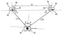
図1を参照して、本実施の形態に係る位置検出システムは、レーザを発信する発信装置20と、発信装置20とは離隔して設けられた受信装置30とを含み、これらの発信装置20および受信装置30を用いて、反射体42を備えた移動体40の位置を検出する。具体的には、発信装置20と移動体40(反射体42)との方位角αと、受信装置30と移動体40(反射体42)との方位角βを検出し、これらの方位角と、発信装置20と受信装置30との距離Dとから、発信装置20と移動体40(反射体42)との距離L(1)と、受信装置30と移動体40(反射体42)との距離L(2)を算出する。<First Embodiment>
Referring to FIG. 1, the position detection system according to the present embodiment includes a transmitting
ここで、発信装置20と移動体40(反射体42)との距離L(1)は、三角測量を用いて、L(1)=D・sinβ/sin(α+β)となる。また、受信装置30と移動体40(反射体42)との距離L(2)は、L(2)=D・sinα/sin(α+β)となる。 Here, the distance L (1) between the transmitting
発信装置20は、遮蔽板22とレーザ発信機50と、ハロゲン光受信機60とを含む。レーザ発信機50は、指向性の波動であるレーザを移動体40の反射体42に対して発信する。ハロゲン光受信機60は、無指向性の波動であるハロゲン光の反射光を受信する。遮蔽版22は、ハロゲン光受信機60が、ハロゲン光の反射光のみを受信するように、ハロゲン光の直接光を遮蔽する。 The
受信装置30は、遮蔽板32と、レーザ受信機70と、ハロゲン光発信機80とを含む。レーザ受信機70は、移動体40の反射体42により反射されたレーザの反射光を受信する。ハロゲン光発信機80は、無指向性のハロゲン光を発信する。遮蔽版32は、レーザ受信機70がレーザの反射光のみを受信するように、レーザの直接光を遮蔽する。 The receiving
本実施の形態に係る位置検出システムにおいては、まず、一次検出として、ハロゲン光発信機80から無指向性のハロゲン光を発信し、その反射光をハロゲン光受信機60で受信することで、ハロゲン光を受信する方位角α(X)を検出する。次に、二次検出として、方位角α(X)と同じ角度でレーザ発信機50からレーザを発信して、レーザを発信する方位角α(Y)を検出する。また、レーザの反射光をレーザ受信機70が受信し、レーザを受信する方位角βを検出する。このようにして、一次検出として、無指向性のハロゲン光を用いることで、移動体40の位置がわからない場合でも、発信装置20と移動体30との方位角α(X)を検出することができる。しかしながら、検出される方位角α(X)は、反射光を受信して検出されているため、ハロゲン光が空間を進む際に生じる誤差を含んだものとなっている。そこで、二次検出として、レーザを発信し、レーザを発信する方位角α(Y)と、レーザを受信する方位角βを検出する。このとき、方位角βは、反射光を受信して検出されているため、空間を進んできたレーザを受信する際に生じる誤差を含むが、方位角α(Y)は、レーザを受信せずに検出されているため、空間を進んできたレーザを受信する際に生じる誤差を含まない。本実施の形態に係る位置検出システムにおいては、移動体40の位置を検出する際には、方位角α(Y)を用いる。 In the position detection system according to the present embodiment, first, as primary detection, non-directional halogen light is transmitted from the
なお、本実施の形態においては、指向性の波動としてレーザが用いられており、無指向性の波動としてハロゲン光が用いられているが、これらの代わりに、その他、音波、超音波、電磁波などであってもよい。また、無指向性の波動を発信するものは、一般的な蛍光灯や電球であってもかまわない。 In this embodiment, a laser is used as a directional wave, and halogen light is used as a non-directional wave. However, in place of these, a sound wave, an ultrasonic wave, an electromagnetic wave, etc. It may be. Moreover, what transmits a non-directional wave may be a general fluorescent lamp or a light bulb.
図2を参照して、発信装置20および受信装置30についてさらに説明する。発信装置20は、制御部24と、メモリ26と、電源部28と、送受信部29とを含む。制御部24は、レーザ発信機50およびハロゲン光受信機60に接続され、これらの作動を制御する。メモリ26には、発信装置20が実行するプログラム、発信装置20と受信装置30との距離Dなどが記憶されている。送受信部29は、移動体40に関する検出結果および算出結果の情報を受信装置30との間で送受信する。 With reference to FIG. 2, the
受信装置30は、制御部34と、メモリ36と、電源部38と、送受信部39とを含む。制御部34は、レーザ受信機70とハロゲン光発信機80とに接続され、これらの作動を制御する。メモリ36には、受信装置30が実行するプログラム、発信装置20と受信装置30との距離Dなどが記憶されている。送受信部39は、移動体40に関する検出結果および算出結果の情報を発信装置20との間で送受信する。 The receiving
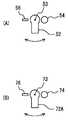
図3を参照して、レーザ発信機50と、ハロゲン光受信機60と、レーザ受信機70と、ハロゲン光発信機80とについてさらに説明する。図3(A)に示すように、レーザ発信機50は、レーザを発信するレーザ発信部52を含む。ハロゲン光受信機60は、ハロゲン光を受信する4つのハロゲン光受信部62A、62B、62C、62Dを含む。各ハロゲン光受信部は、各ハロゲン光受信部がハロゲン光の反射光を受信する方位角を平均した方位角と、レーザ発信部52(発信装置20)と移動体40との方位角αとが一致するように、レーザ発信部52を囲んだアレイ状(格子状)に配置されている。なお、各ハロゲン光受信部の配置位置は、その他、レーザ発信部52を中心とした点対称や線対称であってもよい。 The
図3(B)に示すように、レーザ受信機70は、レーザ光の反射光を受信する4つのレーザ受信部72A、72B、72C、72Dを含む。ハロゲン光発信機80は、ハロゲン光を発信するハロゲン光発信部82を含む。各レーザ受信部は、各レーザ受信部がレーザ光の反射光を受信する方位角を平均した方位角と、ハロゲン光発信部82(受信装置30)と移動体40との方位角βとが一致するように、ハロゲン光発信部82を囲んだアレイ状(格子状)に配置されている。なお、各レーザ受信部の配置位置は、その他、ハロゲン光発信部82を中心とした点対称や線対称であってもよい。 As shown in FIG. 3B, the
本実施の形態における位置検出システムにおいては、各ハロゲン光受信部がハロゲン光の反射光を受信する方位角を平均した方位角を、上述した一次検出にて検出される方位角α(X)として用いる。また、各レーザ受信部がレーザ光の反射光を受信する方位角を平均した方位角を、上述した二次検出にて検出される方位角βとして用いる。すなわち、一次検出でハロゲン光発信部82から発信されたハロゲン光は、反射体42で反射し、レーザ発信部52および各ハロゲン受信部に入射する。このとき、ハロゲン光の反射光がレーザ発信部52に入射する方位角α(X)は、各ハロゲン光受信部がハロゲン光の反射光を受信する方位角を平均した方位角として検出することできる。この方位角α(X)と同一の方位角でレーザを発信すれば、レーザは、ハロゲン光と同じ光路を逆に進み、反射体42で反射して、反射光はハロゲン光発信部82および各レーザ受信部に入射することになる。これらのうち、ハロゲン光発信部82にレーザの反射光が入射する方位角βは、各レーザ受信部がレーザ光の反射光を受信する方位角を平均した方位角として検出することができる。このようにして方位角α(X)および方位角βを検出することにより、レーザ発信器50とハロゲン光受信機60とが同一の位置に配置されているとみなすことができ、レーザ受信機70と、ハロゲン光発信機80とが同一の位置に配置されているとみなすことができる。 In the position detection system in the present embodiment, the azimuth angle obtained by averaging the azimuth angles at which each halogen light receiving unit receives the reflected light of the halogen light is defined as the azimuth angle α (X) detected by the primary detection described above. Use. Further, the azimuth angle obtained by averaging the azimuth angles at which each laser receiving unit receives the reflected light of the laser beam is used as the azimuth angle β detected by the secondary detection described above. That is, the halogen light transmitted from the
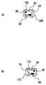
図4を参照して、レーザ発信部52およびレーザ受信部72Aについて詳細に説明する。なお、レーザ受信部72A以外の各レーザ受信部、および各ハロゲン光受信部の構造については、レーザ受信部72Aと同一であるため、ここではその詳細な説明は繰返さない。The
図4(A)に示すように、レーザ発信部52は、回動軸53を中心に回動自在に枢支されており、所望の方向にレーザを発信するように、モータ54により回動させられる。レーザ発信機50の角度は、角度センサ56により検出される。この角度センサ56により検出された角度が、発信装置20と移動体40との方位角α(Y)となる。 As shown in FIG. 4A, the
図4(B)に示すように、レーザ受信部72Aは、回動軸73により回動自在であるように枢支されており、反射体42で反射されたレーザを受信するように、モータ74により、回動される。レーザ受信部72の角度は、角度センサ76により検出される。各レーザ受信部の角度センサにより検出された角度の平均角度が、受信装置30と移動体40との方位角βとなる。なお、各ハロゲン光受信部で検出された角度の平均角度が、発信装置20と移動体40との方位角α(X)となる。 As shown in FIG. 4B, the
図5を参照して、移動体40について説明する。移動体40を側方から見た側面図を図5(A)に示す。また移動体40を上方から見た平面図を図5(B)に示す。移動体40は、レーザおよびハロゲン光を反射する5つの反射体を含む。各反射体はそれぞれ、移動体40の前後面、両側面、および上面に設けられている。これらの各反射体は、球面の一部で構成されており、一定の曲率を有する。移動体40の下面には車輪44が設けられている。移動体40はこの車輪44により、任意の場所に移動することができる。 The moving
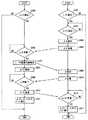
図6を参照して、本実施の形態に係る位置検出システムの発信装置20および受信装置30において実行されるプログラムの制御構造について説明する。 With reference to FIG. 6, a control structure of a program executed in transmitting
ステップ(以下、ステップをSと略す)100にて、発信装置20は、ハロゲン光の反射光を受信しているか否かを判別する。ハロゲン光の反射光を受信している場合は、処理はS102に移される。そうでない場合は、S100に戻り、ハロゲン光の反射光を受信するまでS100を繰返す。 In step (hereinafter, step is abbreviated as S) 100,
S102にて、発信装置20は、ハロゲン光の反射光を受信する方位角α(X)を検出する。S104にて、発信装置20は、ハロゲン光の反射光を受信した方位角α(X)と同じ角度で、レーザを発信する。S106にて、発信装置20は、レーザを発信する方位角α(Y)を検出する。 In S102, transmitting
S108にて、発信装置20は、受信装置30がレーザの反射光を受信する方位角βに関する情報を受信したか否かを判別する。方位角βに関する情報を受信した場合、処理はS110に移される。そうでない場合、S108に戻され、方位角βに関する情報を受信するまでS108を繰返す。 In S108, transmitting
S110にて、発信装置20は、レーザを発信する方位角α(Y)に関する情報を受信装置30に対して送信する。S112にて、発信装置20は、方位角α(Y)と、方位角βと、発信装置20と受信装置30との距離Dとから発信装置20と移動体40との距離L(1)を算出する。 In S110,
S200にて、受信装置30は、レーザの反射光を受信しているか否かを判別する。レーザの反射光を受信している場合は、処理はS208に移される。そうでない場合、処理はS202に移される。 In S200, receiving
S202にて、受信装置30は、ハロゲン光を発信する。S204にて、受信装置30は、レーザの反射光を受信したか否かを判別する。レーザの反射光を受信した場合は、処理はS206に移される。そうでない場合は、処理はS204に戻され、レーザの反射光を受信するまでS204を繰返す。 In S202, receiving
S206にて、受信装置30は、ハロゲン光の発信を停止する。S208にて、受信装置30は、レーザの反射光を受信する方位角βを検出する。S210にて、受信装置30は、方位角βに関する情報を受信装置30に対して送信する。 In S206, receiving
S212にて、受信装置30は、発信装置20からレーザを発信する方位角α(Y)に関する情報を受信したか否かを判別する。方位角α(Y)に関する情報を受信した場合は、処理はS214に移される。そうでない場合は、処理はS212に戻され、方位角α(Y)に関する情報を受信するまでS212を繰返す。 In S212, receiving
S214にて、受信装置30は、方位角α(Y)と、方位角βと、発信装置20と受信装置70との距離Dとから、受信装置70と移動体40との距離L(2)を算出する。 In S214, receiving
以上のような構造およびフローチャートに基づく、本実施の形態に係る位置検出システムの動作について説明する。 An operation of the position detection system according to the present embodiment based on the above-described structure and flowchart will be described.
現在、受信装置30はレーザの反射光を受信しておらず、移動体40の位置が検出されていないと想定する。受信装置30は、レーザの反射光を受信していないため(S200にてNO)、一次検出のため、ハロゲン光を発信する(S202)。 Currently, it is assumed that the receiving
発信装置20は、ハロゲン光を受信すると(S100にてYES)、ハロゲン光の反射光を受信する方位角α(X)を検出し(S102)、方位角α(X)と同じ角度でレーザを発信するとともに(S104)、レーザを発信する方位角α(Y)を検出する(S106)。 When receiving the halogen light (YES in S100), the transmitting
受信装置30は、レーザの反射光を受信すると(S204にてYES)、ハロゲン光の発信を停止し(S206)、レーザの反射光を受信する方位角βを検出するとともに(S208)、方位角βに関する情報を受信装置30に対して送信する(S210)。 Receiving
発信装置20は、方位角βに関する情報を受信すると(S108にてYES)、方位角α(Y)に関する情報を受信装置30に対して送信する(S110)。また、発信装置20は、方位角α(Y)と、方位角βと、発信装置20と受信装置30との距離Dとから発信装置20と移動体40との距離L(1)を算出する(S112)。 When transmitting
受信装置30は、発信装置20から方位角α(Y)に関する情報を受信すると(S212にてYES)、方位角α(Y)と、方位角βと、発信装置20と受信装置70との距離Dとから、受信装置70と移動体40との距離L(2)を算出する。 When receiving
以上のように、本実施の形態に係る位置検出システムにおいては、まず、一次検出として、無指向性のハロゲン光を発信し、その反射光を受信することで、発信装置と移動体との方位角を検出する。次に、二次検出として、一次検出で検出した方位角と同じ角度でレーザを発信して、レーザを発信する角度から、発信装置と移動体との方位角を検出し、レーザを受信する角度から、受信装置と移動体との方位角を検出する。発信装置と移動体との距離、および受信装置と移動体との距離を算出する際は、二次検出で検出された各方位角を用いている。これにより、移動体の位置がわからない場合でも、一次検出により、発信装置と移動体との方位角を検出することができる。また、二次検出により、発信装置と移動体との方位角および受信装置と移動体との方位角を検出し、それぞれの距離を算出することができる。このとき、発信装置と移動体との方位角は、レーザを発信する角度から検出するため、二次検出で検出される発信装置と移動体との方位角は、空間を進んできたレーザを受信する際に生じる誤差を含まない。そのため、移動体の位置を精度よく検出することができる。 As described above, in the position detection system according to the present embodiment, first, as primary detection, omnidirectional halogen light is transmitted, and the reflected light is received, whereby the orientation of the transmission device and the moving body is determined. Detect corners. Next, as the secondary detection, the laser beam is transmitted at the same angle as the azimuth angle detected by the primary detection, and the azimuth angle between the transmitter and the moving body is detected from the angle at which the laser beam is transmitted, and the angle at which the laser is received. Then, the azimuth angle between the receiving device and the moving body is detected. When calculating the distance between the transmitting device and the moving body and the distance between the receiving device and the moving body, each azimuth angle detected by the secondary detection is used. Thereby, even when the position of the moving body is unknown, the azimuth angle between the transmitting device and the moving body can be detected by primary detection. Further, by the secondary detection, the azimuth angle between the transmitting device and the moving body and the azimuth angle between the receiving device and the moving body can be detected, and the respective distances can be calculated. At this time, since the azimuth angle between the transmitting device and the moving body is detected from the angle at which the laser is transmitted, the azimuth angle between the transmitting device and the moving body detected by the secondary detection is received by the laser that has traveled through the space. Does not include errors that occur when Therefore, the position of the moving body can be detected with high accuracy.
<第2の実施の形態>
本実施の形態に係る位置検出システムは、前述の第1の実施の形態に係る位置検出システムの機能に加えて、移動体40の移動に応じてレーザを発信する方向を変更し、移動体40を追跡してその位置を検出する機能を備える。その他のハードウエア構成、処理フローについては、前述の第1の実施の形態に係る位置検出システムと同じである。それらの機能についても同じである。したがって、それらについての詳細な説明はここでは繰返さない。<Second Embodiment>
In addition to the function of the position detection system according to the first embodiment described above, the position detection system according to the present embodiment changes the direction in which the laser is emitted according to the movement of the
図7および図8を参照して、移動体40を追跡する方法について説明する。図7に示すように、移動体40が移動し、反射体42が、図中の矢印の方向にδ(X)だけ移動したとする。この移動に伴い、レーザの反射光がレーザ受信機70に対して入射する位置は、R(1)からR(2)にδ(Y)だけ移動する。このときのレーザの反射体42に対する入射角の変化量をΔθとすると、レーザの反射光がレーザ受信機70に向かう角度は、2Δθだけ変化する(方位角βの変化量が2Δθとなる)。なお、δ(Y)を検出するには、図3に示すように、レーザ受信部をアレイ状(格子状)に複数配置し、それらのうちレーザの反射光が入射するレーザ受信部を検出し、移動前にレーザが入射していたレーザ受信部と、移動後にレーザが入射するレーザ受信部との距離から検出したり、複数の受光部の受光量変化を比較して移動量を割出したりすればよく、その他、一般的な技術を利用すればよい。したがって、ここではその詳細な説明は繰返さない。 A method for tracking the moving
図8に、反射体42の表面の拡大図を示す。移動前に、レーザ発信機50から発信されたレーザは、Pの方向から反射体42の表面Q(1)に入射角θ(X)で入射し、レーザ受信機70のある方向R(1)に向かって反射していたと想定する。ここで、反射体42がδ(X)だけ移動すると、レーザ発信機50から発信されたレーザは、Pの方向から反射体42の表面Q(2)に入射角θ(Y)で入射し、R(2)の方向に向かって反射することになる。 FIG. 8 shows an enlarged view of the surface of the
反射体42の曲率半径をrとすると、δ(X)≪rであるため、Δθ=θ(Y)−θ(X)≒δ(X)/rとなる。その結果、レーザ受信機70に到達するレーザの反射光の位置の変化量δ(Y)は、移動体40(反射体42)とレーザ受信機70との距離をLとし、その変化量が無視できるほど微小(Lが一定)であるとすると、δ(Y)≒L・2Δθ≒2δ(X)・L/rとなる。また、Δθ≒δ(Y)/2Lである。 Assuming that the radius of curvature of the
本実施の形態に係る位置検出システムにおいては、受信装置30がδ(Y)を検出し、検出したδ(Y)からΔθを算出する。算出されたΔθに関する情報は、発信装置20に送信され、発信装置20は、レーザを発信する角度をΔθだけ補正する。このような動作を連続して行なうことにより、移動体を追跡し、常にその位置を把握することができる。このとき、δ(Y)はδ(X)をL/r倍したものであり、通常L≫rであるため、移動体40の移動量を直接測定するよりも、大きな移動量で、反射光の移動量δ(Y)を捉えることができる。そのため、移動体40の微少な移動も捉えることができ、より高精度で移動体の追跡を行なうことができる。このとき、δ(Y)のδ(X)に対する拡大率(L/r)は、反射体の曲率半径rを設定することで、任意のものとすることができる。このとき、反射体が球面や円筒面の一部で構成すれば、反射体の直径や全長などの寸法を変えることなく、曲率半径を任意なものに設定することができ、拡大率(L/r)を任意に設定することができる。 In the position detection system according to the present embodiment, receiving
図9を参照して、本実施の形態に係る位置検出システムにおける発信装置20および受信装置30が、移動体40を追跡してその位置を検出する際に実行するプログラムの制御構造について説明する。なお、本実施の形態に係る位置検出システムおいては、前述の第1の実施の形態に係る位置検出システムにおいて実行されるプログラムに加えて、以下に説明するプログラムが実行される。したがって、その他のプログラムについての説明は、ここでは繰返さない。 With reference to FIG. 9, a control structure of a program executed when transmitting
S300にて、発信装置20は、発信装置20と移動体40との距離L(1)が算出されたか否かを判別する。距離L(1)が算出されている場合は、処理はS302に移される。そうでない場合は、この処理は終了する。 In S300,
S302にて、発信装置20は、受信装置30より、Δθに関する情報を受信したか否かを判別する。Δθに関する情報を受信した場合は、処理はS304に移される。そうでない場合は、処理はS302に戻され、Δθに関する情報を受信するまでS302を繰返す。 In S302,
S304にて、発信装置20は、レーザを発信する方向をΔθだけ修正する。S306にて、発信装置20は、レーザを発信する方位角α(Y)を検出する。S308にて、発信装置20は、受信装置30よりレーザの反射光を受信する方位角βに関する情報を受信したか否かを判別する。方位角βに関する情報を受信した場合は、処理はS310に移される。そうでいな場合は、処理はS308に戻され、方位角βに関する情報を受信するまでS308を繰返す。 In S304,
S310にて、発信装置20は、レーザを発信する方位角α(Y)を受信装置30に対して送信する。S312にて、発信装置20は、方位角α(Y)と、方位角βと、発信装置20と受信装置30との距離Dとから発信装置20と移動体40との距離L(1)を算出する。 In S310, transmitting
S400にて、受信装置30は、受信装置30と移動体40との距離L(2)が算出されているか否かを判別する。L(2)が算出されている場合は、処理はS402に移される。そうでない場合は、この処理は終了する。 In S400, receiving
S402にて、受信装置30は、レーザの反射光の移動量δ(Y)を検出したか否かを判別する。δ(Y)が検出されている場合は、処理はS404に移される。そうでない場合は、処理はS402に戻され、δ(Y)を検出するまでS402を繰返す。 In S402, receiving
S404にて、受信装置30は、Δθを算出する。S406にて、受信装置30は、Δθに関する情報を発信装置20に対して送信する。S408にて、受信装置30は、レーザの反射光を受信する方位角βを検出する。S410にて、受信装置30は、レーザ反射光の方位角βを発信装置20に対して送信する。 In S404, receiving
S412にて、受信装置30は、発信装置20からレーザを発信する方位角α(Y)を受信したか否かを判別する。方位角α(Y)を受信した場合は、処理はS414に移される。そうでない場合は、処理はS412に戻され、方位角α(Y)を受信するまでS412を繰返す。 In S412, receiving
S414にて、受信装置30は、方位角α(Y)と、方位角βと、発信装置20と受信装置30との距離Dとから受信装置30と移動体40との距離L(2)を算出する。 In S414, receiving
以上のような構造およびフローチャートに基づく、本実施の形態に係る位置検出システムの動作について説明する。 An operation of the position detection system according to the present embodiment based on the above-described structure and flowchart will be described.
受信装置30は、受信装置30と移動体40との距離L(2)を算出すると(S400にてYES)、レーザの反射光の移動量δ(Y)を検出したか否かを判別する(S402)。移動量δ(Y)を検出すると(S402にてYES)、Δθを算出し(S404)、Δθに関する情報を発信装置20に対して送信する(S406)。 Receiving
発信装置20は、発信装置20と移動体40との距離L(1)を算出し(S300にてYES)、Δθに関する情報を受信すると(S302)、Δθだけレーザを発信する方向を修正し(S304)、レーザを発信する方位角α(Y)を検出する(S306)。 Transmitting
受信装置30は、修正されたレーザの反射光を受信する方位角βを検出し(S408)、レーザの反射光の方位角βに関する情報を発信装置20に対して送信する(S410)。 The receiving
発信装置20は、方位角βに関する情報を受信すると(S308にてYES)、レーザを発信する方位角α(Y)に関する情報を受信装置30に対して送信し(S310)、方位角α(Y)と、方位角βと、発信装置20と受信装置30との距離Dとから発信装置20と移動体40との距離L(1)を算出する(S312)。 When transmitting
受信装置30は、レーザを発信する方位角α(Y)に関する情報を受信すると(S412)、方位角α(Y)と、方位角βと、発信装置20と受信装置30との距離Dとから受信装置30と移動体40との距離L(2)を算出する(S414)。 When receiving information related to the azimuth angle α (Y) for transmitting the laser (S412), the receiving
以上のように、本実施の形態に係る位置検出システムは、移動体の移動に応じてレーザを発信する方向を変更する。これにより、移動体の位置が変化しても、波動を発信する方向を変更して、移動体を追跡し、その位置を検出することができる。 As described above, the position detection system according to the present embodiment changes the direction in which the laser is emitted according to the movement of the moving body. Thereby, even if the position of a moving body changes, the direction which transmits a wave can be changed, a moving body can be tracked, and the position can be detected.
<第3の実施の形態>
図10を参照して、本実施の形態に係る位置検出システムにおける発信装置20および受信装置30は、遮蔽板の代わりに、それぞれ偏光フィルタ24および偏光フィルタ34を備えている。その他のハードウェア構成および処理フローについては前述の第1または第2の実施の形態に係る位置検出システムと同じである。それらの機能についても同じである。したがってここではその詳細な説明を繰返さない。<Third Embodiment>
Referring to FIG. 10, transmitting
反射光では、反射面に垂直な偏光の割合が増えるため、レーザの直接光と反射光とでは、直線偏光の角度が変わる。また、ハロゲン光の直接光には通常偏光がないが、反射光は偏光を持って射出される。したがって、偏光フィルタ24および偏光フィルタ34を介してレーザまたはハロゲン光を受信することで、受信している光が直接光か反射光かを判別することができる。 In the reflected light, the proportion of polarized light perpendicular to the reflecting surface increases, so the angle of linearly polarized light changes between the direct laser light and the reflected light. In addition, the direct light of the halogen light usually has no polarization, but the reflected light is emitted with polarization. Therefore, by receiving laser or halogen light via the
<第4の実施の形態>
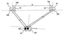
図11を参照して、本実施の形態に係る位置検出システムにおける発信装置20は第1レーザ発信機50Aと第2レーザ発信機50Bとを含む。受信装置30は、第1レーザ受信機70Aと第2レーザ受信機70Bとを含む。移動体40には、第1反射体42Fと第2反射体42Gとが設けられている。第1レーザ発信機50Aは、第1反射体42Fに対してレーザを発信し、その反射光を、第1レーザ受信機70Aが受信する。第2レーザ発信機50Bは、第2反射体42Gに対してレーザを発信し、その反射光を、第2レーザ受信機70Bが受信する。発信装置20および受信装置30は、前述の第1または第2の実施の形態と同様にして、各反射体の位置を検出する。<Fourth embodiment>
Referring to FIG. 11,
その他のハードウエア構成および処理フローについては前述の第1または第2の実施の形態に係る位置検出システムと同じである。それらの機能についても同じである。したがって、ここではその詳細な説明を繰返さない。 Other hardware configurations and processing flows are the same as those of the position detection system according to the first or second embodiment described above. The same applies to their functions. Therefore, detailed description thereof will not be repeated here.
以上のように、本実施の形態に係る位置検出システムは、複数の反射体のそれぞれに対して個別にレーザを発信し、各反射体で反射した反射光をそれぞれ個別に受信する。これにより、移動体の位置は変化せず、回転移動した場合であっても、各反射体の位置は変化するため、移動体の回転移動を検出することができる。 As described above, the position detection system according to the present embodiment individually transmits a laser to each of the plurality of reflectors and individually receives the reflected light reflected by each reflector. As a result, the position of each moving body does not change, and the position of each reflector changes even when the moving body rotates, so that the rotating movement of the moving body can be detected.
<第5の実施の形態>
図12を参照して、本実施の形態に係る位置検出システムは、発信装置20と受信装置30とを連結するとともに回動可能に設けられた回動装置90とを含む。その他のハードウエア構成および処理フローについては前述の第1または第2の実施の形態に係る位置検出システムと同じである。それらの機能についても同じである。したがって、ここではその詳細な説明を繰返さない。<Fifth embodiment>
Referring to FIG. 12, the position detection system according to the present embodiment includes a
以上のように、本実施の形態に係る位置検出システムは、回動装置90により、発信装置20と受信装置30の位置および向きを変えることができる。これにより、移動体の移動量が大きいような場合、あるいは、移動体、発信装置、受信装置が直線状に並んでしまうような場合でも、発信装置および受信装置の位置および向きを変えて、移動体の位置を検出することができる。 As described above, the position detection system according to the present embodiment can change the positions and orientations of the
<第6の実施の形態>
図13を参照して、本実施の形態に係る位置検出システムにおいて、発信装置20第1移動装置100に搭載されている。受信装置30は第2移動装置110に搭載されている。また、発信装置20はGPS(Global Positioning System)装置26を、受信装置30はGPS装置36を含む。発信装置20はGPS装置26により、発信装置20の位置を検出し、その位置に関する情報を受信装置30に送信する。同様に、受信装置30は、GPS装置36により、自己の位置を検出し、その位置に関する情報を発信装置20に送信する。また、発信装置20は、発信装置20の位置と受信装置30の位置とから、発信装置20と受信装置30との距離を算出する。同様に受信装置30は、受信装置30の位置と発信装置20の位置とから、受信装置30と発信装置20との距離を算出する。第1移動装置100は車輪102により任意の位置に移動可能である。同様に、第2移動装置110は車輪112により任意の位置に移動可能である。<Sixth Embodiment>
Referring to FIG. 13, in position detection system according to the present embodiment,
その他のハードウエア構成および処理フローについては前述の第1または第2の実施の形態に係る位置検出システムと同じである。それらの機能についても同じである。したがって、ここではその詳細な説明を繰返さない。また、GPSを用いた位置の検出方法、および発信装置20と受信装置30との距離の算出方法については、一般的な技術を利用すればよいため、ここではその詳細な説明は繰返さない。 Other hardware configurations and processing flows are the same as those of the position detection system according to the first or second embodiment described above. The same applies to their functions. Therefore, detailed description thereof will not be repeated here. In addition, since a general technique may be used for a position detection method using GPS and a calculation method of the distance between
以上のように、本実施の形態に係る位置検出システムにおいて、発信装置および受信装置のそれぞれは、第1移動装置と第2移動装置のそれぞれに搭載されている。これにより、移動体がどのように移動しても追跡し、その位置を検出することができる。 As described above, in the position detection system according to the present embodiment, each of the transmission device and the reception device is mounted on each of the first mobile device and the second mobile device. Thereby, it is possible to track and detect the position of the moving body regardless of how the moving body moves.
また、互いに自己の位置に関する情報を送受信するため、他方の位置を考慮して移動することができる。 In addition, since information about their own positions is transmitted and received, it is possible to move in consideration of the other position.
<第7の実施の形態>
図14を参照して、本実施の形態に係る位置検出システムにおいては、発信装置20および受信装置30のそれぞれは、第1羽ばたきロボット120および第2羽ばたきロボット130にそれぞれ搭載されている。第1羽ばたきロボット120は、羽部122とアクチュエータ124とを含み、羽部122をアクチュエータ124により上下に搖動することで、空間を3次元的に移動可能である。同様に、第2羽ばたきロボット130は、羽部132とアクチュエータ134とを含み、羽部132をアクチュエータ134により上下に搖動することで、空間を3次元的に移動可能である。<Seventh embodiment>
Referring to FIG. 14, in position detection system according to the present embodiment, transmitting
その他のハードウエア構成および処理フローについては前述の第6の実施の形態に係る位置検出システムと同じである。それらの機能についても同じである。したがって、ここではその詳細な説明を繰返さない。 Other hardware configurations and processing flows are the same as those of the position detection system according to the sixth embodiment described above. The same applies to their functions. Therefore, detailed description thereof will not be repeated here.
以上のように、本実施の形態に係る位置検出システムにおいては、発信装置20および受信装置30のそれぞれは、第1羽ばたきロボット120および第2羽ばたきロボット130にそれぞれ搭載されている。これにより、移動体がどのような位置に移動しても、3次元的に移動し、追跡することができる。 As described above, in the position detection system according to the present embodiment, transmitting
<第8の実施の形態>
図15を参照して、本実施の形態に係る位置検出システムにおいては、発信装置20はハロゲン光受信機を備えておらず、レーザ発信機50により、レーザをS(1)の方向からS(2)の方向に掃引する。受信装置30は、ハロゲン光発信機を備えていない。その他のハードウエア構成については、前述の第1または第2の実施の形態と同じである。また、処理フローについては、ハロゲン光の送受信に関するもの以外は、前述の第1または第2の実施の形態と同じである。それらの機能についても同じである。したがって、ここではその詳細な説明は繰返さない。<Eighth Embodiment>
Referring to FIG. 15, in the position detection system according to the present embodiment, transmitting
以上のように、本実施の形態に係る位置検出システムの発信装置は、レーザを予め定められた範囲で掃引する。これにより、位置が検出されていない移動体を探索することができる。 As described above, the transmission device of the position detection system according to the present embodiment sweeps the laser within a predetermined range. Thereby, it is possible to search for a moving body whose position is not detected.
<その他の実施の形態>
図16を参照して、その他の実施の形態について説明する。なお、以下に説明する実施の形態においては、移動体40に設けられた反射体の形状が、前述の第1ないし第7のいずれかの実施の形態における移動体40に設けられた反射体の形状と異なる。その他のハードウエア構成および処理フローについては、前述の第1ないし第7の実施の形態にかかる位置検出システムと同じである。それらの機能についても同じである。したがって、ここではその詳細な説明を繰返さない。<Other embodiments>
With reference to FIG. 16, another embodiment will be described. In the embodiment described below, the shape of the reflector provided on the moving
図16(A)を参照して、本実施の形態に係る位置検出システムにより位置が検出される移動体は、球状の反射体45A〜45Eを含む。これにより、移動体の影にならない限り、どのような方向からでも同じように、レーザまたはハロゲン光を反射することができる。Referring to FIG. 16A, the moving body whose position is detected by the position detection system according to the present embodiment includes
図16(B)を参照して、本実施の形態に係る位置検出システムにより位置が検出される移動体40は、表面が円筒状である反射体46Aおよび円筒の凸面の一部である反射体46B〜46Eを含む。これにより、移動体が平面を移動するだけのような場合に、反射体の構成を簡素化することができる。なお、円筒の凹面の一部を用いて反射体を構成してもよい。Referring to FIG. 16B, a moving
図16(C)を参照して、本実施の形態に係る位置検出システムにより位置が検出される移動体40は、表面が放物線状の凹面である反射体47を含む。これにより、反射体の表面の曲率が、反射体の部位によって変化することになる。そのため、たとえば、移動体の移動量が一定であれば、受信装置で検出される移動量の変化から、その反射体のどの部位で反射しているか(反射点)を検出できる。その結果、移動体の中心位置など、反射体との相対位置既知の部位の位置を検出することができる。なお、放物線状の凹面や凸面の一部を用いて反射体を構成してもよい。 Referring to FIG. 16C, moving
図16(D)を参照して、本実施の形態に係る位置検出システムにより位置が検出される移動体40は、表面が楕円状である反射体48Aおよび楕円の凸面の一部である反射体48B〜48Eを含む。これにより、これにより、反射体の表面の曲率が、反射体の部位によって変化することになる。そのため、たとえば、移動体の移動量が一定であれば、受信装置で検出される移動量の変化から、その反射体のどの部位で反射しているか(反射点)を検出できる。その結果、移動体の中心位置など、反射体との相対位置既知の部位の位置を検出することができる。なお、楕円の凹面の一部を用いて反射体を構成してもよい。 Referring to FIG. 16D, a moving
今回開示された実施の形態はすべての点で例示であって制限的なものではないと考えられるべきである。本発明の範囲は上記した説明ではなくて特許請求の範囲によって示され、特許請求の範囲と均等の意味および範囲内でのすべての変更が含まれることが意図される。 The embodiment disclosed this time should be considered as illustrative in all points and not restrictive. The scope of the present invention is defined by the terms of the claims, rather than the description above, and is intended to include any modifications within the scope and meaning equivalent to the terms of the claims.
20 発信装置、22 遮蔽版、24 偏光フィルタ、26 GPS装置、30 受信装置、32 遮蔽版、34 偏光フィルタ、36 GPS装置、40 移動体、42,42A,42B,42C,42D,42E,42F,42G,45A,45B,45C,45D,45E,46A,46B,46C,46D,46E,47,48A,48B,48C,48D,48E 反射体、50 レーザ発信機、52 レーザ発信部、53 回動軸、54 モータ、56 角度センサ、60 ハロゲン光受信機、62A,62B,62C,62D ハロゲン光受信部、70 レーザ受信機、72A,72B,72C,72D レーザ受信部、73 回動軸、74 モータ、76 角度センサ、80 ハロゲン光発信機、82 ハロゲン光発信部、90 回動装置、100,110 移動装置、120,130 羽ばたきロボット。 20 transmitting device, 22 shielding plate, 24 polarizing filter, 26 GPS device, 30 receiving device, 32 shielding plate, 34 polarizing filter, 36 GPS device, 40 moving body, 42, 42A, 42B, 42C, 42D, 42E, 42F, 42G, 45A, 45B, 45C, 45D, 45E, 46A, 46B, 46C, 46D, 46E, 47, 48A, 48B, 48C, 48D, 48E Reflector, 50 Laser transmitter, 52 Laser transmitter, 53 Rotating shaft , 54 motor, 56 angle sensor, 60 halogen light receiver, 62A, 62B, 62C, 62D halogen light receiver, 70 laser receiver, 72A, 72B, 72C, 72D laser receiver, 73 rotating shaft, 74 motor, 76 angle sensor, 80 halogen light transmitter, 82 halogen light transmitter, 90 rotating device, 00,110 mobile devices, 120 and 130 flapping robot.
Claims (22)
Translated fromJapanese前記発信装置は、
前記波動を発信するための発信手段と、
前記波動を発信する方向を検出するための手段とを含み、
前記受信装置は、
前記反射体により反射された前記波動の反射波を受信するための受信手段と、
前記反射波を受信する方向を検出するための方向検出手段とを含み、
前記発信装置と前記受信装置とは離隔して設けられ、
前記反射体は、前記移動体の移動量よりも前記受信装置に到達する波動の反射波の位置の変化量が大きくなるように波動を反射し、
前記発信装置と前記受信装置のうちの少なくともいずれか1つは、前記波動を発信する方向と、前記波動の反射波を受信する方向と、前記発信装置と前記受信装置との距離とに基づいて、前記移動体の位置を検出し、
前記受信装置は、前記受信装置に到達する波動の反射波の位置の変化量を検出するための手段をさらに含み、
前記発信装置と前記受信装置のうちの少なくともいずれか1つは前記受信装置に到達する波動の反射波の位置の変化量から前記移動体の移動量を算出するための手段をさらに含む、位置検出システム。A position detection system including a transmitting device, a receiving device, and a moving body whose position is detected using these devices, the moving body including a reflector that reflects a wave propagating in space,
The transmitting device is
A transmitting means for transmitting the wave;
Means for detecting a direction of transmitting the wave,
The receiving device is:
Receiving means for receiving a reflected wave of the wave reflected by the reflector;
Direction detecting means for detecting a direction in which the reflected wave is received;
The transmitting device and the receiving device are provided apart from each other,
The reflector reflects the wave so that the amount of change in the position of the reflected wave of the wave reaching the receiving device is larger than the amount of movement of the moving body,
At least one of the transmitting device and the receiving device is based on a direction of transmitting the wave, a direction of receiving a reflected wave of the wave, and a distance between the transmitting device and the receiving device. , Detecting the position of the moving body,
The receiving device further includes means for detecting a change amount of a position of a reflected wave of a wave reaching the receiving device,
At least one of the transmitting device and the receiving device further includes means for calculating a moving amount of the moving body from a change amount of a position of a reflected wave of a wave reaching the receiving device. system.
前記発信装置および前記受信装置のそれぞれは、検出結果に関する情報を互いに送受信するための手段をさらに含む、請求項3または4に記載の位置検出システム。The moving means includes a first moving means for changing at least one of a position and an orientation of the transmitting device, and a second moving means for changing at least one of the position and the orientation of the receiving device. And exist
5. The position detection system according to claim 3, wherein each of the transmission device and the reception device further includes means for transmitting and receiving information related to a detection result to each other.
自己の位置を検出するための手段と、
前記位置に関する情報を互いに送受信するための手段とをさらに含む、請求項3ないし5のいずれかに記載の位置検出システム。Each of the transmitter and the receiver is
Means for detecting the position of the self;
The position detection system according to claim 3, further comprising means for transmitting and receiving information on the position to each other.
前記受信手段は、指向性の波動の反射波を受信するための指向性波動受信手段を含み、
前記方向検出手段は、指向性の波動の反射波を受信する方向を検出するための指向性波動方向検出手段を含む、請求項1ないし6のいずれかに記載の位置検出システム。The transmitting means includes directional wave transmitting means for transmitting directional waves,
The receiving means includes directional wave receiving means for receiving a reflected wave of a directional wave,
7. The position detection system according to claim 1, wherein the direction detection unit includes a directional wave direction detection unit for detecting a direction in which a reflected wave of a directional wave is received.
前記発信装置は、
前記反射体で反射した前記無指向性の波動の反射波を受信するための無指向性波動受信手段と、
前記無指向性の波動の反射波を受信する方向を検出するための無指向性波動方向検出手段とをさらに含む、請求項7に記載の位置検出システム。The receiving device further includes omnidirectional wave transmitting means for transmitting omnidirectional waves,
The transmitting device is
Omnidirectional wave receiving means for receiving a reflected wave of the omnidirectional wave reflected by the reflector;
The position detection system according to claim 7, further comprising omnidirectional wave direction detection means for detecting a direction in which a reflected wave of the omnidirectional wave is received.
前記指向性波動受信手段は、指向性の波動の反射波を受信する複数の指向性波動受信部を含み、
前記指向性波動方向検出手段は、
各前記指向性波動受信部が指向性の波動の反射波を受信する方向を検出するための手段と、
各前記指向性波動受信部が指向性の波動の反射波を受信する方向を平均した第1の平均方向を検出するための手段とを含み、
前記無指向性波動発信手段は、無指向性の波動を発信する無指向性波動発信部を含み、
前記無指向性波動受信手段は、無指向性の波動の反射波を受信する複数の無指向性波動受信部を含み、
前記無指向性波動方向検出手段は、
各前記無指向性波動受信部が無指向性の波動の反射波を受信する方向を検出するための手段と、
各前記無指向性波動受信部が無指向性の波動の反射波を受信する方向を平均した第2の平均方向を検出するための手段とを含み、
各前記無指向性波動受信部は、前記第2の平均方向が、前記指向性波動発信部に対する前記反射体の方向と一致するように配置され、
各前記指向性波動受信部は、前記第1の平均方向が、前記無指向性波動発信部に対する前記反射体の方向と一致するように配置されている、請求項11に記載の位置検出システム。The directional wave transmission means includes a directional wave transmission unit that transmits directional waves,
The directional wave receiving means includes a plurality of directional wave receivers that receive reflected waves of directional waves,
The directional wave direction detecting means includes
Means for detecting a direction in which each of the directional wave receivers receives a reflected wave of a directional wave;
Means for detecting a first average direction obtained by averaging the directions in which each of the directional wave receivers receives a reflected wave of a directional wave;
The non-directional wave transmission means includes a non-directional wave transmission unit that transmits a non-directional wave,
The omnidirectional wave receiving means includes a plurality of omnidirectional wave receivers that receive reflected waves of omnidirectional waves,
The omnidirectional wave direction detecting means is
Means for detecting a direction in which each of the omnidirectional wave receivers receives a reflected wave of an omnidirectional wave;
Means for detecting a second average direction obtained by averaging the directions in which each of the omnidirectional wave receivers receives a reflected wave of the omnidirectional wave,
Each of the omnidirectional wave receivers is arranged so that the second average direction matches the direction of the reflector with respect to the directional wave transmitter,
The position detection system according to claim 11, wherein each of the directional wave receiving units is arranged such that the first average direction matches a direction of the reflector with respect to the omnidirectional wave transmitting unit.
前記受信手段には、第1の受信手段および第2の受信手段があり、
前記反射体には、第1の反射体および第2の反射体があり、
前記第1の発信手段は、前記第1の反射体に対して前記波動を発信するための手段を含み、
前記第2の発信手段は、前記第2の反射体に対して前記波動を発信するための手段を含み、
前記第1の受信手段は、前記第1の反射体で反射した反射波を受信するための手段を含み、
前記第2の受信手段は、前記第2の反射体で反射した反射波を受信するための手段を含む、請求項1ないし13のいずれかに記載の位置検出システム。The transmission means includes a first transmission means and a second transmission means,
The receiving means includes a first receiving means and a second receiving means,
The reflector includes a first reflector and a second reflector,
The first transmitting means includes means for transmitting the wave to the first reflector,
The second transmitting means includes means for transmitting the wave to the second reflector,
The first receiving means includes means for receiving a reflected wave reflected by the first reflector,
The position detection system according to claim 1, wherein the second receiving unit includes a unit for receiving a reflected wave reflected by the second reflector.
Priority Applications (2)
| Application Number | Priority Date | Filing Date | Title |
|---|---|---|---|
| JP2003297714AJP3977303B2 (en) | 2003-08-21 | 2003-08-21 | Position detection system, transmitter and receiver in position detection system |
| US10/918,018US7474256B2 (en) | 2003-08-21 | 2004-08-12 | Position detecting system, and transmitting and receiving apparatuses for the position detecting system |
Applications Claiming Priority (1)
| Application Number | Priority Date | Filing Date | Title |
|---|---|---|---|
| JP2003297714AJP3977303B2 (en) | 2003-08-21 | 2003-08-21 | Position detection system, transmitter and receiver in position detection system |
Publications (2)
| Publication Number | Publication Date |
|---|---|
| JP2005069772A JP2005069772A (en) | 2005-03-17 |
| JP3977303B2true JP3977303B2 (en) | 2007-09-19 |
Family
ID=34191189
Family Applications (1)
| Application Number | Title | Priority Date | Filing Date |
|---|---|---|---|
| JP2003297714AExpired - Fee RelatedJP3977303B2 (en) | 2003-08-21 | 2003-08-21 | Position detection system, transmitter and receiver in position detection system |
Country Status (2)
| Country | Link |
|---|---|
| US (1) | US7474256B2 (en) |
| JP (1) | JP3977303B2 (en) |
Families Citing this family (36)
| Publication number | Priority date | Publication date | Assignee | Title |
|---|---|---|---|---|
| EP2148969B1 (en)* | 2007-04-24 | 2014-01-01 | Yale Security Inc | Door closer assembly |
| US8166421B2 (en)* | 2008-01-14 | 2012-04-24 | Primesense Ltd. | Three-dimensional user interface |
| US9035876B2 (en) | 2008-01-14 | 2015-05-19 | Apple Inc. | Three-dimensional user interface session control |
| US8933876B2 (en) | 2010-12-13 | 2015-01-13 | Apple Inc. | Three dimensional user interface session control |
| WO2010119866A1 (en)* | 2009-04-13 | 2010-10-21 | 株式会社コロプラ | System and method for preventing falsification of movement distance |
| JP5645928B2 (en)* | 2009-06-19 | 2014-12-24 | コーダ ワイヤレス ピーティーワイ リミテッドCohda Wireless Pty Ltd | Environmental evaluation in wireless communication systems |
| US8787663B2 (en)* | 2010-03-01 | 2014-07-22 | Primesense Ltd. | Tracking body parts by combined color image and depth processing |
| TWI431252B (en)* | 2010-07-14 | 2014-03-21 | Pixart Imaging Inc | Distance measuring device and ranging method |
| US9201501B2 (en) | 2010-07-20 | 2015-12-01 | Apple Inc. | Adaptive projector |
| JP5791131B2 (en) | 2010-07-20 | 2015-10-07 | アップル インコーポレイテッド | Interactive reality extension for natural interactions |
| US8959013B2 (en) | 2010-09-27 | 2015-02-17 | Apple Inc. | Virtual keyboard for a non-tactile three dimensional user interface |
| JP5635870B2 (en)* | 2010-10-22 | 2014-12-03 | 新日本無線株式会社 | Position detection device using a reflective photosensor |
| US8872762B2 (en) | 2010-12-08 | 2014-10-28 | Primesense Ltd. | Three dimensional user interface cursor control |
| EP2672880B1 (en) | 2011-02-09 | 2019-05-22 | Apple Inc. | Gaze detection in a 3d mapping environment |
| US8881051B2 (en) | 2011-07-05 | 2014-11-04 | Primesense Ltd | Zoom-based gesture user interface |
| US9377865B2 (en) | 2011-07-05 | 2016-06-28 | Apple Inc. | Zoom-based gesture user interface |
| US9459758B2 (en) | 2011-07-05 | 2016-10-04 | Apple Inc. | Gesture-based interface with enhanced features |
| US9030498B2 (en) | 2011-08-15 | 2015-05-12 | Apple Inc. | Combining explicit select gestures and timeclick in a non-tactile three dimensional user interface |
| US9122311B2 (en) | 2011-08-24 | 2015-09-01 | Apple Inc. | Visual feedback for tactile and non-tactile user interfaces |
| US9218063B2 (en) | 2011-08-24 | 2015-12-22 | Apple Inc. | Sessionless pointing user interface |
| US9229534B2 (en) | 2012-02-28 | 2016-01-05 | Apple Inc. | Asymmetric mapping for tactile and non-tactile user interfaces |
| AU2013239179B2 (en) | 2012-03-26 | 2015-08-20 | Apple Inc. | Enhanced virtual touchpad and touchscreen |
| US20140046923A1 (en) | 2012-08-10 | 2014-02-13 | Microsoft Corporation | Generating queries based upon data points in a spreadsheet application |
| DE102012223924A1 (en)* | 2012-12-20 | 2014-06-26 | Hilti Aktiengesellschaft | Method and device for determining the location coordinates of a target object |
| CN104655161B (en)* | 2013-11-21 | 2017-05-10 | 科沃斯机器人股份有限公司 | Distance measuring device and method of distance measuring device to find distance measuring initial point |
| US10564116B2 (en) | 2016-04-28 | 2020-02-18 | Fluke Corporation | Optical image capture with position registration and RF in-wall composite image |
| US10209357B2 (en)* | 2016-04-28 | 2019-02-19 | Fluke Corporation | RF in-wall image registration using position indicating markers |
| US10571591B2 (en) | 2016-04-28 | 2020-02-25 | Fluke Corporation | RF in-wall image registration using optically-sensed markers |
| US10585203B2 (en) | 2016-04-28 | 2020-03-10 | Fluke Corporation | RF in-wall image visualization |
| US10254398B2 (en) | 2016-04-28 | 2019-04-09 | Fluke Corporation | Manipulation of 3-D RF imagery and on-wall marking of detected structure |
| US10302793B2 (en) | 2016-08-04 | 2019-05-28 | Fluke Corporation | Blending and display of RF in wall imagery with data from other sensors |
| US10444344B2 (en) | 2016-12-19 | 2019-10-15 | Fluke Corporation | Optical sensor-based position sensing of a radio frequency imaging device |
| US10473759B2 (en)* | 2017-03-28 | 2019-11-12 | GM Global Technology Operations LLC | Tool for automatic multiple radar calibration |
| US11796653B2 (en)* | 2018-08-02 | 2023-10-24 | Uatc, Llc | Detecting and tracking Lidar cross-talk |
| KR101936152B1 (en)* | 2018-08-28 | 2019-01-08 | 한화시스템 주식회사 | Dirctional linear array sensor and signal processing method thereof |
| CN115183962B (en)* | 2022-07-11 | 2023-03-10 | 深圳大学 | Laser measurement method and system for bridge deflection |
Family Cites Families (69)
| Publication number | Priority date | Publication date | Assignee | Title |
|---|---|---|---|---|
| US1981884A (en)* | 1933-06-13 | 1934-11-27 | Albert H Taylor | System for detecting objects by radio |
| FR806986A (en)* | 1935-06-08 | 1936-12-30 | Telefunken Gmbh | Improvements in methods for detecting the presence of an object in an electromagnetic radiation field |
| NL135042C (en)* | 1942-05-27 | |||
| US3067281A (en)* | 1945-10-01 | 1962-12-04 | Gen Electric | Underwater object locator and viewer |
| US2650359A (en)* | 1950-03-20 | 1953-08-25 | William W Brockway | Radio navigation system |
| US2982859A (en)* | 1959-02-04 | 1961-05-02 | Engelhard Hanovia Inc | Light communication alinement system |
| US3400363A (en)* | 1965-12-09 | 1968-09-03 | Pan American Petroleum Corp | Wavelet reconstruction process for sonic, seismic, and radar exploration |
| US3705261A (en)* | 1970-04-09 | 1972-12-05 | Symbionics Inc | Scanning system for yielding a three-dimensional display |
| US3846026A (en)* | 1971-11-01 | 1974-11-05 | Continental Oil Co | Rotating beam surveying method and apparatus |
| US4184767A (en)* | 1975-07-21 | 1980-01-22 | The United States Of America As Represented By The Secretary Of The Navy | Frequency agile optical radar |
| DE2914560A1 (en)* | 1978-04-14 | 1979-10-25 | Plessey Handel Investment Ag | DESTINATION ARRANGEMENT |
| DE2914547A1 (en)* | 1978-04-14 | 1979-10-18 | Plessey Handel Investment Ag | DESTINATION ARRANGEMENT |
| US5164732A (en)* | 1980-02-13 | 1992-11-17 | Eid Electronic Identification Systems Ltd. | Highway vehicle identification system with high gain antenna |
| SE450975B (en)* | 1981-08-07 | 1987-09-07 | Geotronics Ab | DEVICE FOR OPERATOR COMMUNICATION IN A SYSTEM FOR ELECTRONIC DISTANCE Saturation |
| US4568182A (en)* | 1981-12-22 | 1986-02-04 | Summagraphics Corporation | Optical system for determining the position of a cursor |
| JPS5912370A (en) | 1982-07-12 | 1984-01-23 | Kubota Ltd | How to detect the position of a moving object |
| US4550250A (en)* | 1983-11-14 | 1985-10-29 | Hei, Inc. | Cordless digital graphics input device |
| JPS60211308A (en) | 1984-04-06 | 1985-10-23 | Hitachi Ltd | Space coordinate orientation device for moving body |
| SE442557B (en)* | 1984-05-21 | 1986-01-13 | Geotronics Ab | DEVICE FOR KEEPING AN INSTRUMENT OBTAINED TO A GREAT REFLECTOR |
| US4621267A (en)* | 1984-09-28 | 1986-11-04 | The Boeing Company | Bearing intersection deghosting by altitude comparison system and methods |
| US4729660A (en)* | 1985-03-22 | 1988-03-08 | Toshihiro Tsumura | Position measuring apparatus of moving vehicle |
| US4688933A (en)* | 1985-05-10 | 1987-08-25 | The Laitram Corporation | Electro-optical position determining system |
| US20020196176A1 (en)* | 1986-06-03 | 2002-12-26 | Fullerton Larry W. | Time domain radio transmission system |
| IE59553B1 (en)* | 1986-10-30 | 1994-03-09 | Inst For Ind Res & Standards | Position sensing apparatus |
| US4820041A (en)* | 1986-11-12 | 1989-04-11 | Agtek Development Co., Inc. | Position sensing system for surveying and grading |
| US5026153A (en)* | 1989-03-01 | 1991-06-25 | Mitsubishi Denki K.K. | Vehicle tracking control for continuously detecting the distance and direction to a preceding vehicle irrespective of background dark/light distribution |
| JPH02253116A (en)* | 1989-03-27 | 1990-10-11 | Mitsubishi Electric Corp | Inter-vehicle distance detection device |
| JPH03242518A (en) | 1990-02-20 | 1991-10-29 | Nec Corp | Observing apparatus for vibration of sinking part of outside plate of hull |
| JPH03295487A (en) | 1990-04-13 | 1991-12-26 | Mitsubishi Electric Corp | Detecting method for space floating body |
| JP2986567B2 (en) | 1991-03-13 | 1999-12-06 | 松下電器産業株式会社 | Inter-vehicle distance measuring device |
| US5166668A (en)* | 1991-04-10 | 1992-11-24 | Data Stream Corporation | Wireless pen-type input device for use with a computer |
| JPH0527036A (en) | 1991-07-23 | 1993-02-05 | Fujitsu Ltd | Direction measuring device, position determining device, and position determining method |
| NO921193D0 (en)* | 1992-03-26 | 1992-03-26 | Susar As | SYSTEM FOR DETECTION, MEASUREMENT AND CLASSIFICATION OF AIR PHENOMES |
| JPH0618260A (en) | 1992-07-02 | 1994-01-25 | Omron Corp | Object observing apparatus |
| JPH0659016A (en) | 1992-08-07 | 1994-03-04 | Sanyo Electric Co Ltd | Position measuring device for moving body |
| JP3100478B2 (en)* | 1992-10-27 | 2000-10-16 | 株式会社トプコン | Laser rotary irradiation device with reciprocating laser scanning system |
| US5243397A (en)* | 1992-11-25 | 1993-09-07 | Elop-Electrooptics Industries Ltd. | Distance measuring system |
| US5264855A (en)* | 1993-02-09 | 1993-11-23 | The United States Of America As Represented By The Secretary Of The Air Force | Technique for stationary radar target discrimination |
| US5457394A (en)* | 1993-04-12 | 1995-10-10 | The Regents Of The University Of California | Impulse radar studfinder |
| US5583638A (en)* | 1993-07-21 | 1996-12-10 | Hewlett-Packard Company | Angular michelson interferometer and optical wavemeter based on a rotating periscope |
| US6553130B1 (en)* | 1993-08-11 | 2003-04-22 | Jerome H. Lemelson | Motor vehicle warning and control system and method |
| US5594413A (en)* | 1993-12-27 | 1997-01-14 | Hyundai Electronics Industries Co., Ltd. | Car collision prevention apparatus and method using dual processor and automatic sensor switching function |
| US5465094A (en)* | 1994-01-14 | 1995-11-07 | The Regents Of The University Of California | Two terminal micropower radar sensor |
| US5576627A (en)* | 1994-09-06 | 1996-11-19 | The Regents Of The University Of California | Narrow field electromagnetic sensor system and method |
| JPH0926474A (en) | 1995-07-13 | 1997-01-28 | Toshiba Corp | Radar system |
| US6373573B1 (en)* | 2000-03-13 | 2002-04-16 | Lj Laboratories L.L.C. | Apparatus for measuring optical characteristics of a substrate and pigments applied thereto |
| US5974348A (en)* | 1996-12-13 | 1999-10-26 | Rocks; James K. | System and method for performing mobile robotic work operations |
| US6459492B1 (en)* | 1997-03-14 | 2002-10-01 | Agilent Technologies, Inc. | Non-contact position sensor |
| DE19724773C2 (en)* | 1997-06-12 | 1999-05-12 | Diehl Stiftung & Co | Alarm sensor, in particular for a tracking device |
| US5976038A (en)* | 1997-12-10 | 1999-11-02 | Toy Builders | Apparatus for detecting moving ball |
| US6381055B1 (en)* | 1998-04-16 | 2002-04-30 | At&T Corp. | Transceiver positioning in free-space optical networks |
| JP2000131059A (en) | 1998-10-28 | 2000-05-12 | Omron Corp | Distance measurement method and device therefor, and start/stop control device of vehicle |
| JP2000241529A (en)* | 1999-02-22 | 2000-09-08 | Honda Motor Co Ltd | Radar apparatus and radar apparatus abnormality detection method |
| JP2000283709A (en)* | 1999-03-29 | 2000-10-13 | Ando Electric Co Ltd | Moving object position detector and optical interferometer |
| US6177903B1 (en)* | 1999-06-14 | 2001-01-23 | Time Domain Corporation | System and method for intrusion detection using a time domain radar array |
| WO2000079235A1 (en)* | 1999-06-23 | 2000-12-28 | Patrick Toomey | Water detection and source identification methods for structures using electromagnetic radiation spectroscopy |
| US6842270B2 (en)* | 1999-12-16 | 2005-01-11 | Fuji Photo Film Co., Ltd. | Image reading device |
| JP2001272226A (en)* | 2000-03-24 | 2001-10-05 | Koito Mfg Co Ltd | Location-measuring laser device |
| DE10023477C2 (en)* | 2000-05-10 | 2002-09-19 | Sentech Instr Gmbh | ellipsometer |
| WO2002023218A2 (en)* | 2000-09-14 | 2002-03-21 | Time Domain Corporation | System and method for detecting an intruder using impulse radio technology |
| JP3608001B2 (en) | 2000-12-18 | 2005-01-05 | 三菱電機株式会社 | Passive radar device |
| US6667724B2 (en)* | 2001-02-26 | 2003-12-23 | Time Domain Corporation | Impulse radar antenna array and method |
| US6492937B1 (en)* | 2001-11-02 | 2002-12-10 | Itt Manufacturing Enterprises, Inc. | High precision range measurement technique |
| JP3888672B2 (en)* | 2001-12-25 | 2007-03-07 | 株式会社小糸製作所 | Reflector movable automotive headlamp |
| JP2003242812A (en)* | 2002-02-18 | 2003-08-29 | Koito Mfg Co Ltd | Vehicle lamp |
| US6653972B1 (en)* | 2002-05-09 | 2003-11-25 | Raytheon Company | All weather precision guidance of distributed projectiles |
| US6914554B1 (en)* | 2003-10-17 | 2005-07-05 | The United States Of America As Represented By The Secretary Of The Army | Radar beam steering with remote reflectors/refractors |
| PL1619469T3 (en)* | 2004-07-22 | 2008-05-30 | Bea Sa | Light scanning device for detection around automatic doors |
| US7138938B1 (en)* | 2005-05-06 | 2006-11-21 | Ford Global Technologies, Llc | System and method for preemptively sensing an object and selectively operating both a collision countermeasure system and a parking assistance system aboard an automotive vehicle |
- 2003
- 2003-08-21JPJP2003297714Apatent/JP3977303B2/ennot_activeExpired - Fee Related
- 2004
- 2004-08-12USUS10/918,018patent/US7474256B2/ennot_activeExpired - Fee Related
Also Published As
| Publication number | Publication date |
|---|---|
| US7474256B2 (en) | 2009-01-06 |
| JP2005069772A (en) | 2005-03-17 |
| US20050043039A1 (en) | 2005-02-24 |
Similar Documents
| Publication | Publication Date | Title |
|---|---|---|
| JP3977303B2 (en) | Position detection system, transmitter and receiver in position detection system | |
| US10698094B2 (en) | 3D-position determination method and device | |
| CA2602332C (en) | Method and system for determining position and orientation of an object | |
| EP1174682B1 (en) | Position determination system | |
| US20150346319A1 (en) | Method and Device for Determining the Position Coordinates of a Target Object | |
| JP2007506109A (en) | Method and system for determining the spatial position of a portable measuring device | |
| JP7120723B2 (en) | laser scanner system | |
| WO2010108644A1 (en) | Method for optically scanning and measuring a scene | |
| JP2001334966A (en) | Trailer connecting angle detector | |
| JPH11132746A (en) | Optical deflection angle measuring device and position measuring device of underground excavator | |
| JPH05240940A (en) | Optical measuring system | |
| JPH11211812A (en) | Radar device and its clinometer error detecting method | |
| JP2005114601A (en) | Navigation device and present position calculating method | |
| JP3982959B2 (en) | Mobile body position detection equipment | |
| JPH11183174A (en) | Position measuring apparatus for mobile | |
| JP4794416B2 (en) | Target location system | |
| JP2007200045A (en) | Autonomous mobile device | |
| JP3784165B2 (en) | Mobile body position detection equipment | |
| JP7082853B2 (en) | Rangefinder, distance measurement method, thickness gauge device and thickness measurement method | |
| JP2000329848A (en) | Probing method and device thereof | |
| JP2008058096A (en) | Travel position detector | |
| JP5285974B2 (en) | measuring device | |
| EP4564050A1 (en) | Surveying system with bi-dimensional scanning profile | |
| JPH05257530A (en) | Method and device for correcting bearing and position of moving robot | |
| JPH05172516A (en) | Apparatus and method for automatically measuring position and attitude of moving body |
Legal Events
| Date | Code | Title | Description |
|---|---|---|---|
| A977 | Report on retrieval | Free format text:JAPANESE INTERMEDIATE CODE: A971007 Effective date:20060303 | |
| A131 | Notification of reasons for refusal | Free format text:JAPANESE INTERMEDIATE CODE: A131 Effective date:20060411 | |
| A521 | Written amendment | Free format text:JAPANESE INTERMEDIATE CODE: A523 Effective date:20060609 | |
| A131 | Notification of reasons for refusal | Free format text:JAPANESE INTERMEDIATE CODE: A131 Effective date:20070116 | |
| A521 | Written amendment | Free format text:JAPANESE INTERMEDIATE CODE: A523 Effective date:20070312 | |
| A131 | Notification of reasons for refusal | Free format text:JAPANESE INTERMEDIATE CODE: A131 Effective date:20070403 | |
| A521 | Written amendment | Free format text:JAPANESE INTERMEDIATE CODE: A523 Effective date:20070508 | |
| TRDD | Decision of grant or rejection written | ||
| A01 | Written decision to grant a patent or to grant a registration (utility model) | Free format text:JAPANESE INTERMEDIATE CODE: A01 Effective date:20070612 | |
| A61 | First payment of annual fees (during grant procedure) | Free format text:JAPANESE INTERMEDIATE CODE: A61 Effective date:20070620 | |
| FPAY | Renewal fee payment (event date is renewal date of database) | Free format text:PAYMENT UNTIL: 20100629 Year of fee payment:3 | |
| R150 | Certificate of patent or registration of utility model | Ref document number:3977303 Country of ref document:JP Free format text:JAPANESE INTERMEDIATE CODE: R150 Free format text:JAPANESE INTERMEDIATE CODE: R150 | |
| FPAY | Renewal fee payment (event date is renewal date of database) | Free format text:PAYMENT UNTIL: 20100629 Year of fee payment:3 | |
| FPAY | Renewal fee payment (event date is renewal date of database) | Free format text:PAYMENT UNTIL: 20110629 Year of fee payment:4 | |
| FPAY | Renewal fee payment (event date is renewal date of database) | Free format text:PAYMENT UNTIL: 20120629 Year of fee payment:5 | |
| FPAY | Renewal fee payment (event date is renewal date of database) | Free format text:PAYMENT UNTIL: 20120629 Year of fee payment:5 | |
| FPAY | Renewal fee payment (event date is renewal date of database) | Free format text:PAYMENT UNTIL: 20130629 Year of fee payment:6 | |
| LAPS | Cancellation because of no payment of annual fees |