JP3973543B2 - Reception method and apparatus - Google Patents
Reception method and apparatusDownload PDFInfo
- Publication number
- JP3973543B2 JP3973543B2JP2002337306AJP2002337306AJP3973543B2JP 3973543 B2JP3973543 B2JP 3973543B2JP 2002337306 AJP2002337306 AJP 2002337306AJP 2002337306 AJP2002337306 AJP 2002337306AJP 3973543 B2JP3973543 B2JP 3973543B2
- Authority
- JP
- Japan
- Prior art keywords
- signal
- unit
- phase error
- processing
- signals
- Prior art date
- Legal status (The legal status is an assumption and is not a legal conclusion. Google has not performed a legal analysis and makes no representation as to the accuracy of the status listed.)
- Expired - Fee Related
Links
- 238000000034methodMethods0.000titleclaimsdescription32
- 230000005540biological transmissionEffects0.000claimsdescription77
- 238000012545processingMethods0.000claimsdescription75
- 238000004364calculation methodMethods0.000claimsdescription28
- 238000004422calculation algorithmMethods0.000claimsdescription18
- 230000003044adaptive effectEffects0.000claimsdescription14
- 238000012935AveragingMethods0.000claimsdescription9
- 230000008569processEffects0.000claimsdescription9
- 238000012549trainingMethods0.000description45
- 230000004044responseEffects0.000description21
- 238000004891communicationMethods0.000description16
- 238000010586diagramMethods0.000description16
- 238000001514detection methodMethods0.000description15
- 230000000630rising effectEffects0.000description13
- 238000012937correctionMethods0.000description12
- 238000007781pre-processingMethods0.000description12
- 238000005070samplingMethods0.000description12
- 238000006243chemical reactionMethods0.000description11
- 238000003708edge detectionMethods0.000description10
- 230000003111delayed effectEffects0.000description7
- 238000013500data storageMethods0.000description6
- 230000015572biosynthetic processEffects0.000description5
- 238000003786synthesis reactionMethods0.000description5
- 239000000470constituentSubstances0.000description4
- 238000005516engineering processMethods0.000description4
- 230000001934delayEffects0.000description3
- 230000007274generation of a signal involved in cell-cell signalingEffects0.000description3
- 238000001228spectrumMethods0.000description3
- 230000009466transformationEffects0.000description3
- 230000015556catabolic processEffects0.000description2
- 238000006731degradation reactionMethods0.000description2
- 230000006866deteriorationEffects0.000description2
- 238000012986modificationMethods0.000description2
- 230000004048modificationEffects0.000description2
- 108010076504Protein Sorting SignalsProteins0.000description1
- 238000004590computer programMethods0.000description1
- 230000000694effectsEffects0.000description1
- 230000007613environmental effectEffects0.000description1
- 230000010363phase shiftEffects0.000description1
- 238000011084recoveryMethods0.000description1
- 230000007480spreadingEffects0.000description1
- 230000001360synchronised effectEffects0.000description1
- 230000002194synthesizing effectEffects0.000description1
- 230000001131transforming effectEffects0.000description1
Images


Classifications
- H—ELECTRICITY
- H04—ELECTRIC COMMUNICATION TECHNIQUE
- H04B—TRANSMISSION
- H04B7/00—Radio transmission systems, i.e. using radiation field
- H04B7/02—Diversity systems; Multi-antenna system, i.e. transmission or reception using multiple antennas
- H04B7/04—Diversity systems; Multi-antenna system, i.e. transmission or reception using multiple antennas using two or more spaced independent antennas
- H04B7/08—Diversity systems; Multi-antenna system, i.e. transmission or reception using multiple antennas using two or more spaced independent antennas at the receiving station
- H04B7/0837—Diversity systems; Multi-antenna system, i.e. transmission or reception using multiple antennas using two or more spaced independent antennas at the receiving station using pre-detection combining
- H04B7/0842—Weighted combining
- H04B7/0848—Joint weighting
- H04B7/0851—Joint weighting using training sequences or error signal
- H—ELECTRICITY
- H04—ELECTRIC COMMUNICATION TECHNIQUE
- H04L—TRANSMISSION OF DIGITAL INFORMATION, e.g. TELEGRAPHIC COMMUNICATION
- H04L1/00—Arrangements for detecting or preventing errors in the information received
- H04L1/02—Arrangements for detecting or preventing errors in the information received by diversity reception
- H04L1/06—Arrangements for detecting or preventing errors in the information received by diversity reception using space diversity
- H—ELECTRICITY
- H04—ELECTRIC COMMUNICATION TECHNIQUE
- H04L—TRANSMISSION OF DIGITAL INFORMATION, e.g. TELEGRAPHIC COMMUNICATION
- H04L7/00—Arrangements for synchronising receiver with transmitter
- H04L7/04—Speed or phase control by synchronisation signals
- H04L7/041—Speed or phase control by synchronisation signals using special codes as synchronising signal
- H—ELECTRICITY
- H04—ELECTRIC COMMUNICATION TECHNIQUE
- H04L—TRANSMISSION OF DIGITAL INFORMATION, e.g. TELEGRAPHIC COMMUNICATION
- H04L27/00—Modulated-carrier systems
- H04L27/0014—Carrier regulation
- H04L2027/0024—Carrier regulation at the receiver end
- H04L2027/0026—Correction of carrier offset
- H04L2027/003—Correction of carrier offset at baseband only
- H—ELECTRICITY
- H04—ELECTRIC COMMUNICATION TECHNIQUE
- H04L—TRANSMISSION OF DIGITAL INFORMATION, e.g. TELEGRAPHIC COMMUNICATION
- H04L25/00—Baseband systems
- H04L25/02—Details ; arrangements for supplying electrical power along data transmission lines
- H04L25/0202—Channel estimation
Landscapes
- Engineering & Computer Science (AREA)
- Computer Networks & Wireless Communication (AREA)
- Signal Processing (AREA)
- Radio Transmission System (AREA)
- Synchronisation In Digital Transmission Systems (AREA)
Description
Translated fromJapanese【0001】
【発明の属する技術分野】
本発明は受信技術に関する。特に複数のアンテナで受信した無線信号を合成するための受信方法と装置に関する。
【0002】
【従来の技術】
ワイヤレス通信において、一般に限りある周波数資源の有効利用が望まれている。周波数資源を有効利用するために、例えば同一の周波数の電波が可能な限り近い距離で繰り返し使用される。しかし、その場合、同一周波数を使用する近接の無線基地局や無線移動局からの同一チャネル干渉により、通信品質が劣化する。同一チャネル干渉による通信品質の劣化を防ぐ技術のひとつが、アダプティブアレイアンテナ技術である。
【0003】
アダプティブアレイアンテナ技術において、複数のアンテナで受信された信号は、各々異なる重み係数で重み付けされて合成される。重み係数は、合成後の信号より判定された送信したい信号と、合成後の信号の間の誤差信号が小さくなるように適応的に更新される。重み係数の適応的な更新のために、例えば、RLS(Recursive Least Squares)アルゴリズムやLMS(Least Mean Squares)アルゴリズムなどの適応アルゴリズムが使用される。RLSアルゴリズムは、一般に高速に収束するが、計算が複雑であるため、高速な演算回路や大規模な演算回路を要求する。LMSアルゴリズムは、RLSアルゴリズムより簡易な演算回路で実現可能であるが、その収束速度が遅い(例えば、特許文献1参照。)。
【0004】
【特許文献1】
特開2002−26788号公報
【0005】
【発明が解決しようとする課題】
簡易な演算回路で、高速に重み係数を決定する技術のひとつが、既知の送信信号と受信信号の相関処理により重み係数を決定する技術である。しかし、相関処理を使用した技術は、適応アルゴリズムと異なり環境の変動に追従しないため、例えば、送信装置と受信装置の周波数発振器に周波数偏差がある場合、その周波数偏差が重み係数に誤差として反映される。一般に、アダプティブアレイアンテナにおいて、誤差を有する重み係数を使用すると受信特性が劣化する。
【0006】
本発明者はこうした状況を認識して、本発明をなしたものであり、その目的は応答特性を簡易な演算回路で高速に推定する受信技術を提供することである。また、送信装置と受信装置の周波数発振器の周波数偏差による応答特性の推定精度の劣化を改善した受信技術を提供することである。また、送信装置と受信装置の周波数発振器の周波数偏差の推定精度を向上させる受信技術を提供することである。
【0007】
【課題を解決するための手段】
本発明のある態様は、応答特性推定装置である。この装置は、受信信号を入力する入力部と、入力した受信信号と既知の送信信号を相関処理する相関処理部と、入力した受信信号と既知の送信信号から、既知の送信信号に対する入力した受信信号の位相誤差を推定する位相誤差推定部と、推定した位相誤差をもとに、相関処理した結果を補正することによって、既知の送信信号に対する入力した受信信号の応答特性を推定する位相誤差補正部とを含む。
【0008】
「入力した受信信号と既知の送信信号から、既知の送信信号に対する入力した受信信号の位相誤差を推定する」において、「入力した受信信号」と「既知の送信信号」を直接使用して「位相誤差」を推定してもよいし、間接的に使用して推定してもよい。間接的な使用とは、例えば、「既知の送信信号」の周期性を利用する場合である。
「応答特性」には、応答特性を複素共役変換したものや、応答特性を線形変換したものなどの所定の規則にもとづいて変換したものも含むものとする。
【0009】
既知の送信信号は、受信信号中の所定の区間に連続して含まれ、入力した受信信号から、既知の送信信号が連続している区間の終点を検出する制御部を本応答特性推定装置はさらに含む。この装置において、位相誤差補正部は、検出した終点において、推定した位相誤差をもとに、相関処理した結果を補正してもよい。「連続」とは、長時間において連続である必要はなく、短時間において連続であればよい。さらに、当該装置がその規則性を認知していれば、離散的な場合も含み、すなわち、当該装置が「連続」と認識できるものすべてを含む。
【0010】
以上の装置により、位相誤差の推定と並列に、相関処理を実行するため、両方の処理に遅延が発生せず、高速な応答特性の推定が可能である。さらに、相関処理の結果を推定した位相誤差で補正するため、精度の高い応答特性の推定が可能である。
【0011】
本発明の別の態様は、応答特性推定方法である。この方法は、受信信号を入力するステップと、入力した受信信号と既知の送信信号を相関処理するステップと、入力した受信信号と既知の送信信号から、既知の送信信号に対する入力した受信信号の位相誤差を推定するステップと、推定した位相誤差をもとに、相関処理した結果を補正することによって、既知の送信信号に対する入力した受信信号の応答特性を推定するステップとを含む。
既知の送信信号は、受信信号中の所定の区間に連続して含まれ、本応答特性推定方法はさらに、前記入力した受信信号から、前記既知の送信信号が連続している区間の終点を検出するステップを含む。この方法において、既知の送信信号に対する入力した受信信号の応答特性を推定するステップは、検出した終点において、推定した位相誤差をもとに、相関処理した結果を補正してもよい。
【0012】
本発明のさらに別の態様は、プログラムである。このプログラムは、受信信号を入力するステップと、入力した受信信号と既知の送信信号を相関処理するステップと、入力した受信信号と既知の送信信号から、既知の送信信号に対する入力した受信信号の位相誤差を推定するステップと、推定した位相誤差をもとに、相関処理した結果を補正することによって、既知の送信信号に対する入力した受信信号の応答特性を推定するステップとを含む。
既知の送信信号は、受信信号中の所定の区間に連続して含まれ、本プログラムはさらに、前記入力した受信信号から、前記既知の送信信号が連続している区間の終点を検出するステップを含む。このプログラムにおいて、既知の送信信号に対する入力した受信信号の応答特性を推定するステップは、検出した終点において、推定した位相誤差をもとに、相関処理した結果を補正してもよい。
【0013】
本発明のさらに別の態様は、受信装置である。この装置は、複数の受信信号をそれぞれ入力する入力部と、入力した複数の受信信号と既知の送信信号をそれぞれ相関処理する相関処理部と、入力した複数の受信信号のうちの少なくともひとつと既知の送信信号から、既知の送信信号に対する入力した複数の受信信号のうちの少なくともひとつの位相誤差を推定する位相誤差推定部と、推定した位相誤差をもとに、複数の相関処理した結果をそれぞれ補正することによって、複数の重み係数を生成する位相誤差補正部と、入力した複数の受信信号と複数の重み係数を、それぞれ対応させて乗算した後、乗算結果を合成する合成部とを含む。
【0014】
位相誤差推定部は、入力した複数の受信信号と既知の送信信号から、既知の送信信号に対する入力した複数の受信信号の位相誤差をそれぞれ推定し、推定した複数の位相誤差を平均処理することによって、最終的な位相誤差を再び推定してもよい。
既知の送信信号は、受信信号中の所定の区間に連続して含まれ、本受信装置はさらに、入力した複数の受信信号から、既知の送信信号が連続している区間の終点を検出する制御部を含む。この装置において、位相誤差補正部は、検出した終点において、推定した位相誤差をもとに、複数の相関処理した結果をそれぞれ補正してもよい。
【0015】
本発明のさらに別の態様は、受信方法である。この方法は、複数の受信信号をそれぞれ入力するステップと、入力した複数の受信信号と既知の送信信号をそれぞれ相関処理するステップと、入力した複数の受信信号のうちの少なくともひとつと、既知の送信信号から、既知の送信信号に対する入力した複数の受信信号のうちの少なくともひとつの位相誤差を推定するステップと、推定した位相誤差をもとに、複数の相関処理した結果をそれぞれ補正することによって、複数の重み係数を生成するステップと、入力した複数の受信信号と複数の重み係数を、それぞれ対応させて乗算した後、乗算結果を合成するステップとを含む。
【0016】
既知の送信信号に対する入力した複数の受信信号のうちの少なくともひとつの位相誤差を推定するステップは、入力した複数の受信信号と既知の送信信号から、既知の送信信号に対する入力した複数の受信信号の位相誤差をそれぞれ推定し、推定した複数の位相誤差を平均処理することによって、最終的な位相誤差を再び推定してもよい。
既知の送信信号は、受信信号中の所定の区間に連続して含まれ、本受信方法はさらに、入力した複数の受信信号から、既知の送信信号が連続している区間の終点を検出するステップを含む。この方法において、複数の重み係数を生成するステップは、検出した終点において、推定した位相誤差をもとに、複数の相関処理した結果をそれぞれ補正してもよい。
【0017】
本発明のさらに別の態様は、プログラムである。このプログラムは、複数の受信信号をそれぞれ入力するステップと、入力した複数の受信信号と既知の送信信号をそれぞれ相関処理するステップと、入力した複数の受信信号のうちの少なくともひとつと、既知の送信信号から、既知の送信信号に対する入力した複数の受信信号のうちの少なくともひとつの位相誤差を推定するステップと、推定した位相誤差をもとに、複数の相関処理した結果をそれぞれ補正することによって、複数の重み係数を生成するステップと、入力した複数の受信信号と複数の重み係数を、それぞれ対応させて乗算した後、乗算結果を合成するステップとを含む。
【0018】
既知の送信信号に対する入力した複数の受信信号のうちの少なくともひとつの位相誤差を推定するステップは、入力した複数の受信信号と既知の送信信号から、既知の送信信号に対する入力した複数の受信信号の位相誤差をそれぞれ推定し、推定した複数の位相誤差を平均処理することによって、最終的な位相誤差を再び推定してもよい。
既知の送信信号は、受信信号中の所定の区間に連続して含まれ、本プログラムはさらに、入力した複数の受信信号から、既知の送信信号が連続している区間の終点を検出するステップを含む。このプログラムにおいて、複数の重み係数を生成するステップは、検出した終点において、推定した位相誤差をもとに、複数の相関処理した結果をそれぞれ補正してもよい。
なお、以上の構成要素の任意の組合せ、本発明の表現を方法、装置、システム、記録媒体、コンピュータプログラムなどの間で変換したものもまた、本発明の態様として有効である。
【0019】
【発明の実施の形態】
(実施の形態1)
実施の形態1は、バースト信号の無線信号を、複数のアンテナで受信し、受信した信号を各々異なる重み係数で重み付けして合成するアダプティブアレイアンテナを備える受信装置に関する。バースト信号は、先頭部分に配置された既知のトレーニング信号と、それ以外のデータ信号で構成される。実施の形態1に係る受信装置はトレーニング信号区間において、トレーニング信号と受信信号による相関処理と、送信装置と受信装置の周波数発振器の周波数偏差の推定を並列に実行する。トレーニング信号区間が終了する際に、相関処理の結果を推定した周波数偏差で補正して、送信信号に対する受信信号の初期応答特性を複数の受信信号それぞれに対して求める。データ信号区間が開始されると、初期応答特性を重み係数として、受信信号を重み付けして合成する。データ信号区間においては、受信信号を重み係数で重み付けして合成すると共に、重み係数を適応アルゴリズムにより更新して、無線伝搬環境の変動などに追従させる。
【0020】
図1は、実施の形態1に係る送信装置100と受信装置106からなる通信システムを示す。送信装置100は、変調部102、RF部104、アンテナ132を含む。受信装置106は、第1アンテナ134a、第2アンテナ134b、第nアンテナ134n、RF部108、信号処理部110、復調部112を含む。ここで、第1アンテナ134a、第2アンテナ134b、第nアンテナ134nはアンテナ134と総称する。
【0021】
変調部102は、送信したい情報信号を変調し、送信信号(以下、送信信号に含まれるひとつの信号を「シンボル」ともいう)を生成する。変調方式は、QPSK(Qudri Phase Shift Keying)、16QAM(16 Quadrature Amplitude Modulation)、GMSK(Gaussian filtered Minimum Shift Keying)等の任意のものでよいが、ここではQPSKとする。また、マルチキャリア通信の場合には、送信装置100に複数の変調部102あるいは逆フーリエ変換部が設けられ、スペクトラム拡散通信の場合には、変調部102に拡散部が設けられる。
【0022】
RF部104は、送信信号を無線周波数の信号に変換する。周波数変換部、パワーアンプ、周波数発振器等が含まれる。
送信装置100のアンテナ132は、無線周波数の信号を送信する。アンテナの指向性とアンテナ数は任意でよい。
【0023】
受信装置106のアンテナ134は、無線周波数の信号を受信する。本実施の形態において、アンテナ数はnとし、構成要素に「第n」が併記される場合、当該構成要素はアンテナ数分存在し、これらは基本的に同一の動作を並列して実行する。
RF部108は、無線周波数の信号をベースバンド受信信号300に変換する。RF部108には、周波数発振器等が設けられるほか、マルチキャリア通信の場合には、フーリエ変換部が設けられ、スペクトラム拡散通信の場合には、逆拡散部が設けられる。
【0024】
信号処理部110は、ベースバンド受信信号300を重み係数でそれぞれ重み付けして合成すると共に、それぞれの重み係数を適応的に制御する。
復調部112は、合成した信号を復調し、送信した情報信号を判定する。遅延検波回路や同期検波のためのキャリア再生回路が復調部112に設けられてもよい。
【0025】
図2と図3は、図1の通信システムに対応するが、それぞれ異なる通信システムで使用されるバーストフォーマットであり、その中に含まれるトレーニング信号とデータ信号も示されている。図2は、簡易電話システムの通話チャネルで使用されるバーストフォーマットである。バーストの先頭から4シンボルの間に、タイミング同期に使用するためのプリアンブルが配置されている。プリアンブルとユニークワードの信号は、信号処理部110にとって既知信号であるため、信号処理部110は、プリアンブルとユニークワードをトレーニング信号として使用可能である。プリアンブルとユニークワードに続くデータ、CRCは、信号処理部110にとって未知の信号であり、データ信号に相当する。
【0026】
図3は、無線LAN(Local Area Network)のひとつのIEEE802.11aの通話チャネルで使用されるバーストフォーマットである。IEEE802.11aは、OFDM(Orthogonal Frequency Division Multiplexing)変調方式を使用しており、OFDM変調方式では、一般にフーリエ変換のサイズとガードインターバルのシンボル数の合計をひとつの単位とする。このひとつの単位を本実施の形態ではOFDMシンボルとする。バーストの先頭から4OFDMシンボルの間に、主としてタイミング同期とキャリア再生に使用するためのプリアンブルが配置されている。プリアンブルの信号は、信号処理部110にとって既知信号であるため、信号処理部110は、プリアンブルをトレーニング信号として使用可能である。これらに続く、ヘッダ、データは、信号処理部110にとって未知の信号であり、データ信号に相当する。
【0027】
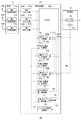
図4は、図1に示される受信装置106の構成を示す。RF部108は、前処理部114と総称する第1前処理部114a、第2前処理部114b、第n前処理部114nを含み、信号処理部110は、BB入力部116と総称する第1BB入力部116a、第2BB入力部116b、第nBB入力部116n、合成部118、ウエイト計算部120と総称する第1ウエイト計算部120a、第2ウエイト計算部120b、第nウエイト計算部120n、立ち上がり検出部122、制御部124、トレーニング信号記憶部126、初期値計算部10と総称する第1初期値計算部10a、第2初期値計算部10b、第n初期値計算部10n、位相誤差推定部12を含み、復調部112は、判定部128、加算部130を含む。
【0028】
また、信号として、ベースバンド受信信号300と総称する第1ベースバンド受信信号300a、第2ベースバンド受信信号300b、第nベースバンド受信信号300n、トレーニング信号302、位相誤差信号304、制御信号306、誤差信号308、重み係数310と総称する第1重み係数310a、第2重み係数310b、第n重み係数310n、相関値312と総称する第1相関値312a、第2相関値312b、第n相関値312nを含む。
【0029】
前処理部114は、無線周波数の信号をベースバンド受信信号300に変換する。
BB入力部116は、ベースバンド受信信号300を受けつける。i番目のアンテナで受信されるベースバンド受信信号300xi(t)は以下のとおりである。
【数1】
【0030】
立ち上がり検出部122は、ベースバンド受信信号300から信号処理部110の動作のトリガーとなるバースト信号の先頭を検出する。検出したバースト信号の先頭のタイミングは制御部124に報告され、制御部124は、先頭タイミングからトレーニング信号302区間の終了タイミングを計算し、これらのタイミングを制御信号306として、必要に応じて各部に通知する。
トレーニング信号記憶部126は、トレーニング信号302を記憶し、必要に応じて、トレーニング信号302を出力する。
【0031】
初期値計算部10は、トレーニング信号302区間中に、ベースバンド受信信号300とトレーニング信号302の相関処理によって、相関値312を計算する。さらに、ベースバンド受信信号300が直接入力されるので、処理遅延も小さい。結果の相関値312Ciは以下の通りである。
【数2】
【0032】
位相誤差推定部12は、トレーニング信号302区間中に初期値計算部10と独立して、ベースバンド受信信号300とトレーニング信号302から、送信装置100と受信装置106が有する周波数発振器の周波数偏差を推定し、周波数偏差によって生じる位相誤差を位相誤差信号304として出力する。位相誤差信号304POは、以下の通りである。
【数3】
【数4】
【0033】
合成部118は、ベースバンド受信信号300を重み係数310で重み付けした後、それらを加算する。加算結果y(t)は、以下の通りである。
【数5】
【0034】
加算部130は、ウエイト計算部120のLMSアルゴリズムで使用するための誤差信号308を、合成した信号と判定した信号の差分により生成する。誤差信号308が小さくなるように、LMSアルゴリズムは重み係数310を制御するため、理想状態において、誤差信号308はゼロとなる。
【0035】
図5から図7は、第1前処理部114aのさまざまな構成を示す。図2や図3で示した異なる通信システム間の相違は、受信装置106における第1前処理部114aで吸収され、これに続く信号処理部110は、一般に通信システムの相違を意識することなく動作可能となる。図5の第1前処理部114aは、図2に示した簡易電話システムや携帯電話のようなシングルキャリア通信システムに対応し、周波数変換部136、準同期検波部138、AGC140(Automatic Gain Control)、AD変換部142、タイミング検出部144を含む。図6の第1前処理部114aは、W―CDMA(Wideband―Code Division Multiple Access)やIEEE802.11bに準拠した無線LANのようなスペクトラム拡散通信システムに対応し、逆拡散部172が付加される。図7の第1前処理部114aは、図3に示したIEEE802.11aやHiperLAN/2のようなマルチキャリア通信システムに対応し、フーリエ変換部174が付加される。
【0036】
周波数変換部136は、無線周波数の信号をひとつまたは複数の中間周波数の信号等に変換する。
準同期検波部138は、中間周波数の信号を周波数発振器により、直交検波し、ベースバンドのアナログ信号を生成する。準同期検波部138に含まれる周波数発振器は、送信装置100にある周波数発振器と独立して動作するため、一般的にふたつの周波数発振器間の周波数は異なる。
【0037】
AGC140は、ベースバンドのアナログ信号の振幅をAD変換部142のダイナミックレンジ内の振幅にするために、利得を自動的に制御する。
AD変換部142は、ベースバンドのアナログ信号をデジタル信号に変換する。デジタル信号に変換するためのサンプリング間隔は、デジタル化による信号の劣化を抑えるために、通常、シンボル間隔より短く設定する。ここでは、サンプリング間隔をシンボル間隔の1/2とする(以下、このサンプリング間隔でデジタル化された信号を「高速デジタル信号」という)。
【0038】
タイミング検出部144は、高速デジタル信号から、最適なサンプリングタイミングのベースバンド受信信号300を選択する。あるいは、高速デジタル信号に対して、合成等の処理を施し、最適なサンプリングタイミングを有するベースバンド受信信号300を生成する。
図6の逆拡散部172は、ベースバンド受信信号300を、予め規定されている符号系列で相関処理する。図7のフーリエ変換部174は、ベースバンド受信信号300を、フーリエ変換する。
【0039】
図8は、タイミング検出部144の構成を示す。タイミング検出部144は、遅延部146と総称する第1遅延部146a、第2遅延部146b、第n−1遅延部146n−1、乗算部150と総称する第1乗算部150a、第2乗算部150b、第n−1乗算部150n−1、第n乗算部150n、データ記憶部152と総称する第1データ記憶部152a、第2データ記憶部152b、第n−1データ記憶部152n−1、第nデータ記憶部152n、加算部154、判定部156、主信号遅延部158、選択部160を含む。
【0040】
遅延部146は、入力した高速デジタル信号を相関処理のために遅延させる。高速デジタル信号のサンプリング間隔は、シンボル間隔の1/2であるが、遅延部146の遅延量はシンボル間隔に設定されているため、ひとつおきの高速デジタル信号が乗算部150に出力される。
データ記憶部152は、タイミング同期のためのプリアンブル信号をそれぞれ1シンボル記憶する。
乗算部150は、高速デジタル信号とプリアンブル信号を乗算し、その結果は加算部154で加算される。
【0041】
判定部156は、加算結果をもとに、最適なサンプリングタイミングを選択する。高速デジタル信号のサンプリング間隔はシンボル間隔の1/2であり、加算に使用される高速デジタル信号の間隔はシンボル間隔であるため、ひとつおきの高速デジタル信号に対する加算結果が、ひとつのサンプリングタイミングをずらして2種類存在する。判定部156は、2種類の加算結果を比較し、加算結果が大きい方のタイミングを最適なサンプリングタイミングと判定する。なお、この判定は、1度の比較によってなされる必要はなく、数回の比較結果をもとになされてもよい。
【0042】
主信号遅延部158は、判定部156が最適なサンプリングタイミングを判定するまで、高速デジタル信号を遅延させる。
選択部160は、高速デジタル信号から、最適サンプリングタイミングに対応するベースバンド受信信号300を選択する。ここでは、2個の連続した高速デジタル信号のうち、1個を順次選択する。
【0043】
図9は、信号処理部110に含まれる立ち上がり検出部122の構成を示す。立ち上がり検出部122は、電力計算部162、判定部164を含む。
電力計算部162は、ベースバンド受信信号300の受信電力をそれぞれ計算し、それらを合計することにより、すべてのアンテナ134によって受信される信号の電力を求める。
判定部164は、受信電力を予め既定してある条件と比較し、その条件が満たされた場合に、バースト信号の先頭が検出されたと判定する。
【0044】
図10は、立ち上がり検出部122の動作を示す。判定部164は、内部のカウンタTをゼロにセットする(S10)。電力計算部162は、ベースバンド受信信号300から受信電力を計算する(S12)。判定部164は、受信電力をしきい値と比較し、しきい値より大きい場合(S14のY)、Tに1を加算する(S16)。Tが規定されている値τより大きくなった場合(S18のY)、バースト信号の先頭を検出したとする。バースト信号の先頭が検出されるまでは、以上の処理を繰り返す(S14のN、S18のN)。
【0045】
図11は、第1初期値計算部10aの構成を示す。第1初期値計算部10aは、主信号遅延部14、複素共役部16、乗算部18、加算部20、遅延部22を含む。
主信号遅延部14は、立ち上がり検出部122によって検出されるタイミングと同期させるために、第1ベースバンド受信信号300aを遅延させる。複素共役部16は、第1ベースバンド受信信号300aを複素共役に変換する。乗算部18は、複素共役の第1ベースバンド受信信号300aとトレーニング信号302を乗算する。
加算部20と遅延部22により、第1ベースバンド受信信号300aとトレーニング信号302の乗算結果がトレーニング信号302区間において積算され、誤差信号308が求められる。
【0046】
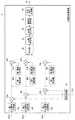
図12は、位相誤差推定部12の構成を示す。位相誤差推定部12は、主信号遅延部26と総称する第1主信号遅延部26a、第2主信号遅延部26b、第n主信号遅延部26n、乗算部28と総称する第1乗算部28a、第2乗算部28b、第n乗算部28n、遅延部30と総称する第1遅延部30a、第2遅延部30b、第n遅延部30n、複素共役部32と総称する第1複素共役部32a、第2複素共役部32b、第n複素共役部32n、乗算部34と総称する第1乗算部34a、第2乗算部34b、第n乗算部34n、平均部36、位相変換部38、位相検出部40、複素数変換部42、補正信号生成部44、複素共役部48を含む。
【0047】
乗算部28は、主信号遅延部26で遅延したベースバンド受信信号300と、複素共役変換されたトレーニング信号302を乗算し、送信信号成分を含まない受信信号Zi(t)を求める。
【数6】
【0048】
遅延部30と複素共役部32は、Zi(t)を遅延した後、複素共役に変換する。当該変換した信号とZi(t)は、乗算部34で乗算される。乗算結果Aiは、以下の通りである。
【数7】
【0049】
平均部36は、各アンテナに対応する乗算結果を平均する。さらに、時間をシフトさせた乗算結果を使用してもよい。
位相変換部38は、アークタンジェントROMを使用して、平均された乗算結果Aを位相信号Bに変換する。
【数8】
【数9】
【0050】
図13は、第1ウエイト計算部120aの構成を示す。第1ウエイト計算部120aは、位相誤差補正部46、複素共役部50、主信号遅延部52、乗算部54、ステップサイズパラメータ記憶部56、乗算部58、加算部60、遅延部62、出力制御部64を含む。
【0051】
位相誤差補正部46は、トレーニング信号302区間が終了する際に、除算を実行して、第1相関値312aを位相誤差信号304によって補正し、初期の第1重み係数310aを求める。
乗算部54は、複素共役部50によって複素共役変換された誤差信号308と、主信号遅延部52によって遅延された第1ベースバンド受信信号300aを乗算し、第1の乗算結果を生成する。
【0052】
乗算部58は、第1の乗算結果にステップサイズパラメータ記憶部56で記憶されているステップサイズパラメータを乗算し、第2の乗算結果を生成する。第2の乗算結果は、遅延部62と加算部60により、フィードバックされた後に、新たな第2の乗算結果と加算され、LMSアルゴリズムによって、加算結果が逐次更新される。この加算結果が第1重み係数310aとして出力される。
【0053】
出力制御部64は、複数の信号の入力を変更するスイッチである。トレーニング信号302区間が終了する際に、出力制御部64は位相誤差補正部46からの初期の第1重み係数310aを入力し、第1ウエイト計算部120aから出力する。データ区間において、出力制御部64は加算部60の加算結果を入力し、それを第1重み係数310aとして出力する。
【0054】
図14は、信号処理部110に含まれる合成部118の構成を示す。合成部118は、遅延部166と総称する第1遅延部166a、第2遅延部166b、第n遅延部166n、乗算部168と総称する第1乗算部168a、第2乗算部168b、第n乗算部168n、加算部170を含む。
乗算部168は、遅延部166によって遅延されたベースバンド受信信号300と重み係数310を乗算する。加算部170は、すべての乗算結果を加算する。
【0055】
以上の構成による受信装置106の動作は以下の通りである。複数のアンテナ134によって受信された信号は、直交検波等によってベースバンド受信信号300に変換される。立ち上がり検出部122が、ベースバンド受信信号300よりバースト信号の先頭のタイミングを検出すると、トレーニング信号302区間が開始される。トレーニング信号302区間中において、初期値計算部10は、ベースバンド受信信号300とトレーニング信号302の相関処理を実行し、同時に位相誤差推定部12はベースバンド受信信号300とトレーニング信号302から位相誤差を推定する。
【0056】
トレーニング信号302区間が終了する際に、位相誤差補正部46は、初期値計算部10から出力される相関値312を、位相誤差推定部12から出力される位相誤差信号304で補正し、初期の重み係数310を生成する。データ信号区間が開始した際、合成部118はベースバンド受信信号300を初期の重み係数310で重み付けして加算する。データ信号区間において、ウエイト計算部120はベースバンド受信信号300と誤差信号308をもとに、重み係数310を、初期の重み係数310から、繰り返し更新する。合成部118は、ベースバンド受信信号300を更新された重み係数310で重み付けして加算する。
【0057】
実施の形態1によれば、本装置は簡易な演算回路で実現可能である。また、初期の重み係数の推定のための相関処理と周波数偏差が並列に実行され、互いの処理結果を使用しないため、処理遅延を小さくできる。また、周波数発振器の周波数偏差による推定精度の劣化を改善可能である。
【0058】
(実施の形態2)
実施の形態2は、実施の形態1と同様に受信信号に含まれるトレーニング信号区間において、送信装置と受信装置の周波数発振器の周波数偏差を推定する。実施の形態1は、受信信号からトレーニング信号の信号成分を除去した後、周波数偏差を推定した。一方、実施の形態2は、トレーニング信号がトレーニング信号より短い周期の信号系列の繰り返しによって構成されている場合において、繰り返しによって周期的に出現する同一信号間で周波数偏差を推定するために、受信信号からトレーニング信号の信号成分を除去することが不要になり、除去のための乗算器も不要になる。
【0059】
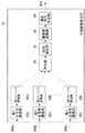
図15は、実施の形態2に係る位相誤差推定部12の構成を示す。図15の位相誤差推定部12は、図12の位相誤差推定部12と比較して、第1乗算部28a、第2乗算部28b、第n乗算部28nが削除されている。実施の形態2では、乗算部34で乗算される信号が同一の送信信号を含む必要があるため、それを満たすよう遅延部30の遅延量を設定する。図2のバーストフォーマットにおいて、プリアンブルは交番符号により構成されているため、2シンボルごとに同一の値となる。そのため、遅延部30はベースバンド受信信号300を2シンボル遅延させるように設定される。図3のバーストフォーマットの1OFDMシンボルごとに同一の値となる区間において、遅延部30は1OFDMシンボルに設定される。一方、1/5OFDMシンボルごとに同一の値となる区間において、遅延部30は1/5OFDMシンボルに設定される。
【0060】
実施の形態2によれば、受信信号から送信信号成分を除去せずに周波数偏差が推定できるため、演算回路の規模をより削減可能である。
【0061】
(実施の形態3)
実施の形態3は、実施の形態1や2と同様に、送信装置と受信装置の周波数発振器の周波数偏差を推定する。実施の形態1や2は、トレーニング信号区間において、受信信号を遅延させた信号と受信信号から、時間軸方向において周波数偏差を推定した。一方、実施の形態3は、受信信号をフーリエ変換し、周波数空間の受信信号から、周波数軸方向に周波数偏差を推定する。周波数空間に変換することにより、受信信号がトレーニング信号であるか、データ信号であるかによらず周波数偏差を推定できる。その結果、トレーニング信号区間よりも長い時間で、より精度の高い周波数偏差を推定できる。
【0062】
図16は、実施の形態3に係る位相誤差推定部12の構成を示す。位相誤差推定部12は、第1主信号遅延部26a、第2主信号遅延部26b、第n主信号遅延部26n、フーリエ変換部66と総称する第1フーリエ変換部66a、第2フーリエ変換部66b、第nフーリエ変換部66n、平均部36、位相変換部38、複素数変換部42、補正信号生成部44を含む。
【0063】
フーリエ変換部66は、主信号遅延部26によって遅延されたベースバンド受信信号300をフーリエ変換し、周波数空間の信号を出力する。この周波数空間の信号は、平均部36で平均処理された後、位相変換部38で電力あるいは振幅のピークが検出される。このピークに対応する周波数の値が、送信装置100と受信装置106の周波数発振器間の周波数偏差であると推定する。以降の処理は、図14の位相誤差推定部12と同一である。
【0064】
実施の形態3によれば、トレーニング信号区間よりも長い時間において、周波数偏差の推定ができるため、その推定精度が向上する。
以上、本発明を実施の形態をもとに説明した。この実施の形態は例示であり、それらの各構成要素や各処理プロセスの組合せにいろいろな変形例が可能なこと、またそうした変形例も本発明の範囲にあることは当業者に理解されるところである。
【0065】
実施の形態において、信号処理部110は、アダプティブアレイアンテナにおける受信信号の合成に適用されているが、それ以外に適用されてもよく、例えば、適応等化器がある。その場合、合成部118の構成が実施の形態と異なり、FIRフィルタのごとく、ひとつの受信信号を複数の遅延素子で遅延させ、遅延させた複数の受信信号と複数の重み係数をそれぞれ乗算した後に、合成する構成となる。また、キャリア再生回路に適用されてもよい。その場合、合成部118における乗算部168がひとつのみになる。つまり、信号処理部110は、相関処理による位相誤差が生じる場合に、適用可能である。
【0066】
実施の形態において、ウエイト計算部120は、適応アルゴリズムとしてLMSアルゴリズムを使用している。しかし、これ以外のRLSアルゴリズムなどが使用されてもよく、さらに、重み係数が更新されなくてもよい。つまり、想定される無線伝搬環境や演算回路規模などに応じて、選択されればよい。
実施の形態1において、位相誤差推定部12は、遅延部30と乗算部34を含んでいる。しかし、位相誤差推定部12が単独で遅延部30と乗算部34を使用する必要はなく、例えば、AFC(Automatic Frequency Control)と共用してもよい。つまり、ひとつの回路を共有して、回路規模を小さくしてもよい。
【0067】
実施の形態1において、立ち上がり検出部122は、ベースバンド受信信号300の電力を計算し、それをもとにバースト信号の立ち上がりを検出している。しかし、バースト信号の立ち上がり検出は、これ以外の構成によって実現されてもよい。例えば、タイミング検出部144の構成として示したマッチドフィルタにより検出することも可能である。つまり、正確にバースト信号の立ち上がりが検出されればよい。
【0068】
実施の形態1において、位相誤差推定部12に含まれる遅延部30の遅延時間を2シンボルとした。しかし、この遅延時間はこれに限られない。例えば、1シンボルやトレーニング信号の最初と最後のシンボルの間隔としてもよい。つまり、遅延部30の遅延時間は、周波数発振器の安定度と要求される周波数偏差推定精度などによって最適なものとすればよい。
【0069】
実施の形態1において、初期値計算部10や位相誤差推定部12が処理を行う時間をトレーニング信号区間とした。しかし、これに限られず、例えば、トレーニング信号区間より短い時間であってもよい。つまり、トレーニング信号区間の長さと、要求される推定精度により、設定されればよい。
【0070】
【発明の効果】
本発明によれば、応答特性を簡易な演算回路で高速に推定できる。また、送信装置と受信装置の周波数発振器の周波数偏差による応答特性の推定精度の劣化を改善できる。また、送信装置と受信装置の周波数発振器の周波数偏差の推定精度を向上できる。
【図面の簡単な説明】
【図1】 実施の形態1に係る通信システムを示す構成図である。
【図2】 実施の形態1に係るバーストフォーマットを示す図である。
【図3】 実施の形態1に係るバーストフォーマットを示す図である。
【図4】 実施の形態1に係る受信装置の構成を示す図である。
【図5】 図4の第1前処理部の構成を示す図である。
【図6】 図4の第1前処理部の構成を示す図である。
【図7】 図4の第1前処理部の構成を示す図である。
【図8】 図5、6、7のタイミング検出部の構成を示す図である。
【図9】 図4の立ち上がり検出部の構成を示す図である。
【図10】 図9の立ち上がり検出部の動作の手順を示す図である。
【図11】 図4の第1初期値計算部の構成を示す図である。
【図12】 図4の位相誤差推定部の構成を示す図である。
【図13】 図4の第1ウエイト計算部の構成を示す図である。
【図14】 図4の合成部の構成を示す図である。
【図15】 実施の形態2に係る位相誤差推定部の構成を示す図である。
【図16】 実施の形態3に係る位相誤差推定部の構成を示す図である。
【符号の説明】
10 初期値計算部、 12 位相誤差推定部、 100 送信装置、 102 変調部、 104 RF部、 106 受信装置、 108 RF部、 110 信号処理部、 112 復調部、 114 前処理部、 116 BB入力部、 118 合成部、 120 ウエイト計算部、 122 立ち上がり検出部、 124 制御部、 126 トレーニング信号記憶部、 128 判定部、 130 加算部、 132 アンテナ、 134 アンテナ、 300 ベースバンド受信信号、 302 トレーニング信号、 304 位相誤差信号、 306 制御信号、 308 誤差信号、 310 重み係数、 312 相関値。[0001]
BACKGROUND OF THE INVENTION
The present invention relates to reception technology. . Especially radio signals received by multiple antennasReceiving method and apparatus for combining About.
[0002]
[Prior art]
In wireless communication, effective use of limited frequency resources is generally desired. In order to effectively use frequency resources, for example, radio waves of the same frequency are repeatedly used at a distance as close as possible. However, in that case, communication quality deteriorates due to co-channel interference from a nearby radio base station or radio mobile station using the same frequency. One technique for preventing degradation of communication quality due to co-channel interference is the adaptive array antenna technique.
[0003]
In the adaptive array antenna technique, signals received by a plurality of antennas are weighted with different weighting factors and combined. The weighting factor is adaptively updated so that an error signal between the signal to be transmitted determined from the combined signal and the combined signal becomes small. For adaptive updating of the weighting factor, for example, an adaptive algorithm such as an RLS (Recursive Least Squares) algorithm or an LMS (Least Mean Squares) algorithm is used. The RLS algorithm generally converges at a high speed, but since the calculation is complicated, a high-speed arithmetic circuit or a large-scale arithmetic circuit is required. The LMS algorithm can be realized with a simpler arithmetic circuit than the RLS algorithm, but its convergence speed is slow (see, for example, Patent Document 1).
[0004]
[Patent Document 1]
JP 2002-26788 A
[0005]
[Problems to be solved by the invention]
One technique for determining a weighting factor at high speed with a simple arithmetic circuit is a technique for determining a weighting factor by a correlation process between a known transmission signal and a reception signal. However, unlike the adaptive algorithm, the technique using correlation processing does not follow environmental fluctuations.For example, if there is a frequency deviation between the frequency oscillators of the transmitter and receiver, the frequency deviation is reflected as an error in the weighting factor. The In general, in an adaptive array antenna, when a weighting factor having an error is used, reception characteristics deteriorate.
[0006]
The present inventor has recognized this situation and made the present invention, and its purpose is to speed up response characteristics with a simple arithmetic circuit.Estimated receiving technology Is to provide. In addition, the estimation accuracy of the response characteristics is degraded due to the frequency deviation of the frequency oscillators of the transmitter and receiver.Improved reception technology Is to provide. In addition, the estimation accuracy of the frequency deviation of the frequency oscillator of the transmitter and receiverImproved reception technology Is to provide.
[0007]
[Means for Solving the Problems]
One embodiment of the present invention is a response characteristic estimation device. The apparatus includes: an input unit that inputs a received signal; a correlation processing unit that performs correlation processing between the received signal and a known transmission signal; and an input reception that is input to a known transmission signal from the received signal and the known transmission signal. Phase error estimator that estimates the phase error of the signal, and phase error correction that estimates the response characteristics of the input received signal with respect to a known transmitted signal by correcting the correlation processing result based on the estimated phase error Part.
[0008]
In “Estimating the phase error of the received signal relative to the known transmitted signal from the received signal and the known transmitted signal”, the “phase” using the “input received signal” and “known transmitted signal” directly is used. The “error” may be estimated, or may be estimated indirectly. Indirect use is, for example, a case where the periodicity of a “known transmission signal” is used.
The “response characteristics” include those obtained by transforming the response characteristics based on a predetermined rule such as those obtained by complex conjugate transformation and those obtained by linear transformation of the response characteristics.
[0009]
The known transmission signal is continuously included in a predetermined section in the received signal, and the response characteristic estimation apparatus includes a control unit that detects the end point of the section in which the known transmission signal is continuous from the input received signal. In addition. In this apparatus, the phase error correction unit may correct the correlation processing result based on the estimated phase error at the detected end point. “Continuous” does not need to be continuous for a long time, but may be continuous for a short time. Further, if the device recognizes the regularity, it includes a discrete case, that is, includes everything that the device can recognize as “continuous”.
[0010]
Since the correlation processing is performed in parallel with the estimation of the phase error by the above apparatus, both processes are not delayed, and high-speed response characteristics can be estimated. Furthermore, since the correlation processing result is corrected with the estimated phase error, it is possible to estimate the response characteristic with high accuracy.
[0011]
Another aspect of the present invention is a response characteristic estimation method. The method includes the steps of inputting a received signal, correlating the input received signal with a known transmission signal, and inputting the phase of the received signal relative to the known transmission signal from the received signal and the known transmission signal. An error estimation step and a step of estimating a response characteristic of an input reception signal with respect to a known transmission signal by correcting a correlation processing result based on the estimated phase error are included.
The known transmission signal is continuously included in a predetermined section in the received signal, and the response characteristic estimation method further detects the end point of the section in which the known transmission signal is continuous from the input received signal. Including the steps of: In this method, the step of estimating the response characteristic of the input reception signal with respect to the known transmission signal may correct the correlation processing result based on the estimated phase error at the detected end point.
[0012]
Yet another embodiment of the present invention is a program. The program includes a step of inputting a reception signal, a step of correlating the input reception signal and a known transmission signal, and a phase of the input reception signal with respect to the known transmission signal from the input reception signal and the known transmission signal. An error estimation step and a step of estimating a response characteristic of an input reception signal with respect to a known transmission signal by correcting a correlation processing result based on the estimated phase error are included.
The known transmission signal is continuously included in a predetermined section in the reception signal, and the program further includes a step of detecting an end point of the section in which the known transmission signal is continuous from the input reception signal. Including. In this program, the step of estimating the response characteristic of the input reception signal with respect to the known transmission signal may correct the correlation processing result based on the estimated phase error at the detected end point.
[0013]
Yet another embodiment of the present invention is a receiving device. The apparatus includes: an input unit that inputs a plurality of received signals; a correlation processing unit that correlates each of the input received signals and a known transmission signal; and at least one of the input received signals A phase error estimator that estimates at least one phase error of a plurality of input received signals with respect to a known transmission signal, and a plurality of correlation processing results based on the estimated phase error. A phase error correction unit that generates a plurality of weighting factors by correction, and a combining unit that combines the plurality of input reception signals and the plurality of weighting factors in association with each other and then combines the multiplication results.
[0014]
The phase error estimation unit estimates a phase error of each of a plurality of input reception signals with respect to a known transmission signal from a plurality of input reception signals and a known transmission signal, and averages the estimated plurality of phase errors. The final phase error may be estimated again.
The known transmission signal is continuously included in a predetermined section in the received signal, and the receiving apparatus further controls, from a plurality of input reception signals, the end point of the section in which the known transmission signal is continuous. Part. In this apparatus, the phase error correction unit may correct the results of the plurality of correlation processes based on the estimated phase error at the detected end point.
[0015]
Yet another embodiment of the present invention is a reception method. The method includes a step of inputting a plurality of reception signals, a step of correlating each of the input reception signals and a known transmission signal, at least one of the plurality of input reception signals, and a known transmission. From the signal, estimating a phase error of at least one of a plurality of received signals input to a known transmission signal, and correcting each of a plurality of correlation processing results based on the estimated phase error, A step of generating a plurality of weighting factors, and a step of multiplying the plurality of input received signals and the plurality of weighting factors in correspondence with each other and then combining the multiplication results.
[0016]
The step of estimating the phase error of at least one of the plurality of input reception signals with respect to the known transmission signal includes the step of estimating the plurality of input reception signals with respect to the known transmission signal from the plurality of input reception signals and the known transmission signal. The final phase error may be estimated again by estimating each phase error and averaging the estimated plurality of phase errors.
The known transmission signal is continuously included in a predetermined section in the reception signal, and the reception method further includes a step of detecting an end point of a section in which the known transmission signal is continuous from a plurality of input reception signals. including. In this method, the step of generating a plurality of weighting factors may correct the results of the plurality of correlation processes at the detected end point based on the estimated phase error.
[0017]
Yet another embodiment of the present invention is a program. The program includes a step of inputting a plurality of reception signals, a step of correlating each of the input reception signals and a known transmission signal, at least one of the plurality of input reception signals, and a known transmission. From the signal, estimating a phase error of at least one of a plurality of received signals input to a known transmission signal, and correcting each of a plurality of correlation processing results based on the estimated phase error, A step of generating a plurality of weighting factors, and a step of multiplying the plurality of input received signals and the plurality of weighting factors in correspondence with each other and then combining the multiplication results.
[0018]
The step of estimating the phase error of at least one of the plurality of input reception signals with respect to the known transmission signal includes the step of estimating the plurality of input reception signals with respect to the known transmission signal from the plurality of input reception signals and the known transmission signal. The final phase error may be estimated again by estimating each phase error and averaging the estimated plurality of phase errors.
The known transmission signal is continuously included in a predetermined section in the received signal, and the program further includes a step of detecting an end point of the section in which the known transmission signal is continuous from a plurality of input received signals. Including. In this program, the step of generating a plurality of weighting factors may each correct the result of the plurality of correlation processes based on the estimated phase error at the detected end point.
It should be noted that any combination of the above-described constituent elements and a conversion of the expression of the present invention between a method, an apparatus, a system, a recording medium, a computer program, etc. are also effective as an aspect of the present invention.
[0019]
DETAILED DESCRIPTION OF THE INVENTION
(Embodiment 1)
The first embodiment relates to a receiving apparatus including an adaptive array antenna that receives a radio signal of a burst signal with a plurality of antennas, and weights and combines the received signals with different weighting factors. The burst signal is composed of a known training signal arranged at the head portion and other data signals. In the training signal section, the receiving apparatus according to
[0020]
FIG. 1 shows a communication system including a
[0021]
[0022]
The
The
[0023]
The antenna 134 of the
The
[0024]
The
The
[0025]
2 and 3 correspond to the communication system of FIG. 1, but are burst formats used in different communication systems, and training signals and data signals included therein are also shown. FIG. 2 is a burst format used in a call channel of a simple telephone system. A preamble for use in timing synchronization is arranged between four symbols from the beginning of the burst. Since the preamble and unique word signals are known signals to the
[0026]
FIG. 3 shows a burst format used in an IEEE802.11a speech channel of a wireless LAN (Local Area Network). IEEE802.11a uses an OFDM (Orthogonal Frequency Division Multiplexing) modulation scheme, and the OFDM modulation scheme generally uses the sum of the size of the Fourier transform and the number of symbols in the guard interval as one unit. This one unit is an OFDM symbol in this embodiment. A preamble mainly used for timing synchronization and carrier reproduction is arranged between 4 OFDM symbols from the head of the burst. Since the preamble signal is a known signal to the
[0027]
FIG. 4 shows the configuration of the receiving
[0028]
As signals, a first baseband received
[0029]
The preprocessing unit 114 converts the radio frequency signal into the baseband reception signal 300.
The BB input unit 116 receives the baseband reception signal 300. The baseband received signal 300xi (t) received by the i-th antenna is as follows.
[Expression 1]
[0030]
The rising
The training
[0031]
The initial
[Expression 2]
[0032]
The phase
[Equation 3]
[Expression 4]
[0033]
The
[Equation 5]
[0034]
The
[0035]
5 to 7 show various configurations of the
[0036]
The
The
[0037]
The
The
[0038]
The
The
[0039]
FIG. 8 shows a configuration of the
[0040]
The delay unit 146 delays the input high-speed digital signal for correlation processing. The sampling interval of the high-speed digital signal is ½ of the symbol interval, but since the delay amount of the delay unit 146 is set to the symbol interval, every other high-speed digital signal is output to the multiplier unit 150.
The data storage unit 152 stores one symbol of each preamble signal for timing synchronization.
The multiplier 150 multiplies the high-speed digital signal and the preamble signal, and the result is added by the
[0041]
The
[0042]
The main
The
[0043]
FIG. 9 shows the configuration of the rising
The
The
[0044]
FIG. 10 shows the operation of the rising
[0045]
FIG. 11 shows the configuration of the first
The main
The
[0046]
FIG. 12 shows the configuration of the
[0047]
The multiplier 28 multiplies the baseband reception signal 300 delayed by the main signal delay unit 26 and the
[Formula 6]
[0048]
The
[Expression 7]
[0049]
The averaging
The
[Equation 8]
[Equation 9]
[0050]
FIG. 13 shows the configuration of the first
[0051]
When the
The
[0052]
The
[0053]
The
[0054]
FIG. 14 shows a configuration of the
Multiplier 168 multiplies baseband received signal 300 delayed by delay unit 166 and weighting factor 310.
[0055]
The operation of the receiving
[0056]
When the section of the
[0057]
According to the first embodiment, this apparatus can be realized with a simple arithmetic circuit. Further, since the correlation process for estimating the initial weighting factor and the frequency deviation are executed in parallel and the processing results are not used, the processing delay can be reduced. In addition, it is possible to improve the deterioration of the estimation accuracy due to the frequency deviation of the frequency oscillator.
[0058]
(Embodiment 2)
In the second embodiment, the frequency deviation between the frequency oscillators of the transmission device and the reception device is estimated in the training signal section included in the reception signal, as in the first embodiment. The first embodiment estimates the frequency deviation after removing the signal component of the training signal from the received signal. On the other hand, in the second embodiment, when the training signal is configured by repetition of a signal sequence having a period shorter than that of the training signal, the received signal is used to estimate the frequency deviation between the same signals that appear periodically by repetition. Therefore, it is not necessary to remove the signal component of the training signal from the training signal, and a multiplier for removal is also unnecessary.
[0059]
FIG. 15 shows the configuration of the
[0060]
According to the second embodiment, since the frequency deviation can be estimated without removing the transmission signal component from the received signal, the scale of the arithmetic circuit can be further reduced.
[0061]
(Embodiment 3)
In the third embodiment, as in the first and second embodiments, the frequency deviation between the frequency oscillators of the transmission device and the reception device is estimated. In
[0062]
FIG. 16 shows the configuration of the
[0063]
The Fourier transform unit 66 performs a Fourier transform on the baseband received signal 300 delayed by the main signal delay unit 26, and outputs a frequency space signal. The frequency space signal is averaged by the averaging
[0064]
According to the third embodiment, since the frequency deviation can be estimated in a time longer than the training signal section, the estimation accuracy is improved.
The present invention has been described based on the embodiments. This embodiment is an exemplification, and it will be understood by those skilled in the art that various modifications can be made to combinations of the respective constituent elements and processing processes, and such modifications are also within the scope of the present invention. is there.
[0065]
In the embodiment, the
[0066]
In the embodiment, the weight calculation unit 120 uses an LMS algorithm as an adaptive algorithm. However, other RLS algorithms or the like may be used, and the weighting coefficient may not be updated. In other words, the selection may be made according to the assumed radio propagation environment, arithmetic circuit scale, and the like.
In the first embodiment, the phase
[0067]
In the first embodiment, the rising
[0068]
In the first embodiment, the delay time of the
[0069]
In the first embodiment, the time during which the initial
[0070]
【The invention's effect】
According to the present invention, response characteristics can be estimated at high speed with a simple arithmetic circuit. In addition, it is possible to improve the deterioration of the estimation accuracy of the response characteristics due to the frequency deviation of the frequency oscillators of the transmission device and the reception device. Moreover, the estimation accuracy of the frequency deviation of the frequency oscillators of the transmission device and the reception device can be improved.
[Brief description of the drawings]
FIG. 1 is a configuration diagram showing a communication system according to a first embodiment.
FIG. 2 is a diagram showing a burst format according to the first embodiment.
FIG. 3 is a diagram showing a burst format according to the first embodiment.
4 is a diagram illustrating a configuration of a receiving apparatus according to
FIG. 5 is a diagram illustrating a configuration of a first preprocessing unit in FIG. 4;
6 is a diagram showing a configuration of a first preprocessing unit in FIG. 4; FIG.
7 is a diagram showing a configuration of a first preprocessing unit in FIG. 4; FIG.
FIG. 8 is a diagram illustrating a configuration of a timing detection unit illustrated in FIGS.
9 is a diagram showing a configuration of a rising edge detection unit in FIG. 4;
FIG. 10 is a diagram illustrating an operation procedure of a rising edge detection unit in FIG. 9;
FIG. 11 is a diagram illustrating a configuration of a first initial value calculation unit in FIG. 4;
12 is a diagram illustrating a configuration of a phase error estimation unit in FIG. 4;
13 is a diagram showing a configuration of a first weight calculation unit in FIG. 4;
14 is a diagram illustrating a configuration of a synthesis unit in FIG. 4;
FIG. 15 is a diagram showing a configuration of a phase error estimation unit according to the second embodiment.
FIG. 16 is a diagram showing a configuration of a phase error estimation unit according to the third embodiment.
[Explanation of symbols]
10 initial value calculation unit, 12 phase error estimation unit, 100 transmission device, 102 modulation unit, 104 RF unit, 106 reception device, 108 RF unit, 110 signal processing unit, 112 demodulation unit, 114 preprocessing unit, 116
Claims (9)
Translated fromJapanese前記入力した複数の受信信号と既知の送信信号をそれぞれ相関処理する相関処理部と、
前記相関処理部が処理を実行している期間に、前記相関処理部での処理と並行に、前記入力した複数の受信信号に対する位相誤差を推定する位相誤差推定部と、
前記相関処理部での処理が終了する際に、前記推定した位相誤差をもとに、複数の相関処理した結果をそれぞれ補正することによって、複数の重み係数を生成するウエイト計算部と、
前記入力した複数の受信信号と複数の重み係数を、それぞれ対応させて乗算した後、乗算結果を合成する合成部とを含み、
前記ウエイト計算部は、前記相関処理部での処理が終了した後、補正した複数の重み係数を初期値として、適応アルゴリズムを使用しながら複数の重み係数を更新することを特徴とする受信装置。An input unit for inputting a plurality of received signals,
A correlation processing unit for performing correlation processing on each of the input reception signals and a known transmission signal;
A phase error estimator that estimatesphase errors for the plurality of input received signals in parallel with the processing in the correlation processor during a period in which the correlation processor is executing processing ;
Aweight calculation unit that generates a plurality of weighting coefficients by correcting each of a plurality of correlation processing results based on the estimated phase errorwhen the processing in the correlation processing unit ends ;
A combination unit that combines the plurality of input received signals and the plurality of weighting factors in association with each other, and then combines the multiplication results;
The weight calculation unit updates a plurality of weighting factors while using an adaptive algorithm with the corrected plurality of weighting factors as initial values after the processing in the correlation processing unit is completed .
本受信装置はさらに、前記入力した複数の受信信号から、前記既知の送信信号が連続している区間の終点を検出する制御部を含み、
前記ウエイト計算部は、前記検出した終点において、前記推定した位相誤差をもとに、複数の相関処理した結果をそれぞれ補正することを特徴とする請求項1または2に記載の受信装置。The known transmission signal is continuously included in a predetermined section in the reception signal,
The reception apparatus further includes a control unit that detects an end point of a section in which the known transmission signals are continuous from the plurality of input reception signals,
The weight calculator, in the detected end point, the receiving device according to the basis of the phase error and the estimated, to claim1 or 2, characterized in that for correcting a plurality of correlation processing result respectively.
前記入力した複数の受信信号と既知の送信信号をそれぞれ相関処理するステップと、
前記相関処理するステップにおいて処理を実行している期間に、前記相関処理するステップでの処理と並行に、前記入力した複数の受信信号に対する位相誤差を推定するステップと、
前記相関処理するステップでの処理が終了する際に、前記推定した位相誤差をもとに、複数の相関処理した結果をそれぞれ補正することによって、複数の重み係数を生成するステップと、
入力した複数の受信信号と、補正した複数の重み係数を、それぞれ対応させて乗算した後、乗算結果を合成するステップと、
前記相関処理するステップでの処理が終了した後、補正した複数の重み係数を初期値として、適応アルゴリズムを使用しながら複数の重み係数を更新するステップと、
入力した複数の受信信号と、更新した複数の重み係数を、それぞれ対応させて乗算した後、乗算結果を合成するステップと、
を含むことを特徴とする受信方法。Inputting each of a plurality of received signals;
Correlating each of the plurality of input received signals and known transmission signals;
Estimating aphase error withrespect to the plurality of input received signals in parallel with the processing in the correlation processing step during a period in which the processing is performed in the correlation processing step;
Generating a plurality of weighting factors by correcting each of a plurality of correlation processing results based on the estimated phase errorwhen the processing in the correlation processing step ends ;
Multiplyinga plurality of input received signals and a plurality ofcorrected weighting factors in correspondence with each other, and then combining the multiplication results;
After completion of the processing in the step of performing correlation processing, updating a plurality of weighting factors while using an adaptive algorithm with a plurality of corrected weighting factors as initial values;
A step of multiplyinga plurality of input received signals and a plurality ofupdated weighting factors in correspondence with each other, and then combining the multiplication results;
A receiving method comprising:
本方法はさらに、前記入力した複数の受信信号から、前記既知の送信信号が連続している区間の終点を検出するステップを含み、 The method further includes detecting an end point of a section in which the known transmission signal is continuous from the plurality of input reception signals.
前記複数の重み係数を生成するステップは、前記検出した終点において、前記推定した位相誤差をもとに、複数の相関処理した結果をそれぞれ補正することを特徴とする請求項4または5に記載の受信方法。 6. The step of generating the plurality of weighting factors corrects a result of a plurality of correlation processes based on the estimated phase error at the detected end point, respectively. Reception method.
前記入力した複数の受信信号と既知の送信信号をそれぞれ相関処理するステップと、
前記相関処理するステップにおいて処理を実行している期間に、前記相関処理するステップでの処理と並行に、前記入力した複数の受信信号に対する位相誤差を推定するステップと、
前記相関処理するステップでの処理が終了する際に、前記推定した位相誤差をもとに、複数の相関処理した結果をそれぞれ補正することによって、複数の重み係数を生成するステップと、
入力した複数の受信信号と、補正した複数の重み係数を、それぞれ対応させて乗算した後、乗算結果を合成するステップと、
前記相関処理するステップでの処理が終了した後、補正した複数の重み係数を初期値として、適応アルゴリズムを使用しながら複数の重み係数を更新するステップと、
入力した複数の受信信号と、更新した複数の重み係数を、それぞれ対応させて乗算した後、乗算結果を合成するステップと、
をコンピュータに実行させるためのプログラム。Inputting each of a plurality of received signals;
Correlating each of the plurality of input received signals and known transmission signals;
Estimating aphase error withrespect to the plurality of input received signals in parallel with the processing in the correlation processing step during a period in which the processing is performed in the correlation processing step;
Generating a plurality of weighting factors by correcting each of a plurality of correlation processing results based on the estimated phase errorwhen the processing in the correlation processing step ends ;
Multiplyinga plurality of input received signals and a plurality ofcorrected weighting factors in correspondence with each other, and then combining the multiplication results;
After completion of the processing in the step of performing correlation processing, updating a plurality of weighting factors while using an adaptive algorithm with a plurality of corrected weighting factors as initial values;
A step of multiplyinga plurality of input received signals and a plurality ofupdated weighting factors in correspondence with each other, and then combining the multiplication results;
A program that causes a computer to execute.
本プログラムはさらに、前記入力した複数の受信信号から、前記既知の送信信号が連続している区間の終点を検出するステップを含み、 The program further includes a step of detecting an end point of a section in which the known transmission signals are continuous from the plurality of input reception signals.
前記複数の重み係数を生成するステップは、前記検出した終点において、前記推定した位相誤差をもとに、複数の相関処理した結果をそれぞれ補正することを特徴とする請求項7または8に記載のプログラム。 9. The step of generating the plurality of weighting factors respectively corrects a plurality of correlation processing results based on the estimated phase error at the detected end point. program.
Priority Applications (7)
| Application Number | Priority Date | Filing Date | Title |
|---|---|---|---|
| JP2002337306AJP3973543B2 (en) | 2002-11-20 | 2002-11-20 | Reception method and apparatus |
| TW094119227ATW200536296A (en) | 2002-11-20 | 2003-11-14 | Receiving device utilizing method of estimating response characteristic |
| TW094119226ATW200536285A (en) | 2002-11-20 | 2003-11-14 | Method for estimating response characteristic, and receiving method utilizing the same |
| TW092131950ATWI249295B (en) | 2002-11-20 | 2003-11-14 | Method and apparatus for estimating response characteristic, and receiving method and receiver utilizing the same |
| EP03026576AEP1439676A3 (en) | 2002-11-20 | 2003-11-18 | Diversity reception |
| US10/715,487US7502431B2 (en) | 2002-11-20 | 2003-11-19 | Method and apparatus for estimating response characteristic, and receiving method and receiver utilizing the same |
| CNB2003101180253ACN1303767C (en) | 2002-11-20 | 2003-11-20 | Method and apparatus for estimating response characteristic, and receiving method and receiver utilizing the same |
Applications Claiming Priority (1)
| Application Number | Priority Date | Filing Date | Title |
|---|---|---|---|
| JP2002337306AJP3973543B2 (en) | 2002-11-20 | 2002-11-20 | Reception method and apparatus |
Publications (2)
| Publication Number | Publication Date |
|---|---|
| JP2004173020A JP2004173020A (en) | 2004-06-17 |
| JP3973543B2true JP3973543B2 (en) | 2007-09-12 |
Family
ID=32321838
Family Applications (1)
| Application Number | Title | Priority Date | Filing Date |
|---|---|---|---|
| JP2002337306AExpired - Fee RelatedJP3973543B2 (en) | 2002-11-20 | 2002-11-20 | Reception method and apparatus |
Country Status (5)
| Country | Link |
|---|---|
| US (1) | US7502431B2 (en) |
| EP (1) | EP1439676A3 (en) |
| JP (1) | JP3973543B2 (en) |
| CN (1) | CN1303767C (en) |
| TW (3) | TW200536285A (en) |
Families Citing this family (16)
| Publication number | Priority date | Publication date | Assignee | Title |
|---|---|---|---|---|
| US20030171834A1 (en)* | 2002-03-07 | 2003-09-11 | Silvester Kelan C. | Method and apparatus for connecting a portable media player wirelessly to an automobile entertainment system |
| JP4090331B2 (en)* | 2002-11-20 | 2008-05-28 | 三洋電機株式会社 | Reception method and apparatus |
| US9248003B2 (en)* | 2002-12-30 | 2016-02-02 | Varian Medical Systems, Inc. | Receiver used in marker localization sensing system and tunable to marker frequency |
| JP3748449B2 (en)* | 2003-03-31 | 2006-02-22 | 株式会社東芝 | OFDM receiver |
| US7437135B2 (en) | 2003-10-30 | 2008-10-14 | Interdigital Technology Corporation | Joint channel equalizer interference canceller advanced receiver |
| US7684849B2 (en)* | 2003-12-31 | 2010-03-23 | Calypso Medical Technologies, Inc. | Marker localization sensing system synchronized with radiation source |
| US20050154280A1 (en)* | 2003-12-31 | 2005-07-14 | Wright J. N. | Receiver used in marker localization sensing system |
| US20050154284A1 (en)* | 2003-12-31 | 2005-07-14 | Wright J. N. | Method and system for calibration of a marker localization sensing array |
| US7400692B2 (en) | 2004-01-14 | 2008-07-15 | Interdigital Technology Corporation | Telescoping window based equalization |
| JP4725356B2 (en)* | 2006-02-23 | 2011-07-13 | 株式会社デンソー | OFDM communication device |
| US8565690B2 (en)* | 2006-11-08 | 2013-10-22 | Massachusetts Institute Of Technology | Method and apparatus for signal searching |
| EP2129069A4 (en) | 2007-03-06 | 2013-10-16 | Mitsubishi Electric Corp | RADIO COMMUNICATION SYSTEM |
| FR2925809B1 (en)* | 2007-12-21 | 2015-12-04 | Thales Sa | METHOD FOR TRANSMITTING A COMPLEX SIGNAL, MODULE USING ANGULAR MODULATION, FOR EXAMPLE OF A GMSK TYPE, AND CORRESPONDING DEVICE |
| JP4991593B2 (en)* | 2008-02-19 | 2012-08-01 | 株式会社日立製作所 | Wireless communication device |
| JP5645238B2 (en)* | 2008-09-19 | 2014-12-24 | 日本電気株式会社 | Wireless communication system control method and wireless communication system |
| TWI806456B (en)* | 2022-03-01 | 2023-06-21 | 瑞昱半導體股份有限公司 | Signal receiving apparatus and operation method thereof having phase compensation mechanism |
Family Cites Families (22)
| Publication number | Priority date | Publication date | Assignee | Title |
|---|---|---|---|---|
| US4599732A (en) | 1984-04-17 | 1986-07-08 | Harris Corporation | Technique for acquiring timing and frequency synchronization for modem utilizing known (non-data) symbols as part of their normal transmitted data format |
| US5031193A (en)* | 1989-11-13 | 1991-07-09 | Motorola, Inc. | Method and apparatus for diversity reception of time-dispersed signals |
| US5602881A (en)* | 1992-04-24 | 1997-02-11 | Oki Electric Industry Co., Ltd. | Receiver for a digital communication system |
| KR960011125B1 (en)* | 1993-01-30 | 1996-08-20 | 삼성전자 주식회사 | Tdma |
| JP3301555B2 (en)* | 1993-03-30 | 2002-07-15 | ソニー株式会社 | Wireless receiver |
| US5627863A (en) | 1994-07-15 | 1997-05-06 | Amati Communications Corporation | Frame synchronization in multicarrier transmission systems |
| JP3116735B2 (en) | 1994-08-11 | 2000-12-11 | 松下電器産業株式会社 | Automatic frequency correction device |
| JPH11313364A (en)* | 1997-10-28 | 1999-11-09 | Sanyo Electric Co Ltd | Method and system for assigning transmission channel |
| JP3302634B2 (en)* | 1997-12-16 | 2002-07-15 | 松下電器産業株式会社 | Data communication device and method |
| JP3587985B2 (en) | 1998-02-19 | 2004-11-10 | 三菱電機株式会社 | Adaptive antenna |
| FI112739B (en)* | 1998-05-25 | 2003-12-31 | Nokia Corp | Method and apparatus for detecting an interfering signal in a radio receiver |
| JP2000022611A (en)* | 1998-06-29 | 2000-01-21 | Matsushita Electric Ind Co Ltd | Transmission power control method and wireless communication device |
| JP2000032069A (en)* | 1998-07-08 | 2000-01-28 | Nec Corp | Packet configuration method and packet receiver |
| US6728326B1 (en) | 2000-03-20 | 2004-04-27 | Ericsson Inc. | Reduced complexity for initial mobile terminal synchronization |
| JP2001285189A (en) | 2000-04-03 | 2001-10-12 | Sanyo Electric Co Ltd | Wireless base station and program storage medium |
| JP3505468B2 (en) | 2000-04-03 | 2004-03-08 | 三洋電機株式会社 | Wireless device |
| JP2002026788A (en)* | 2000-07-13 | 2002-01-25 | Matsushita Electric Ind Co Ltd | Receiver |
| JP3464645B2 (en) | 2000-08-30 | 2003-11-10 | 松下電器産業株式会社 | Wireless receiver |
| KR100376803B1 (en) | 2000-09-29 | 2003-03-19 | 삼성전자주식회사 | Apparatus for compensating frequency offset and method thereof in orthogonal frequency division multiplexing system |
| US7088782B2 (en)* | 2001-04-24 | 2006-08-08 | Georgia Tech Research Corporation | Time and frequency synchronization in multi-input, multi-output (MIMO) systems |
| EP1540817A4 (en) | 2002-06-12 | 2009-05-27 | Dsp Group Inc | Cck demodulation via symbol decision feedback equalizer |
| US7346131B2 (en)* | 2002-07-10 | 2008-03-18 | Zoran Corporation | System and method for pre-FFT OFDM fine synchronization |
- 2002
- 2002-11-20JPJP2002337306Apatent/JP3973543B2/ennot_activeExpired - Fee Related
- 2003
- 2003-11-14TWTW094119226Apatent/TW200536285A/enunknown
- 2003-11-14TWTW094119227Apatent/TW200536296A/enunknown
- 2003-11-14TWTW092131950Apatent/TWI249295B/ennot_activeIP Right Cessation
- 2003-11-18EPEP03026576Apatent/EP1439676A3/ennot_activeWithdrawn
- 2003-11-19USUS10/715,487patent/US7502431B2/ennot_activeExpired - Fee Related
- 2003-11-20CNCNB2003101180253Apatent/CN1303767C/ennot_activeExpired - Fee Related
Also Published As
| Publication number | Publication date |
|---|---|
| US20040101073A1 (en) | 2004-05-27 |
| US7502431B2 (en) | 2009-03-10 |
| TWI249295B (en) | 2006-02-11 |
| CN1503471A (en) | 2004-06-09 |
| TW200536285A (en) | 2005-11-01 |
| JP2004173020A (en) | 2004-06-17 |
| TW200536296A (en) | 2005-11-01 |
| EP1439676A2 (en) | 2004-07-21 |
| TW200423579A (en) | 2004-11-01 |
| CN1303767C (en) | 2007-03-07 |
| EP1439676A3 (en) | 2007-08-01 |
Similar Documents
| Publication | Publication Date | Title |
|---|---|---|
| JP4090331B2 (en) | Reception method and apparatus | |
| JP3973543B2 (en) | Reception method and apparatus | |
| JP3933597B2 (en) | Transmission method and wireless device using the same | |
| US7643587B2 (en) | Frequency offset estimating method and frequency offset correcting apparatus utilizing said method | |
| JP4338624B2 (en) | Frequency offset estimation method and frequency offset correction apparatus using the same | |
| JP4014502B2 (en) | Reception response characteristic holding method and wireless device using the same | |
| JP4187763B2 (en) | Receiving method, receiving apparatus using the same, wireless mobile station equipped with receiving apparatus, and wireless apparatus equipped with receiving apparatus | |
| JP4187762B2 (en) | Receiving method, receiving apparatus using the same, wireless mobile station equipped with receiving apparatus, and wireless apparatus equipped with receiving apparatus | |
| JP4148955B2 (en) | RECEPTION METHOD, RECEPTION DEVICE USING SAME, RADIO MOBILE STATION, RADIO DEVICE | |
| JP2018133740A (en) | Radio communication device, phase noise correction method, and radio communication system | |
| JP4187761B2 (en) | RECEPTION METHOD, RECEPTION DEVICE USING SAME, RADIO MOBILE STATION, RADIO DEVICE | |
| JP4187760B2 (en) | RECEPTION METHOD, RECEPTION DEVICE USING SAME, RADIO MOBILE STATION, RADIO DEVICE |
Legal Events
| Date | Code | Title | Description |
|---|---|---|---|
| A621 | Written request for application examination | Free format text:JAPANESE INTERMEDIATE CODE: A621 Effective date:20040802 | |
| A977 | Report on retrieval | Free format text:JAPANESE INTERMEDIATE CODE: A971007 Effective date:20060815 | |
| A131 | Notification of reasons for refusal | Free format text:JAPANESE INTERMEDIATE CODE: A131 Effective date:20060822 | |
| A521 | Request for written amendment filed | Free format text:JAPANESE INTERMEDIATE CODE: A523 Effective date:20061018 | |
| TRDD | Decision of grant or rejection written | ||
| A01 | Written decision to grant a patent or to grant a registration (utility model) | Free format text:JAPANESE INTERMEDIATE CODE: A01 Effective date:20070515 | |
| A61 | First payment of annual fees (during grant procedure) | Free format text:JAPANESE INTERMEDIATE CODE: A61 Effective date:20070612 | |
| R151 | Written notification of patent or utility model registration | Ref document number:3973543 Country of ref document:JP Free format text:JAPANESE INTERMEDIATE CODE: R151 | |
| FPAY | Renewal fee payment (event date is renewal date of database) | Free format text:PAYMENT UNTIL: 20100622 Year of fee payment:3 | |
| FPAY | Renewal fee payment (event date is renewal date of database) | Free format text:PAYMENT UNTIL: 20110622 Year of fee payment:4 | |
| FPAY | Renewal fee payment (event date is renewal date of database) | Free format text:PAYMENT UNTIL: 20110622 Year of fee payment:4 | |
| FPAY | Renewal fee payment (event date is renewal date of database) | Free format text:PAYMENT UNTIL: 20120622 Year of fee payment:5 | |
| FPAY | Renewal fee payment (event date is renewal date of database) | Free format text:PAYMENT UNTIL: 20130622 Year of fee payment:6 | |
| S111 | Request for change of ownership or part of ownership | Free format text:JAPANESE INTERMEDIATE CODE: R313113 | |
| R350 | Written notification of registration of transfer | Free format text:JAPANESE INTERMEDIATE CODE: R350 | |
| R250 | Receipt of annual fees | Free format text:JAPANESE INTERMEDIATE CODE: R250 | |
| R250 | Receipt of annual fees | Free format text:JAPANESE INTERMEDIATE CODE: R250 | |
| R250 | Receipt of annual fees | Free format text:JAPANESE INTERMEDIATE CODE: R250 | |
| R250 | Receipt of annual fees | Free format text:JAPANESE INTERMEDIATE CODE: R250 | |
| R250 | Receipt of annual fees | Free format text:JAPANESE INTERMEDIATE CODE: R250 | |
| LAPS | Cancellation because of no payment of annual fees |