JP3972755B2 - Position measuring method, and terminal device and server used therefor - Google Patents
Position measuring method, and terminal device and server used thereforDownload PDFInfo
- Publication number
- JP3972755B2 JP3972755B2JP2002202055AJP2002202055AJP3972755B2JP 3972755 B2JP3972755 B2JP 3972755B2JP 2002202055 AJP2002202055 AJP 2002202055AJP 2002202055 AJP2002202055 AJP 2002202055AJP 3972755 B2JP3972755 B2JP 3972755B2
- Authority
- JP
- Japan
- Prior art keywords
- base station
- terminal
- antenna
- delay profile
- sector
- Prior art date
- Legal status (The legal status is an assumption and is not a legal conclusion. Google has not performed a legal analysis and makes no representation as to the accuracy of the status listed.)
- Expired - Lifetime
Links
Images


Classifications
- G—PHYSICS
- G01—MEASURING; TESTING
- G01S—RADIO DIRECTION-FINDING; RADIO NAVIGATION; DETERMINING DISTANCE OR VELOCITY BY USE OF RADIO WAVES; LOCATING OR PRESENCE-DETECTING BY USE OF THE REFLECTION OR RERADIATION OF RADIO WAVES; ANALOGOUS ARRANGEMENTS USING OTHER WAVES
- G01S5/00—Position-fixing by co-ordinating two or more direction or position line determinations; Position-fixing by co-ordinating two or more distance determinations
- G01S5/02—Position-fixing by co-ordinating two or more direction or position line determinations; Position-fixing by co-ordinating two or more distance determinations using radio waves
- G01S5/14—Determining absolute distances from a plurality of spaced points of known location
- H—ELECTRICITY
- H04—ELECTRIC COMMUNICATION TECHNIQUE
- H04W—WIRELESS COMMUNICATION NETWORKS
- H04W64/00—Locating users or terminals or network equipment for network management purposes, e.g. mobility management
- G—PHYSICS
- G01—MEASURING; TESTING
- G01S—RADIO DIRECTION-FINDING; RADIO NAVIGATION; DETERMINING DISTANCE OR VELOCITY BY USE OF RADIO WAVES; LOCATING OR PRESENCE-DETECTING BY USE OF THE REFLECTION OR RERADIATION OF RADIO WAVES; ANALOGOUS ARRANGEMENTS USING OTHER WAVES
- G01S1/00—Beacons or beacon systems transmitting signals having a characteristic or characteristics capable of being detected by non-directional receivers and defining directions, positions, or position lines fixed relatively to the beacon transmitters; Receivers co-operating therewith
- G01S1/02—Beacons or beacon systems transmitting signals having a characteristic or characteristics capable of being detected by non-directional receivers and defining directions, positions, or position lines fixed relatively to the beacon transmitters; Receivers co-operating therewith using radio waves
- G01S1/04—Details
- G01S1/045—Receivers
- H—ELECTRICITY
- H04—ELECTRIC COMMUNICATION TECHNIQUE
- H04W—WIRELESS COMMUNICATION NETWORKS
- H04W16/00—Network planning, e.g. coverage or traffic planning tools; Network deployment, e.g. resource partitioning or cells structures
- H04W16/24—Cell structures
Landscapes
- Engineering & Computer Science (AREA)
- Physics & Mathematics (AREA)
- General Physics & Mathematics (AREA)
- Radar, Positioning & Navigation (AREA)
- Remote Sensing (AREA)
- Computer Networks & Wireless Communication (AREA)
- Signal Processing (AREA)
- Mobile Radio Communication Systems (AREA)
- Position Fixing By Use Of Radio Waves (AREA)
Description
Translated fromJapanese【0001】
【発明の属する技術分野】
本発明は、無線による位置の測定に関するもので、特にセルラ基地局を信号源とするものに好適な技術に関する。
【0002】
【従来の技術】
広帯域の無線信号を使った端末の位置測定技術では、特開2001-359140にCDMA(符号分割多重接続)信号を使ったシステムが示されている。
図12にその概念を示す。端末1201は、GPS(グローバルポジショニングシステム)1205等により同期した複数の基地局1202、1203、1204が送信する信号(送信符号)1206、1207、1208を受信し、信号の受信タイミングを示す遅延プロファイルを作成する。そして、遅延プロファイルから伝搬距離を推定し、既知の基地局の位置と推定された距離とから端末位置を推定する。
【0003】
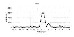
図13に遅延プロファイルの例を示す。遅延プロファイルとは、送信符号と受信信号の相関を計算したものであり、相関の高い時間(タイミング)が信号の受信タイミングを示すことから、伝搬時間の推定に利用されている。
【0004】
幾何学的には位置が異なる3つの基地局からの信号について伝搬距離を推定できれば、三辺測量の原理によって、端末位置を推定することが可能である。さらに、4つ以上の基地局について伝搬距離を推定できれば、例えば、最小二乗法などを用いてより高い精度で端末位置を推定することが可能である。
従って、端末の位置を特定するには、少なくとも場所の異なる三つ以上の基地局の送信符号についてこのような遅延プロファイルを作成することが好ましい。
端末位置の推定精度を向上するためには、異なる場所に存在する基地局を数多く利用できることが好ましい。しかし、一つの送信符号について遅延プロファイルを作成するためには多くのステップ数とメモリ量を必要とする。ゆえに遅延プロファイルを作成できる基地局の送信符号の数は、回路規模の見地から制限される。端末の小型化、省電力化を図れば、この制限は一層厳しいものとなる。
【0005】
ところで、信号源として利用可能な基地局は、一般に指向性アンテナによりセクタと呼ばれる扇形のセルを複数形成している。このような基地局構成は、例えば携帯電話用の無線基地局において通常の構成である。
図14にその一例を示す。基地局1410は、指向性アンテナ1401、1402、1403によって、それぞれ、セクタ1411、1412、1413を形成している。各セクタではそれぞれ異なる信号(送信符号)が送信されているため、同一の基地局には、放射方向の異なる複数の信号源が存在することになる。
【0006】
【発明が解決しようとする課題】
そこで、本発明の課題は、端末の位置測定において遅延プロファイルを作成する際、その作成対象となる信号の信号源である基地局として、より多くの基地局を利用することにある。さらには、これを規模の小さな回路で実現することにある。この際、基地局のセクタに対する送信符号の選択が課題となる。
【0007】
【課題を解決するための手段】
本発明は、受信信号の遅延プロファイルの作成に基づいた無線位置測定方法において、基地局の位置と、各セクタを形成する該基地局の各アンテナの向きとに基づいて、位置測定に用いる基地局のセクタに対する送信符号を選択することを特徴とする。
具体的には、複数のアンテナから送信される信号を端末で受信し、受信信号に基づいて端末の位置を測定する位置測定方法において、アンテナの位置と向きとに基づいて、位置を測定するための信号の送信元となるアンテナを選択することを特徴とする。
位置測定の手法としては、例えば、受信信号の遅延プロファイルを作成し、遅延プロファイルに基づいて端末の位置を測定する手法がある。また、受信信号の受信電力を測定し、受信電力値に基づいて端末の位置を測定する手法がある。
【0008】
ここで、基地局は普通向きの異なる複数のアンテナを備えているので、本発明の他の観点は、通常は一単位として取り扱われる基地局を、複数のアンテナまたはセクタの集合として取り扱うことにもある。
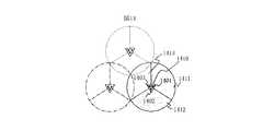
図17にこの概念の一例を示す。黒い四角は位置測定端末の位置を示す。複数の円は基地局を示す。各円は三等分されており、3つのセクタに分割されている。図17に示す比較例では、基地局から発信される信号(電波)のうち測位に利用されるのは、基準基地局およびその隣接基地局7カ所からの信号である。7つの基地局は21のセクタから成り、各セクタの信号は21の回路で並列に処理することができる。
【0009】
本件出願の出願人が先に出願した特願2001-029560の例によれば、各基地局の3つのセクタの信号が処理されるが、測位にもちいられるのは1つのみである。図17の基地局を示す円のうち白い部分に属する信号が回路で処理される。一方、本発明では、回路で処理される信号は、セクタ単位で選択される。従来と同様に21のセクタの信号が並列に処理されるが、信号の発信源となる基地局は13カ所であり、従来よりも多くの位置を基準にして測位が可能となる。
【0010】
アンテナまたは基地局の選択の手順は、種々考えられるが、
(1)任意の基地局(通常は最も近い、あるいは、最も強く受信できる基地局)の位置を基準とする。
(2)基準から所定以上遠距離にある基地局については、基地局のアンテナのうち、向きが基準への向きに最も近いアンテナより放射される送信符号を選択する。
(3)基準から所定以上近距離にある基地局については、該基地局のセクタを形成する全てのアンテナより放射される送信符号を選択する。
【0011】
本発明のその他の形態は、基地局からの信号の受信電力に基づいて位置を測定するた無線位置測定方法において、基地局からの信号の受信電力を測定する際に、送信元となる基地局の位置とそのアンテナの向きとに基づいて、測定対象とする基地局からの信号を受信するための周波数チャネルを決定することを特徴とする無線位置測定方法である。
【0012】
図18は本発明を用いた位置測定システムの全体構成である。左方に位置する携帯端末は、位置測定を行うためのロケーションLSIを備えている。この端末は、複数の基地局のアンテナからの電波を処理する。基地局はネットワークを介して位置検出サーバを含む位置情報センタと接続されている。位置情報センタは課金や認証を司るサーバを含んでも良い。また、さらに他のアプリケーションサービスを提供する他のASPと接続することもできる。
【0013】
上記の携帯端末は、複数のアンテナから送信される信号の受信を行い受信信号を形成するアンテナ、上記受信信号を入力として高周波信号とベースバンド信号との変換を行うRF回路、上記RF回路により形成されたアナログ信号をディジタル信号に変換するAD変換部、上記ディジタル信号からパイロット信号を取り出すために逆拡散を行う逆拡散部、上記逆拡散部から得られるパイロット信号のタイミングを用いて複数の遅延プロファイルを生成する相関演算部、上記複数のアンテナの向きと座標に基づいて、上記遅延プロファイルを作成すべき信号を選択する制御部を有する端末とすることができる。
また、位置検出サーバは、複数のアンテナから送信される信号を端末で受信し、受信信号に基づいて上記端末の位置を測定する位置測定システムに用いるサーバにおいて、複数のアンテナの座標、指向性、および、送信符号に関するデータを記憶するテーブルを蓄積する記憶装置と、基地局情報テーブルから、所定条件を有するアンテナを抽出するCPUと、ネットワークを介して、端末へ選択したアンテナに関するデータを送信する通信部とを有するものとすることができる。
アンテナまたは基地局のデータテーブルを格納する記憶装置や、データテーブルから所望の条件を充たすアンテナまたは基地局を選択する選択手段は、端末あるいはサーバーのいずれかにあればよい。図18に示すようにネットワークで結合されている限り、これらの実体がどちらに属しても、データの転送が十分高速であれば、本願発明の効果を達成することができる。
【0014】
【発明の実施の形態】
本発明は、受信信号の遅延プロファイルの作成に基づいた無線位置測定方法において、基地局の位置と、各セクタを形成する該基地局の各アンテナの向きとに基づいて、遅延プロファイルの作成対象とする基地局のセクタに対する送信符号を選択する。以下、図を用いて本発明の具体的な例を説明する。
【0015】
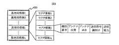
図1を用いて本発明において使用する基地局情報テーブルの実施例を説明する。同図において100が基地局情報テーブルである。このテーブルは、複数の基地局情報1乃至nを含んでいる。各基地局情報は一つ以上のセクタ情報を含んでいる。各セクタ情報はそれぞれ識別番号とセクタを形成するためのアンテナの位置と、アンテナの向きと、アンテナより送信されている送信符号を特定するための送信符号識別子とを含んでいる。
一般に基地局とは移動体通信のサービスを行う際に設置される電波源、主に地上局をいう。一つの基地局が複数のアンテナを持つことがあり、その場合それらのアンテナは異なる方向を向いており、各アンテナはセクタを形成している。厳密には、基地局の座標と、基地局に属する複数のアンテナの座標は全て異なる。例えば、各アンテナの位置は数センチ〜数メートル離れているのが通常である。テーブルのデータとしては、以下の実施例のように、基地局とそれに属するアンテナにそれぞれ異なる座標を与えても良い。また、基地局と各アンテナはそれと同じ座標を持つこととしてもよい。この場合、測位誤差は増えるが、テーブル規模は縮小し得るであろう。一つの基地に属するアンテナは、通常、回路の一部を共用しており、特に制御用のタイミング信号を形成する回路は共通のものとなるのが普通である。
次に図1および図2を用いて本発明による無線位置測定方法の実施例を説明する。図2において、STEP210は、基準基地局を決定するステップである。当該ステップにおいて、端末は基地局をサーチし、受信電力の最も大きな送信符号の送信元の基地局に同期する。そして、該基地局を基準基地局とする。通常、セルラシステムでは、基地局より制御情報が同報されており、該制御情報にはそのセクタの識別番号が含まれている。そのため、端末の同期獲得先となる送信元の基地局は一意に特定される。
【0016】
STEP220は、基地局情報テーブルを基準基地局からの距離が昇順となるよう、基地局情報単位でソートするステップである。ソートする際に、基準基地局の位置は、上記識別情報で特定される基地局情報テーブルに含まれるセクタ情報に記載のアンテナ位置とする。各基地局の位置は、それぞれの基地局情報に含まれている各セクタ情報のアンテナ位置をそれぞれの基地局情報内で平均した位置としてよい。あるいは、それぞれの基地局情報に含まれているセクタ情報から任意の一つのアンテナ位置を選択してもよい。
【0017】
STEP230は、上記テーブル内の各基地局情報について、各セクタ情報内のアンテナの向きと該アンテナから基準基地局への向きのなす角の余弦が降順となるようソートするステップである。
【0018】
STEP241は、上記テーブルにおいて、基地局情報単位で1乃至NALL番目までの各基地局情報について、該各基地局情報に含まれる各セクタに対する送信符号を、遅延プロファイル作成の対象として全て選択するステップである。なお、その際、選択された送信符号に対するアンテナ位置を保持しておく。
【0019】
STEP242は、上記テーブルにおいて、基地局情報単位で(NALL+1)乃至N1番目までの各基地局情報について、該各基地局情報に含まれるセクタに対する送信符号のうち、セクタ情報単位で1番目に記載の送信符号を、遅延プロファイル作成の対象として選択するステップである。なお、その際、選択された送信符号に対するアンテナ位置を保持しておく。
【0020】
STEP250は、上記選択した各送信符号について、それぞれ遅延プロファイルを作成するステップである。
STEP260は、上記作成した各遅延プロファイルを基にそれぞれの受信タイミングを推定し、上記STEP241乃至STEP242で保持した各送信元のアンテナ位置を用いて、該端末の位置を算出する。
受信信号を処理し、遅延プロファイルを作成する回路構成は、例えば本件出願人の特許出願2001-399979に開示されている。特許出願2001-399979の図2に示されるように、複数の受信信号を、1〜Nの並列化された回路で処理することにより、処理を高速に行うことができる。このような場合、測位に用いると決めたアンテナ(セクタ)単位で信号を処理することにより、より多くの信号源からの距離を同時に処理することができ、精度向上と高速処理を両立させることができる。図3を用いて、本発明による無線位置測定方法の第二の実施例を説明する。同図は図2に示したフローチャートにおいて、STEP242のステップと交換される部分である。図2に示した実施例と比較して特徴的な箇所は、STEP342である。
【0021】
STEP342は、先のステップまでにソートされた基地局情報テーブルにおいて、基地局情報単位で(NALL+1)乃至N2番目までの各基地局情報について、該各基地局情報に含まれるセクタに対する送信符号のうち、セクタ情報単位で2番目までに記載の送信符号を、遅延プロファイル作成の対象として選択するステップである。なお、その際、選択された送信符号に対するアンテナ位置を保持しておく。
【0022】
STEP343は、上記テーブルにおいて、基地局情報単位で(N2+1)乃至N1番目までの各基地局情報について、該各基地局情報に含まれるセクタに対する送信符号のうち、セクタ情報単位で1番目に記載の送信符号を、遅延プロファイル作成の対象として選択するステップである。なお、その際、選択された送信符号に対するアンテナ位置を保持しておく。
【0023】
本実施例で示した様に、一つの基地局情報から選択する送信符号の数を、ソート後の基地局情報テーブルにおける該基地局情報の順番に応じて、段階的に減少することも本発明の範疇にある。
【0024】
本発明による無線位置測定方法の第三の実施例を図4および図5を用いて説明する。
図4は、本実施例において使用する基地局情報テーブルの構造を示す。図1に示した基地局情報テーブルと比較して特徴的な箇所は、各セクタにおけるアンテナから放射されている信号の送信電力の記述を、該当するそれぞれのセクタ情報が含んでいることにある。
【0025】
図5は図2に示したフローチャートにおいて、STEP220乃至STEP230のステップと交換される部分である。図2に示した実施例と比較して特徴的な箇所は、STEP521乃至STEP523である。
STEP521は、基地局情報テーブルの各基地局情報をセクタ情報単位でソートするステップである。その際、各セクタ情報から求まる{推定受信電力}が降順となるように各基地局情報をセクタ情報単位でソートする。ここで、各セクタ情報から求まる{推定受信電力}とは、該セクタ情報で特定される送信アンテナより放射された信号(送信符号)が、端末の概略位置とした基準基地局の位置において、受信されるときの受信電力の推定値である。このような値は、送信アンテナより放射される信号電力に、伝搬損失と、放射方向によるアンテナ利得とを乗じることによって得られる。伝搬損失とアンテナ利得の算出例については例えば図11における距離伝搬損失の欄と送信アンテナ利得の欄とをそれぞれ参照されたい。なお、基準基地局に関する基地局情報については、伝搬損失を乗じる処理を省略し、STEP210で得られている識別情報で特定されるアンテナの向きを基準の向きとして、各{推定受信電力}を算出すればよい。
STEP522は、基地局情報テーブルの各基地局情報の各一番目のセクタ情報から求まる{推定受信電力}を各基地局情報の{代表推定受信電力}とするステップである。
STEP523は、各基地局情報の{代表推定受信電力}が降順となるよう基地局情報テーブルを基地局情報単位でソートするステップである。
【0026】
なお、上記伝搬損失は、基準基地局からの距離の二乗値もしくはそれ以上に比例する。そのため、各基地局の送信電力が同程度ならば、基地局情報テーブルは、およそ、基準基地局からの距離に近い順に、ソートされることになる。
ここでは、上記第二の実施例をTIA/EIA-95に準拠するセルラシステムへの適用例を図6乃至図8を用いて示す。
【0027】
図6〜8は基地局情報テーブルの構成例である。同図において、三行毎に太線で囲まれた部分が一つの基地局情報であり、各行はそれぞれの基地局情報に含まれる一つのセクタ情報を示す。識別番号には、TIA/EIA-95における例えばBASE_IDを設定する。あるいは、TIA/EIA-95におけるBASE_IDに加え、SID、NID、BAND_CLASSあるいはCDMA_FREQといったそれぞれのセクタを特定するためのパラメータ値を併記して設定してもよい。アンテナ位置には、該セクタを形成するために用いられる送信アンテナの位置を設定する。位置のフォーマットは、例えば、緯度・経度でもよいし、局所的な地域に限定可能なら平面直角座標系を用いてもよい。図6の例では平面直角座標系で、西から東への向きをY軸正方向、南から北への向きをX軸正方向として、アンテナの位置を表している。アンテナ向きには、該セクタを形成するために用いられる送信アンテナの向きを設定する。向きのフォーマットは、例えば、Y軸正方向を0°とし、反時計回りを正方向として設定する。送信符号識別子には、該セクタにおいて用いられている送信符号を特定するための識別子を、例えば、TIA/EIA-95におけるPILOT_PNを設定する。
【0028】
さて、STEP210において、端末が識別番号0501で特定される基地局を基準基地局としたものと仮定する。図6に示した基地局情報テーブルに対し、STEP220からSTEP230までの処理を行った後の基地局情報テーブルを図7に示す。続いて、NALL = 3、N2 = 8、N1 = 13と仮定すると、STEP241、STEP342およびSTEP343の処理を行った場合、遅延プロファイルを作成するために選択された送信符号を、セクタ情報も含め、選択順に、図8に示す。
【0029】
図9を用いて本発明による位置測定端末の実施例を説明する。この端末は、例えば携帯電話の端末を兼用するものとすることができる。その場合、901〜911はCDMA方式の端末が通常の通信動作を可能とする要素を示す。901は送受信を行うアンテナ、902は高周波信号とベースバンド信号との変換を行うRF部、903はディジタル信号をアナログ信号に変換するDA変換部、904はアナログ信号をディジタル信号に変換するAD変換部、905は変調信号に対してスペクトル拡散を行う拡散部、906はディジタル受信信号から制御チャネル信号および通信チャネル信号を取り出すために逆拡散を行う逆拡散部、907はディジタル受信信号からパイロットチャネル信号を取り出すために逆拡散を行う逆拡散部、908はメッセージを変調するための変調部、909はパイロット信号を参照して制御チャネルあるいは通信チャネル上のメッセージを取り出す復調部、910は受信メッセージあるいは送信するためのメッセージを蓄積するためのメモリを示す。
【0030】
CPU 911は呼制御、受信メッセージ解析、送信メッセージ生成を行う。911の一部、および912〜913は測位処理を可能とする要素を示す。CPU 911は上述の処理に加え、図2、図3あるいは図5に示した本発明による無線位置測定方法のフローに従い、相関演算部912の制御と、メモリ913に蓄積される複数の遅延プロファイルとメモリ910に蓄積される基地局情報テーブルとに基づいて該端末の位置を計算する。相関演算部912は逆拡散部907からの送信符号のタイミングを参照しCPU 911から指示される送信符号について遅延プロファイルを生成してメモリ913に出力する相関演算部を示す。遅延プロファイルの例は、例えば図13に示したようなものである。遅延プロファイルの作成方法については、例えば前述の特開2001-359140に記載がある。
【0031】
本発明による無線位置測定方法において、基地局情報テーブルをソートするステップと、送信符号を選択するステップとについては、端末の外部で処理してもよい。典型例としては、端末と無線回線及びネットワークを介して接続されるサーバーにおいて処理することができる。すなわち、STEP220、STEP230、STEP241、STEP242、STEP342、STEP343、STEP521乃至STEP523は、端末の外部のサーバーで処理してもよい。
【0032】
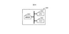
図10にその際のサーバーの構成を示す。サーバー1000は、基地局情報テーブルを蓄積するためのメモリ1001と、基地局情報テーブルをソートするステップと、送信符号を選択するステップとを実行するためのCPU1002と、セルラネットワークを介して、端末から基準基地局の識別番号を受信し、端末へ選択した送信符号識別子をセクタ情報も含めて送信するための通信部1003とを備える。このようなサーバーはPCなどにより実現できる。
【0033】
以上では信号の伝搬遅延時間に基づいて基地局と端末の距離を測定し、位置を検出する例について説明した。他の例として、端末が受信した信号の電界強度を元にして基地局からの距離を求め、同様に位置を測定する技術がある(例えば、特開平9−247737号参照)。本願発明はこのような技術にも適用可能である。具体的には本発明は、各基地局からの信号の受信電力に基づく位置検出方法にも適用される。例えば、各遅延プロファイルから得られる受信タイミングより、基地局からの伝搬距離をそれぞれ推定するのでなく、各遅延プロファイルから得られる受信電力より、基地局からの伝搬距離をそれぞれ推定し、これら各基地局からの伝搬距離と各基地局の位置とから端末の位置を決定する位置検出方法にも適用される。
【0034】
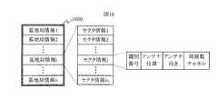
上述の様な各基地局からの信号の受信電力に基づく位置検出方法において、本発明はさらに別の応用例を与える。例えば、各基地局が異なる周波数チャネルを用いるセルラシステム場合には、図16の基地局情報テーブルと図15のフローとが適用される。
図16の基地局情報テーブルにおいて、図1に示した基地局情報テーブルと比較して特徴的な箇所は、各セクタにおける周波数チャネルの記述を、該当するそれぞれのセクタ情報が含んでいることにある。
【0035】
図15のフローにおいて、STEP1510は、基準基地局を決定するステップである。当該ステップにおいて、端末は基地局をサーチし、受信電力の最も大きな周波数チャネルの基地局を基準基地局とする。
STEP1520は、基地局情報テーブルを基準基地局からの距離が昇順となるよう、基地局情報単位でソートするステップである。
STEP1530は、上記テーブル内の各基地局情報について、各セクタ情報内のアンテナの向きと該アンテナから基準基地局への向きのなす角の余弦が降順となるようソートするステップである。
【0036】
STEP1541は、上記テーブルにおいて、基地局情報単位で1乃至NALL番目までの各基地局情報について、該各基地局情報に含まれる各セクタに対する周波数チャネルを、受信電力測定の対象として全て選択するステップである。なお、その際、選択された周波数チャネルに対するアンテナ位置を保持しておく。
【0037】
STEP1542は、上記テーブルにおいて、基地局情報単位で(NALL+1)乃至N1番目までの各基地局情報について、該各基地局情報に含まれるセクタに対する周波数チャネルのうち、セクタ情報単位で1番目に記載の周波数チャネルを、受信電力測定の対象として選択するステップである。なお、その際、選択された周波数チャネルに対するアンテナ位置を保持しておく。
【0038】
STEP1550は、上記選択した各周波数チャネルについて、それぞれ受信電力を測定するステップである。
STEP1560は、上記測定した各受信電力を基にそれぞれの伝搬距離を推定し、上記STEP1541乃至STEP1542で保持した各送信元のアンテナ位置を用いて、該端末の位置を算出する。
このように基地局が異なる周波数チャネルを用いるセルラシステム場合においても、本発明によれば、位置計算に利用可能な基地局の周波数チャネルを効率的に選択することが可能である。
【0039】
本発明の実施例による効果をシミュレーションにより示す。まず、シミュレーション諸元を図11に示す。本発明を適用すると、遅延プロファイルを作成するために図8に示された24種類の送信符号が選択され、その遅延プロファイルは送信符号の18種類について信号検出条件を満足する結果を得る。これら送信符号に対するアンテナ位置を用いてHDOP(水平精度低下率)を算出すると10.27を得る。
【0040】
これに対し、本発明を用いずに、例えば、遅延プロファイルを作成するための24種類の送信符号を、単純に、基準基地局からの距離の小さい順に、選択した場合、9種類の送信符号が信号検出条件を満足しない結果を得る。残りの15種類の送信符号に対するアンテナ位置を用いてHDOP(水平精度低下率)を算出すると本発明を適用したHDOPに比べ劣化した値11.47を得る。
【0041】
【発明の効果】
このように、本発明では、アンテナの向きを考慮して、遅延プロファイルを作成するための送信符号を選択するので、該送信符号の送信元が端末から離れていても、効率よく信号検出できる。さらに、これより、位置計算に用いることが可能な、場所の異なる基地局が増加するため、遅延プロアイル作成数が限定された状況においても、効果的に測位精度を向上することが可能となる。
【図面の簡単な説明】
【図1】本発明における基地局情報テーブルの実施例を示すフォーマット図である。
【図2】本発明による無線位置測定方法の実施例を示すフロー図である。
【図3】本発明による無線位置測定方法の第二の実施例における処理の一部を示すフロー図である。
【図4】本発明における基地局情報テーブルの別の実施例を示すフォーマット図である。
【図5】本発明による無線位置測定方法の第三の実施例における処理の一部を示すフロー図である。
【図6】本発明における基地局情報テーブルのTIA/EIA-95準拠のシステムへの適用例を示すテーブル図である。
【図7】STEP220、STEP230の処理を図6の基地局情報テーブルに適用した結果を示すテーブル図である。
【図8】STEP241、STEP342、STEP343の処理を図7の基地局情報テーブルに適用した結果を示すテーブル図である。
【図9】本発明による端末の実施例を示すブロック図である。
【図10】本発明によるサーバーの実施例を示すブロック図である。
【図11】本発明による効果を説明するために用いたシミュレーション諸元を示す表図である。
【図12】従来の広帯域の無線信号を使った端末の位置測定技術を示す概念図である。
【図13】遅延プロファイルの例示する波形図である。
【図14】基地局の指向性アンテナによりセクタが形成されることを説明するための平面図である。
【図15】本発明による無線位置測定方法の応用例を示すフロー図である。
【図16】本発明の応用例における基地局情報テーブルの実施例を示すフォーマット図である。
【図17】本発明の概念を示す平面図。
【図18】本発明の位置測定システムの全体構成図。
【符号の説明】
100,400:基地局情報テーブル、901:アンテナ、902:RF部、903:DA変換部、904:AD変換部、905:拡散部、906,907:逆拡散部、908:変調部、909:復調部、910,913:メモリ、911:CPU、912:相関演算部、1000:サーバー、1001:メモリ、1002:CPU、1003:通信部、1201:端末、1202,1203,1204:基地局、1205:GPS。[0001]
BACKGROUND OF THE INVENTION
The present invention relates to position measurement by radio, and more particularly to a technique suitable for a cellular base station as a signal source.
[0002]
[Prior art]
As a terminal position measurement technique using a broadband wireless signal, Japanese Patent Laid-Open No. 2001-359140 discloses a system using a CDMA (Code Division Multiple Access) signal.
The concept is shown in FIG. The
[0003]
FIG. 13 shows an example of a delay profile. The delay profile is obtained by calculating the correlation between the transmission code and the received signal. Since the time (timing) with high correlation indicates the signal reception timing, it is used for estimating the propagation time.
[0004]
If the propagation distance can be estimated for signals from three base stations that geometrically have different positions, the terminal position can be estimated by the principle of triangulation. Furthermore, if the propagation distance can be estimated for four or more base stations, the terminal position can be estimated with higher accuracy using, for example, the least square method.
Therefore, in order to specify the location of the terminal, it is preferable to create such a delay profile for transmission codes of at least three base stations having different locations.
In order to improve the estimation accuracy of the terminal position, it is preferable that many base stations existing in different places can be used. However, in order to create a delay profile for one transmission code, a large number of steps and a large amount of memory are required. Therefore, the number of transmission codes of the base station that can create a delay profile is limited from the viewpoint of circuit scale. This restriction becomes even more severe if the terminal is reduced in size and power consumption.
[0005]
By the way, a base station that can be used as a signal source generally forms a plurality of sector cells called sectors by directional antennas. Such a base station configuration is a normal configuration in a radio base station for mobile phones, for example.
An example is shown in FIG. Base station 1410
[0006]
[Problems to be solved by the invention]
Therefore, an object of the present invention is to use more base stations as base stations that are signal sources of signals to be created when creating a delay profile in terminal position measurement. Further, this is realized by a circuit having a small scale. At this time, selection of a transmission code for the sector of the base station becomes a problem.
[0007]
[Means for Solving the Problems]
The present invention relates to a radio position measurement method based on creation of a delay profile of a received signal, and a base station used for position measurement based on the position of the base station and the direction of each antenna of the base station forming each sector. The transmission code for each sector is selected.
Specifically, in a position measurement method in which signals transmitted from a plurality of antennas are received by a terminal and the position of the terminal is measured based on the received signals, the position is measured based on the position and orientation of the antenna. An antenna that is a transmission source of the signal is selected.
As a position measurement technique, for example, a delay profile of a received signal is created, and a terminal position is measured based on the delay profile. There is also a method of measuring the received power of a received signal and measuring the position of the terminal based on the received power value.
[0008]
Here, since the base station is provided with a plurality of antennas having different ordinary orientations, another aspect of the present invention is to treat a base station normally treated as a unit as a set of a plurality of antennas or sectors. is there.
FIG. 17 shows an example of this concept. The black square indicates the position of the position measuring terminal. Multiple circles indicate base stations. Each circle is divided into three equal parts and divided into three sectors. In the comparative example shown in FIG. 17, among signals (radio waves) transmitted from the base station, signals used for positioning are signals from the reference base station and its seven adjacent base stations. Seven base stations consist of 21 sectors, and the signals of each sector can be processed in parallel by 21 circuits.
[0009]
According to the example of Japanese Patent Application No. 2001-029560 filed earlier by the applicant of the present application, the signals of the three sectors of each base station are processed, but only one can be used for positioning. The signal belonging to the white part of the circle indicating the base station in FIG. 17 is processed by the circuit. On the other hand, in the present invention, the signal processed by the circuit is selected in units of sectors. Signals of 21 sectors are processed in parallel as in the past, but there are 13 base stations serving as signal transmission sources, and positioning is possible based on more positions than in the past.
[0010]
There are various possible procedures for antenna or base station selection.
(1) The position of an arbitrary base station (usually the closest or the strongest receiving base station) is used as a reference.
(2) For a base station that is at least a predetermined distance from the reference, a transmission code radiated from an antenna of the base station whose antenna is closest to the reference is selected.
(3) For a base station that is close to a predetermined distance from the reference, a transmission code radiated from all antennas forming the sector of the base station is selected.
[0011]
According to another aspect of the present invention, in a wireless position measurement method for measuring a position based on a received power of a signal from a base station, a base station that is a transmission source when measuring a received power of a signal from the base station A frequency position measurement method for determining a frequency channel for receiving a signal from a base station to be measured based on the position of the antenna and the direction of the antenna.
[0012]
FIG. 18 shows the overall configuration of a position measurement system using the present invention. The mobile terminal located on the left side includes a location LSI for performing position measurement. This terminal processes radio waves from a plurality of base station antennas. The base station is connected to a location information center including a location detection server via a network. The location information center may include a server that manages billing and authentication. It can also be connected to other ASPs that provide other application services.
[0013]
The mobile terminal is formed by an antenna that receives signals transmitted from a plurality of antennas to form a received signal, an RF circuit that converts a high-frequency signal and a baseband signal using the received signal as an input, and the RF circuit AD converter that converts the analog signal into a digital signal, a despreader that performs despreading to extract a pilot signal from the digital signal, and a plurality of delay profiles using the timing of the pilot signal obtained from the despreader And a control unit that selects a signal for which the delay profile is to be created based on the directions and coordinates of the plurality of antennas.
In addition, the position detection server receives signals transmitted from a plurality of antennas at a terminal, and is used in a position measurement system that measures the position of the terminal based on the received signals. And a storage device for storing a table for storing data relating to transmission codes, a CPU for extracting an antenna having a predetermined condition from the base station information table, and communication for transmitting data relating to the selected antenna to a terminal via a network Part.
The storage device for storing the antenna or base station data table and the selection means for selecting the antenna or base station satisfying a desired condition from the data table may be in either the terminal or the server. As long as they are connected by a network as shown in FIG. 18, the effect of the present invention can be achieved as long as data transfer is sufficiently fast regardless of which of these entities belongs.
[0014]
DETAILED DESCRIPTION OF THE INVENTION
The present invention relates to a method for creating a delay profile based on a position of a base station and an orientation of each antenna of the base station forming each sector, in a radio position measurement method based on creation of a delay profile of a received signal. The transmission code for the sector of the base station to be selected is selected. Hereinafter, specific examples of the present invention will be described with reference to the drawings.
[0015]
An embodiment of the base station information table used in the present invention will be described with reference to FIG. In the figure, 100 is a base station information table. This table includes a plurality of pieces of
In general, a base station refers to a radio wave source that is installed when a mobile communication service is provided, mainly a ground station. One base station may have a plurality of antennas, in which case the antennas are oriented in different directions, and each antenna forms a sector. Strictly speaking, the coordinates of the base station and the coordinates of a plurality of antennas belonging to the base station are all different. For example, the position of each antenna is usually several centimeters to several meters away. As the data of the table, different coordinates may be given to the base station and the antenna belonging to it as in the following embodiment. Also, the base station and each antenna may have the same coordinates. In this case, the positioning error increases, but the table size may be reduced. An antenna belonging to one base usually shares a part of a circuit, and in particular, a circuit that forms a timing signal for control is usually common.
Next, an embodiment of the wireless position measuring method according to the present invention will be described with reference to FIGS. In FIG. 2,
[0016]
[0017]
[0018]
STEP241 is 1 to N in the base station information unit in the above table.ALL This is a step of selecting all the transmission codes for each sector included in each base station information as targets for delay profile creation for each base station information up to the th. At that time, the antenna position for the selected transmission code is held.
[0019]
STEP242 is the base station information unit (NALL +1) through N1 This is a step of selecting the first transmission code for each sector information unit as a delay profile creation target among the transmission codes for the sectors included in the base station information for each of the first base station information. At that time, the antenna position for the selected transmission code is held.
[0020]
A circuit configuration for processing a received signal and creating a delay profile is disclosed in, for example, the applicant's patent application 2001-399979. As shown in FIG. 2 of the patent application 2001-399979, processing can be performed at high speed by processing a plurality of received signals with 1 to N parallel circuits. In such a case, by processing the signal in units of antennas (sectors) determined to be used for positioning, distances from a larger number of signal sources can be processed at the same time, and both accuracy improvement and high-speed processing can be achieved at the same time. it can. A second embodiment of the wireless position measuring method according to the present invention will be described with reference to FIG. This figure is a part exchanged with the
[0021]
STEP342 is (N) in base station information units in the base station information table sorted up to the previous step.ALL +1) to N2 This is a step of selecting the transmission codes described up to the second in sector information units among the transmission codes for the sectors included in each base station information as the targets for delay profile creation. At that time, the antenna position for the selected transmission code is held.
[0022]
STEP343 is the base station information unit (N2 +1) to N1 This is a step of selecting the first transmission code for each sector information unit as a delay profile creation target among the transmission codes for the sectors included in the base station information for each of the first base station information. At that time, the antenna position for the selected transmission code is held.
[0023]
As shown in the present embodiment, the number of transmission codes to be selected from one base station information can be decreased stepwise according to the order of the base station information in the sorted base station information table. It is in the category.
[0024]
A third embodiment of the wireless position measuring method according to the present invention will be described with reference to FIGS.
FIG. 4 shows the structure of the base station information table used in this embodiment. A characteristic point compared with the base station information table shown in FIG. 1 is that each corresponding sector information includes a description of transmission power of a signal radiated from an antenna in each sector.
[0025]
FIG. 5 is a part exchanged with the steps of STEP220 to STEP230 in the flowchart shown in FIG.
STEP 522 is a step in which {estimated received power} obtained from each first sector information of each base station information in the base station information table is set as {representative estimated received power} of each base station information.
[0026]
The propagation loss is proportional to the square value of the distance from the reference base station or more. Therefore, if the transmission power of each base station is approximately the same, the base station information table is sorted in the order of the distance from the reference base station.
Here, an application example of the second embodiment to a cellular system compliant with TIA / EIA-95 will be described with reference to FIGS.
[0027]
6 to 8 are configuration examples of the base station information table. In the same figure, a portion surrounded by a thick line every three rows is one base station information, and each row shows one sector information included in each base station information. For example, BASE_ID in TIA / EIA-95 is set as the identification number. Alternatively, in addition to BASE_ID in TIA / EIA-95, parameter values for specifying each sector such as SID, NID, BAND_CLASS, or CDMA_FREQ may be set together. As the antenna position, the position of the transmission antenna used to form the sector is set. The format of the position may be, for example, latitude / longitude, or a plane rectangular coordinate system may be used if it can be limited to a local area. In the example of FIG. 6, the antenna position is represented in a plane rectangular coordinate system with the direction from west to east as the Y axis positive direction and the direction from south to north as the X axis positive direction. As the antenna direction, the direction of the transmission antenna used for forming the sector is set. The orientation format is set, for example, with the Y-axis positive direction being 0 ° and the counterclockwise direction being the positive direction. In the transmission code identifier, an identifier for specifying the transmission code used in the sector, for example, PILOT_PN in TIA / EIA-95 is set.
[0028]
Now, in STEP210, it is assumed that the base station identified by the
[0029]
An embodiment of the position measuring terminal according to the present invention will be described with reference to FIG. This terminal can also be used as, for example, a mobile phone terminal. In this case,
[0030]
The CPU 911 performs call control, received message analysis, and transmission message generation. A part of 911 and elements 912 to 913 indicate elements that enable positioning processing. In addition to the above processing, the CPU 911 controls the correlation calculation unit 912 and a plurality of delay profiles stored in the
[0031]
In the wireless position measurement method according to the present invention, the step of sorting the base station information table and the step of selecting a transmission code may be processed outside the terminal. As a typical example, processing can be performed in a server connected to a terminal via a wireless line and a network. That is, STEP220, STEP230, STEP241, STEP242, STEP342, STEP343, and STEP521 to STEP523 may be processed by a server outside the terminal.
[0032]
FIG. 10 shows the configuration of the server at that time. The
[0033]
In the above, the example which measured the distance of a base station and a terminal based on the propagation delay time of a signal, and detected a position was demonstrated. As another example, there is a technique for obtaining the distance from the base station based on the electric field strength of the signal received by the terminal and measuring the position in the same manner (see, for example, JP-A-9-247737). The present invention is also applicable to such a technique. Specifically, the present invention is also applied to a position detection method based on received power of signals from each base station. For example, instead of estimating the propagation distance from the base station from the reception timing obtained from each delay profile, the propagation distance from the base station is estimated from the received power obtained from each delay profile, respectively. This is also applied to a position detection method for determining the position of the terminal from the propagation distance from the terminal and the position of each base station.
[0034]
In the position detection method based on the received power of the signal from each base station as described above, the present invention provides still another application example. For example, in the case of a cellular system in which each base station uses different frequency channels, the base station information table of FIG. 16 and the flow of FIG. 15 are applied.
In the base station information table of FIG. 16, a characteristic point compared to the base station information table shown in FIG. 1 is that each corresponding sector information includes a description of the frequency channel in each sector. .
[0035]
In the flow of FIG. 15,
[0036]
STEP1541 is 1 to N in the base station information unit in the above table.ALL This is a step of selecting all frequency channels for each sector included in each base station information as reception power measurement targets for each base station information up to the th. At that time, the antenna position for the selected frequency channel is maintained.
[0037]
STEP1542 is the base station information unit (NALL +1) through N1 This is a step of selecting the first frequency channel described in units of sector information among the frequency channels for the sectors included in each base station information as reception power measurement targets for each base station information up to the first. At that time, the antenna position for the selected frequency channel is maintained.
[0038]
Thus, even in the case of a cellular system in which base stations use different frequency channels, according to the present invention, it is possible to efficiently select a frequency channel of a base station that can be used for position calculation.
[0039]
The effect by the Example of this invention is shown by simulation. First, simulation parameters are shown in FIG. When the present invention is applied, 24 types of transmission codes shown in FIG. 8 are selected to create a delay profile, and the delay profile obtains a result that satisfies the signal detection condition for 18 types of transmission codes. If HDOP (horizontal accuracy reduction rate) is calculated using the antenna position for these transmission codes, 10.27 is obtained.
[0040]
On the other hand, without using the present invention, for example, when 24 types of transmission codes for creating a delay profile are simply selected in ascending order of distance from the reference base station, 9 types of transmission codes are obtained. A result that does not satisfy the signal detection condition is obtained. When HDOP (horizontal accuracy reduction rate) is calculated using the antenna positions for the remaining 15 types of transmission codes, a degraded value 11.47 is obtained as compared with HDOP to which the present invention is applied.
[0041]
【The invention's effect】
Thus, in the present invention, since the transmission code for creating the delay profile is selected in consideration of the antenna direction, signal detection can be performed efficiently even if the transmission code source is away from the terminal. Furthermore, since the number of base stations with different locations that can be used for position calculation increases, it is possible to effectively improve positioning accuracy even in a situation where the number of delay pile creations is limited.
[Brief description of the drawings]
FIG. 1 is a format diagram showing an embodiment of a base station information table in the present invention.
FIG. 2 is a flowchart showing an embodiment of a wireless position measurement method according to the present invention.
FIG. 3 is a flowchart showing a part of processing in the second embodiment of the wireless position measuring method according to the present invention;
FIG. 4 is a format diagram showing another embodiment of the base station information table in the present invention.
FIG. 5 is a flowchart showing a part of the processing in the third embodiment of the wireless position measuring method according to the present invention.
FIG. 6 is a table showing an application example of a base station information table in the present invention to a TIA / EIA-95 compliant system.
7 is a table showing the result of applying the processing of
8 is a table showing the results of applying the processing of STEP241, STEP342, and STEP343 to the base station information table of FIG.
FIG. 9 is a block diagram showing an embodiment of a terminal according to the present invention.
FIG. 10 is a block diagram showing an embodiment of a server according to the present invention.
FIG. 11 is a table showing simulation specifications used for explaining the effects of the present invention.
FIG. 12 is a conceptual diagram illustrating a conventional terminal position measurement technique using a broadband wireless signal.
FIG. 13 is a waveform diagram illustrating a delay profile.
FIG. 14 is a plan view for explaining that a sector is formed by a directional antenna of a base station.
FIG. 15 is a flowchart showing an application example of the wireless position measurement method according to the present invention.
FIG. 16 is a format diagram showing an example of a base station information table in an application example of the present invention.
FIG. 17 is a plan view showing the concept of the present invention.
FIG. 18 is an overall configuration diagram of a position measurement system according to the present invention.
[Explanation of symbols]
100, 400: base station information table, 901: antenna, 902: RF unit, 903: DA conversion unit, 904: AD conversion unit, 905: spreading unit, 906, 907: despreading unit, 908: modulation unit, 909: Demodulator, 910, 913: Memory, 911: CPU, 912: Correlation calculator, 1000: Server, 1001: Memory, 1002: CPU, 1003: Communication unit, 1201: Terminal, 1202, 1203, 1204: Base station, 1205 :GPS.
Claims (5)
Translated fromJapanese上記基地局のうち任意の基地局の位置を基準として、Based on the position of any base station among the above base stations,
該基準から所定以上遠距離にある基地局については、該基地局のセクタを形成する上記アンテナのうち、向きが上記基準への向きに最も近いアンテナより放射される送信符号に基づいて上記端末の位置を測定し、For a base station that is more than a predetermined distance from the reference, the terminal of the terminal is based on a transmission code radiated from the antenna that forms the sector of the base station whose direction is closest to the reference. Measure the position,
該基準から所定以上近距離にある基地局については、該基地局のセクタを形成する全てのアンテナより放射される送信符号に基づいて上記端末の位置を測定することを特徴とする位置測定方法。A position measuring method for measuring the position of the terminal for a base station at a short distance from the reference based on a transmission code radiated from all antennas forming a sector of the base station.
上記任意の基地局は、上記受信した電力が最大のもの、または端末との距離が最小のものを基準とすることを特徴とする位置測定方法。The position measurement method according to any one of claims 1 to 4, wherein the arbitrary base station is based on the received power having the maximum power or the minimum distance from the terminal.
上記遅延プロファイル作成の対象として各基地局の送信符号を選択する際に、When selecting the transmission code of each base station as the target of the delay profile creation,
各基地局の上記基準からの距離の増加に応じて、それぞれの基地局から選択する送信符号の数を段階的に減少していくことを特徴とする位置測定方法。A position measuring method, wherein the number of transmission codes to be selected from each base station is decreased stepwise as the distance from each base station increases from the reference.
上記受信信号の遅延プロファイルを作成する際に、上記端末の概略位置における推定受信電力が降順となるよう、該遅延プロファイル作成の対象とする基地局を決定することを特徴とする位置測定方法。A position measurement method comprising: determining a base station for which a delay profile is to be created so that the estimated received power at the approximate position of the terminal is in descending order when creating the delay profile of the received signal.
上記複数のアンテナの座標、指向性、及び送信符号に関するデータを記憶する基地局情報テーブルを蓄積する記憶装置と、A storage device for storing a base station information table for storing data on the coordinates, directivity, and transmission code of the plurality of antennas;
該基地局情報テーブルから所定条件を有するアンテナを抽出するCPUと、A CPU for extracting an antenna having a predetermined condition from the base station information table;
ネットワークを介して上記端末へ選択したアンテナに関するデータを送信する通信部とを有し、A communication unit that transmits data related to the selected antenna to the terminal via the network,
上記基地局情報テーブルから、アンテナの位置と向きとに基づいてアンテナを抽出することを特徴とするサーバー。A server, wherein an antenna is extracted from the base station information table based on an antenna position and orientation.
Priority Applications (5)
| Application Number | Priority Date | Filing Date | Title |
|---|---|---|---|
| JP2002202055AJP3972755B2 (en) | 2002-07-11 | 2002-07-11 | Position measuring method, and terminal device and server used therefor |
| CNB021571945ACN100486389C (en) | 2002-07-11 | 2002-12-19 | Position mensuration method |
| US10/340,748US7110775B2 (en) | 2002-07-11 | 2003-01-13 | Position calculation method and a mobile terminal and a server therefor |
| EP03001284AEP1380851B1 (en) | 2002-07-11 | 2003-01-22 | Position calculation method of a mobile terminal |
| DE60327022TDE60327022D1 (en) | 2002-07-11 | 2003-01-22 | Location calculation method |
Applications Claiming Priority (1)
| Application Number | Priority Date | Filing Date | Title |
|---|---|---|---|
| JP2002202055AJP3972755B2 (en) | 2002-07-11 | 2002-07-11 | Position measuring method, and terminal device and server used therefor |
Publications (2)
| Publication Number | Publication Date |
|---|---|
| JP2004048307A JP2004048307A (en) | 2004-02-12 |
| JP3972755B2true JP3972755B2 (en) | 2007-09-05 |
Family
ID=29728489
Family Applications (1)
| Application Number | Title | Priority Date | Filing Date |
|---|---|---|---|
| JP2002202055AExpired - LifetimeJP3972755B2 (en) | 2002-07-11 | 2002-07-11 | Position measuring method, and terminal device and server used therefor |
Country Status (5)
| Country | Link |
|---|---|
| US (1) | US7110775B2 (en) |
| EP (1) | EP1380851B1 (en) |
| JP (1) | JP3972755B2 (en) |
| CN (1) | CN100486389C (en) |
| DE (1) | DE60327022D1 (en) |
Families Citing this family (37)
| Publication number | Priority date | Publication date | Assignee | Title |
|---|---|---|---|---|
| CN1198419C (en)* | 2003-01-16 | 2005-04-20 | 大唐移动通信设备有限公司 | Control method based on power of down doing guidance time slot |
| JP2004282643A (en)* | 2003-03-18 | 2004-10-07 | Hitachi Ltd | Radio base station and radio base station control method |
| US7640024B2 (en)* | 2003-12-30 | 2009-12-29 | Symbol Technologies, Inc. | Location tracking using directional antennas combined with signal strength measurements |
| JP4458247B2 (en)* | 2004-05-12 | 2010-04-28 | 日本電気株式会社 | Radio base station apparatus setting system and radio base station apparatus setting method |
| JP4609231B2 (en)* | 2005-08-05 | 2011-01-12 | 株式会社日立製作所 | Wireless position detection method and system |
| US8611305B2 (en) | 2005-08-22 | 2013-12-17 | Qualcomm Incorporated | Interference cancellation for wireless communications |
| US9071344B2 (en) | 2005-08-22 | 2015-06-30 | Qualcomm Incorporated | Reverse link interference cancellation |
| CN100407870C (en)* | 2005-08-31 | 2008-07-30 | 中兴通讯股份有限公司 | Method for Locating Mobile Terminals Using Distributed Antennas |
| US8488792B2 (en)* | 2005-10-26 | 2013-07-16 | Hewlett-Packard Development Company, L.P. | Wireless communications validation system and method |
| US8089881B2 (en) | 2006-03-03 | 2012-01-03 | Qualcomm Incorporated | Method and apparatus for increasing spectrum use efficiency in a mesh network |
| US7860518B2 (en) | 2006-11-17 | 2010-12-28 | Alcatel-Lucent Usa Inc. | Locating a mobile station inside a building |
| WO2008063489A2 (en)* | 2006-11-17 | 2008-05-29 | Lucent Technologies, Inc. | Locating a mobile station inside a building |
| JP4407691B2 (en)* | 2006-11-20 | 2010-02-03 | ソニー株式会社 | COMMUNICATION DEVICE, COMMUNICATION DEVICE PROTECTION METHOD, AND PROGRAM |
| ES2797393T3 (en) | 2007-05-01 | 2020-12-02 | Qualcomm Inc | Position location for wireless communication systems |
| US8514988B2 (en) | 2007-05-18 | 2013-08-20 | Qualcomm Incorporated | Enhanced pilot signal receiver |
| JP4843625B2 (en)* | 2008-01-24 | 2011-12-21 | 株式会社東芝 | Wireless communication system, wireless base station control device, and program for wireless base station control device |
| US8620339B2 (en)* | 2008-03-31 | 2013-12-31 | Verizon Patent And Licensing Inc. | System and method for providing quality of service mapping |
| US20100046660A1 (en) | 2008-05-13 | 2010-02-25 | Qualcomm Incorporated | Interference cancellation under non-stationary conditions |
| US8995417B2 (en) | 2008-06-09 | 2015-03-31 | Qualcomm Incorporated | Increasing capacity in wireless communication |
| US9237515B2 (en) | 2008-08-01 | 2016-01-12 | Qualcomm Incorporated | Successive detection and cancellation for cell pilot detection |
| US9277487B2 (en)* | 2008-08-01 | 2016-03-01 | Qualcomm Incorporated | Cell detection with interference cancellation |
| US8509293B2 (en) | 2008-08-19 | 2013-08-13 | Qualcomm Incorporated | Semi-coherent timing propagation for GERAN multislot configurations |
| US8503591B2 (en) | 2008-08-19 | 2013-08-06 | Qualcomm Incorporated | Enhanced geran receiver using channel input beamforming |
| JP5435971B2 (en)* | 2009-01-29 | 2014-03-05 | キヤノン株式会社 | Communication device |
| US9160577B2 (en) | 2009-04-30 | 2015-10-13 | Qualcomm Incorporated | Hybrid SAIC receiver |
| US8787509B2 (en) | 2009-06-04 | 2014-07-22 | Qualcomm Incorporated | Iterative interference cancellation receiver |
| US8831149B2 (en) | 2009-09-03 | 2014-09-09 | Qualcomm Incorporated | Symbol estimation methods and apparatuses |
| US8619928B2 (en) | 2009-09-03 | 2013-12-31 | Qualcomm Incorporated | Multi-stage interference suppression |
| US9509452B2 (en) | 2009-11-27 | 2016-11-29 | Qualcomm Incorporated | Increasing capacity in wireless communications |
| JP2013512593A (en) | 2009-11-27 | 2013-04-11 | クゥアルコム・インコーポレイテッド | Capacity increase in wireless communication |
| US8467309B2 (en)* | 2009-12-23 | 2013-06-18 | Verizon Patent And Licensing Inc. | Packet based location provisioning in wireless networks |
| EP2604079A2 (en)* | 2010-08-11 | 2013-06-19 | Telefonaktiebolaget LM Ericsson (publ) | Methods of providing cell grouping for positioning and related networks and devices |
| US8548493B2 (en)* | 2011-04-14 | 2013-10-01 | Navteq B.V. | Location tracking |
| US10129929B2 (en)* | 2011-07-24 | 2018-11-13 | Ethertronics, Inc. | Antennas configured for self-learning algorithms and related methods |
| CN102858010B (en)* | 2012-09-04 | 2015-02-04 | 大唐移动通信设备有限公司 | Positioning method and device for mobile terminal |
| CN107408976A (en)* | 2015-03-09 | 2017-11-28 | 威尔逊电子有限责任公司 | Signal Booster for Steerable Antenna Systems |
| CN105392195A (en)* | 2015-11-27 | 2016-03-09 | 上海斐讯数据通信技术有限公司 | Wireless access point device and terminal positioning method and system |
Family Cites Families (25)
| Publication number | Priority date | Publication date | Assignee | Title |
|---|---|---|---|---|
| JP3393417B2 (en) | 1993-12-22 | 2003-04-07 | ソニー株式会社 | Positioning system |
| JPH09247737A (en) | 1996-03-05 | 1997-09-19 | Rookasu:Kk | Location information detection system |
| US6154657A (en)* | 1997-10-21 | 2000-11-28 | Telefonaktiebolaget Lm Ericsson | Smart subdivision of base station candidates for position location accuracy |
| FI105597B (en)* | 1997-12-11 | 2000-09-15 | Nokia Networks Oy | Location procedure and location arrangement |
| US6353412B1 (en)* | 1998-03-17 | 2002-03-05 | Qualcomm, Incorporated | Method and apparatus for determining position location using reduced number of GPS satellites and synchronized and unsynchronized base stations |
| AU751799B2 (en)* | 1998-04-08 | 2002-08-29 | Telefonaktiebolaget Lm Ericsson (Publ) | Method and system for determining the position of a mobile terminal in a CDMA mobile communications system |
| US6246884B1 (en)* | 1998-08-19 | 2001-06-12 | Sigmaone Communications Corporation | System and method for measuring and locating a mobile station signal in a wireless communication system |
| US6496701B1 (en)* | 1998-08-25 | 2002-12-17 | Lucent Technologies Inc. | Pattern-recognition-based geolocation |
| KR100322001B1 (en)* | 1998-09-16 | 2002-06-22 | 윤종용 | Device and method for measuring position of mobile station in mobile communication system |
| GB9827989D0 (en)* | 1998-12-19 | 1999-02-10 | Koninkl Philips Electronics Nv | Location beacon system |
| WO2000075684A1 (en)* | 1999-06-04 | 2000-12-14 | Hitachi, Ltd. | Positioning device using cellular communication |
| CN1141855C (en)* | 1999-06-26 | 2004-03-10 | 深圳市中兴通讯股份有限公司 | Method for locating mobile terminal |
| US6282427B1 (en)* | 1999-07-14 | 2001-08-28 | Telefonaktiebolaget L M Ericsson (Publ) | Selection of location measurement units for determining the position of a mobile communication station |
| JP3573039B2 (en) | 1999-12-10 | 2004-10-06 | 株式会社日立製作所 | Wireless terminal position measuring method, terminal device using the same, and terminal position management station device |
| JP2001174537A (en)* | 1999-12-21 | 2001-06-29 | Hitachi Ltd | Wireless terminal position measuring method and terminal device using the same |
| JP3573052B2 (en)* | 2000-02-22 | 2004-10-06 | 株式会社日立製作所 | Wireless terminal position measurement device |
| JP2001268622A (en)* | 2000-03-17 | 2001-09-28 | Mitsubishi Electric Corp | Mobile station current position recognition method and current position recognition device, and mobile station and base station thereof |
| US6389291B1 (en)* | 2000-08-14 | 2002-05-14 | Sirf Technology | Multi-mode global positioning system for use with wireless networks |
| JP3740953B2 (en)* | 2000-06-13 | 2006-02-01 | 株式会社日立製作所 | Wireless position measuring terminal and wireless position measuring system |
| JP2002040121A (en)* | 2000-07-19 | 2002-02-06 | Fujitsu Ltd | Mobile communication system and mobile station position detection method |
| US20020025822A1 (en)* | 2000-08-18 | 2002-02-28 | Hunzinger Jason F. | Resolving ambiguous sector-level location and determining mobile location |
| JP2002077976A (en)* | 2000-09-05 | 2002-03-15 | Nippon Telegr & Teleph Corp <Ntt> | Position detection method, position detection system and mobile station |
| JP3547412B2 (en)* | 2001-07-24 | 2004-07-28 | 株式会社日立製作所 | Wireless terminal device and positioning system |
| US6912395B2 (en)* | 2001-09-25 | 2005-06-28 | Motorola, Inc. | Network and method for monitoring location capabilities of a mobile station |
| US20030125045A1 (en)* | 2001-12-27 | 2003-07-03 | Riley Wyatt Thomas | Creating and using base station almanac information in a wireless communication system having a position location capability |
- 2002
- 2002-07-11JPJP2002202055Apatent/JP3972755B2/ennot_activeExpired - Lifetime
- 2002-12-19CNCNB021571945Apatent/CN100486389C/ennot_activeExpired - Lifetime
- 2003
- 2003-01-13USUS10/340,748patent/US7110775B2/ennot_activeExpired - Lifetime
- 2003-01-22EPEP03001284Apatent/EP1380851B1/ennot_activeExpired - Lifetime
- 2003-01-22DEDE60327022Tpatent/DE60327022D1/ennot_activeExpired - Lifetime
Also Published As
| Publication number | Publication date |
|---|---|
| EP1380851A1 (en) | 2004-01-14 |
| EP1380851B1 (en) | 2009-04-08 |
| US20040203913A1 (en) | 2004-10-14 |
| CN1468023A (en) | 2004-01-14 |
| US7110775B2 (en) | 2006-09-19 |
| CN100486389C (en) | 2009-05-06 |
| JP2004048307A (en) | 2004-02-12 |
| DE60327022D1 (en) | 2009-05-20 |
Similar Documents
| Publication | Publication Date | Title |
|---|---|---|
| JP3972755B2 (en) | Position measuring method, and terminal device and server used therefor | |
| US7974633B2 (en) | System and method for single sensor geolocation | |
| Laitinen et al. | Database correlation method for GSM location | |
| US7123924B2 (en) | Method and system for determining the speed and position of a mobile unit | |
| CN101965050B (en) | Method and apparatus for estimating location of a wireless station using multi-beam transmission | |
| US8401570B2 (en) | LTE fingerprinting positioning references for other cellular systems | |
| CN103945331B (en) | A kind of localization method for the angle estimation that using WIFI field strength leave away | |
| CN101091400A (en) | Wireless Terminal Positioning Using Apparatus and Method Applying Carrier Diversity | |
| US20070202885A1 (en) | Method For Sparse Network Deployment Accuracy Enhancements | |
| US9408026B2 (en) | Methods and arrangements for positioning in wireless communications systems | |
| US20040023671A1 (en) | Method for enhanced mobile assisted positioning | |
| JP2001174537A (en) | Wireless terminal position measuring method and terminal device using the same | |
| CN102349338A (en) | Method and arrangement in a wireless communication system | |
| JP2000244967A (en) | MOBILE COMMUNICATION SYSTEM, MOBILE MACHINE AND BASE STATION COMPOSING THE SYSTEM, AND METHOD OF DETECTING POSITION OF MOBILE MACHINE IN THE SYSTEM | |
| US8116789B2 (en) | Terminal positioning technique | |
| WO2009084859A2 (en) | Time-difference estimation method for location based services in a cellular network | |
| CN103649769A (en) | Method and apparatus for geo-locating mobile station | |
| EP2484129B1 (en) | Lte fingerprinting positioning references for other cellular systems | |
| WO2003071303A1 (en) | Method for positioning of mobile stations | |
| CN115039422B (en) | Method, mobile station and computer readable medium for anonymously collecting directional transmissions | |
| KR20120030670A (en) | Method for estimating azimuth, apparatus and computer-readable recording medium with program therefor | |
| KR20060096096A (en) | Estimation of the location of the wireless mobile device relative to one or more base stations | |
| CN105093174B (en) | A kind of location algorithm based on the 2.5G wireless network signal profits and losses | |
| Lin et al. | Robust mobile location estimation based on signal attenuation for cellular communication systems | |
| CN115278876B (en) | Method for co-positioning between 5G network and UWB |
Legal Events
| Date | Code | Title | Description |
|---|---|---|---|
| A621 | Written request for application examination | Free format text:JAPANESE INTERMEDIATE CODE: A621 Effective date:20041125 | |
| RD01 | Notification of change of attorney | Free format text:JAPANESE INTERMEDIATE CODE: A7421 Effective date:20060419 | |
| A977 | Report on retrieval | Free format text:JAPANESE INTERMEDIATE CODE: A971007 Effective date:20060816 | |
| A131 | Notification of reasons for refusal | Free format text:JAPANESE INTERMEDIATE CODE: A131 Effective date:20060822 | |
| A521 | Request for written amendment filed | Free format text:JAPANESE INTERMEDIATE CODE: A523 Effective date:20061023 | |
| TRDD | Decision of grant or rejection written | ||
| A01 | Written decision to grant a patent or to grant a registration (utility model) | Free format text:JAPANESE INTERMEDIATE CODE: A01 Effective date:20070522 | |
| A61 | First payment of annual fees (during grant procedure) | Free format text:JAPANESE INTERMEDIATE CODE: A61 Effective date:20070604 | |
| R151 | Written notification of patent or utility model registration | Ref document number:3972755 Country of ref document:JP Free format text:JAPANESE INTERMEDIATE CODE: R151 | |
| FPAY | Renewal fee payment (event date is renewal date of database) | Free format text:PAYMENT UNTIL: 20100622 Year of fee payment:3 | |
| FPAY | Renewal fee payment (event date is renewal date of database) | Free format text:PAYMENT UNTIL: 20100622 Year of fee payment:3 | |
| FPAY | Renewal fee payment (event date is renewal date of database) | Free format text:PAYMENT UNTIL: 20110622 Year of fee payment:4 | |
| FPAY | Renewal fee payment (event date is renewal date of database) | Free format text:PAYMENT UNTIL: 20110622 Year of fee payment:4 | |
| FPAY | Renewal fee payment (event date is renewal date of database) | Free format text:PAYMENT UNTIL: 20120622 Year of fee payment:5 | |
| FPAY | Renewal fee payment (event date is renewal date of database) | Free format text:PAYMENT UNTIL: 20120622 Year of fee payment:5 | |
| FPAY | Renewal fee payment (event date is renewal date of database) | Free format text:PAYMENT UNTIL: 20130622 Year of fee payment:6 | |
| S111 | Request for change of ownership or part of ownership | Free format text:JAPANESE INTERMEDIATE CODE: R313111 | |
| R350 | Written notification of registration of transfer | Free format text:JAPANESE INTERMEDIATE CODE: R350 | |
| S111 | Request for change of ownership or part of ownership | Free format text:JAPANESE INTERMEDIATE CODE: R313111 | |
| R350 | Written notification of registration of transfer | Free format text:JAPANESE INTERMEDIATE CODE: R350 | |
| R250 | Receipt of annual fees | Free format text:JAPANESE INTERMEDIATE CODE: R250 | |
| R250 | Receipt of annual fees | Free format text:JAPANESE INTERMEDIATE CODE: R250 | |
| R250 | Receipt of annual fees | Free format text:JAPANESE INTERMEDIATE CODE: R250 | |
| R250 | Receipt of annual fees | Free format text:JAPANESE INTERMEDIATE CODE: R250 | |
| S111 | Request for change of ownership or part of ownership | Free format text:JAPANESE INTERMEDIATE CODE: R313111 | |
| R350 | Written notification of registration of transfer | Free format text:JAPANESE INTERMEDIATE CODE: R350 | |
| R250 | Receipt of annual fees | Free format text:JAPANESE INTERMEDIATE CODE: R250 | |
| EXPY | Cancellation because of completion of term |