JP3972063B2 - Quantitative analysis method and quantitative analysis apparatus using sensor - Google Patents
Quantitative analysis method and quantitative analysis apparatus using sensorDownload PDFInfo
- Publication number
- JP3972063B2 JP3972063B2JP2002557999AJP2002557999AJP3972063B2JP 3972063 B2JP3972063 B2JP 3972063B2JP 2002557999 AJP2002557999 AJP 2002557999AJP 2002557999 AJP2002557999 AJP 2002557999AJP 3972063 B2JP3972063 B2JP 3972063B2
- Authority
- JP
- Japan
- Prior art keywords
- electrode
- insufficient
- reagent layer
- sample liquid
- predetermined time
- Prior art date
- Legal status (The legal status is an assumption and is not a legal conclusion. Google has not performed a legal analysis and makes no representation as to the accuracy of the status listed.)
- Expired - Fee Related
Links
- 238000004445quantitative analysisMethods0.000titleclaimsdescription52
- 238000000034methodMethods0.000titleclaimsdescription39
- 239000003153chemical reaction reagentSubstances0.000claimsdescription149
- 238000005259measurementMethods0.000claimsdescription108
- 239000007788liquidSubstances0.000claimsdescription89
- 239000000523sampleSubstances0.000claimsdescription89
- 239000012488sample solutionSubstances0.000claimsdescription58
- 238000012360testing methodMethods0.000claimsdescription41
- 238000004364calculation methodMethods0.000claimsdescription13
- 238000009795derivationMethods0.000claimsdescription9
- 230000000694effectsEffects0.000claimsdescription6
- 239000008280bloodSubstances0.000description104
- 210000004369bloodAnatomy0.000description104
- WQZGKKKJIJFFOK-GASJEMHNSA-NGlucoseNatural productsOC[C@H]1OC(O)[C@H](O)[C@@H](O)[C@@H]1OWQZGKKKJIJFFOK-GASJEMHNSA-N0.000description28
- 239000008103glucoseSubstances0.000description28
- 238000006243chemical reactionMethods0.000description16
- 238000001514detection methodMethods0.000description14
- 239000000758substrateSubstances0.000description12
- 239000007864aqueous solutionSubstances0.000description7
- WPYMKLBDIGXBTP-UHFFFAOYSA-Nbenzoic acidChemical compoundOC(=O)C1=CC=CC=C1WPYMKLBDIGXBTP-UHFFFAOYSA-N0.000description6
- 238000002474experimental methodMethods0.000description5
- 108010015776Glucose oxidaseProteins0.000description4
- 239000004366Glucose oxidaseSubstances0.000description4
- 238000004458analytical methodMethods0.000description4
- 238000011088calibration curveMethods0.000description4
- 239000004020conductorSubstances0.000description4
- 229940116332glucose oxidaseDrugs0.000description4
- 235000019420glucose oxidaseNutrition0.000description4
- 238000005534hematocritMethods0.000description4
- 239000000276potassium ferrocyanideSubstances0.000description4
- 125000006850spacer groupChemical group0.000description4
- 230000002123temporal effectEffects0.000description4
- XOGGUFAVLNCTRS-UHFFFAOYSA-Ntetrapotassium;iron(2+);hexacyanideChemical compound[K+].[K+].[K+].[K+].[Fe+2].N#[C-].N#[C-].N#[C-].N#[C-].N#[C-].N#[C-]XOGGUFAVLNCTRS-UHFFFAOYSA-N0.000description4
- 239000005711Benzoic acidSubstances0.000description3
- 239000002253acidSubstances0.000description3
- 235000010233benzoic acidNutrition0.000description3
- 230000002950deficientEffects0.000description3
- -1potassium ferricyanideChemical compound0.000description3
- 238000010586diagramMethods0.000description2
- 238000012545processingMethods0.000description2
- 238000005070samplingMethods0.000description2
- 239000000126substanceSubstances0.000description2
- 238000013519translationMethods0.000description2
- 108090000790EnzymesProteins0.000description1
- 102000004190EnzymesHuman genes0.000description1
- WQZGKKKJIJFFOK-VFUOTHLCSA-Nbeta-D-glucoseChemical compoundOC[C@H]1O[C@@H](O)[C@H](O)[C@@H](O)[C@@H]1OWQZGKKKJIJFFOK-VFUOTHLCSA-N0.000description1
- 238000004891communicationMethods0.000description1
- 238000007796conventional methodMethods0.000description1
- 229940088598enzymeDrugs0.000description1
- 230000005284excitationEffects0.000description1
- 125000002791glucosyl groupChemical groupC1([C@H](O)[C@@H](O)[C@H](O)[C@H](O1)CO)*0.000description1
- 230000001590oxidative effectEffects0.000description1
- 238000002360preparation methodMethods0.000description1
- 238000011002quantificationMethods0.000description1
- 239000002265redox agentSubstances0.000description1
- 238000004904shorteningMethods0.000description1
- 239000000243solutionSubstances0.000description1
Images


Classifications
- C—CHEMISTRY; METALLURGY
- C12—BIOCHEMISTRY; BEER; SPIRITS; WINE; VINEGAR; MICROBIOLOGY; ENZYMOLOGY; MUTATION OR GENETIC ENGINEERING
- C12Q—MEASURING OR TESTING PROCESSES INVOLVING ENZYMES, NUCLEIC ACIDS OR MICROORGANISMS; COMPOSITIONS OR TEST PAPERS THEREFOR; PROCESSES OF PREPARING SUCH COMPOSITIONS; CONDITION-RESPONSIVE CONTROL IN MICROBIOLOGICAL OR ENZYMOLOGICAL PROCESSES
- C12Q1/00—Measuring or testing processes involving enzymes, nucleic acids or microorganisms; Compositions therefor; Processes of preparing such compositions
- C12Q1/001—Enzyme electrodes
- C12Q1/005—Enzyme electrodes involving specific analytes or enzymes
- C12Q1/006—Enzyme electrodes involving specific analytes or enzymes for glucose
- G—PHYSICS
- G01—MEASURING; TESTING
- G01N—INVESTIGATING OR ANALYSING MATERIALS BY DETERMINING THEIR CHEMICAL OR PHYSICAL PROPERTIES
- G01N27/00—Investigating or analysing materials by the use of electric, electrochemical, or magnetic means
- G01N27/26—Investigating or analysing materials by the use of electric, electrochemical, or magnetic means by investigating electrochemical variables; by using electrolysis or electrophoresis
- G01N27/28—Electrolytic cell components
- G01N27/30—Electrodes, e.g. test electrodes; Half-cells
- G01N27/327—Biochemical electrodes, e.g. electrical or mechanical details for in vitro measurements
- G01N27/3271—Amperometric enzyme electrodes for analytes in body fluids, e.g. glucose in blood
- G01N27/3274—Corrective measures, e.g. error detection, compensation for temperature or hematocrit, calibration
Landscapes
- Health & Medical Sciences (AREA)
- Chemical & Material Sciences (AREA)
- Life Sciences & Earth Sciences (AREA)
- Organic Chemistry (AREA)
- Molecular Biology (AREA)
- Zoology (AREA)
- Proteomics, Peptides & Aminoacids (AREA)
- Physics & Mathematics (AREA)
- Analytical Chemistry (AREA)
- Biochemistry (AREA)
- General Health & Medical Sciences (AREA)
- Wood Science & Technology (AREA)
- Immunology (AREA)
- Hematology (AREA)
- Engineering & Computer Science (AREA)
- Electrochemistry (AREA)
- Biophysics (AREA)
- Emergency Medicine (AREA)
- Biotechnology (AREA)
- Microbiology (AREA)
- Pathology (AREA)
- General Physics & Mathematics (AREA)
- Chemical Kinetics & Catalysis (AREA)
- Bioinformatics & Cheminformatics (AREA)
- General Engineering & Computer Science (AREA)
- Genetics & Genomics (AREA)
- Investigating Or Analysing Biological Materials (AREA)
Description
Translated fromJapanese【0001】
【技術分野】
本発明は、試料液に含まれる被検成分の濃度を、センサを用いて電気化学的に測定するための定量分析方法、および定量分析装置に関する。
【0002】
【背景技術】
試料液に含まれる被検成分を定量する手段の一つとして、センサを用いて試料液中の被検成分の濃度を電気化学的に測定する方法が知られている。センサとしては、毛細管現象を利用して試料液が試薬層に供給されるように構成されたキャピラリ方式のセンサが広く用いられている。一般に、キャピラリ方式センサは、吸入口を有するキャピラリを有し、このキャピラリ内には、一対の電極およびこれらに積層された試薬層が設けられている。試薬層には、被検成分すなわち定量対象に応じた酸化還元化学物質または酸化還元酵素など、所定の反応系に必要な種々の試薬が含まれている。
【0003】
このようなセンサを用いて試薬液に含まれる被検成分を定量する際には、例えば、当該センサは定量分析装置にセットされ、センサにおけるキャピラリの吸入口に試料液が供給される。このとき、センサの一対の電極は、定量分析装置に組み込まれた電圧印加手段に電気的に接続されている。試料液は、毛細管現象により、キャピラリ内を移動して試薬層に到達し、試薬層に含まれる酸化還元剤などの試薬を溶解する。これらの試薬の一部は、試料液中の被検成分と特異的に反応する。この後、定量分析装置から試薬層に所定電圧を印加すると、一対の電極間に、被検成分の濃度に応じた電流が流れる。この電流は、定量分析装置により測定される。測定された電流と、予め用意されている検量線や検量式とに基いて、被検成分の濃度が求められる。
【0004】
例えば、血液中のグルコース濃度を測定する場合には、グルコースオキシダーゼとフェリシアン化カリウムとを含む試薬層を備えたバイオセンサが使用される。この試薬層に血液が導入されると、グルコースオキシダーゼは、グルコースを酸化することによって電子を獲得し、フェリシアン化カリウムは、グルコースオキシダーゼから当該電子を受け取ることによって、フェロシアン化カリウムに還元される。このように、血液中のグルコース濃度に応じたフェロシアン化カリウムが生成される。そして、一対の電極間に所定電圧を印加すると、当該電極間には、フェロシアン化カリウム濃度に応じた電流が流れる。フェロシアン化カリウム濃度は血液中のグルコース濃度に対応しているので、この電流を測定することにより、血液中のグルコース濃度を知ることができる。
【0005】
センサを用いて試料液中の被検成分の濃度を電気化学的に測定するための従来の定量分析装置としては、使い捨てのセンサを用い、かつポテンシャルステップ法を採用する自動定量分析装置が知られている。このような自動定量分析装置は、一般に、試薬層に試料液が導入されると自動的に測定動作を開始するように構成されている。具体的には、センサを定量分析装置にセットすると、図10に示すように、センサの一対の電極間に所定の電圧が印加される。センサにおけるキャピラリの吸入口に試料液が供給されると、毛細管現象により試料液が試薬層に導入され、電極間を流れる電流が変化する。この電流の変化により、自動定量分析装置は、試料液が試薬層に導入されたことを検知し、電極間への電圧印加を停止する(時刻t0)。所定時間経過後、自動定量分析装置は、電極間への電圧印加を再開し(時刻t2)、電極間を流れる電流を測定する。次いで、自動定量分析装置は、この測定の結果と、例えば検量線や検量式などから作成したテーブルとに基いて、被検成分の濃度を決定する。
【0006】
しかし、このような従来の自動定量分析装置は、一対の電極間を流れる電流に基づいては、試薬層に試料液が導入されたかどうかのみを判断し、試薬層に導入された試料液の量を考慮することなく測定を開始する。そのため、従来の自動定量分析装置によると、試料液の不足に起因して被検成分の濃度を誤って導出する場合がある。
【0007】
例えば、試料液が血液の場合、センサに供給された血液の量が適正であっても、ヘマトクリットや粘性が高いことに起因して、毛細管現象により試薬層に導入される血液の量が不足することがある。センサに供給された血液の量が不足している場合は、ヘマトクリットや粘性が高くなくても、試薬層に到達する血液の量は不足する。これらの場合、上述の従来の自動定量分析装置によると、血液中のグルコース濃度の測定において、許容できない誤差を含む測定結果が導出されてしまうのである。
【0008】
特表平8−502589号公報は、テストセルにおける反応領域を流れる電流に対して2つの閾値を設定し、テストセルに供給された試料液の量が充分であるかどうかを認識する方法および装置を開示する。この従来技術において、第1の閾値は、試料液が反応領域に導入されたことを検知するために予め設定されており、より大なる第2の閾値は、この量が測定を続行するにあたり充分な量であるかどうかを検知するために予め設定されている。
【0009】
この特表平8−502589号公報は、更に、被検成分濃度に依存して反応領域を流れる電流について、測定される電流値がコットレル式に従っているか否かを判定する方法および装置を開示する。この従来技術においては、測定開始からの複数の時間における電流値の和と、その中の1つの電流値との比が求められる。
【0010】
同様に、特表平5−502727号公報も、被検成分濃度に依存して反応領域を流れる電流について、測定される電流値がコットレルの式に従っているか否かを判定する方法を開示する。この従来技術においては、測定開始からの2つの異なる時間における電流値の比が求められる。
【0011】
本発明は、このような事情の下で考え出されたものであって、被検成分濃度に依存する電流がコットレルの式には従わない場合であっても、測定される電流に基いて、センサにおける試薬層に導入された試料液の状態、特にその不足を適切に検出することができる定量分析方法および定量分析装置を提供することを目的とする。
【0012】
【発明の開示】
本発明の第1の側面によると、試料液中の被検成分と反応する試薬を含む試薬層と当該試薬層に電圧を印加するための第1電極および第2電極とを備えるセンサを定量分析装置にセットし、当該センサがセットされてから第1期間だけ第1電極および第2電極の間に電圧を印加し、その後第2期間だけその電圧印加を停止させ、その後の第3期間において第1電極および第2電極の間に再度電圧を印加して第1期間に試薬層に導入された試料液中の被検成分の濃度を電気化学的に測定する定量分析方法が提供される。この方法は、第1期間において、第1電極および第2電極の間を流れる電流を測定する第1の電流測定工程と、第1の電流測定工程において測定された電流に基いて第1のパラメータを導出する第1のパラメータ導出工程と、第1のパラメータ導出工程において得られた第1のパラメータと予め決定されている少なくとも1つの第1定数とに基づいて、試薬層に導入された試料液が不足しているかどうかを判定する第1の判定工程と、第1の判定工程により試料液が不足していると判定されると、その旨を報知して測定を終了する測定終了工程と、第3期間において、第1電極および第2電極の間を流れる電流を測定する第2の電流測定工程と、第2の電流測定工程において測定された電流に基いて第1のパラメータとは異なる第2のパラメータを導出する第2のパラメータ導出工程と、第2のパラメータ導出工程において得られた第2のパラメータと予め決定されている少なくとも1つの第1定数とは異なる第2定数とに基づいて、試薬層に導入された試料液が不足しているかどうかを判定する第2の判定工程と、第2の判定工程により試料液が不足していると判定されると、その旨を報知する報知工程とを含む。
【0013】
【0014】
好ましくは、第1のパラメータは、第1電極および第2電極の間を流れる電流の試薬層に試料液が導入されたことが検出された時点の電流値とその所定時間前の時点又は所定時間後の時点における電流値との差分を含む。好ましくは、第1期間における試薬層に導入された試料液が不足しているかどうかの判定処理は、第1の電流測定工程から第1の判定工程までをそれぞれ有する第1の一連の工程と第2の一連の工程とを含み、第1の一連の工程では、第1電極および第2電極の間を流れる電流の試薬層に試料液が導入されたことが検出された時点の電流値とその所定時間前の時点における電流値との第1の差分が第1のパラメータとして導出され、当該第1の差分と第1の第1定数とに基づいて試料液が不足しているかどうかが判定され、第2の一連の工程では、第1電極および第2電極の間を流れる電流の試薬層に試料液が導入されたことが検出された時点の電流値とその所定時間後の時点における電流値との第2の差分が第1のパラメータとして導出され、当該第2の差分と第1の第1定数とは異なる第2の第1定数とに基づいて試料液が不足しているかどうかが判定され、第1の一連の工程において試料液は不足していると判定された場合は、第2の一連の工程が行なわれ、測定終了工程は、第2の一連の工程において試料液は不足していると判定されると、試薬層に導入された試料液は不足している旨を報知して測定を終了する。好ましくは、第2のパラメータは、第1電極および第2電極の間を流れる電流の第1の所定時点における電流値と第2の所定時点における電流値との第1差分により、第1の所定時点から第2の所定時点の間の期間に含まれる第3の所定時点の電流値を除した第1の値と、第4の所定時点における電流値と第5の所定時点における電流値との第2差分により、第4の所定時点から第5の所定時点の間の期間に含まれる第6の所定時点の電流値を除した第2の値との第3差分を含む。
【0015】
好ましくは、第2の電流測定工程から第2の判定工程までの一連の工程は、第2の判定工程により試料液が不足していると判定される場合には前回とは異なる所定時点及び第2定数に基づいて再度行われ、一連の工程が所定回数行われたときに、第2の判定工程により試料液は不足していると判定された場合に、報知工程は、試薬層に導入された試料液は不足している旨を報知する。
【0016】
本発明の第2の側面によると、試料液中の被検成分と反応する試薬を含む試薬層と当該試薬層に電圧を印加するための第1電極および第2電極とを備えるセンサを定量分析装置にセットし、当該センサの第1電極および第2電極に電圧を印加して試薬層に導入された試料液中の被検成分の濃度を電気化学的に測定する定量分析方法であって、試薬層に試料液が導入されたことが検出された時点の前後の所定期間において、試料液が不足しているかどうかを判定する第1の判定工程と、第1の判定工程により試料液が不足していると判定されると、試料液が不足しているかどうかを再度判定する第2の判定工程と、第2の判定工程により試料液が不足していると判定されると、その旨を報知して測定を終了する測定終了工程とを含む。
【0017】
本発明の第3の側面によると、試料液中の被検成分と反応する試薬を含む試薬層と当該試薬層に電圧を印加するための第1電極および第2電極とを備えるセンサを定量分析装置にセットし、当該センサの第1電極および第2電極に電圧を印加して試薬層に導入された試料液中の被検成分の濃度を電気化学的に測定する定量分析方法であって、試薬層に試料液が導入されたことが検出されてからの所定時間後に電圧の印加を停止し、停止から所定時間後に再度電圧を印加している所定期間において、試料液が不足しているかどうかを判定する第1の判定工程と、第1の判定工程により試料液が不足していると判定されると、試料液が不足しているかどうかを再度判定する第2の判定工程と、第2の判定工程により試料液が不足していると判定されると、その旨を報知する報知工程とを含む。
【0018】
【0019】
【0020】
本発明の第4の側面によると、試料液中の被検成分と反応する試薬を含む試薬層と当該試薬層に電圧を印加するための第1電極および第2電極とを備えるセンサをセットし、当該センサがセットされてから第1期間だけ第1電極および第2電極の間に電圧を印加し、その後第2期間だけその電圧印加を停止させ、その後の第3期間において第1電極および第2電極の間に再度電圧を印加して第1期間に試薬層に導入された試料液中の被検成分の濃度を電気化学的に測定する定量分析装置が提供される。この装置は、第1電極および第2電極の間に電圧を印加する電圧印加手段と、第1期間において、第1電極および第2電極の間を流れる電流を測定する第1の電流測定手段と、第1の電流測定手段により得られる測定結果に基づいて第1のパラメータを導出する第1の演算手段と、第1の演算手段により導出された第1のパラメータと予め決定されている少なくとも1つの第1定数とに基づいて、試薬層に導入された試料液が不足しているかどうかを判定する第1の判定手段と、第1の判定手段により試料液が不足していると判定されると、その旨を報知して測定を終了する測定終了手段と、第3期間において、第1電極および第2電極の間を流れる電流を測定する第2の電流測定手段と、第2の電流測定手段により得られる測定結果に基いて第1のパラメータとは異なる第2のパラメータを導出する第2の演算手段と、第2の演算手段により導出された第2のパラメータと予め決定されている少なくとも1つの第1定数とは異なる第2定数とに基づいて、試薬層に導入された試料液が不足しているかどうかを判定する第2の判定手段と、第2の判定手段により試料液が不足していると判定されると、その旨を報知する報知手段とを備える。
【0021】
好ましくは、第1のパラメータは、第1電極および第2電極の間を流れる電流の試薬層に試料液が導入されたことが検出された時点の電流値とその所定時間前の時点又は所定時間後の時点における電流値との差分を含む。好ましくは、第1の演算手段が第1電極および第2電極の間を流れる電流の試薬層に試料液が導入されたことが検出された時点の導入電流値とその所定時間前の時点における電流値との第1の差分を第1のパラメータとして導出し、第1の判定手段が当該第1の差分と第1の第1定数とに基づいて試料液が不足していると判定した場合に、第1の演算手段は導入電流値とその所定時間後の時点における電流値との第2の差分を第1のパラメータとして導出し、第1の判定手段が当該第2の差分と第1の第1定数とは異なる第2の第1定数とに基づいて試料液が不足していると判定した場合に、測定終了手段は試薬層に導入された試料液は不足している旨を報知して測定を終了する。好ましくは、第2の演算手段は、第2のパラメータの少なくとも一部として、第1電極および第2電極の間を流れる電流の第1の所定時点における電流値と第2の所定時点における電流値との第1差分により、第1の所定時点から第2の所定時点の間の期間に含まれる第3の所定時点の電流値を除した第1の値と、第4の所定時点における電流値と第5の所定時点における電流値との第2差分により、第流値を除した第2の値との第3差分を導出する。
【0022】
好ましくは、第2の演算手段により導出された第2のパラメータと第2定数に基づいて、第2の判定手段により試料液が不足していると判定された場合には、第2の演算手段は前回とは異なる所定時点における第2のパラメータを再度導出し、第2の判定手段は当該第2のパラメータと前回とは異なる第2定数とに基づいて再度判定を行い、この第2の演算手段による第2のパラメータの導出と第2の判定手段による判定とが所定回数行われたときに、第2の判定手段により試料液は不足していると判定された場合に、報知手段は、試薬層に導入された試料液は不足している旨を報知する。
【0023】
【0024】
【0025】
【0026】
本発明の第5の側面によると、試料液中の被検成分と反応する試薬を含む試薬層と当該試薬層に電圧を印加するための第1電極および第2電極とを備えるセンサをセットし、当該センサの第1電極および第2電極の間に電圧を印加して試薬層に導入された試料液中の被検成分の濃度を電気化学的に測定する定量分析装置が提供される。この装置は、第1電極および第2電極の間に電圧を印加する電圧印加手段と、試薬層に試料液が導入されたことが検出された時点の前後の所定期間において、試料液が不足しているかどうかを判定する第1の判定手段と、第1の判定手段により試料液が不足していると判定されると、試料液が不足しているかどうかを再度判定する第2の判定手段と、第2の判定手段により試料液が不足していると判定されると、その旨を報知して測定を終了する測定終了手段とを備える。
【0027】
本発明の第6の側面によると、試料液中の被検成分と反応する試薬を含む試薬層と当該試薬層に電圧を印加するための第1電極および第2電極とを備えるセンサをセットし、当該センサの第1電極および第2電極の間に電圧を印加して試薬層に導入された試料液中の被検成分の濃度を電気化学的に測定する定量分析装置が提供される。この装置は、試薬層に試料液が導入されたことが検出されてからの所定時間後に電圧の印加を停止し、停止から所定時間後に再度電圧を印加している所定期間において、試料液が不足しているかどうかを判定する第1の判定手段と、第1の判定手段により試料液が不足していると判定されると、試料液が不足しているかどうかを再度判定する第2の判定手段と、第2の判定手段により試料液が不足していると判定されると、その旨を報知する報知手段とを備える。
【0028】
【発明を実施するための最良の形態】
以下、本発明の好ましい実施の形態を、図面を参照して具体的に説明する。
【0029】
図1は、センサを用いた本発明に係る定量分析装置の概略回路ブロック図である。本実施形態においては、この定量分析装置によって、血液中のグルコース濃度が測定されるものとする。したがって、本実施形態において用いられるセンサ21は、バイオセンサに分類される。この定量分析装置は、CPU(central processing unit)1、ROM(read only memory)2、RAM(random access memory)3、インターフェイス回路4、電圧供給回路5、電流測定回路6、アナログ/ディジタル変換回路7、センサ検出回路8、温度センサ9、および表示装置10を備える。CPU1、ROM2、RAM3、およびインターフェイス回路4は、バス線により相互に接続されている。電圧供給回路5、電流測定回路6、アナログ/ディジタル変換回路7、センサ検出回路8、温度センサ9、および表示装置10は、インターフェイス回路4に接続されている。電圧供給回路5の一対の出力端には、センサ21が定量分析装置に装着された状態において、センサ21の測定極22および対極23が接続される。
【0030】
CPU1は、定量分析装置の全体を制御する。ROM2は、CPU1を動作させるためのプログラムやデータなどを記憶している。RAM3は、CPU1にワーキングエリアを提供し、各種のデータなどを記憶する。インターフェイス回路4は、電圧供給回路5、電流測定回路6、アナログ/ディジタル変換回路7、センサ検出回路8、温度センサ9、および表示装置10と、CPU1との間の通信を制御する。電圧供給回路5は、CPU1による制御の下で、センサ21の測定極22および対極23の間に所定の電圧を印加する。電流測定回路6は、測定極22および対極23の間を流れる電流、すなわち電圧供給回路5からセンサ21に供給されている電流を測定し、測定値に応じた電圧を出力する。アナログ/ディジタル変換回路7は、電流測定回路6からのアナログの電圧を、ディジタルデータに変換してインターフェイス回路4へ供給する。センサ検出回路8は、センサ21が定量分析装置に正しく装着されたことを検出し、検出信号をインターフェイス回路4を介してCPU1に供給する。温度センサ9は、定量分析装置の雰囲気温度または試料液温度を検出し、検出信号をインターフェイス回路4を介してCPU1に供給する。表示装置10は、CPU1による制御の下で、グルコース濃度についての測定結果や血液量不足の警告など、各種の情報を表示画面に表示する。
【0031】
図2は、センサ21の斜視図である。図3は、センサ21の分解斜視図である。センサ21は、基板24、スペーサ25、およびカバー26による積層構造を有する。基板24は、図中右側に先端部を有し、これとは反対の側に基端部を有する。スペーサ25およびカバー26は、基板24の先端部側に合致した形状を有し、基板24の基端部を露出させつつ基板24上に積層されている。
【0032】
基板24の先端部付近には、互いに平行な測定極22および対極23が形成されている。測定極22は、導体27の一端に接続している。導体27の他端は、基板24の基端部まで延びて外部に露出している。対極23は、導体28の一端に接続している。導体28の他端は、基板24の基端部にまで延びて外部に露出している。基板24上には、スペーサ25との間において、薄い絶縁層29が形成されている。絶縁層29には、測定極22の一部を露出させるための開口部29a、および、対極23の一部を露出させるための開口部29bが形成されている。基板24上には、絶縁膜29の上方から、測定極22および対極23を橋渡すように試薬層30が設けられている。試薬層30は、グルコースオキシダーゼおよびフェリシアン化カリウムを含んでいる。図3においては、試薬層30の下方を描出するため、試薬層30は半透明の状態で表している。
【0033】
スペーサ25は、図中右側の先端部から他端部へ向けて延びるスリットを有する。このスリットは、基板24およびカバー26の間において、試料液としての血液を毛細管現象により試薬層30に導入するためのキャピラリ31、およびその吸入口31aを規定する。カバー26は、空気孔32を有する。キャピラリ31は、空気孔32を介して、大気と連通している。
【0034】
図4は、図1に示す定量分析装置による分析動作のフローチャートである。図5は、本分析動作における、測定極22および対極23の間に印加される電圧の時間変化、および、当該印加電圧に応じて測定極22および対極23の間を流れる電流の時間変化を表す。
【0035】
ステップS1において、CPU1は、センサ21が定量分析装置に適切にセットされたか否かを判断する。具体的には、まず、センサ21が定量分析装置に適正にセットされると、センサ検出回路8は、それを検出して検出信号をインターフェイス回路4を介してCPU1に供給する。このとき、CPU1は、センサ検出回路8からの検出信号の有無を調べており、検出信号の受信により、センサ21が適切にセットされていると判断する。
【0036】
センサ21が適切にセットされると(S1:YES)、ステップS2において、CPU1は試薬層30の温度を測定する。具体的には、CPU1は、温度センサ9からの検出信号に基づいて定量分析装置の雰囲気温度を調べ、当該温度をRAM3に記憶させる。ステップS1において、センサ21が適切にセットされていなければ(S1:NO)、センサ21が適切にセットされるまで、ステップS1が繰り返される。
【0037】
次に、ステップS3において、CPU1はサンプリングを開始する。具体的には、CPU1は、電圧供給回路5を制御して、測定極22および対極23の間に所定の電圧を印加させる。この電圧は、例えば500mVである。電圧印加時には、電流測定回路6は、測定極22および対極23の間を流れる電流を常時測定し、測定電流に対応する電圧をアナログ/ディジタル変換回路7に供給する。電流測定回路6からの電圧は、アナログ/ディジタル変換回路7によって、所定のサンプリング周波数でサンプリングされて電流データに変換される。CPU1は、所定時間毎にアナログ/ディジタル変換回路7からの電流データを取込み、これをRAM3に記憶させる。
【0038】
次に、ステップS4において、CPU1は、試薬層30に血液が導入されたか否かを判断する。具体的には、CPU1は、アナログ/ディジタル変換回路7からの電流データに基づいて、測定極22および対極23の間を流れる電流が予め決められた閾値に達したか否かを調べる。試薬層30に血液が導入されると、試薬層30における反応により、測定極22および対極23の間を流れる電流が変化する。CPU1は、この電流の変化を調べるのである。
【0039】
試薬層30に血液が導入されると(S4:YES)、CPU1は、ステップS5において、第1タイマをスタートさせる。第1タイマは、図5に示すように、時刻t0から時刻t1までの期間、測定極22および対極23の間への電圧の印加を継続させるためのタイマである。時刻t0は、試薬層30に血液が導入された時点を表す。本実施形態において、時刻t0から時刻t1までの時間は、例えば1秒である。このような第1タイマは、図示していないが、所定周波数のクロック信号をカウントするカウンタにより実現されている。ステップS4において、試薬層30に血液が導入されていなければ(S4:NO)、試薬層30に血液が導入されるまでステップS4が繰り返される。
【0040】
次に、ステップS6において、CPU1は、試薬層30に導入された血液の量が不足しているか否かを判定する。具体的には、CPU1は、RAM3に蓄積されている電流データを検索し、下記式(1)に基づいて血液量が不足しているか否かを調べる。式(1)において、I(0.0)は時刻t0における電流データすなわち電流値である。I(-0.2)は時刻t0よりも0.2秒前における電流データである。aおよびbは予め実験的に決められてROM2に記憶されている定数である。ROM2は、温度に応じた定数bの値をテーブル形式で記憶している。CPU1は、温度センサ9によって検出された温度データをRAM3から読み出し、その温度データに基づいてROM2のテーブルから定数bを読み出す。すなわち、定数bは、温度変化に応じて選択的に使用される。CPU1は、式(1)が成立する場合に、試薬層30に導入された血液の量は不足していると判定する。
【0041】
【数1】
ステップS6において血液量は不足していると判定された場合(S6:YES)、ステップS7において、CPU1は、試薬層30に導入された血液の量が不足しているか否かを再び判定する。再び判定を行うのは、時刻t0付近においては、測定極22および対極23の間を流れる電流が微弱であって不安定であるためである。時刻t0を経過した後も、測定極22および対極23の間への電圧印加、および電流測定を継続し、血液量が不足しているか否かを再び判定することによって、判定の正確性が確保される。具体的には、CPU1は、RAM3に蓄積されている電流データを検索し、下記式(2)に基づいて血液量が不足しているか否かを調べる。式(2)において、I(0.0)は時刻t0における電流データである。I(0.2)は時刻t0から0.2秒後における電流データである。そのため、式(2)の演算は、時刻t0から0.2秒後における電流データが取得された後に行われる。cおよびdは予め実験的に決められてROM2に記憶されている定数である。ROM2は、温度に応じた定数dの値をテーブル形式で記憶している。CPU1は、温度センサ9によって検出された温度データをRAM3から読み出し、その温度データに基づいてROM2のテーブルから定数dを読み出す。すなわち、定数dは、温度変化に応じて選択的に使用される。CPU1は、式(2)が成立する場合に、試薬層30に導入された血液の量は不足していると判定する。
【0043】
【数2】
ステップS7において血液量は不足していないと判定された場合(S7:NO)、ステップS8において、CPU1は、第1タイマがタイムアップしたか否かを判断する。本実施形態では、CPU1は、時刻t0から1秒が経過して時刻t1に至ったかどうかを調べる。ステップS8において、第1タイマがタイムアップしていなければ(S8:NO)、第1タイマがタイムアップするまでステップS8が繰り返される。第1タイマがタイムアップすれば(S8:YES)、ステップS9において、CPU1は、電圧供給回路5を制御し、測定極22および対極23の間への電圧印加を停止させる。
【0045】
ステップS6において血液量は不足していないと判定された場合(S6:NO)、ステップS7は行われずにステップS8が行われる。ステップS7において血液量は不足していると判定された場合(S7:YES)、ステップS18において、CPU1は、血液量が不足している旨の警告を表示装置10の表示画面に表示させ、処理を終了する。ステップS7で試薬層30に導入された血液の量は不足していると判定された場合、グルコース濃度の測定は行われない。血液量が不足していることに起因してグルコース濃度を正しく測定できない可能性が高いことから、時間の無駄を無くすためである。ステップS6およびステップS7のいずれにおいても血液量は不足していると判定された場合にのみ、ステップS18において、血液量は不足している旨の警告が表示されることになる。
【0046】
ステップS9において電圧印加が停止された後、ステップS10において、CPU1は、第2タイマをスタートさせる。第2タイマは、図5に示すように、時刻t1から時刻t2までの期間、電圧印加の停止を継続させるためのタイマである。本実施形態においては、時刻t1から時刻t2までの時間は、例えば24秒である。したがって、時刻t0から時刻t2までの時間は25秒である。第2タイマは、図示していないが、所定周波数のクロック信号をカウントするカウンタにより実現されている。測定極22および作用極23の間への電圧印加を停止している24秒の期間には、試薬層30における化学反応が進行する。その結果、第2タイマのタイムアップ時には、血液中のグルコース濃度を電気化学的に測定するための準備が整う。
【0047】
次に、ステップS11において、CPU1は、第2タイマがタイムアップしたか否かを判断する。本実施形態では、CPU1は、時刻t1から24秒が経過して時刻t2に至ったかどうかを調べる。ステップS11において、第2タイマがタイムアップしていなければ(S11:NO)、第2タイマがタイムアップするまでステップS11が繰り返される。第2タイマがタイムアップすれば(S11:YES)、ステップS12において、CPU1は、電圧供給回路5を制御して、測定極22および対極23の間への電圧印加を再開させる。
【0048】
次に、ステップ13において、CPU1は、試薬層30に導入された血液の量は不足しているか否かを判定する。具体的には、CPU1は、RAM3に蓄積されている電流データを検索し、下記式(3)に基づいて血液量は不足しているか否かを調べる。式(3)において、I(25.5)は時刻t0の25.5秒後における電流データである。ΔI(25.5)は、時刻t0の25.5秒後における電流データから、時刻t0の26.0秒後における電流データを減算した値である。I(27.5)は時刻t0の27.5秒後における電流データである。ΔI(27.5)は時刻t0の27.5秒後における電流データから、時刻t0の28.0秒後における電流データを減算した値である。そのため、式(3)の演算は、時刻t0から28.0秒後における電流データが取得された後に行われる。eおよびfは予め実験的に決められてROM2に記憶されている定数である。ROM2は、温度に応じた定数fの値をテーブル形式で記憶している。CPU1は、温度センサ9によって検出された温度データをRAM3から読み出し、その温度データに基づいてROM2のテーブルから定数fを読み出す。すなわち、定数fは、温度変化に応じて選択的に使用される。CPU1は、式(3)が成立する場合に、試薬層30に導入された血液の量は不足していると判定する。
【0049】
【数3】
ステップS13において血液量は不足していると判定された場合(S13:YES)、ステップS14において、CPU1は、試薬層30に導入された血液の量は不足しているか否かを再び判定する。再び判定を行うのは、血液量が不足していないにも係わらず不足していると誤って判定してしまうのを防止するためである。具体的には、CPU1は、RAM3に蓄積されている電流データを検索し、下記式(4)に基づいて血液量は不足しているか否かを調べる。式(4)において、I(27.5)は時刻t0の27.5秒後における電流データである。ΔI(27.5)は、時刻t0の27.5秒後における電流データから、時刻t0の28.0秒後における電流データを減算した値である。I(29.5)は時刻t0の29.5秒後における電流データである。ΔI(29.5)は、時刻t0の29.5秒後における電流データから、時刻t0の30.0秒後における電流データを減算した値である。そのため、式(4)の演算は、時刻t0から30.0秒後における電流データが取得された後に行われる。gおよびhは予め実験的に決められてROM2に記憶されている定数である。ROM2は、温度に応じた定数hの値をテーブル形式で記憶している。CPU1は、温度センサ9によって検出された温度データをRAM3から読み出し、その温度データに基づいてROM2のテーブルから定数hを読み出す。すなわち、定数hは、温度変化に応じて選択的に使用される。CPU1は、式(4)が成立する場合に、試薬層30に導入された血液の量は不足していると判定する。
【0051】
【数4】
ステップS14において血液量は不足していないと判定された場合(S14:NO)、ステップS15において、CPU1は、RAM3に蓄積されている電流データに基づいて、試薬層30に導入された血液中のグルコース濃度を演算する。このときに用いる電流データは、例えば時刻t0から30秒経過後の電流値である。この演算に際しては、予め実験的に求められた検量線、検量式、或はそれらを利用して作成されたテーブルなどが参照される。この演算に関しては、従来の定量分析装置と同様であるので、詳しい説明を省略する。
【0053】
ステップS13において血液量は不足していないと判定された場合(S13:NO)、ステップS14は行われずにステップS15が行われる。ステップS14において、血液量は不足していると判定された場合(S14:YES)、ステップS17において、CPU1は、血液量が不足している旨の警告を表示装置10の表示画面に表示させ、ステップS15に進む。ステップS13およびステップS14のいずれにおいても試薬層30に導入された血液の量は不足していると判定された場合にのみ、ステップS17において、血液量が不足している旨の警告が表示されることになる。
【0054】
次に、ステップS16において、CPU1は、演算により求めたグルコース濃度を表示装置10の表示画面に表示させ、処理を終了する。この時点では、測定極22および対極23の間への電圧印加は停止されている。ステップS13およびステップS14のいずれにおいても血液量は不足していると判定されている場合には、ステップS17において、グルコース濃度とともにその旨の警告が表示される。
【0055】
図6は、ステップS9において測定極22および対極23の間への電圧印加を停止する前における、測定極22および対極23の間を流れる電流の時間的変化の例を表す。図6において、横軸は時間、縦軸は測定極22および対極23の間を流れる電流の値を表す。横軸の0は試薬層30に血液が導入されたことが検知された時刻t0に相当する。グラフAは、試薬層30に導入された血液の量が充分な場合の電流変化を示し、グラフBは、血液量が不充分な場合の電流変化を示している。図6からも明らかなように、血液量が充分な場合と不充分な場合とでは、時刻t0の0.2秒前における電流値I(-0.2)と、時刻t0の0.2秒後における電流値I(0.2)とは、互いに相違している。したがって、上述のステップS6およびステップS7では、実験に基づいて適切に設定された定数a,bおよび定数c,dを使用することにより、式(1)および式(2)によって、試薬層30に導入された血液の量が不足しているか否かを適確に判定できる。
【0056】
図7は、ステップS12において測定極22および対極23の間への電圧印加を再開した後における、I/ΔIの値の時間的変化の例を表す。図7において、横軸は時間、縦軸はI/ΔIを表す。横軸で表される時間は、試薬層30に血液が導入されたことが検知された時刻t0からの時間に相当する。グラフCは、試薬層30に導入された血液の量が充分な場合のI/ΔIの値を示し、グラフDは、血液量が不充分な場合のI/ΔIの値を示している。I/ΔIは、下記式5で表される。式5において、I(t)は時刻t0からt秒経過時における測定極22および対極23の間を流れる電流の電流値である。
【0057】
【数5】
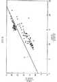
図8は、ステップS12において測定極22および対極23の間への電圧印加を再開した後におけるI/ΔIの値と、試薬層30に導入された血液の量との関係の例を表す。図8において、横軸はI(27.5)/ΔI(27.5)、縦軸はI(29.5)/ΔI(29.5)を表す。○印は、試薬層30に導入された血液の量が充分な場合、×印は血液量が不充分な場合を表す。図8から明らかなように、直線Eを境界線として、直線Eよりも上側では試薬層30に導入された血液の量は充分であり、直線Eよりも下側では血液量は不充分である。横軸をI(25.5)/ΔI(25.5)、縦軸をI(27.5)/ΔI(27.5)とした場合も、図8と同様な結果が得られる。したがって、上述のステップS13およびステップS14では、実験に基づいて適切に設定された定数e,fおよび定数g,hを使用することにより、式(3)および式(4)によって、試薬層30に導入された血液の量が不足しているか否かを適確に判定できる。
【0059】
本発明に係る定量分析方法および当該方法を実現するための定量分析装置によると、測定極22および対極23の間を流れる電流に基づいて導出されたパラメータを用いて血液量が不足しているか否かが判定される。そのため、その判定結果を利用することにより、センサ21の試薬層30に導入された試料液としての血液の不足に起因する誤測定を有効に低減することができる。血液量が不足しているか否かの判定に際して、温度センサ9により検出された温度が考慮されているので、定量分析装置の雰囲気温度の変化による誤判定を防止できる。
【0060】
試薬層30への血液導入が検出された時刻t0の後、時刻t1までの例えば1秒間、試薬層30への所定電圧の印加を継続し、この間に測定された電流に基づいて導出されたパラメータを用いて血液の不足が判定される。そのため、試薬層30に導入された血液が不足しているか否かを早期に精度良く判定できる。
【0061】
血液導入の後に試薬層30における反応を促進するために所定期間にわたって試薬層30への電圧印加を停止し、その後に測定極22および対極23の間に電圧を印加してグルコースの濃度が測定される。そのため、早期に血液の不足を検出して無駄な測定をなくすためには、電圧印加停止期間が始まる前に血液の不足を正確に判定できるのが好ましい。しかしながら、時刻t0の直後までにおいては、測定極22および対極23の間を流れる電流は微量であって不安定であるため、従来の定量分析装置のように時刻t0で電圧印加停止期間を開始したのでは、血液量の不足を正確に判定することは困難である。より具体的には、従来、時刻t0においては、試薬層30に血液が導入されたか否かのみを判定すればよいと考えられており、全分析時間の短時間化に資するべく、判定の閾値が充分に低く設定される傾向にあった。したがって、時刻t0において測定極22および対極23の間を流れる電流は極めて小さくしかも不安定であるため、判定閾値に達する以前における電流値のみを用いて血液量の不足を判定した場合、必ずしも正確な判定結果を得ることは困難であった。
【0062】
これに対し本実施形態においては、測定極22および対極23への電圧印加を、時刻t0から有意な時間が経過した時刻t1まで継続し、その間に測定極22および対極23の間を流れる電流に基づいて導出されたパラメータを用いて血液の不足を判定することにより、誤判定の防止が図られている。
【0063】
本実施形態では、ステップS6およびステップS7の2回の判定、およびステップS13およびステップS14の2回の判定が用意されている。それぞれにおいて2回の判定がともに血液不足を示す場合にのみ、試薬層30に導入された血液の量が不足していると最終決定される。そのため、測定極22および対極23の間を流れる電流の不安定さに起因する、血液不足でないにも係わらず血液不足であると判定する誤判定を良好に防止できる。
【0064】
本実施形態では、測定極22および対極23への電圧印加停止期間の前後において血液不足か否かの判定を行う。したがって、電圧印加停止期間の前における判定により、無駄な測定時間の浪費を良好に防止できる。加えて、電圧印加停止期間の後における判定により、血液不足であるにも係わらず血液不足でないと最終的に判定する誤判定を良好に防止できる。
【0065】
上述の定量分析装置を用いて次のような条件で実験を行った。
【0066】
試料液として、血液の代わりに、濃度の異なる3つのグルコース水溶液を用いた。低濃度のグルコース水溶液は、グルコース54mg/dL、安息香酸1g/L、アシッドレッド0.1g/Lを含む。中濃度のグルコース水溶液は、グルコース86mg/dL、安息香酸1g/L、アシッドレッド0.1g/Lを含む。高濃度のグルコース水溶液は、グルコース286mg/dL、安息香酸1g/L、アシッドレッド0.1g/Lを含む。測定極22および対極23の間に印加する電圧の励起パターン、および測定電流に基づいて導出したパラメータ、ならびにそれらのパラメータを用いた判定のための演算式は上記実施形態の通りである。実験に用いたセンサ21の個数は、低濃度、中濃度、高濃度のグルコース水溶液についてそれぞれ50個である。それぞれにおいて、50個のうち25個には不充分な量のグルコース水溶液を供給し、残りの25個には充分な量のグルコース水溶液を供給した。ここで、不充分な量とは1.2〜1.5μLであり、充分な量とは2μLである。
【0067】
図9は、このような条件下での実験結果を表す。グルコース濃度の高低に係わらず、不充分量供給時に血液量は不充分であると最終決定される確率は100パーセントであり、充分量供給時に血液量は不充分であると最終決定される確率は0パーセントであった。グルコース濃度の高低に係わらず、誤判定は発生しなかった。
【0068】
本発明においては、試薬層30に導入された血液の量が不足しているか否かを判定するためのパラメータとしては、測定極22および対極23の間を流れる電流の電流値Iや、所定時間における電流の差分ΔIに代えて、電流の微分値dI/dtを用いてもよい。上述の実施形態においては、互いに測定時刻の異なる2つの測定電流に基づいて血液量が不足しているか否かを判定したが、所定時点における1つの測定電流に基づいて判定してもよい。上述の実施形態では、連続的に行われる2回の判定がいずれも血液量不足を示す場合にのみ、血液量は不足していると最終決定したが、1回の判定が血液量不足を示す場合に、血液量は不足していると最終決定してもよい。或は、連続的に行われる3回以上の判定がいずれも血液量不足を示す場合にのみ、血液量は不足していると最終決定してもよい。上述の実施形態では、測定極22および対極23の間に対する電圧印加を停止している期間の前および後において、それぞれ血液量が不足しているか否かを判定したが、いずれか一方のみでもよい。上述の実施形態では、電圧印加停止期間の前の時刻t0の前および後において、それぞれ血液量が不足しているか否かを判定したが、いずれか一方のみでもよい。上述の実施形態では、第2タイマの作動中、測定極22および対極23の間への電圧印加を停止したが、電極間に実質的に電流が流れない程度の低電圧を印加し続けてもよい。上述の実施形態では、ポテンシャルステップ法を採用したが、本発明はポテンシャルステップ法に限定されるものではない。上述の実施形態では、試料液は血液であって被検成分はグルコースである場合について説明したが、本発明はこれらに限定されない。上述の実施形態では、試料液の不足を検出する例について説明したが、試料液の供給量が充分であるにも係わらず不足が検出される場合は、試料液のヘマトクリットや粘性が高いと判断できるので、本発明によると、ヘマトクリットや粘性などの試料液の状態を検出することもできる。
【図面の簡単な説明】
【図1】 図1は、センサを用いた本発明に係る定量分析装置の概略回路ブロック図である。
【図2】 図2は、センサの斜視図である。
【図3】 図3は、図2に示すセンサの分解斜視図である。
【図4】 図4は、図1に示す定量分析装置による分析動作のフローチャートである。
【図5】 図5は、測定極および対極の間に印加される電圧の時間変化、および、測定極および対極の間を流れる電流の時間変化を表す。
【図6】 図6は、測定極および対極の間への電圧印加を停止する前における、測定極および対極の間を流れる電流の時間的変化を表す。
【図7】 図7は、測定極および対極の間への電圧印加を再開した後における、I/ΔIの値の時間的変化を表す。
【図8】 図8は、測定極および対極の間への電圧印加を再開した後におけるI/ΔIの値と、試薬層に導入された血液の量との関係を表す。
【図9】 図9は、図1に示す定量分析装置を用いた実験結果を表す。
【図10】 図10は、従来の定量分析装置における、印加電圧の時間変化、および、測定電流の時間変化を表す。[0001]
【Technical field】
The present invention relates to a quantitative analysis method and a quantitative analysis apparatus for electrochemically measuring the concentration of a test component contained in a sample solution using a sensor.
[0002]
[Background]
As one of means for quantifying a test component contained in a sample solution, a method of electrochemically measuring the concentration of the test component in the sample solution using a sensor is known. As the sensor, a capillary type sensor configured so that a sample solution is supplied to the reagent layer by utilizing a capillary phenomenon is widely used. In general, a capillary sensor has a capillary having a suction port, and a pair of electrodes and a reagent layer laminated thereon are provided in the capillary. The reagent layer contains various reagents necessary for a predetermined reaction system, such as a redox chemical substance or redox enzyme corresponding to a test component, that is, a quantification target.
[0003]
When a test component contained in a reagent solution is quantified using such a sensor, for example, the sensor is set in a quantitative analyzer, and a sample solution is supplied to a suction port of a capillary in the sensor. At this time, the pair of electrodes of the sensor is electrically connected to voltage application means incorporated in the quantitative analysis device. The sample solution moves in the capillary by capillary action to reach the reagent layer, and dissolves a reagent such as a redox agent contained in the reagent layer. Some of these reagents react specifically with the test components in the sample solution. Thereafter, when a predetermined voltage is applied from the quantitative analyzer to the reagent layer, a current corresponding to the concentration of the test component flows between the pair of electrodes. This current is measured by a quantitative analyzer. Based on the measured current and a calibration curve or calibration formula prepared in advance, the concentration of the test component is determined.
[0004]
For example, when measuring the glucose concentration in blood, a biosensor having a reagent layer containing glucose oxidase and potassium ferricyanide is used. When blood is introduced into this reagent layer, glucose oxidase acquires electrons by oxidizing glucose, and potassium ferricyanide is reduced to potassium ferrocyanide by receiving the electrons from glucose oxidase. Thus, potassium ferrocyanide corresponding to the glucose concentration in the blood is produced. When a predetermined voltage is applied between the pair of electrodes, a current corresponding to the potassium ferrocyanide concentration flows between the electrodes. Since the potassium ferrocyanide concentration corresponds to the glucose concentration in the blood, the glucose concentration in the blood can be known by measuring this current.
[0005]
As a conventional quantitative analysis apparatus for electrochemically measuring the concentration of a test component in a sample solution using a sensor, an automatic quantitative analysis apparatus using a disposable step sensor and employing a potential step method is known. ing. Such an automatic quantitative analysis apparatus is generally configured to automatically start a measurement operation when a sample solution is introduced into a reagent layer. Specifically, when the sensor is set in the quantitative analyzer, a predetermined voltage is applied between the pair of electrodes of the sensor as shown in FIG. When the sample solution is supplied to the capillary inlet of the sensor, the sample solution is introduced into the reagent layer by capillary action, and the current flowing between the electrodes changes. Due to this change in current, the automatic quantitative analyzer detects that the sample solution has been introduced into the reagent layer, and stops the voltage application between the electrodes (time t0). After the predetermined time has elapsed, the automatic quantitative analyzer resumes the voltage application between the electrodes (time t2) And measure the current flowing between the electrodes. Next, the automatic quantitative analysis apparatus determines the concentration of the test component based on the result of this measurement and a table created from, for example, a calibration curve or a calibration formula.
[0006]
However, such a conventional automatic quantitative analyzer determines only whether or not the sample liquid is introduced into the reagent layer based on the current flowing between the pair of electrodes, and the amount of the sample liquid introduced into the reagent layer. Start the measurement without considering Therefore, according to the conventional automatic quantitative analyzer, the concentration of the test component may be erroneously derived due to the lack of the sample solution.
[0007]
For example, when the sample liquid is blood, even if the amount of blood supplied to the sensor is appropriate, the amount of blood introduced into the reagent layer due to capillary action is insufficient due to high hematocrit and viscosity. Sometimes. When the amount of blood supplied to the sensor is insufficient, the amount of blood reaching the reagent layer is insufficient even if the hematocrit or viscosity is not high. In these cases, according to the above-described conventional automatic quantitative analysis apparatus, a measurement result including an unacceptable error is derived in the measurement of the glucose concentration in blood.
[0008]
Japanese Patent Publication No. 8-502589 discloses a method and apparatus for setting two thresholds for the current flowing through the reaction region in the test cell and recognizing whether the amount of the sample liquid supplied to the test cell is sufficient. Is disclosed. In this prior art, the first threshold value is set in advance to detect that the sample liquid has been introduced into the reaction region, and the larger second threshold value is sufficient for this amount to continue the measurement. It is preset in order to detect whether the amount is a proper amount.
[0009]
This Japanese translation of PCT publication No. 8-502589 further discloses a method and apparatus for determining whether or not the measured current value conforms to the Cottrell equation for the current flowing through the reaction region depending on the concentration of the test component. In this prior art, a ratio between the sum of current values at a plurality of times from the start of measurement and one current value among them is obtained.
[0010]
Similarly, Japanese translation of PCT publication No. 5-502727 discloses a method for determining whether or not the measured current value conforms to the Cottrell equation for the current flowing through the reaction region depending on the concentration of the test component. In this conventional technique, a ratio of current values at two different times from the start of measurement is obtained.
[0011]
The present invention has been conceived under such circumstances, and even when the current depending on the concentration of the test component does not follow the Cottrel equation, based on the measured current, It is an object of the present invention to provide a quantitative analysis method and a quantitative analysis apparatus capable of appropriately detecting the state of a sample liquid introduced into a reagent layer in a sensor, particularly a shortage thereof.
[0012]
DISCLOSURE OF THE INVENTION
According to the first aspect of the present invention, a reagent layer containing a reagent that reacts with a test component in a sample solutionAndA sensor comprising a first electrode and a second electrode for applying a voltage to the reagent layerSet in the quantitative analysis device, apply a voltage between the first electrode and the second electrode only for the first period after the sensor is set, then stop the voltage application for the second period, and then the third period In the sample solution introduced into the reagent layer in the first period by applying a voltage again between the first electrode and the second electrodeA quantitative analysis method for electrochemically measuring the concentration of a test component is provided. This methodIn the first period,Of the first electrode and the second electrodeBetweenMeasure the flowing currentFirstCurrent measurement processIn the first current measurement processBased on the measured currentFirstDeriving parametersFirstA parameter derivation process;The first parameter obtained in the first parameter derivation stepParameter and at least one predeterminedFirstSample solution introduced into the reagent layer based on the constantsA first determination step for determining whether or not the sample liquid is insufficient, and a measurement end step for notifying the fact and ending the measurement when it is determined that the sample liquid is insufficient in the first determination step; In the third period, the second current measurement step for measuring the current flowing between the first electrode and the second electrode, and the first parameter different from the first parameter based on the current measured in the second current measurement step A second parameter derivation step for deriving two parameters, a second parameter obtained in the second parameter derivation step, and a second constant different from at least one predetermined first constant , A second determination step for determining whether or not the sample liquid introduced into the reagent layer is insufficient, and a notification for notifying that if the second determination step determines that the sample liquid is insufficient Process andincluding.
[0013]
[0014]
Preferably,FirstThe parameter is the current flowing between the first electrode and the second electrodeAt the time when it was detected that the sample solution was introduced into the reagent layer.Current value andAt the time before or after the predetermined timeThe difference with the current value at the time is included. Preferably,The determination process for determining whether or not the sample solution introduced into the reagent layer in the first period is insufficient includes a first series of steps and a second series each including a first current measurement step to a first determination step. In the first series of steps, the current value at the time when it was detected that the sample liquid was introduced into the reagent layer of the current flowing between the first electrode and the second electrode and a predetermined time before The first difference from the current value at the time is derived as a first parameter, and it is determined whether the sample liquid is insufficient based on the first difference and the first first constant, and the second In the series of steps, the current value at the time when it is detected that the sample liquid is introduced into the reagent layer of the current flowing between the first electrode and the second electrode and the current value at the time after the predetermined time are calculated. The difference of 2 is derived as the first parameter and the second Difference and the second1If it is determined whether the sample liquid is insufficient based on the second first constant different from the first constant, and it is determined that the sample liquid is insufficient in the first series of steps, When the second series of steps is performed and the measurement end process determines that the sample liquid is insufficient in the second series of processes, it indicates that the sample liquid introduced into the reagent layer is insufficient. Informs and ends the measurement.Preferably,SecondThe parameter is a second predetermined value from the first predetermined time point according to the first difference between the current value at the first predetermined time point and the current value at the second predetermined time point of the current flowing between the first electrode and the second electrode. The first value obtained by dividing the current value at the third predetermined time point included in the period between the time points, and the second difference between the current value at the fourth predetermined time point and the current value at the fifth predetermined time point, And a third difference from the second value obtained by dividing the current value at the sixth predetermined time point included in the period between the four predetermined time points and the fifth predetermined time point.
[0015]
Preferably,SecondCurrent measurement processTo the secondJudgment processFor up toThe series of processes isWhen it is determined by the second determination step that the sample liquid is insufficient, the determination is performed again based on a predetermined time point and a second constant different from the previous time, and when a series of steps are performed a predetermined number of times, By the second judgment processIf it is determined that the sample liquid is insufficient,The notification processThe sample solution introduced into the reagent layer is insufficient.Inform the effect.
[0016]
According to the second aspect of the present invention, a reagent layer containing a reagent that reacts with a test component in a sample solution and a voltage for applying a voltage to the reagent layer.1A sensor including an electrode and a second electrode is set in a quantitative analyzer, and a voltage is applied to the first electrode and the second electrode of the sensor to electrically measure the concentration of the test component in the sample solution introduced into the reagent layer. A quantitative analysis method for chemically measuring, a first determination step for determining whether or not a sample solution is insufficient in a predetermined period before and after the detection of the introduction of the sample solution into the reagent layer If the first determination step determines that the sample solution is insufficient, the second determination step determines again whether the sample solution is insufficient, and the second determination step causes the sample solution to be insufficient. If it is determined that the measurement is being performed, a measurement end step of notifying the fact and ending the measurement is included.
[0017]
According to the third aspect of the present invention, there is provided a reagent layer containing a reagent that reacts with a test component in a sample solution and a voltage for applying a voltage to the reagent layer.1A sensor including an electrode and a second electrode is set in a quantitative analyzer, and a voltage is applied to the first electrode and the second electrode of the sensor to electrically measure the concentration of the test component in the sample solution introduced into the reagent layer. A quantitative analysis method for chemical measurement, in which the application of voltage is stopped after a predetermined time after it is detected that the sample liquid has been introduced into the reagent layer, and the voltage is applied again after a predetermined time from the stop. In a predetermined period, a first determination step for determining whether or not the sample solution is insufficient, and if it is determined that the sample solution is insufficient in the first determination step, whether or not the sample solution is insufficient is determined. It includes a second determination step for determining again, and a notification step for notifying that if the second determination step determines that the sample liquid is insufficient.
[0018]
[0019]
[0020]
According to the fourth aspect of the present invention, a reagent layer containing a reagent that reacts with a test component in a sample solutionAndA sensor comprising a first electrode and a second electrode for applying a voltage to the reagent layerThe voltage is applied between the first electrode and the second electrode only for the first period after the sensor is set, and then the voltage application is stopped only for the second period, and then the first electrode is applied in the subsequent third period. In the sample liquid introduced into the reagent layer in the first period by applying a voltage again between the second electrode and the second electrode.Provided is a quantitative analysis apparatus for electrochemically measuring the concentration of a test component. This device applies a voltage between the first electrode and the second electrode.RudenPressure applying means;In the first period,Measure the current flowing between the first and second electrodesFirstCurrent measuring means;FirstBased on the measurement results obtained by the current measuring meansFirstDeriving parametersFirstComputing means;FirstDerived by computing meansFirstParameter and at least one predeterminedFirstBased on the constant andIntroduced into the reagent layerDetermine whether the sample solution is insufficientFirstJudgment meansIf the first determination means determines that the sample liquid is insufficient, a measurement end means for informing the fact and ending the measurement, and between the first electrode and the second electrode in the third period. A second current measuring means for measuring a flowing current; a second computing means for deriving a second parameter different from the first parameter based on a measurement result obtained by the second current measuring means; Whether or not the sample liquid introduced into the reagent layer is insufficient is determined based on the second parameter derived by the computing means and a second constant that is different from at least one predetermined first constant. A second determination unit that performs notification, and a notification unit that notifies the fact when the second determination unit determines that the sample liquid is insufficient.Is provided.
[0021]
Preferably,The first parameter is a current value at the time when it is detected that the sample liquid is introduced into the reagent layer of the current flowing between the first electrode and the second electrode, and a time point before or a predetermined time.Includes the difference from the current value at a later time. Preferably,The introduced current value at the time when the first arithmetic means detects that the sample liquid is introduced into the reagent layer of the current flowing between the first electrode and the second electrode, and the current value at the time before the predetermined time. When the first difference is derived as the first parameter and the first determination unit determines that the sample liquid is insufficient based on the first difference and the first first constant, The calculation means derives a second difference between the introduction current value and the current value at a time point after the predetermined time as a first parameter, and the first determination means determines the second difference and the second difference.1When it is determined that the sample liquid is insufficient based on the second first constant different from the first constant, the measurement ending means notifies that the sample liquid introduced into the reagent layer is insufficient. To finish the measurement. Preferably,SecondThe calculation means isSecondAs at least a part of the parameter, from the first predetermined time point, the first difference between the current value at the first predetermined time point and the current value at the second predetermined time point of the current flowing between the first electrode and the second electrode. A second value of the first value obtained by dividing the current value at the third predetermined time point included in the period between the second predetermined time points, the current value at the fourth predetermined time point, and the current value at the fifth predetermined time point. A third difference from the second value obtained by dividing the first flow value is derived from the difference.
[0022]
Preferably,If the second determining means determines that the sample liquid is insufficient based on the second parameter derived by the second calculating means and the second constant, the second calculating means Derives again the second parameter at a different predetermined time point, the second determination means makes a determination again based on the second parameter and a second constant different from the previous time, and the second computing means When the second determination means determines that the sample liquid is insufficient when the derivation of the
[0023]
[0024]
[0025]
[0026]
According to a fifth aspect of the present invention,A reagent layer containing a reagent that reacts with a test component in a sample solution and a voltage for applying a voltage to the reagent layer1A sensor comprising an electrode and a second electrode is set, and the concentration of the test component in the sample solution introduced into the reagent layer by applying a voltage between the first electrode and the second electrode of the sensor is measured electrochemically. For quantitative analysisIs provided. thisapparatusIsVoltage application means for applying a voltage between the first electrode and the second electrode, and whether or not the sample liquid is insufficient in a predetermined period before and after the detection of the introduction of the sample liquid into the reagent layer A first determination unit for determining, a second determination unit for determining again whether or not the sample solution is insufficient, and a second determination unit when the first determination unit determines that the sample solution is insufficient; If the determination means determines that the sample liquid is insufficient, a measurement end means is provided for informing that and terminating the measurement..
[0027]
According to the sixth aspect of the present invention, there is provided a reagent layer containing a reagent that reacts with a test component in a sample solution and a voltage for applying a voltage to the reagent layer.1A sensor comprising an electrode and a second electrode is set, and the concentration of the test component in the sample solution introduced into the reagent layer by applying a voltage between the first electrode and the second electrode of the sensor is measured electrochemically. An apparatus for quantitative analysis is provided. This device stops applying the voltage after a predetermined time after it is detected that the sample liquid is introduced into the reagent layer, and the sample liquid is insufficient for a predetermined period when the voltage is applied again after the predetermined time from the stop. First determination means for determining whether or not the sample liquid is insufficient by the first determination means, and second determination means for determining again whether or not the sample liquid is insufficient. And a notifying means for notifying that when the second determining means determines that the sample liquid is insufficient.
[0028]
BEST MODE FOR CARRYING OUT THE INVENTION
Hereinafter, preferred embodiments of the present invention will be described in detail with reference to the drawings.
[0029]
FIG. 1 is a schematic circuit block diagram of a quantitative analysis apparatus according to the present invention using a sensor. In the present embodiment, it is assumed that the glucose concentration in blood is measured by this quantitative analyzer. Therefore, the
[0030]
The
[0031]
FIG. 2 is a perspective view of the
[0032]
A
[0033]
The
[0034]
FIG. 4 is a flowchart of the analysis operation by the quantitative analysis apparatus shown in FIG. FIG. 5 shows the time change of the voltage applied between the
[0035]
In step S1, the
[0036]
When the
[0037]
Next, in step S3, the
[0038]
Next, in step S <b> 4, the
[0039]
When blood is introduced into the reagent layer 30 (S4: YES), the
[0040]
Next, in step S6, the
[0041]
[Expression 1]
If it is determined in step S6 that the blood volume is insufficient (S6: YES), in step S7, the
[0043]
[Expression 2]
When it is determined in step S7 that the blood volume is not insufficient (S7: NO), in step S8, the
[0045]
When it is determined in step S6 that the blood volume is not insufficient (S6: NO), step S7 is performed without performing step S7. If it is determined in step S7 that the blood volume is insufficient (S7: YES), in step S18, the
[0046]
After the voltage application is stopped in step S9, in step S10, the
[0047]
Next, in step S11, the
[0048]
Next, in
[0049]
[Equation 3]
If it is determined in step S13 that the blood volume is insufficient (S13: YES), in step S14, the
[0051]
[Expression 4]
When it is determined in step S14 that the blood volume is not insufficient (S14: NO), in step S15, the
[0053]
When it is determined in step S13 that the blood volume is not insufficient (S13: NO), step S14 is performed without performing step S14. If it is determined in step S14 that the blood volume is insufficient (S14: YES), in step S17, the
[0054]
Next, in step S <b> 16, the
[0055]
FIG. 6 illustrates an example of a temporal change in the current flowing between the
[0056]
FIG. 7 shows an example of a temporal change in the value of I / ΔI after resuming the voltage application between the
[0057]
[Equation 5]
FIG. 8 shows an example of the relationship between the value of I / ΔI and the amount of blood introduced into the
[0059]
According to the quantitative analysis method and the quantitative analysis apparatus for realizing the method according to the present invention, whether or not the blood volume is insufficient using the parameters derived based on the current flowing between the
[0060]
Time t when blood introduction into the
[0061]
In order to promote the reaction in the
[0062]
In contrast, in this embodiment, voltage application to the
[0063]
In the present embodiment, two determinations of step S6 and step S7 and two determinations of step S13 and step S14 are prepared. Only when each of the two determinations indicates a lack of blood, it is finally determined that the amount of blood introduced into the
[0064]
In the present embodiment, it is determined whether or not there is a blood shortage before and after the voltage application stop period to the
[0065]
The experiment was conducted under the following conditions using the above quantitative analyzer.
[0066]
As the sample solution, three glucose aqueous solutions having different concentrations were used instead of blood. The low-concentration glucose aqueous solution contains 54 mg / dL of glucose, 1 g / L of benzoic acid, and 0.1 g / L of acid red. The medium concentration glucose aqueous solution contains 86 mg / dL of glucose, 1 g / L of benzoic acid, and 0.1 g / L of acid red. The high-concentration glucose aqueous solution contains glucose 286 mg / dL, benzoic acid 1 g / L, and acid red 0.1 g / L. The excitation pattern of the voltage applied between the
[0067]
FIG. 9 shows the experimental results under such conditions. Regardless of whether the glucose concentration is high or low, the probability that the blood volume is finally determined to be insufficient when supplying an insufficient amount is 100 percent, and the probability that the blood volume is determined to be insufficient when supplying a sufficient amount is 0 percent. No misjudgment occurred regardless of the glucose level.
[0068]
In the present invention, as a parameter for determining whether or not the amount of blood introduced into the
[Brief description of the drawings]
FIG. 1 is a schematic circuit block diagram of a quantitative analysis apparatus according to the present invention using a sensor.
FIG. 2 is a perspective view of a sensor.
FIG. 3 is an exploded perspective view of the sensor shown in FIG. 2;
FIG. 4 is a flowchart of an analysis operation performed by the quantitative analysis apparatus shown in FIG.
FIG. 5 shows a time change of a voltage applied between a measurement electrode and a counter electrode and a time change of a current flowing between the measurement electrode and the counter electrode.
FIG. 6 shows a temporal change in the current flowing between the measurement electrode and the counter electrode before the voltage application between the measurement electrode and the counter electrode is stopped.
FIG. 7 shows a temporal change in the value of I / ΔI after resuming the application of voltage between the measurement electrode and the counter electrode.
FIG. 8 shows the relationship between the value of I / ΔI and the amount of blood introduced into the reagent layer after resumption of voltage application between the measurement electrode and the counter electrode.
FIG. 9 shows the results of an experiment using the quantitative analysis apparatus shown in FIG.
FIG. 10 shows a time change of applied voltage and a time change of measurement current in a conventional quantitative analyzer.
Claims (14)
Translated fromJapanese前記第1期間において、前記第1電極および第2電極の間を流れる電流を測定する第1の電流測定工程と、
前記第1の電流測定工程において測定された前記電流に基いて第1のパラメータを導出する第1のパラメータ導出工程と、
前記第1のパラメータ導出工程において得られた前記第1のパラメータと予め決定されている少なくとも1つの第1定数とに基づいて、前記試薬層に導入された前記試料液が不足しているかどうかを判定する第1の判定工程と、
前記第1の判定工程により前記試料液が不足していると判定されると、その旨を報知して測定を終了する測定終了工程と、
前記第3期間において、前記第1電極および第2電極の間を流れる電流を測定する第2の電流測定工程と、
前記第2の電流測定工程において測定された前記電流に基いて前記第1のパラメータとは異なる第2のパラメータを導出する第2のパラメータ導出工程と、
前記第2のパラメータ導出工程において得られた前記第2のパラメータと予め決定されている少なくとも1つの前記第1定数とは異なる第2定数とに基づいて、前記試薬層に導入された前記試料液が不足しているかどうかを判定する第2の判定工程と、
前記第2の判定工程により前記試料液が不足していると判定されると、その旨を報知する報知工程と、
を含む、定量分析方法。A sensor and a first electrode and a second electrode for applying a voltage to the reagent layerand those reagent layer containing a reagent which reacts with a test component in the sample liquidwas set in quantitative analysis apparatus, the sensor is set After that, a voltage is applied between the first electrode and the second electrode only for the first period, and then the voltage application is stopped only for the second period, and then the first electrode and the second electrode are stopped in the third period thereafter. A quantitative analysis method for electrochemically measuring the concentration of the test componentin the sample solution introduced into the reagent layer in the first period by applying a voltage again in the middle ,
Inthe first period, afirst current measuring stepyou measure the current flowingbetween the first electrode and the secondelectrode,
Afirst parameter derivation stepyou derive afirst parameter based on the current measured in theprevious SL first current measuring step,
Based on at least one of the first constant is predetermined and thefirst parameters obtained in the first parameter derivation step, whether the sample liquid introduced to the reagent layer is insufficient afirst determination stepyou determination,
When it is determined by the first determination step that the sample liquid is insufficient, a measurement end step for notifying the fact and ending the measurement,
Inthe third period, asecond current measuring stepyou measure the current flowing between the previousSL first electrode and the second electrode,
Asecond parameter derivation stepyou derive thedifferent second parametersfrom said based on said measured currentfirst parameter in the second current measuring step,
The sample solution introduced into the reagent layer based onthe second parameter obtained in the second parameter derivation step and a second constantdifferent from at least one ofthe first constants determined in advance. asecond determination step butyou determine if missing,
When it is determined by the second determination step that the sample liquid is insufficient, a notification step for notifying that effect;
Including quantitative analysis.
前記第1の一連の工程では、前記第1電極および前記第2電極の間を流れる電流の前記試薬層に前記試料液が導入されたことが検出された時点の電流値とその所定時間前の時点における電流値との第1の差分が前記第1のパラメータとして導出され、当該第1の差分と第1の前記第1定数とに基づいて前記試料液が不足しているかどうかが判定され、
前記第2の一連の工程では、前記第1電極および前記第2電極の間を流れる電流の前記試薬層に前記試料液が導入されたことが検出された時点の電流値とその所定時間後の時点における電流値との第2の差分が前記第1のパラメータとして導出され、当該第2の差分と前記第1の第1定数とは異なる第2の前記第1定数とに基づいて前記試料液が不足しているかどうかが判定され、
前記第1の一連の工程において前記試料液は不足していると判定された場合は、前記第2の一連の工程が行なわれ、
前記測定終了工程は、第2の一連の工程において前記試料液は不足していると判定されると、前記試薬層に導入された前記試料液は不足している旨を報知して測定を終了する、請求項1に記載の定量分析方法。A determination process for determining whether or not the sample liquid introduced into the reagent layer in the first period is insufficient includes a first series of steps each including the first current measurement step to the first determination step. And a second series of steps,
In the first series of steps, a current value at the time when it is detected that the sample liquid is introduced into the reagent layer of a current flowing between the first electrode and the second electrode, and a predetermined time before A first difference with a current value at a time point is derived as the first parameter, and it is determined whether the sample liquid is insufficient based on the first difference and the first constant.
In the second series of steps, a current value at the time when it is detected that the sample liquid is introduced into the reagent layer of a current flowing between the first electrode and the second electrode and a predetermined time later second difference between the current value at the time is derived as the first parameter,the sample solution on the basis of a different second of the first constantandthe second differencebetweenthefirstfirst constant Is determined whether or not
When it is determined that the sample liquid is insufficient in the first series of steps, the second series of steps is performed,
When it is determined that the sample solution is insufficient in the second series of steps, the measurement end step informs that the sample solution introduced into the reagent layer is insufficient and ends the measurement. to quantitative analysis method according to claim1.
前記試薬層に前記試料液が導入されたことが検出された時点の前後の所定期間において、前記試料液が不足しているかどうかを判定する第1の判定工程と、 A first determination step of determining whether or not the sample liquid is insufficient in a predetermined period before and after the time when it is detected that the sample liquid is introduced into the reagent layer;
前記第1の判定工程により前記試料液が不足していると判定されると、前記試料液が不足しているかどうかを再度判定する第2の判定工程と、 When it is determined by the first determination step that the sample solution is insufficient, a second determination step of determining again whether the sample solution is insufficient,
前記第2の判定工程により前記試料液が不足していると判定されると、その旨を報知して測定を終了する測定終了工程と、 When it is determined by the second determination step that the sample liquid is insufficient, a measurement end step for notifying the fact and ending the measurement,
を含む、定量分析方法。Including quantitative analysis.
前記試薬層に前記試料液が導入されたことが検出されてからの所定時間後に前記電圧の印加を停止し、停止から所定時間後に再度前記電圧を印加している所定期間において、前記試料液が不足しているかどうかを判定する第1の判定工程と、 In a predetermined period in which the application of the voltage is stopped after a predetermined time after it is detected that the sample liquid is introduced into the reagent layer, and the voltage is applied again after a predetermined time from the stop. A first determination step of determining whether or not it is insufficient;
前記第1の判定工程により前記試料液が不足していると判定されると、前記試料液が不足しているかどうかを再度判定する第2の判定工程と、 When it is determined by the first determination step that the sample solution is insufficient, a second determination step of determining again whether the sample solution is insufficient,
前記第2の判定工程により前記試料液が不足していると判定されると、その旨を報知する報知工程と、 When it is determined by the second determination step that the sample liquid is insufficient, a notification step for notifying that effect;
を含む、定量分析方法。Including quantitative analysis.
前記第1電極および前記第2電極の間に電圧を印加する電圧印加手段と、 Voltage applying means for applying a voltage between the first electrode and the second electrode;
前記第1期間において、前記第1電極および第2電極の間を流れる電流を測定する第1の電流測定手段と、 First current measuring means for measuring a current flowing between the first electrode and the second electrode in the first period;
前記第1の電流測定手段により得られる測定結果に基づいて第1のパラメータを導出する第1の演算手段と、 First computing means for deriving a first parameter based on a measurement result obtained by the first current measuring means;
前記第1の演算手段により導出された前記第1のパラメータと予め決定されている少なくとも1つの第1定数とに基づいて、前記試薬層に導入された前記試料液が不足しているかどうかを判定する第1の判定手段と、 Whether the sample liquid introduced into the reagent layer is insufficient is determined based on the first parameter derived by the first calculation means and at least one first constant determined in advance. First determining means for
前記第1の判定手段により前記試料液が不足していると判定されると、その旨を報知して測定を終了する測定終了手段と、 When it is determined by the first determination means that the sample liquid is insufficient, a measurement end means for informing that and ending the measurement;
前記第3期間において、前記第1電極および第2電極の間を流れる電流を測定する第2の電流測定手段と、 A second current measuring means for measuring a current flowing between the first electrode and the second electrode in the third period;
前記第2の電流測定手段により得られる測定結果に基いて前記第1のパラメータとは異なる第2のパラメータを導出する第2の演算手段と、 Second computing means for deriving a second parameter different from the first parameter based on a measurement result obtained by the second current measuring means;
前記第2の演算手段により導出された前記第2のパラメータと予め決定されている少なくとも1つの前記第1定数とは異なる第2定数とに基づいて、前記試薬層に導入された前記試料液が不足しているかどうかを判定する第2の判定手段と、 Based on the second parameter derived by the second calculating means and a second constant different from at least one of the first constants determined in advance, the sample liquid introduced into the reagent layer is A second determination means for determining whether there is a shortage;
前記第2の判定手段により前記試料液が不足していると判定されると、その旨を報知する報知手段と、 When it is determined by the second determination means that the sample liquid is insufficient, a notification means for notifying that effect;
を備える、定量分析装置。A quantitative analysis apparatus comprising:
前記第1電極および前記第2電極の間に電圧を印加する電圧印加手段と、
前記試薬層に前記試料液が導入されたことが検出された時点の前後の所定期間において、前記試料液が不足しているかどうかを判定する第1の判定手段と、
前記第1の判定手段により前記試料液が不足していると判定されると、前記試料液が不足しているかどうかを再度判定する第2の判定手段と、
前記第2の判定手段により前記試料液が不足していると判定されると、その旨を報知して測定を終了する測定終了手段と、
を備える、定量分析装置。A sensor and afirstelectrode and a second electrodefor applying a voltage to the reagent layer and the reagent layer containing a reagent which reacts with a test component in the sample liquidis set, the first electrode of the sensor and a second A quantitative analysis apparatus for electrochemically measuring a concentration of the test component in the sample liquid introduced into the reagent layer by applying a voltage between electrodes;
Voltage applying means for applying a voltage between the first electrode and the second electrode;
First determination means for determining whether or not the sample liquid is insufficient in a predetermined period before and after the time when it is detected that the sample liquid is introduced into the reagent layer;
When it is determined by the first determination means that the sample liquid is insufficient, second determination means for determining again whether the sample liquid is insufficient;
When it is determined by the second determination means that the sample liquid is insufficient, a measurement end means for informing that and terminating the measurement;
A quantitative analysis apparatus comprising:
前記試薬層に前記試料液が導入されたことが検出されてからの所定時間後に前記電圧の印加を停止し、停止から所定時間後に再度前記電圧を印加している所定期間において、前記試料液が不足しているかどうかを判定する第1の判定手段と、
前記第1の判定手段により前記試料液が不足していると判定されると、前記試料液が不足しているかどうかを再度判定する第2の判定手段と、
前記第2の判定手段により前記試料液が不足していると判定されると、その旨を報知する報知手段と、
を備える、定量分析装置。Asensorcomprising a reagent layer containing a reagent that reacts with a test component in a sample solutionand afirstelectrode and a second electrodefor applying a voltage to the reagent layeris set, and thefirstelectrode and the second electrode of the sensor are set. A quantitative analysis apparatus for electrochemically measuring a concentration of the test component in the sample liquid introduced into the reagent layer by applying a voltage between electrodes;
In a predetermined period in which the application of the voltage is stopped after a predetermined time after it is detected that the sample liquid is introduced into the reagent layer, and the voltage is applied again after a predetermined time from the stop. First determination means for determining whether or not it is insufficient;
When it is determined by the first determination means that the sample liquid is insufficient, second determination means for determining again whether the sample liquid is insufficient;
When the second determination means determines that the sample liquid is insufficient, an informing means for informing that effect;
A quantitative analysis apparatus comprising:
Applications Claiming Priority (3)
| Application Number | Priority Date | Filing Date | Title |
|---|---|---|---|
| JP2001008953 | 2001-01-17 | ||
| JP2001008953 | 2001-01-17 | ||
| PCT/JP2002/000204WO2002057768A1 (en) | 2001-01-17 | 2002-01-15 | Quantitative analyzing method and quantitative analyzer using sensor |
Publications (2)
| Publication Number | Publication Date |
|---|---|
| JPWO2002057768A1 JPWO2002057768A1 (en) | 2004-05-27 |
| JP3972063B2true JP3972063B2 (en) | 2007-09-05 |
Family
ID=18876504
Family Applications (1)
| Application Number | Title | Priority Date | Filing Date |
|---|---|---|---|
| JP2002557999AExpired - Fee RelatedJP3972063B2 (en) | 2001-01-17 | 2002-01-15 | Quantitative analysis method and quantitative analysis apparatus using sensor |
Country Status (5)
| Country | Link |
|---|---|
| US (1) | US7351323B2 (en) |
| EP (2) | EP1369684A4 (en) |
| JP (1) | JP3972063B2 (en) |
| CN (2) | CN102012389B (en) |
| WO (1) | WO2002057768A1 (en) |
Families Citing this family (108)
| Publication number | Priority date | Publication date | Assignee | Title |
|---|---|---|---|---|
| US6391005B1 (en) | 1998-03-30 | 2002-05-21 | Agilent Technologies, Inc. | Apparatus and method for penetration with shaft having a sensor for sensing penetration depth |
| US20050103624A1 (en) | 1999-10-04 | 2005-05-19 | Bhullar Raghbir S. | Biosensor and method of making |
| US8641644B2 (en) | 2000-11-21 | 2014-02-04 | Sanofi-Aventis Deutschland Gmbh | Blood testing apparatus having a rotatable cartridge with multiple lancing elements and testing means |
| US7344507B2 (en) | 2002-04-19 | 2008-03-18 | Pelikan Technologies, Inc. | Method and apparatus for lancet actuation |
| US9226699B2 (en) | 2002-04-19 | 2016-01-05 | Sanofi-Aventis Deutschland Gmbh | Body fluid sampling module with a continuous compression tissue interface surface |
| US7749174B2 (en) | 2001-06-12 | 2010-07-06 | Pelikan Technologies, Inc. | Method and apparatus for lancet launching device intergrated onto a blood-sampling cartridge |
| US7041068B2 (en) | 2001-06-12 | 2006-05-09 | Pelikan Technologies, Inc. | Sampling module device and method |
| US9427532B2 (en) | 2001-06-12 | 2016-08-30 | Sanofi-Aventis Deutschland Gmbh | Tissue penetration device |
| US7981056B2 (en) | 2002-04-19 | 2011-07-19 | Pelikan Technologies, Inc. | Methods and apparatus for lancet actuation |
| EP1395185B1 (en) | 2001-06-12 | 2010-10-27 | Pelikan Technologies Inc. | Electric lancet actuator |
| JP4209767B2 (en) | 2001-06-12 | 2009-01-14 | ペリカン テクノロジーズ インコーポレイテッド | Self-optimized cutting instrument with adaptive means for temporary changes in skin properties |
| US9795747B2 (en) | 2010-06-02 | 2017-10-24 | Sanofi-Aventis Deutschland Gmbh | Methods and apparatus for lancet actuation |
| US8337419B2 (en) | 2002-04-19 | 2012-12-25 | Sanofi-Aventis Deutschland Gmbh | Tissue penetration device |
| US6797150B2 (en)* | 2001-10-10 | 2004-09-28 | Lifescan, Inc. | Determination of sample volume adequacy in biosensor devices |
| US7491178B2 (en) | 2002-04-19 | 2009-02-17 | Pelikan Technologies, Inc. | Method and apparatus for penetrating tissue |
| US8372016B2 (en) | 2002-04-19 | 2013-02-12 | Sanofi-Aventis Deutschland Gmbh | Method and apparatus for body fluid sampling and analyte sensing |
| US7547287B2 (en) | 2002-04-19 | 2009-06-16 | Pelikan Technologies, Inc. | Method and apparatus for penetrating tissue |
| US7297122B2 (en) | 2002-04-19 | 2007-11-20 | Pelikan Technologies, Inc. | Method and apparatus for penetrating tissue |
| US7331931B2 (en) | 2002-04-19 | 2008-02-19 | Pelikan Technologies, Inc. | Method and apparatus for penetrating tissue |
| US7708701B2 (en) | 2002-04-19 | 2010-05-04 | Pelikan Technologies, Inc. | Method and apparatus for a multi-use body fluid sampling device |
| US8702624B2 (en) | 2006-09-29 | 2014-04-22 | Sanofi-Aventis Deutschland Gmbh | Analyte measurement device with a single shot actuator |
| US7229458B2 (en) | 2002-04-19 | 2007-06-12 | Pelikan Technologies, Inc. | Method and apparatus for penetrating tissue |
| US7909778B2 (en) | 2002-04-19 | 2011-03-22 | Pelikan Technologies, Inc. | Method and apparatus for penetrating tissue |
| US9248267B2 (en) | 2002-04-19 | 2016-02-02 | Sanofi-Aventis Deustchland Gmbh | Tissue penetration device |
| US8267870B2 (en) | 2002-04-19 | 2012-09-18 | Sanofi-Aventis Deutschland Gmbh | Method and apparatus for body fluid sampling with hybrid actuation |
| US7674232B2 (en) | 2002-04-19 | 2010-03-09 | Pelikan Technologies, Inc. | Method and apparatus for penetrating tissue |
| US9314194B2 (en) | 2002-04-19 | 2016-04-19 | Sanofi-Aventis Deutschland Gmbh | Tissue penetration device |
| US8579831B2 (en) | 2002-04-19 | 2013-11-12 | Sanofi-Aventis Deutschland Gmbh | Method and apparatus for penetrating tissue |
| US8784335B2 (en) | 2002-04-19 | 2014-07-22 | Sanofi-Aventis Deutschland Gmbh | Body fluid sampling device with a capacitive sensor |
| US7976476B2 (en) | 2002-04-19 | 2011-07-12 | Pelikan Technologies, Inc. | Device and method for variable speed lancet |
| US7892183B2 (en) | 2002-04-19 | 2011-02-22 | Pelikan Technologies, Inc. | Method and apparatus for body fluid sampling and analyte sensing |
| US9795334B2 (en) | 2002-04-19 | 2017-10-24 | Sanofi-Aventis Deutschland Gmbh | Method and apparatus for penetrating tissue |
| US8221334B2 (en) | 2002-04-19 | 2012-07-17 | Sanofi-Aventis Deutschland Gmbh | Method and apparatus for penetrating tissue |
| US7232451B2 (en) | 2002-04-19 | 2007-06-19 | Pelikan Technologies, Inc. | Method and apparatus for penetrating tissue |
| US7901362B2 (en) | 2002-04-19 | 2011-03-08 | Pelikan Technologies, Inc. | Method and apparatus for penetrating tissue |
| US8360992B2 (en) | 2002-04-19 | 2013-01-29 | Sanofi-Aventis Deutschland Gmbh | Method and apparatus for penetrating tissue |
| CN100504371C (en)* | 2002-07-25 | 2009-06-24 | 爱科来株式会社 | Sample analyzing method and sample analyzer |
| US8574895B2 (en) | 2002-12-30 | 2013-11-05 | Sanofi-Aventis Deutschland Gmbh | Method and apparatus using optical techniques to measure analyte levels |
| DE602004028463D1 (en) | 2003-05-30 | 2010-09-16 | Pelikan Technologies Inc | METHOD AND DEVICE FOR INJECTING LIQUID |
| US7850621B2 (en) | 2003-06-06 | 2010-12-14 | Pelikan Technologies, Inc. | Method and apparatus for body fluid sampling and analyte sensing |
| WO2006001797A1 (en) | 2004-06-14 | 2006-01-05 | Pelikan Technologies, Inc. | Low pain penetrating |
| US7645373B2 (en) | 2003-06-20 | 2010-01-12 | Roche Diagnostic Operations, Inc. | System and method for coding information on a biosensor test strip |
| US7597793B2 (en) | 2003-06-20 | 2009-10-06 | Roche Operations Ltd. | System and method for analyte measurement employing maximum dosing time delay |
| US7867369B2 (en)* | 2003-06-20 | 2011-01-11 | Roche Diagnostics Operations, Inc. | Biosensor with multiple electrical functionalities |
| US7604721B2 (en) | 2003-06-20 | 2009-10-20 | Roche Diagnostics Operations, Inc. | System and method for coding information on a biosensor test strip |
| US8148164B2 (en) | 2003-06-20 | 2012-04-03 | Roche Diagnostics Operations, Inc. | System and method for determining the concentration of an analyte in a sample fluid |
| US7452457B2 (en)* | 2003-06-20 | 2008-11-18 | Roche Diagnostics Operations, Inc. | System and method for analyte measurement using dose sufficiency electrodes |
| US8058077B2 (en) | 2003-06-20 | 2011-11-15 | Roche Diagnostics Operations, Inc. | Method for coding information on a biosensor test strip |
| US8071030B2 (en) | 2003-06-20 | 2011-12-06 | Roche Diagnostics Operations, Inc. | Test strip with flared sample receiving chamber |
| JP4447009B2 (en) | 2003-06-20 | 2010-04-07 | エフ ホフマン−ラ ロッシュ アクチェン ゲゼルシャフト | Test strip with slot vent opening |
| US7645421B2 (en) | 2003-06-20 | 2010-01-12 | Roche Diagnostics Operations, Inc. | System and method for coding information on a biosensor test strip |
| US8206565B2 (en) | 2003-06-20 | 2012-06-26 | Roche Diagnostics Operation, Inc. | System and method for coding information on a biosensor test strip |
| US7718439B2 (en) | 2003-06-20 | 2010-05-18 | Roche Diagnostics Operations, Inc. | System and method for coding information on a biosensor test strip |
| ES2709991T3 (en) | 2003-08-21 | 2019-04-22 | Agamatrix Inc | Method and apparatus for the analysis of electrochemical properties |
| US8282576B2 (en) | 2003-09-29 | 2012-10-09 | Sanofi-Aventis Deutschland Gmbh | Method and apparatus for an improved sample capture device |
| EP1680014A4 (en) | 2003-10-14 | 2009-01-21 | Pelikan Technologies Inc | METHOD AND DEVICE FOR A VARIABLE USER INTERFACE |
| DE602004021835D1 (en)* | 2003-10-31 | 2009-08-13 | Lifescan Scotland Ltd | METHOD FOR REDUCING INTERFERENCE IN AN ELECTROCHEMICAL SENSOR USING TWO DIFFERENT APPROPRIATE POTENTIALS |
| US8668656B2 (en) | 2003-12-31 | 2014-03-11 | Sanofi-Aventis Deutschland Gmbh | Method and apparatus for improving fluidic flow and sample capture |
| US7822454B1 (en) | 2005-01-03 | 2010-10-26 | Pelikan Technologies, Inc. | Fluid sampling device with improved analyte detecting member configuration |
| EP1713926B1 (en) | 2004-02-06 | 2012-08-01 | Bayer HealthCare, LLC | Oxidizable species as an internal reference for biosensors and method of use |
| WO2006011062A2 (en) | 2004-05-20 | 2006-02-02 | Albatros Technologies Gmbh & Co. Kg | Printable hydrogel for biosensors |
| WO2005120365A1 (en) | 2004-06-03 | 2005-12-22 | Pelikan Technologies, Inc. | Method and apparatus for a fluid sampling device |
| US9775553B2 (en) | 2004-06-03 | 2017-10-03 | Sanofi-Aventis Deutschland Gmbh | Method and apparatus for a fluid sampling device |
| US7569126B2 (en) | 2004-06-18 | 2009-08-04 | Roche Diagnostics Operations, Inc. | System and method for quality assurance of a biosensor test strip |
| US7556723B2 (en) | 2004-06-18 | 2009-07-07 | Roche Diagnostics Operations, Inc. | Electrode design for biosensor |
| US8652831B2 (en) | 2004-12-30 | 2014-02-18 | Sanofi-Aventis Deutschland Gmbh | Method and apparatus for analyte measurement test time |
| US7517439B2 (en)* | 2005-04-15 | 2009-04-14 | Agamatrix, Inc. | Error detection in analyte measurements based on measurement of system resistance |
| US7344626B2 (en)* | 2005-04-15 | 2008-03-18 | Agamatrix, Inc. | Method and apparatus for detection of abnormal traces during electrochemical analyte detection |
| US7547382B2 (en)* | 2005-04-15 | 2009-06-16 | Agamatrix, Inc. | Determination of partial fill in electrochemical strips |
| US7964089B2 (en) | 2005-04-15 | 2011-06-21 | Agamatrix, Inc. | Analyte determination method and analyte meter |
| US7645374B2 (en) | 2005-04-15 | 2010-01-12 | Agamatrix, Inc. | Method for determination of analyte concentrations and related apparatus |
| GB0514728D0 (en)* | 2005-07-19 | 2005-08-24 | Hypoguard Ltd | Biosensor and method of manufacture |
| JP5385607B2 (en) | 2005-07-20 | 2014-01-08 | バイエル・ヘルスケア・エルエルシー | Gated current measuring instrument |
| WO2007026683A1 (en) | 2005-09-02 | 2007-03-08 | Arkray, Inc. | Method for detecting sample supply condition, and analyzer |
| EP1927850B1 (en)* | 2005-09-14 | 2015-04-15 | Sumitomo Electric Industries, Ltd. | Bio-sensor measuring device, bio-sensor measuring system, and bio-sensor measuring method |
| KR101577176B1 (en) | 2005-09-30 | 2015-12-14 | 바이엘 헬스케어 엘엘씨 | Gated voltammetry analyte determination |
| US8066866B2 (en) | 2005-10-17 | 2011-11-29 | Lifescan, Inc. | Methods for measuring physiological fluids |
| US7468125B2 (en) | 2005-10-17 | 2008-12-23 | Lifescan, Inc. | System and method of processing a current sample for calculating a glucose concentration |
| US7966859B2 (en)* | 2006-05-03 | 2011-06-28 | Bayer Healthcare Llc | Underfill detection system for a biosensor |
| JP5056755B2 (en)* | 2006-07-26 | 2012-10-24 | パナソニック株式会社 | Biosensor measurement system and abnormal waveform detection method in biosensor |
| ES2825036T3 (en) | 2006-10-24 | 2021-05-14 | Ascensia Diabetes Care Holdings Ag | Transient decay amperometry |
| HRP20150979T1 (en)* | 2007-09-24 | 2015-11-20 | Bayer Healthcare Llc | MULTI-SECTORAL AND TEST SENSORS FOR POTENTIAL, PROCEDURES AND SYSTEMS |
| WO2009076302A1 (en) | 2007-12-10 | 2009-06-18 | Bayer Healthcare Llc | Control markers for auto-detection of control solution and methods of use |
| JP5812603B2 (en)* | 2007-12-10 | 2015-11-17 | バイエル・ヘルスケア・エルエルシーBayer HealthCareLLC | Slope-based correction |
| JP5455924B2 (en)* | 2007-12-10 | 2014-03-26 | バイエル・ヘルスケア・エルエルシー | Speed reading gate amperometry |
| US9101931B2 (en) | 2007-12-28 | 2015-08-11 | Intel Corporation | Controlled fluid delivery in a microelectronic package |
| US8603768B2 (en)* | 2008-01-17 | 2013-12-10 | Lifescan, Inc. | System and method for measuring an analyte in a sample |
| EP2265324B1 (en) | 2008-04-11 | 2015-01-28 | Sanofi-Aventis Deutschland GmbH | Integrated analyte measurement system |
| EP2310843B1 (en) | 2008-07-10 | 2018-09-05 | Ascensia Diabetes Care Holdings AG | Systems and methods including amperometric and voltammetric duty cycles |
| JP5738770B2 (en) | 2008-12-08 | 2015-06-24 | バイエル・ヘルスケア・エルエルシーBayer HealthCareLLC | Biosensor system with signal conditioning |
| US9375169B2 (en) | 2009-01-30 | 2016-06-28 | Sanofi-Aventis Deutschland Gmbh | Cam drive for managing disposable penetrating member actions with a single motor and motor and control system |
| US8668819B2 (en) | 2009-11-10 | 2014-03-11 | Bayer Healthcare Llc | Underfill recognition system for a biosensor |
| EP2540224B1 (en)* | 2010-02-26 | 2020-04-01 | ARKRAY, Inc. | Analysis device, analysis method, and analysis system |
| RU2568884C2 (en) | 2010-03-22 | 2015-11-20 | БАЙЕР ХЕЛТКЭА ЭлЭлСи | Compensation of discrepancy for biosensor |
| US8965476B2 (en) | 2010-04-16 | 2015-02-24 | Sanofi-Aventis Deutschland Gmbh | Tissue penetration device |
| CN103210310B (en) | 2010-06-07 | 2015-03-18 | 拜尔健康护理有限责任公司 | Slope-based compensation including secondary output signals |
| EP2577303B1 (en) | 2010-06-07 | 2022-08-03 | Ascensia Diabetes Care Holdings AG | Underfill management system for a biosensor |
| KR101899307B1 (en)* | 2010-07-19 | 2018-09-18 | 시락 게엠베하 인터내셔날 | System and method for measuring an analyte in a sample |
| US9482636B2 (en)* | 2010-10-28 | 2016-11-01 | Panasonic Healthcare Holdings Co., Ltd. | Vital information measurement device and vital information measurement method employing same |
| EP2679992B1 (en)* | 2011-02-23 | 2019-10-23 | PHC Holdings Corporation | Biological sample measuring system |
| JP6082396B2 (en) | 2011-09-21 | 2017-02-15 | バイエル・ヘルスケア・エルエルシーBayer HealthCare LLC | Biosensor with error compensation |
| KR101466222B1 (en)* | 2012-06-01 | 2014-12-01 | 주식회사 아이센스 | Electrochemical biosensor with improved accuracy |
| JP5947909B2 (en)* | 2012-10-10 | 2016-07-06 | パナソニックヘルスケアホールディングス株式会社 | Biological information measuring device |
| EP2781919A1 (en)* | 2013-03-19 | 2014-09-24 | Roche Diagniostics GmbH | Method / device for generating a corrected value of an analyte concentration in a sample of a body fluid |
| CN104407028B (en)* | 2014-11-27 | 2017-01-11 | 三诺生物传感股份有限公司 | Method and system for controlling test strip electrodes |
| GB2535472A (en)* | 2015-02-16 | 2016-08-24 | Camlab Ltd | A sensor interface for interfacing with a sensor |
| CN113167717B (en)* | 2018-11-26 | 2024-08-06 | 国立研究开发法人物质材料研究机构 | Liquid sample analysis method and device |
| WO2022137272A1 (en)* | 2020-12-21 | 2022-06-30 | フジデノロ株式会社 | Measurement device and measurement method |
Family Cites Families (14)
| Publication number | Priority date | Publication date | Assignee | Title |
|---|---|---|---|---|
| US5243516A (en) | 1989-12-15 | 1993-09-07 | Boehringer Mannheim Corporation | Biosensing instrument and method |
| US5264103A (en)* | 1991-10-18 | 1993-11-23 | Matsushita Electric Industrial Co., Ltd. | Biosensor and a method for measuring a concentration of a substrate in a sample |
| US5352351A (en) | 1993-06-08 | 1994-10-04 | Boehringer Mannheim Corporation | Biosensing meter with fail/safe procedures to prevent erroneous indications |
| DE9422380U1 (en)* | 1993-06-08 | 2000-12-14 | Roche Diagnostics Corp., Indianapolis, Ind. | Biosensor measuring device with error protection procedures to avoid incorrect displays |
| US5650062A (en)* | 1995-03-17 | 1997-07-22 | Matsushita Electric Industrial Co., Ltd. | Biosensor, and a method and a device for quantifying a substrate in a sample liquid using the same |
| US5582697A (en) | 1995-03-17 | 1996-12-10 | Matsushita Electric Industrial Co., Ltd. | Biosensor, and a method and a device for quantifying a substrate in a sample liquid using the same |
| US5620579A (en)* | 1995-05-05 | 1997-04-15 | Bayer Corporation | Apparatus for reduction of bias in amperometric sensors |
| AUPN661995A0 (en)* | 1995-11-16 | 1995-12-07 | Memtec America Corporation | Electrochemical cell 2 |
| US6645368B1 (en)* | 1997-12-22 | 2003-11-11 | Roche Diagnostics Corporation | Meter and method of using the meter for determining the concentration of a component of a fluid |
| JPH11304748A (en)* | 1998-04-23 | 1999-11-05 | Omron Corp | Biosensor |
| JPH11326262A (en)* | 1998-05-14 | 1999-11-26 | Omron Corp | Biosensor |
| US6576117B1 (en)* | 1998-05-20 | 2003-06-10 | Arkray | Method and apparatus for electrochemical measurement using statistical technique |
| CA2305922C (en) | 1999-08-02 | 2005-09-20 | Bayer Corporation | Improved electrochemical sensor design |
| JP3982133B2 (en) | 2000-01-25 | 2007-09-26 | 松下電器産業株式会社 | Measuring device using biosensor and biosensor and dedicated standard solution used therefor |
- 2002
- 2002-01-15CNCN201010508539.XApatent/CN102012389B/ennot_activeExpired - Fee Related
- 2002-01-15JPJP2002557999Apatent/JP3972063B2/ennot_activeExpired - Fee Related
- 2002-01-15USUS10/466,453patent/US7351323B2/ennot_activeExpired - Fee Related
- 2002-01-15EPEP02732191Apatent/EP1369684A4/ennot_activeWithdrawn
- 2002-01-15EPEP10003422Apatent/EP2202511A3/ennot_activeWithdrawn
- 2002-01-15WOPCT/JP2002/000204patent/WO2002057768A1/enactiveApplication Filing
- 2002-01-15CNCNA028037782Apatent/CN1486423A/enactivePending
Also Published As
| Publication number | Publication date |
|---|---|
| EP1369684A1 (en) | 2003-12-10 |
| JPWO2002057768A1 (en) | 2004-05-27 |
| CN1486423A (en) | 2004-03-31 |
| US20050258034A1 (en) | 2005-11-24 |
| EP2202511A3 (en) | 2010-09-29 |
| EP2202511A2 (en) | 2010-06-30 |
| WO2002057768A1 (en) | 2002-07-25 |
| CN102012389A (en) | 2011-04-13 |
| US7351323B2 (en) | 2008-04-01 |
| EP1369684A4 (en) | 2009-07-22 |
| CN102012389B (en) | 2013-04-10 |
Similar Documents
| Publication | Publication Date | Title |
|---|---|---|
| JP3972063B2 (en) | Quantitative analysis method and quantitative analysis apparatus using sensor | |
| JP4272524B2 (en) | Concentration measuring method and concentration measuring device for specific component | |
| KR101289757B1 (en) | Determination of partial fill in electrochemical strips | |
| US7083712B2 (en) | Fail judging method for analysis and analyzer | |
| US9846140B2 (en) | Method for determination of analyte concentrations and related apparatus | |
| RU2594513C1 (en) | System and method for detecting used and dried sensors | |
| US9234862B2 (en) | Analyte determination method and analyte meter | |
| US7491310B2 (en) | Concentration measuring method and concentration measuring apparatus | |
| HK1241019B (en) | System and method for detecting used and dried sensors |
Legal Events
| Date | Code | Title | Description |
|---|---|---|---|
| A521 | Request for written amendment filed | Free format text:JAPANESE INTERMEDIATE CODE: A523 Effective date:20050112 | |
| A621 | Written request for application examination | Free format text:JAPANESE INTERMEDIATE CODE: A621 Effective date:20050112 | |
| A131 | Notification of reasons for refusal | Free format text:JAPANESE INTERMEDIATE CODE: A131 Effective date:20061205 | |
| A521 | Request for written amendment filed | Free format text:JAPANESE INTERMEDIATE CODE: A523 Effective date:20070202 | |
| TRDD | Decision of grant or rejection written | ||
| A01 | Written decision to grant a patent or to grant a registration (utility model) | Free format text:JAPANESE INTERMEDIATE CODE: A01 Effective date:20070410 | |
| A61 | First payment of annual fees (during grant procedure) | Free format text:JAPANESE INTERMEDIATE CODE: A61 Effective date:20070413 | |
| R150 | Certificate of patent or registration of utility model | Free format text:JAPANESE INTERMEDIATE CODE: R150 | |
| FPAY | Renewal fee payment (event date is renewal date of database) | Free format text:PAYMENT UNTIL: 20100622 Year of fee payment:3 | |
| FPAY | Renewal fee payment (event date is renewal date of database) | Free format text:PAYMENT UNTIL: 20100622 Year of fee payment:3 | |
| FPAY | Renewal fee payment (event date is renewal date of database) | Free format text:PAYMENT UNTIL: 20110622 Year of fee payment:4 | |
| FPAY | Renewal fee payment (event date is renewal date of database) | Free format text:PAYMENT UNTIL: 20120622 Year of fee payment:5 | |
| FPAY | Renewal fee payment (event date is renewal date of database) | Free format text:PAYMENT UNTIL: 20120622 Year of fee payment:5 | |
| FPAY | Renewal fee payment (event date is renewal date of database) | Free format text:PAYMENT UNTIL: 20130622 Year of fee payment:6 | |
| R250 | Receipt of annual fees | Free format text:JAPANESE INTERMEDIATE CODE: R250 | |
| R250 | Receipt of annual fees | Free format text:JAPANESE INTERMEDIATE CODE: R250 | |
| LAPS | Cancellation because of no payment of annual fees |