JP3970902B2 - Server / client system, load distribution apparatus, load distribution method, and load distribution program - Google Patents
Server / client system, load distribution apparatus, load distribution method, and load distribution programDownload PDFInfo
- Publication number
- JP3970902B2 JP3970902B2JP2005512315AJP2005512315AJP3970902B2JP 3970902 B2JP3970902 B2JP 3970902B2JP 2005512315 AJP2005512315 AJP 2005512315AJP 2005512315 AJP2005512315 AJP 2005512315AJP 3970902 B2JP3970902 B2JP 3970902B2
- Authority
- JP
- Japan
- Prior art keywords
- server
- distance
- information
- client
- load
- Prior art date
- Legal status (The legal status is an assumption and is not a legal conclusion. Google has not performed a legal analysis and makes no representation as to the accuracy of the status listed.)
- Expired - Lifetime
Links
Images


Classifications
- G—PHYSICS
- G06—COMPUTING OR CALCULATING; COUNTING
- G06F—ELECTRIC DIGITAL DATA PROCESSING
- G06F15/00—Digital computers in general; Data processing equipment in general
- G06F15/16—Combinations of two or more digital computers each having at least an arithmetic unit, a program unit and a register, e.g. for a simultaneous processing of several programs
- G—PHYSICS
- G06—COMPUTING OR CALCULATING; COUNTING
- G06F—ELECTRIC DIGITAL DATA PROCESSING
- G06F9/00—Arrangements for program control, e.g. control units
- G06F9/06—Arrangements for program control, e.g. control units using stored programs, i.e. using an internal store of processing equipment to receive or retain programs
- G06F9/46—Multiprogramming arrangements
- G06F9/50—Allocation of resources, e.g. of the central processing unit [CPU]
- G—PHYSICS
- G06—COMPUTING OR CALCULATING; COUNTING
- G06F—ELECTRIC DIGITAL DATA PROCESSING
- G06F15/00—Digital computers in general; Data processing equipment in general
- G—PHYSICS
- G06—COMPUTING OR CALCULATING; COUNTING
- G06F—ELECTRIC DIGITAL DATA PROCESSING
- G06F17/00—Digital computing or data processing equipment or methods, specially adapted for specific functions
Landscapes
- Engineering & Computer Science (AREA)
- Theoretical Computer Science (AREA)
- Software Systems (AREA)
- Physics & Mathematics (AREA)
- General Engineering & Computer Science (AREA)
- General Physics & Mathematics (AREA)
- Computer Hardware Design (AREA)
- Databases & Information Systems (AREA)
- Mathematical Physics (AREA)
- Data Mining & Analysis (AREA)
- Computer And Data Communications (AREA)
- Information Transfer Between Computers (AREA)
- Packages (AREA)
- Packaging Frangible Articles (AREA)
- Debugging And Monitoring (AREA)
Description
Translated fromJapaneseこの発明は、サーバに対するアクセスを分散させるサーバ・クライアント・システム、負荷分散装置、負荷分散方法および負荷分散プログラムに関し、特に、サーバの稼働状態を監視し、評価することによって複数のサーバの中から最適なサーバを選択するサーバ・クライアント・システム、負荷分散装置、負荷分散方法および負荷分散プログラムに関する。 The present invention relates to a server / client system, a load distribution device, a load distribution method, and a load distribution program for distributing access to servers, and in particular, by monitoring and evaluating a server operating state, it is optimal among a plurality of servers. The present invention relates to a server / client system, a load distribution apparatus, a load distribution method, and a load distribution program for selecting a secure server.
従来、クライアント上のアプリケーションプログラムからサーバに対しネットワークを介してサーバプログラムの実行を要求するサーバ・クライアント型のシステムが普及している。このシステムでは、クライアントからのプログラム実行の要求に対して、プログラムの実行結果であるサービスを提供するサーバが、そのサービスを提供するためのプログラムの処理単位となるプロセスを起動する。サーバ上で、Webコンテンツ配信プログラムや業務ソフトウエアやゲームソフトウエアなどのプロセスが起動されると、要求したクライアントに対してテキストデータや画像データなどのサービスが提供される。 2. Description of the Related Art Conventionally, a server / client type system in which an application program on a client requests a server to execute a server program via a network has been widely used. In this system, in response to a program execution request from a client, a server that provides a service that is a program execution result starts a process that is a processing unit of the program for providing the service. When a process such as a Web content distribution program, business software, or game software is started on the server, services such as text data and image data are provided to the requested client.
このようなサーバ・クライアント・システムの処理を複数のサーバを利用しておこなう場合、一部のサーバに偏って負荷がかかることを防ぐため、クライアントから送信される要求処理を負荷分散させる技術がある。たとえば、Webコンテンツの配信をおこなうWebサーバの場合、クライアントからのアクセスを複数用意したサーバに順番に処理を振り分けるラウンドロビン方式や、複数のサーバの中からセッション数が最小のサーバを選択するリーストコネクション方式などの方法により、プロセスを割り当てるためのサーバを選択している。 When performing such server / client system processing using multiple servers, there is a technology that distributes the load of request processing sent from clients in order to prevent some servers from being overloaded. . For example, in the case of a Web server that distributes Web content, a round robin method in which processing is distributed in order to a server that provides multiple access from clients, or a least connection that selects a server with the smallest number of sessions from a plurality of servers A server for assigning a process is selected by a method or the like.
このラウンドロビン方式やリーストコネクション方式を用いて負荷分散させると、実行されるプロセスが消費するリソース(たとえば、CPUやメモリなど、パーソナルコンピュータが備える資源)の消費量や、サーバが備えるリソースの量とは関係無くサーバの割り当てがおこなわれる。 When load distribution is performed using the round robin method or the least connection method, the consumption of resources consumed by processes to be executed (for example, resources provided in personal computers such as CPU and memory), and the amount of resources provided in the server Servers are assigned regardless of
第19図は、サーバが備えるリソース量とプロセスが消費するリソース量との関係の一例を示す説明図である。第19図において、サーバプログラムを実行するためのサーバのCPUの消費量をX座標、メモリの消費量をY座標としている。第19図に示すX座標上のXmaxは、CPU消費量の最大値である100%を表し、Y座標上のYmaxは、メモリ消費量の最大値である100%を表す。そして、CPUとメモリとがそれぞれ100%消費される理想的な位置を座標1902が示している。このサーバ上で、CPUとメモリを消費するプロセス1901が実行されると、CPUの消費量が100%より低いにも関わらずメモリの消費量が100%となる。 FIG. 19 is an explanatory diagram showing an example of the relationship between the resource amount of the server and the resource amount consumed by the process. In FIG. 19, the CPU consumption of the server for executing the server program is the X coordinate, and the memory consumption is the Y coordinate. Xmax on the X coordinate shown in FIG. 19 represents 100%, which is the maximum value of CPU consumption, and Ymax on the Y coordinate represents 100%, which is the maximum value of memory consumption. A
また、第20図は、サーバが備えるリソース量とプロセスが消費するリソース量との関係の他の一例を示す説明図である。第20図においては、第19図と同様に、サーバプログラムを実行するためのサーバのCPUの消費量をX座標、メモリの消費量をY座標としている。また、X座標上のXmaxは、CPU消費量の最大値である100%を表し、Y座標上のYmaxは、メモリ消費量の最大値である100%を表す。そして、CPUとメモリとがそれぞれ100%消費される理想的な位置を座標2002が示している。このサーバ上で、CPUとメモリを消費するプロセス2001が実行されると、第19図とは逆に、メモリの消費量が100%より低いにも関わらずCPUの消費量が100%となる。 FIG. 20 is an explanatory diagram showing another example of the relationship between the resource amount of the server and the resource amount consumed by the process. In FIG. 20, as in FIG. 19, the CPU consumption of the server for executing the server program is the X coordinate, and the memory consumption is the Y coordinate. Xmax on the X coordinate represents 100%, which is the maximum value of CPU consumption, and Ymax on the Y coordinate represents 100%, which is the maximum value of memory consumption. A
また、負荷分散装置が、複数のサーバのそれぞれのセッション数を把握し、そのセッション数と各サーバごとのマシン性能によって予め決めた重み付けとにより、複数のサーバの中から適切なサーバを選択しセッションを割り当てるシステムが存在する(たとえば、下記特許文献1参照。)。 In addition, the load balancer grasps the number of sessions of each of the plurality of servers, and selects an appropriate server from the plurality of servers by the number of sessions and the weight determined in advance by the machine performance of each server. There is a system for assigning (see, for example,
しかしながら、上述したラウンドロビン方式やリーストコネクション方式による負荷分散では、サーバが備えるリソースやプロセスが消費するリソースとは関係なく、クライアントとのセッション数などによって負荷分散されてしまうことになる。これによって、実行要求されたプロセスがサーバで起動される際にリソースの過不足が判断されるため、要求に対する応答に遅延時間ができ、クライアントに対して待ち時間が発生してしまうという問題があった。 However, in the above-described load distribution using the round robin method or the least connection method, the load is distributed depending on the number of sessions with the client and the like regardless of the resources provided by the server and the resources consumed by the process. As a result, when the process requested to execute is started on the server, it is determined whether there is an excess or shortage of resources, so there is a problem that a delay occurs in the response to the request and a waiting time occurs for the client. It was.
一方、サーバとして使用する装置の性能によっても各サーバが備えることができるリソースの量が異なるため、ラウンドロビン方式やリーストコネクション方式などのように、単にセッション数のみで負荷分散する方式を使用した場合に、負荷分散後のリソースの使用量が考慮されず、リソースの残量が少ないサーバや、リソースの消費量に偏りがあるサーバにプロセスを割り当ててしまうという問題があった。 On the other hand, because the amount of resources that each server can have varies depending on the performance of the device used as the server, when using a method that distributes load only by the number of sessions, such as the round robin method or the least connection method In addition, there is a problem that a process is allocated to a server with a small remaining amount of resources or a server with a bias in resource consumption, without considering the resource usage after load distribution.
また、CPUもしくはメモリのいずれかの消費量に偏りがあるサーバに対してプロセスを実行させると、消費量の少ない方のリソースに空き領域があるにも関わらず消費量の多い方のリソース領域のみが不足することによって、新たなプロセスを実行させることができなくなる。このような、リソースの消費量に偏りがあるサーバは、リソースが均等に消費されたサーバに比べて実行可能なプロセスの数が少なくなってしまうという問題があった。 Also, if a process is executed on a server with a biased consumption of either CPU or memory, only the resource area with the higher consumption is available even though the resource with the lower consumption has free space Due to the shortage, it becomes impossible to execute a new process. Such a server with uneven resource consumption has a problem in that the number of processes that can be executed is smaller than a server in which resources are evenly consumed.
この発明は、上述した従来技術による問題点を解消するため、プロセスの実行を割り当てるサーバのリソースや稼働状態を数値評価することによって一ヵ所ないしは複数ヵ所に配備された複数のサーバの中から最適なサーバを選択し、各サーバにてプロセスの実行を効率的におこなわせることが可能なサーバ・クライアント・システム、負荷分散装置、負荷分散方法および負荷分散プログラムを提供することを目的とする。 In order to solve the above-described problems caused by the conventional technology, the present invention is optimally selected from a plurality of servers deployed in one or a plurality of locations by numerically evaluating the resources and operating states of the servers to which the process execution is allocated. It is an object of the present invention to provide a server client system, a load distribution device, a load distribution method, and a load distribution program capable of selecting a server and efficiently executing a process on each server.
上記課題を解決するために、この発明にかかるサーバ・クライアント・システムは、複数のサーバと複数のクライアントとがネットワークを介して接続され、前記クライアントからのプロセス要求に基づいて前記サーバが処理をおこない、処理結果を前記クライアントへ送信するサーバ・クライアント・システムにおいて、前記サーバのうちの少なくともいずれか一つが、前記クライアントから前記プロセスに関する情報を前記ネットワークを介して受信するプロセス情報受信手段と、前記プロセス情報受信手段によって受信されたプロセスに関する情報に基づいて、前記複数のサーバの中から前記プロセスを処理させるサーバを決定する決定手段と、前記決定手段によって決定されたサーバに関する情報を前記クライアントへ送信するサーバ情報送信手段と、を備え、前記クライアントは、前記サーバ情報送信手段によって送信されたサーバに関する情報を前記ネットワークを介して受信するサーバ情報受信手段と、前記サーバ情報受信手段によって受信された情報にかかるサーバへ、前記プロセス処理要求に関する情報を送信するプロセス要求送信手段と、を備え、前記決定手段は、各サーバにおけるリソースのパラメータを軸とした空間上において、前記プロセスのリソース消費量を各サーバの現リソース消費量を表わす点に加えたことによって求められるリソース消費量の予想点の、原点とパラメータの使用可能な最大容量を結ぶ直線との第1の距離を算出する第1の距離算出手段と、各サーバにおけるリソースのパラメータを軸として空間上において、前記プロセスのリソース消費量を、各サーバの現リソース消費量を表わす点に加えたことによって求められるリソース消費量の予想点の、原点との第2の距離を算出する第2の距離算出手段と、を備え、前記第1の距離の値、あるいは前記第1の距離および前記第2の距離の値に基づいて、前記プロセスを処理させるサーバを決定することを特徴とする。 In order to solve the above problems, a server / client system according to the present invention is configured such that a plurality of servers and a plurality of clients are connected via a network, and the server performs processing based on a process request from the client. In the server-client system for transmitting a processing result to the client, at least one of the servers receives process information receiving means from the client via the network, and process information receiving means Based on the information on the process received by the information receiving means, a determination means for determining a server that processes the process from the plurality of servers, and transmits information on the server determined by the determination means to the client. Sir An information transmission unit, wherein the client receives information related to the server transmitted by the server information transmission unit via the network, and information received by the server information reception unit. Process request transmitting means for transmitting information related to the process processing request to a server, and the determining means determines the resource consumption amount of the process in a space centered on a resource parameter in each server. First distance calculating means for calculating a first distance between the origin and a straight line connecting the maximum usable capacity of the parameter of the predicted point of resource consumption obtained by adding to the point representing the current resource consumption; In the space, the resource parameters of each server are used as the axis, and the process Second distance calculation means for calculating a second distance from the origin of an expected point of resource consumption obtained by adding the resource consumption to a point representing the current resource consumption of each server; And a server for processing the process is determined based on the first distance value, or the first distance and the second distance value.
また、この発明の負荷分散装置は、複数のサーバと複数のクライアントとがネットワークを介して接続され、前記クライアントからのプロセス要求に基づいて前記サーバが処理をおこない、処理結果を前記クライアントへ送信するサーバ・クライアント・システムにおける前記サーバの負荷を分散する負荷分散装置であって、前記クライアントから前記プロセスに関する情報を前記ネットワークを介して受信するプロセス情報受信手段と、前記プロセス情報受信手段によって受信されたプロセスに関する情報に基づいて、前記複数のサーバの中から前記プロセスを処理させるサーバを決定する決定手段と、前記決定手段によって決定されたサーバに関する情報を前記クライアントへ送信するサーバ情報送信手段と、を備え、前記決定手段は、各サーバにおけるリソースのパラメータを軸とした空間上において、前記プロセスのリソース消費量を各サーバの現リソース消費量を表わす点に加えたことによって求められるリソース消費量の予想点の、原点とパラメータの使用可能な最大容量を結ぶ直線との第1の距離を算出する第1の距離算出手段と、各サーバにおけるリソースのパラメータを軸として空間上において、前記プロセスのリソース消費量を、各サーバの現リソース消費量を表わす点に加えたことによって求められるリソース消費量の予想点の、原点との第2の距離を算出する第2の距離算出手段と、を備え、前記第1の距離の値、あるいは前記第1の距離および前記第2の距離の値に基づいて、前記プロセスを処理させるサーバを決定することを特徴とする。 In the load distribution apparatus according to the present invention, a plurality of servers and a plurality of clients are connected via a network, the server performs processing based on a process request from the clients, and transmits a processing result to the clients. A load distribution device for distributing a load on the server in a server / client system, the process information receiving unit receiving information about the process from the client via the network, and the process information receiving unit A determination unit that determines a server that processes the process from the plurality of servers based on information about the process; and a server information transmission unit that transmits information about the server determined by the determination unit to the client. The determining means comprises: Use of the origin and parameters of the expected point of resource consumption obtained by adding the resource consumption of the process to the point representing the current resource consumption of each server in the space centered on the parameter of the resource in the server A first distance calculating means for calculating a first distance from a straight line connecting the maximum possible capacity, and a resource consumption amount of the process in the space around the resource parameter of each server as an axis; A second distance calculating means for calculating a second distance from the origin of a predicted point of the resource consumption obtained by adding to the point representing the consumption, the value of the first distance, or A server for processing the process is determined based on the values of the first distance and the second distance.
また、この発明の負荷分散方法は、複数のサーバと複数のクライアントとがネットワークを介して接続され、前記クライアントからのプロセス要求に基づいて前記サーバが処理をおこない、処理結果を前記クライアントへ送信するサーバ・クライアント・システムにおける前記サーバの負荷を分散する負荷分散方法であって、前記サーバは、前記クライアントから前記プロセスに関する情報を前記ネットワークを介して受信するプロセス情報受信工程と、前記プロセス情報受信工程によって受信されたプロセスに関する情報に基づいて、前記複数のサーバの中から前記プロセスを処理させるサーバを決定する決定工程と、前記決定工程によって決定されたサーバへ、前記プロセス処理要求に関する情報を送信するプロセス要求送信工程と、を含み、前記決定工程は、各サーバにおけるリソースのパラメータを軸とした空間上において、前記プロセスのリソース消費量を各サーバの現リソース消費量を表わす点に加えたことによって求められるリソース消費量の予想点の、原点とパラメータの使用可能な最大容量を結ぶ直線との第1の距離を算出する第1の距離算出工程と、各サーバにおけるリソースのパラメータを軸として空間上において、前記プロセスのリソース消費量を、各サーバの現リソース消費量を表わす点に加えたことによって求められるリソース消費量の予想点の、原点との第2の距離を算出する第2の距離算出工程と、を含み、前記第1の距離の値、あるいは前記第1の距離および前記第2の距離の値に基づいて、前記プロセスを処理させるサーバを決定することを特徴とする。 Further, according to the load distribution method of the present invention, a plurality of servers and a plurality of clients are connected via a network, the server performs processing based on a process request from the client, and transmits a processing result to the client. A load distribution method for distributing the load on the server in a server / client system, wherein the server receives information on the process from the client via the network, and the process information reception step. Determining a server to process the process from the plurality of servers based on the information about the process received by the server, and transmitting the information about the process processing request to the server determined by the determining step A process request transmission step; Thus, the determination step is to estimate the resource consumption obtained by adding the resource consumption of the process to the point representing the current resource consumption of each server in the space centered on the resource parameter of each server. A first distance calculating step of calculating a first distance between the origin of the point and a straight line connecting the maximum usable capacity of the parameter, and resource consumption of the process in space with the resource parameter in each server as an axis A second distance calculating step of calculating a second distance from the origin of an expected point of resource consumption obtained by adding the amount to a point representing the current resource consumption of each server, Determining a server to process the process based on a first distance value or the first distance and second distance values; And butterflies.
また、この発明の負荷分散プログラムは、複数のサーバと複数のクライアントとがネットワークを介して接続され、前記クライアントからのプロセス要求に基づいて前記サーバが処理をおこない、処理結果を前記クライアントへ送信するサーバ・クライアント・システムにおける前記サーバの負荷を分散する負荷分散プログラムであって、前記クライアントから前記プロセスに関する情報を前記ネットワークを介して受信するプロセス情報受信工程と、前記プロセス情報受信工程によって受信されたプロセスに関する情報に基づいて、前記複数のサーバの中から前記プロセスを処理させるサーバを決定する決定工程と、を前記サーバに実行させるものであり、前記決定工程は、各サーバにおけるリソースのパラメータを軸とした空間上において、前記プロセスのリソース消費量を各サーバの現リソース消費量を表わす点に加えたことによって求められるリソース消費量の予想点の、原点とパラメータの使用可能な最大容量を結ぶ直線との第1の距離を算出する第1の距離算出工程と、各サーバにおけるリソースのパラメータを軸として空間上において、前記プロセスのリソース消費量を、各サーバの現リソース消費量を表わす点に加えたことによって求められるリソース消費量の予想点の、原点との第2の距離を算出する第2の距離算出工程と、を含み、前記第1の距離の値、あるいは前記第1の距離および前記第2の距離の値に基づいて、前記プロセスを処理させるサーバを決定することを特徴とする。 Also, according to the load distribution program of the present invention, a plurality of servers and a plurality of clients are connected via a network, the server performs processing based on a process request from the client, and transmits a processing result to the client. A load distribution program for distributing the load on the server in a server / client system, the process information receiving step for receiving information on the process from the client via the network, and the process information receiving step Determining a server to process the process from among the plurality of servers based on information about the process, and the determination step is based on resource parameters in each server. Odor on the space , The first point of the expected point of the resource consumption obtained by adding the resource consumption of the process to the point representing the current resource consumption of each server and the straight line connecting the origin and the maximum usable capacity of the parameter A first distance calculating step for calculating a distance, and adding a resource consumption amount of the process to a point representing a current resource consumption amount of each server in space with a resource parameter in each server as an axis A second distance calculating step of calculating a second distance of the estimated point of resource consumption with the origin, and the value of the first distance or the first distance and the second distance A server for processing the process is determined based on the value.
また、前記パラメータには、前記サーバのCPUの負荷量、システムメモリの負荷量、グラフィック処理ユニットの負荷量、ビデオメモリの負荷量およびネットワークインターフェースカードの負荷量の少なくともいずれか一つを含むようにしてもよい。 The parameters may include at least one of a CPU load of the server, a system memory load, a graphic processing unit load, a video memory load, and a network interface card load. Good.
本発明によれば、プロセスの実行を割り当てるサーバのリソースや稼働状態を数値評価することによって一ヵ所ないしは複数ヵ所に配備された複数のサーバの中から最適なサーバを選択し、各サーバにてプロセスの実行を効率的におこなわせることが可能になるという効果を奏する。 According to the present invention, an optimal server is selected from a plurality of servers deployed at one or a plurality of locations by numerically evaluating the resources and operating states of the servers to which the process execution is allocated, and a process is performed on each server. There is an effect that it is possible to efficiently execute.
以下に添付図面を参照して、この発明にかかるサーバ・クライアント・システム、負荷分散装置、負荷分散方法および負荷分散プログラムの好適な実施の形態を詳細に説明する。 Exemplary embodiments of a server / client system, a load distribution apparatus, a load distribution method, and a load distribution program according to the present invention will be explained below in detail with reference to the accompanying drawings.
(システム構成)
まず、この発明の本実施の形態にかかる負荷分散装置を含むサーバ・クライアント・システムのシステム構成について説明する。第1図は、この発明の本実施の形態にかかるサーバ・クライアント・システムのシステム構成を示す概要図である。第1図において、サーバ101a〜101nは、端末装置(クライアント)102あるいは電話局105とがそれぞれ、インターネットなどのネットワーク100を介して接続し構成されている。また、電話局105には無線基地局104が接続され、携帯電話機103はこの無線基地局104を介してサーバ101a〜101nと接続される。(System configuration)
First, a system configuration of a server / client system including a load distribution apparatus according to the embodiment of the present invention will be described. FIG. 1 is a schematic diagram showing a system configuration of a server / client system according to an embodiment of the present invention. In FIG. 1,
サーバ101a〜101nは、たとえば、PCサーバと呼ばれるサーバ用途に使用されるパーソナルコンピュータであり、Webコンテンツの配信やネットワークゲーム配信などをおこなうサービス事業者により管理、運営されている。そして、PCサーバに専用のアプリケーションソフトウエアをインストールすることにより負荷分散機能を備えた負荷分散装置となる。負荷分散機能を備えたサーバはシステム全体内で1つないしは複数台存在することが可能である。ここでは、サーバ101aを負荷分散装置として以下説明をおこなう。 The
したがって、サーバ101a以外のサーバ(プロセス処理サーバ)101b〜101nについても同様に専用のアプリケーションソフトウエアをインストールすることによって負荷分散機能を備えた負荷分散装置となり得ることができ、負荷分散装置101aとして起動しているサーバ101aが障害により停止した場合には、サーバ101b〜101nのいずれかが負荷分散装置101aとして切り替わり、代理をおこなうことができる。 Therefore, the servers (process processing servers) 101b to 101n other than the
負荷分散装置101aは、後述するユーザが使用する端末装置102や携帯電話機103からプロセスの実行要求があった場合、そのプロセスの実行をサーバ101b〜101nに対して割り振る。サーバ101b〜101nは、要求されたプロセスを実行し、その実行結果となるサービスをネットワーク100を介して後述する端末装置102や携帯電話機103に対して提供する。 When there is a process execution request from a
端末装置102は、たとえばパーソナルコンピュータなどの情報端末装置であり、個人や企業などで使用されている。また、携帯電話機103は、たとえばNTTドコモ社の「iモード(登録商標)」や、au社の「ezweb(登録商標)」のように、少なくともインターネットへの接続が可能で、ブラウザやJava(登録商標)アプリケーションなどを用いてネットワーク100へアクセスする情報通信機能を備えた携帯電話機である。そして、無線基地局104は、電話局105から受信した通信データを携帯電話機103へ無線電波にして送信し、さらに、携帯電話機103から受信した無線電波を電話局105に対して送信する。電話局105は、携帯電話機103と負荷分散装置101aとサーバ101b〜101nとの間でデータ通信をおこなう際の回線交換をおこなう。 The
携帯電話機103に対するシステムは、携帯電話機の代わりに無線LANアダプタを装着/内蔵したノートPCやPDAとし、携帯電話の無線基地局104の代わりに無線LANの基地局とした場合、いわゆるホットスポットサービスのためのシステムと読み代えることもでき、同様に本発明が有効に動作する形態である。 The system for the
また、負荷分散装置101aと、サーバ101b〜101nと、端末装置102あるいは携帯電話機103との間でおこなうネットワーク100を介した通信においては、SSL方式等を利用したセキュリティ機能や、暗号化技術等を用い、秘密保持を確保するようにするとよい。 Further, in communication via the
(ハードウエア構成)
つぎに、この発明の本実施の形態にかかる端末装置およびサーバのハードウエア構成について説明する。第2図は、この発明の本実施の形態にかかるサーバ・クライアント・システムの負荷分散装置および端末装置およびサーバのハードウエア構成を示すブロック図である。(Hardware configuration)
Next, the hardware configuration of the terminal device and the server according to this embodiment of the present invention will be described. FIG. 2 is a block diagram showing a hardware configuration of the load distribution device, terminal device, and server of the server / client system according to the embodiment of the present invention.
第2図において、端末装置102と負荷分散装置101aとサーバ101b〜101nとは、CPU201と、ROM202と、RAM203と、HDD(ハードディスクドライブ)204と、HD(ハードディスク)205と、FDD(フレキシブルディスクドライブ)206と、着脱可能な記録媒体の一例としてのFD(フレキシブルディスク)207と、ディスプレイ208と、ネットワークI/F(インタフェース)209と、キーボード210と、マウス211と、プリンタ212と、CD−ROMドライブ213と、着脱可能な記録媒体の一例としてのCD−ROM214と、スピーカ215とを備えている。また、各構成部はバス200によってそれぞれ接続されている。 In FIG. 2, the
ここで、CPU201は、端末装置102、負荷分散装置101a、サーバ101b〜101nのそれぞれの全体の制御を司る。ROM202は、基本入出力プログラムや、ブートプログラムなどのプログラムを記憶している。RAM203は、CPU201のワークエリアとして使用される。HDD204は、CPU201の制御にしたがってHD205に対するデータのリード/ライトを制御する。HD205は、HDD204の制御で書き込まれたデータを記憶する。 Here, the
FDD206は、CPU201の制御にしたがってFD207に対するデータのリード/ライトを制御する。FD207は、FDD206の制御で書き込まれたデータを記憶する。着脱可能な記録媒体として、FD207の他、CD−RW、MO、DVD(Digital Versatile Disk)などであってもよい。ディスプレイ208は、カーソル、メニュー、あるいは文書、画像、機能情報などのデータに関するウインドウ(ブラウザ)を表示する。たとえば、CRT、TFT液晶ディスプレイ、プラズマディスプレイなどである。 The
ネットワークI/F209は、ネットワーク100に接続され、このネットワーク100を介して端末装置102に接続される。そして、ネットワークI/F209は、ネットワーク100と内部とのインタフェースを司り、負荷分散装置101a、サーバ101b〜101n、端末装置102からのデータの入出力を制御する。ネットワークI/F209は、たとえば、モデムやLANアダプタなどである。 The network I /
キーボード210は、文字、数値、各種指示などの入力のためのキーを備え、データ入力をおこなう。マウス211は、カーソルの移動や範囲選択、あるいはウインドウの移動やサイズの変更などをおこなう。ポインティングデバイスとして同様の機能を備えるものであれば、トラックボール、ジョイスティック、およびゲームパッドなどであってもよい。そして、プリンタ212は、文書データを印刷する。たとえば、レーザプリンタ、インクジェットプリンタなどである。CD−ROMドライブ213は、CPU201の制御にしたがってCD−ROM214に対するデータのリードを制御する。CD−ROM214は、着脱可能な記録媒体である。スピーカ215(ヘッドフォン、イヤフォンを含む)は、音声や音楽などを出力する。 The
つぎに、この発明の本実施の形態にかかる携帯電話機のハードウエア構成について説明する。第3図は、この発明の本実施の形態にかかるサーバ・クライアント・システムの携帯電話機のハードウエア構成を示すブロック図である。第3図において、携帯電話機103は、CPU301と、ROM302と、RAM303と、ディスプレイ304と、操作キー305と、マイク306と、スピーカ307と、通信制御部308と、アンテナ309と、外部接続端子310と、外部記憶装置311とを備え、アンテナ309は無線基地局104と通信接続している。また、各構成部はバス300によってそれぞれ接続されている。 Next, a hardware configuration of the mobile phone according to the embodiment of the present invention will be described. FIG. 3 is a block diagram showing a hardware configuration of the cellular phone of the server client system according to the embodiment of the present invention. In FIG. 3, a
ここで、CPU301は、携帯電話機103全体の制御を司る。ROM302は、基本入出力プログラムや、ブートプログラムなどのプログラムを記憶している。RAM303は、CPU301のワークエリアとして使用される。ディスプレイ304は、液晶ディスプレイであり、文書、画像、機能情報などのデータに関するウインドウ(ブラウザ)を表示する。操作キー305は、文字、数字、各種指示などを入力する。マイク306は、入力した音声を電気信号に変換する。スピーカ307は、入力した電気信号を音声に変換して出力する。通信制御部308は、アンテナ309を介して無線基地局104と電波の送受信をし、制御をおこなう。外部接続端子310は、フラッシュメモリなどの外部記憶装置311との接続口となる。 Here, the
(機能的構成)
つぎに、この発明の本実施の形態にかかるサーバ・クライアント・システムの機能的構成について説明する。第4図は、この発明の本実施の形態にかかるサーバ・クライアント・システムの機能的構成を示すブロック図である。第4図において、サーバ・クライアント・システムを構成する負荷分散装置101aは、プロセス情報受信部401と、決定部402と、サーバ情報送信部403とを備えており、さらに、決定部402には距離算出部404が含まれる。また、サーバ・クライアント・システムを構成するクライアント102は、プロセス情報送信部411と、サーバ情報受信部412と、プロセス要求送信部413とを備えている。(Functional configuration)
Next, a functional configuration of the server / client system according to the embodiment of the present invention will be described. FIG. 4 is a block diagram showing a functional configuration of the server / client system according to the embodiment of the present invention. In FIG. 4, the
プロセス情報受信部401は、クライアント102からプロセスに関する情報をネットワーク100を介して受信する。また、決定部402は、プロセス情報受信部401によって受信されたプロセスに関する情報に基づいて、複数のプロセス処理サーバ101b〜101nの中からプロセスを処理させるサーバを決定する。ここで、距離算出部404は、リソースのパラメータを軸とした空間上において、プロセスのリソース消費量の、原点とパラメータの使用可能な最大容量を結ぶ直線との距離を算出する。そして、距離算出部404によって算出された距離に基づいて、プロセスを処理させるサーバを決定する。また、サーバ情報送信部403は、決定部402によって決定されたサーバに関する情報をクライアント102へ送信する。 The process
一方、プロセス情報送信部411は、プロセス要求をおこなう前に、プロセスに関する情報をネットワーク100を介して負荷分散装置101aに送信する。また、サーバ情報受信部412は、負荷分散装置101aのサーバ情報送信部403によって送信されたサーバに関する情報をネットワーク100を介して受信する。また、プロセス要求送信部413は、サーバ情報受信部412によって受信された情報にかかるサーバ、すなわち負荷分散装置101aの決定部402によって決定されたサーバ(プロセス処理サーバ101b〜101nのいずれか)へ、プロセス処理要求に関する情報を送信する。そうして、このプロセス要求に基づいて上記サーバが処理をおこない、処理結果をクライアント102へ送信することになる。 On the other hand, the process
(負荷分散の処理手順)
つぎに、この発明の本実施の形態にかかる負荷分散装置101aを用いた負荷分散方法の処理手順の概要について説明する。第5図は、この発明の本実施の形態にかかる負荷分散装置を用いた負荷分散方法の処理手順の概要を示す説明図である。第5図において、負荷分散装置101aは、端末装置102a〜102nから要求されるプロセス(たとえば、オンラインゲームなどのゲームプロセス)の実行を負荷分散し、サーバ101b〜101nを割り当てる。(Load balancing procedure)
Next, an outline of the processing procedure of the load distribution method using the
端末装置102aを利用してオンラインゲームをおこなう場合、端末装置102aから負荷分散装置101aに対し、矢印501に示すゲームプロセス実行が要求される。プロセス実行が要求された負荷分散装置101aは、サーバ101b〜101nの中からゲームプロセスを実行させるためのゲームサーバを評価する。ゲームサーバの評価は、サーバ101b〜101nの各々が備えるリソースに基づいておこなわれる。そして、負荷分散装置101aによる評価の結果、矢印502に示すようにサーバ101bが負荷分散先として決定される。ゲームサーバが決定されると、負荷分散装置101aからゲームプロセス実行が要求され、サーバ101bにてゲームプロセスが実行される。これにより、端末装置102aからゲームの利用を開始することができる。 When playing an online game using the
上述した通り、負荷分散装置101aは、端末装置102a〜102nからゲームプロセスが実行要求されることをきっかけとし、サーバ101b〜101nの中からこのゲームプロセスを実行する最適なものを選択する。また、上述したようなオンラインゲームに限らず、他のアプリケーションソフトウエアによるプロセスを実行させる際にも、負荷分散装置101aを用いて負荷分散させることができる。 As described above, the
つぎに、この発明の本実施の形態にかかるサーバのリソース量とプロセスが消費するリソース量との関係について説明する。第6図および第7図は、この発明の本実施の形態にかかる理想的なプロセスの割り当ての一例を示す説明図である。第6図において、サーバ101b〜101nのCPUの消費量をX座標、メモリの消費量をY座標として示している。このグラフは、サーバ101b〜101nで実行されるプロセスによって使われるリソースの消費傾向を表す。 Next, the relationship between the resource amount of the server and the resource amount consumed by the process according to this embodiment of the present invention will be described. FIGS. 6 and 7 are explanatory diagrams showing an example of ideal process allocation according to the embodiment of the present invention. In FIG. 6, the CPU consumption of the
第6図に示すグラフの特徴は、サーバ101bが備えたものであるとして以下説明をおこなう。このグラフではCPU消費量の最大値である100%に当たる量を20という数値で表している。これは、後述する第7図にて示すサーバ101cが備えるCPUの消費量との比を表す数値(サーバ101cのCPUの消費量は10とする)であり、サーバ101bはサーバ101cの2倍のCPUを消費できる性能を備えることを表す。 The characteristics of the graph shown in FIG. 6 will be described below assuming that the
つぎに、メモリ消費量の最大値である100%に当たる量を10という数値で表している。これは、CPUの場合と同様、後述する第7図にて示すサーバ101cが備えるメモリの消費量との比を表す数値(第7図ではメモリの消費量は20とする)であり、サーバ101bはサーバ101cの1/2倍のメモリを消費できる性能を備えることを表す。 Next, an amount corresponding to 100%, which is the maximum value of memory consumption, is represented by a numerical value of 10. As in the case of the CPU, this is a numerical value representing the ratio of the memory consumption of the
第6図のグラフ内に示すプロセス601は、サーバ101b上で実行されるプロセスのCPUとメモリの消費量を表したものである。このプロセス601が実行されることによって占有されるCPUおよびメモリのそれぞれの消費量は、CPUが10とメモリが5となり、それぞれサーバ101bが備えるリソースの半分を占める。 A
1つ目のプロセス601が起動された状態は、原点からCPUの消費量の10の位置とメモリの消費量の5の位置までの矩形として表すことができ、消費されるCPUとメモリの最大値は座標602として表される(以下、一つのプロセスによって消費されるCPUとメモリの最大値からなる座標を「消費リソース座標」という)。さらに、2つ目のプロセス601が実行されると、1つ目のプロセス601の座標602を開始点とし、階段状に表すことができる。この2つ目のプロセス601が割り当てられることにより、CPUとメモリの消費量がサーバ101bのそれぞれのリソースの最大値となり、この最大値を示す座標が座標603として表される。 The state in which the
このように、プロセス601が2つ実行されると、サーバ101bにおけるCPUおよびメモリの消費量はともに最大値となり、他のプロセスを割り当てる残りのリソースがCPUとメモリともに無くなり、リソースが理想的に消費された状態となる。 As described above, when two
また第7図において、サーバ101b〜101nのCPUの消費量をX座標、メモリの消費量をY座標として示している。このグラフは、サーバ101b〜101nで実行されるプロセスによって使われるリソースの消費傾向を表すものである。 In FIG. 7, the CPU consumption of the
第7図に示すグラフの特徴は、サーバ101cが備えたものであるとして以下説明をおこなう。このグラフではCPU消費量の最大値である100%に当たる量を10という数値で表している。これは、前述した第6図のサーバ101bが備えるCPUの消費可能な量の1/2倍を表し、サーバ101bのCPUの消費量の1/2倍のCPUを消費できる性能を備えることを表す。 The characteristics of the graph shown in FIG. 7 will be described below assuming that the
つぎに、メモリ消費量の最大値である100%に当たる量を20という数値で表している。これは、CPUの場合と同様、前述した第6図のサーバ101bが備えるメモリの消費可能な量の2倍を表し、サーバ101bのメモリの消費量の2倍のメモリを消費できる性能を備えることを表す。 Next, an amount corresponding to 100%, which is the maximum value of the memory consumption, is represented by a numerical value of 20. As in the case of the CPU, this represents twice the amount of memory that can be consumed by the
第7図のグラフ内に示すプロセス701は、サーバ101c上で実行されるプロセスのCPUとメモリの消費量を表したものである。このプロセス701が実行されることによって占有されるCPUおよびメモリのそれぞれの消費量は、CPUが5とメモリが10となり、それぞれサーバ101cが備えるリソースの半分を占める。 A
1つ目のプロセス701が起動された状態は、原点からCPUの消費量の5の位置とメモリの消費量の10の位置までの矩形として表すことができ、消費されるCPUとメモリの最大値は座標702として表される。さらに、2つ目のプロセス701が実行されると、1つ目のプロセス701の座標702を開始点とし、階段状に表すことができる。この2つ目のプロセス701が割り当てられることにより、CPUとメモリの消費量がサーバ101cのそれぞれのリソースの最大値となり、この最大値を示す座標が座標703として表される。 The state in which the
このように、プロセス701が2つ実行されると、サーバ101cにおけるCPUおよびメモリの消費量はともに最大値となり、他のプロセスを割り当てる残りのリソースがCPUとメモリともに無くなり、リソースが理想的に消費された状態となる。 As described above, when two
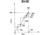
つぎに、この発明の本実施の形態にかかるサーバにおける最適なリソース消費について説明する。第8図〜第10図は、本実施の形態にかかるサーバ・クライアント・システムのサーバにおける最適なリソース消費の一例を表す説明図である。第8図において、CPUの消費量をX座標、メモリの消費量をY座標として示している。第8図および後述する第9図、第10図では、サーバ101d〜101fのサーバがある場合、それぞれのサーバによって消費可能なリソースの量が異なることを示している。 Next, optimal resource consumption in the server according to the embodiment of the present invention will be described. 8 to 10 are explanatory diagrams showing an example of optimal resource consumption in the server of the server-client system according to the present embodiment. In FIG. 8, the CPU consumption is shown as an X coordinate and the memory consumption is shown as a Y coordinate. FIG. 8 and FIGS. 9 and 10 to be described later show that when there are
まず、第8図のグラフの特徴は、サーバ101dが備えたものとして説明をおこなう。このグラフでは、CPU消費量の最大値である100%に当たる量を最大値801にて表している。これは、後述する第9図のCPU消費量の最大値の80%を表し、さらに、第10図のCPU消費量の最大値の50%を表す。そして、メモリ消費量の最大値である100%に当たる量を最大値802として表している。これは、後述する第9図のメモリの消費量の最大値と同じ量を表し、さらに、第10図のメモリの消費量の最大値の2倍となる200%を表す。 First, the characteristics of the graph of FIG. 8 will be described assuming that the
そして、第8図のグラフに示すように、最初に起動されたプロセス803が原点の位置から記載され、プロセス803に続いて起動されるプロセスがプロセス804〜808まで時系列に階段状に記載されて、最終的にはCPU消費量の最大値801とメモリ消費量の最大値802との交点となる座標809に到達する。このことによって、サーバ101dはCPUとメモリが理想的に消費された状態となっている。 Then, as shown in the graph of FIG. 8, the
第9図において、グラフは、CPUの消費量をX座標、メモリの消費量をY座標として示している。第9図では第8図と同様、サーバ101d〜101fのサーバがある場合、それぞれのサーバにより消費できるリソースの量に違いがあることを示している。 In FIG. 9, the graph shows the CPU consumption as the X coordinate and the memory consumption as the Y coordinate. FIG. 9 shows that when there are
第9図に示すグラフの特徴は、サーバ101eが備えたものとして以下説明をおこなう。このグラフではCPU消費量の最大値である100%に当たる量を最大値901として表している。これは、前述した第8図のCPU消費量の最大値の125%を表し、さらに、後述する第10図のCPU消費量の最大値の62.5%を表す。 The characteristics of the graph shown in FIG. 9 will be described below assuming that the server 101e is equipped. In this graph, an amount corresponding to 100%, which is the maximum value of CPU consumption, is represented as a
つぎに、メモリ消費量の最大値である100%に当たる量を最大値902として表している。これは、前述した第8図のメモリの消費量の最大値と同じ量を表し、さらに、後述する第10図のメモリの消費量の最大値の2倍となる。 Next, an amount corresponding to 100%, which is the maximum value of memory consumption, is represented as a
そして、第9図のグラフに示すように、最初に起動されたプロセス903が原点の位置から記載され、プロセス903に続いて起動されるプロセスがプロセス904〜908まで時系列に階段状に記載されていき、最終的にはCPU消費量の最大値901とメモリ消費量の最大値902との交点となる座標909に到達する。このことにより、サーバ101eはCPUとメモリが理想的に消費された状態となっている。 Then, as shown in the graph of FIG. 9, the
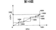
第10図において、CPUの消費量をX座標、メモリの消費量をY座標として示している。第10図では第8図、第9図と同様、サーバ101d〜101fのサーバがある場合、それぞれのサーバにより消費できるリソースの量に違いがあることを示している。 In FIG. 10, the CPU consumption is shown as an X coordinate and the memory consumption is shown as a Y coordinate. FIG. 10 shows that when there are
第10図に示すグラフの特徴は、サーバ101fが備えたものとして以下説明をおこなう。このグラフではCPU消費量の最大値である100%に当たる量を最大値1001として表している。これは、前述した第8図のCPU消費量の最大値の200%を表し、さらに、第9図のCPU消費量の最大値の160%を表す。そして、メモリ消費量の最大値である100%に当たる量を最大値1002として示し、この最大値1002は、前述した第8図および第9図のメモリの消費量の最大値の50%となっている。 The characteristics of the graph shown in FIG. 10 will be described below assuming that the server 101f is provided. In this graph, an amount corresponding to 100%, which is the maximum value of CPU consumption, is represented as a
そして、第10図のグラフに示すように、最初に起動されたプロセス1003が原点の位置から記載され、プロセス1003に続いて起動されるプロセスがプロセス1004〜1008まで時系列に階段状に記載されていき、最終的にはCPU消費量の最大値1001とメモリ消費量の最大値1002との交点となる座標1009に到達する。このことにより、サーバ101fはCPUとメモリが理想的に消費された状態となっている。 Then, as shown in the graph of FIG. 10, the
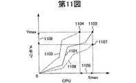
つぎに、この発明の本実施の形態にかかるサーバのリソース消費例について説明する。第11図は、この発明の本実施の形態にかかるサーバのリソース消費例を示す説明図である。第11図において、X座標上のXmaxは、CPU消費量の最大値となる100%が示され、Y座標上のYmaxは、メモリ消費量の最大値となる100%が示されている。 Next, an example of server resource consumption according to this embodiment of the present invention will be described. FIG. 11 is an explanatory diagram showing an example of resource consumption of the server according to this embodiment of the present invention. In FIG. 11, Xmax on the X coordinate indicates 100%, which is the maximum value of CPU consumption, and Ymax on the Y coordinate indicates 100%, which is the maximum value of memory consumption.
折れ線1101は、CPUおよびメモリのリソースを各プロセスの発生ごとに割り当て、最終的にCPU消費量の最大値であるXmaxと、メモリ消費量の最大値であるYmaxとの交点の座標1102に到達した例を示す。これにより、折れ線1101が、CPUとメモリの消費量に無駄が無いプロセスの割り当てがおこなわれた場合のグラフであることを示し、リソースが理想的に消費された結果を表している。 A
折れ線1103は、CPUおよびメモリのリソースを各プロセスの発生ごとに割り当てた結果、CPU消費量がその最大値であるXmaxに達する前にメモリ消費量が最大値であるYmaxに到達した例を示している。このことは、折れ線1103が、メモリの消費量に対してCPUの消費量に無駄ができた場合のグラフであることを示し、区間1105が示す量だけ使用可能なCPUが残ったことを示している。 A
折れ線1106は、CPUおよびメモリのリソースを各プロセスの発生ごとに割り当てた結果、メモリ消費量がその最大値であるYmaxに達する前にCPU消費量が最大値であるXmaxに到達した例を示している。このことは、折れ線1106が、CPUの消費量に対してメモリの消費量に無駄ができた場合のグラフであることを示し、区間1108が示す量だけ使用可能なメモリが残ったことを示している。 A
従来の負荷分散装置によるプロセスの割り当て方は、サーバのリソース消費量を判断せずに負荷分散をおこなうため、前述した折れ線1103,1106にて示したような、リソースが均等に消費されない状態となるのが通常である。これに対してリソースであるCPUとメモリとが均等に消費されるようなプロセスの割り当てがおこなわれると、折れ線1101のように、消費されない無駄なリソースが残ることを防止することができる。 In the conventional process of assigning processes by the load balancer, load distribution is performed without determining the resource consumption of the server, so that the resources are not consumed evenly as indicated by the above-mentioned
(サーバの評価方法)
つぎに、この発明の本実施の形態にかかる負荷分散装置によるサーバの評価方法について説明する。第12図は、この発明の本実施の形態にかかる負荷分散装置によるサーバの評価方法の概要を示す説明図である。第12図において、グラフ1202,1203は、CPUの消費量をX座標、メモリの消費量をY座標として示している。以下、グラフ1202はサーバ101bのリソース消費の内容を示し、グラフ1203はサーバ101cのリソース消費の内容を示すものである。(Server evaluation method)
Next, a server evaluation method by the load distribution apparatus according to this embodiment of the present invention will be described. FIG. 12 is an explanatory diagram showing an outline of a server evaluation method by the load distribution apparatus according to the embodiment of the present invention. In FIG. 12,
まず、グラフ1202はグラフ1203と比較して、CPU消費量の最大値が2倍とメモリ消費量の最大値が1/2倍のリソースを備えたサーバの特性を示している。グラフ1202にはプロセス1204,1205が既に割り当てられ実行されている。一方、グラフ1203はグラフ1202と比較してCPU消費量の最大値が1/2倍とメモリ消費量の最大値が2倍のリソースを備えたサーバの特性を示している。グラフ1203にはプロセス1210,1211が既に割り当てられ実行されている。以下では、プロセス1201の実行要求が発生した場合、プロセス1201を、グラフ1202またはグラフ1203のいずれの特性を備えたサーバに負荷分散すると最適にリソースが消費されるかを判断する方法を説明する。 First, a
グラフ1203にてプロセス1201を実行させた場合、プロセス1211の頂点1211aからプロセス1201分のリソース消費量が加わることにより、消費されるリソース全体を表す座標(消費リソース座標)は座標1215となる。そして、CPUおよびメモリの消費量の最大値との交点の座標1213と原点とを結んだ直線をリソース消費最適線1212(以下、CPUおよびメモリの消費量の最大値からなる交点の座標と、原点とを結んだ直線をリソース消費最適線と呼ぶ)とし、座標1215からこのリソース消費最適線1212に対して垂線1214を引く。 When the
一方、グラフ1202にてプロセス1201を実行させた場合、プロセス1205の頂点1205aからプロセス1201分のリソース消費量が加わることにより、消費されるリソース全体を表す座標(消費リソース座標)は座標1209となる。そして、CPUおよびメモリの消費量の最大値との交点の座標1207と原点とを結んだ直線をリソース消費最適線1206とし、座標1209からこのリソース消費最適線1206に対して垂線1208を引く。 On the other hand, when the
そして、垂線1208と、垂線1214との長さを比較すると、垂線1208の長さの方が短くなることが示される。このことは、プロセス1201を、サーバ101cにて実行させるより、サーバ101bにて実行させた方が、サーバ101bのリソースであるメモリの消費量とCPUの消費量のバランスが均等に近くなることを示している。よって、プロセス1201を実行させるサーバとして、グラフ1203の特性を備えたサーバ101cが選択されず、グラフ1202の特性を備えたサーバ101bが選択される。サーバ101bにてプロセス1201が実行されると、リソースが最適に消費されることになる。 Then, comparing the lengths of the
このとき、垂線1208と1214の長さが等しく、どちらのサーバが選択された場合も同様にリソースがより適切に消費されると判断できる場合も存在し得る。このような場合には、消費リソース座標1209、1215と原点との距離1216と1217を比較し、その長さの短いサーバを割り当てる。このようにすることで、リソース消費最適線との距離が同様のサーバが存在した場合によりリソース消費量が小さいサーバを割り当てることが可能となる。加えて、リソース消費量とリソース消費最適線からの距離の両方を同時に加味したい場合は垂線(1208、1214)と原点との距離(1216、1217)を乗じた面積(1208×1216、1214×1217)がより小さい値を持つサーバを選択することによって実現できる。 At this time, there may be a case where the lengths of the
つぎに、この発明の本実施の形態にかかる割り当てサーバの評価方法の関数について説明する。第13図は、この発明の本実施の形態にかかる割り当てサーバの評価方法の関数の一例を示す説明図である。第13図において、X座標上のXmaxは、CPU消費量の最大値となる100%が表され、Y座標上のYmaxは、メモリ消費量の最大値となる100%が表されている。そして、リソースのパラメータを軸とした空間上で原点とパラメータの使用可能な最大容量、すなわちXmaxとYmaxとの交点の座標を(xmax,ymax)とし、(xmax,ymax)と原点(0,0)とを結んだ直線をリソース消費最適線1301とする。なお、第13図に示すグラフの特徴は、サーバ101bが備えたものとして以下説明をおこなう。Next, functions of the allocation server evaluation method according to the embodiment of the present invention will be described. FIG. 13 is an explanatory diagram showing an example of a function of the allocation server evaluation method according to the embodiment of the present invention. In FIG. 13, Xmax on the X coordinate represents 100%, which is the maximum value of CPU consumption, and Ymax on the Y coordinate represents 100%, which is the maximum value of memory consumption. Then, in the space with the resource parameter as an axis, the maximum capacity of the origin and the parameter, that is, the coordinates of the intersection of Xmax and Ymax is (xmax , ymax ), and (xmax , ymax ) and the origin A straight line connecting (0, 0) is a resource
まず、1つ目に実行中のプロセス1302は、プロセス1302によって消費されるメモリの消費量とCPUの消費量とを縦横の各辺の長さとした原点からの矩形として示される。これは、各プロセスが消費するリソースを表す矩形としたものである。このプロセス1302によって表される矩形の原点からの対角の頂点は座標1302aとして示される。 First, the
実行中の2つ目のプロセス1303は、座標1302aを開始点とし、プロセス1303によって消費されるメモリの消費量とCPUの消費量とを縦横の各辺の長さとした矩形として示すことができる。この矩形の開始点である座標1302aからの対角の頂点は座標1303aとして示される。 The
そして、新たに割り当てる3つ目のプロセスが、プロセス1304である場合、座標1303aを開始点とし、CPUの使用量をcx、メモリの使用量をcyとした矩形として第13図のように示される。矩形の開始点である座標1303aの対角を示す頂点は座標1304aとして示される。
つぎに、座標1304aからリソース消費最適線1301に対して下ろす垂線1309の距離を求める。まず、第13図のグラフ上に示されるxおよびyの位置の値は以下の式(1)、式(2)にて表される。The third process newly allocated is when the
Next, the distance of the perpendicular 1309 to be drawn from the coordinate 1304a to the resource
y=fxy(x)=(ymax/xmax)×x・・・(1)
x=fyx(y)=(xmax/ymax)×y・・・(2)y = fxy (x) = (ymax / xmax ) × x (1)
x = fyx (y) = (xmax / ymax ) × y (2)
前述したように、1つ目のプロセス1302と2つ目のプロセス1303とが消費する消費リソース座標は座標1303aによって示されている。そして、3つ目のプロセスが消費する消費リソース座標は座標1304aとして示している。この座標1304aの座標は(x1,y1)=(x0+cx,y0+cy)として表される。As described above, the consumed resource coordinates consumed by the
一方、縦軸と並行な座標1304aを通る直線と、リソース消費最適線1301との交点を座標1305とする。また、横軸と並行な座標1304aを通る直線と、リソース消費最適線1301との交点を座標1306とする。座標1304aと座標1305とを結ぶ直線を直線1307とし、直線1307の長さは以下の式(3)にて与えられる。 On the other hand, an intersection of a straight line passing through the coordinate 1304a parallel to the vertical axis and the resource consumption
Δy=|fxy(x1)−y1|・・・(3)Δy = | fxy (x1 ) −y1 | (3)
また、座標1304aと座標1306とを結ぶ直線を直線1308とし、直線1308の長さは以下の式(4)で与えられる。 A straight line connecting the
Δx=|fyx(y1)−x1|・・・(4)Δx = | fyx (y1 ) −x1 | (4)
座標1304aからリソース消費最適線1301へ引く垂線を垂線1309とし、垂線1309の長さは以下の式(5)にて与えられる。 A perpendicular drawn from the coordinate 1304a to the resource
disxy=ΔxΔy/√(Δx2 + Δy2)・・・(5)disxy = ΔxΔy / √ (Δx2 + Δy2 ) (5)
このdisxyが、座標1304aのリソース消費最適線1301からの距離であり、負荷分散装置101aが複数のサーバの中からプロセスを実行させるためのサーバを決定するときに評価する値となる。This disxy is the distance from the optimal
そして、つぎに、前述したCPUとメモリ以外にも他のパラメータを含むn次元関数の場合の消費リソース座標からリソース消費最適線への距離を求める式の説明をおこなう。まず、リソースとして用いるパラメータがn個(xi)(1≦i≦n)のn次ユークリッド空間上で求めることができるリソース消費最適線は、2次元の場合を用いて以下の式(6)にて表される(1≦i≦n)。Next, an expression for obtaining the distance from the resource consumption coordinate to the resource consumption optimum line in the case of an n-dimensional function including other parameters besides the CPU and memory described above will be described. First, a resource consumption optimum line that can be obtained on an n-order Euclidean space with n (xi ) (1 ≦ i ≦ n) parameters used as resources is expressed by the following equation (6) using a two-dimensional case. (1 ≦ i ≦ n).
xi+1=fxi x(i+1)mod n(xi)=(x(i+1)mod n max/xi max)×xi
・・・(6)x i + 1 = f xi x (i + 1) mod n (x i) = (x (i + 1) mod n max / x i max) × x i
... (6)
現在のサーバのリソースの消費量を(xi0)(1≦i≦n)、プロセスのリソースの使用量を(ci)(1≦i≦n)としたとき、When the current server resource consumption is (xi0 ) (1 ≦ i ≦ n) and the process resource usage is (ci ) (1 ≦ i ≦ n),
xi1=xi0+ci・・・(7)xi1 = xi0 + ci (7)
このとき、式(8)を、 At this time, Equation (8) is
Δx(i+1)mod n=|fxi x(i+1)mod n(xi1)−x(i+1)mod n 1|
・・・(8)Δx (i +1 )mod n = | fxi x (i + 1) mod n (xi1 ) −x (i +1 )mod n 1 |
... (8)
とし(1≦i≦n)、n次元ユークリッド空間上での点(xi1)(1≦i≦n)とリソース消費最適線1301との距離は以下の式(9)のように表記できる。(1 ≦ i ≦ n), the distance between the point (xi1 ) (1 ≦ i ≦ n) on the n-dimensional Euclidean space and the resource

したがって、負荷分散装置101aは、負荷分散の対象となるサーバ101b〜101nのそれぞれの式(5)あるいは式(9)にて示される距離(dis)を算出し、その距離が最も短いサーバに対してプロセスの実行処理を割り当てる。 Therefore, the
また、n次元ユークリッド空間上での点(xi1)(1≦i≦n)と原点との距離1310は式(10)のように表記できる。Further, the
したがって垂線の長さdisが等しいサーバの中から1つを選択する場合にはdiagの値が小さいものを選択し、プロセスの実行処理を割り当てる。さらに垂線の長さdisと原点との距離diagを同時に評価したい場合にはdis×diagの値が最も小さいサーバに対して処理を割り当てる。 Therefore, when one server is selected from the servers having the same vertical line length dis, the server having the smaller diag value is selected and the process execution process is assigned. Furthermore, when it is desired to simultaneously evaluate the length dis of the perpendicular line and the distance diag between the origin, processing is assigned to the server having the smallest value of dis × diag.
なお、前述したCPUとメモリ以外のリソースとは、たとえば、GPUやビデオメモリ、ネットワークインターフェースカードなどである。GPUは、3Dグラフィックを利用するゲームにてレンダリングやジオメトリ演算をハードウエアにておこなうためのグラフィックチップである。また、ビデオメモリは、GPUが画像処理の演算をおこなう際に使用するGPU内に備えるメモリである。また、ネットワークインターフェースカードは、例えばイーサネット(登録商標)アダプタであり、100Base、1000Base−TX等を終端するものである。 The above-mentioned resources other than the CPU and memory are, for example, a GPU, a video memory, a network interface card, and the like. The GPU is a graphic chip for performing rendering and geometry calculation by hardware in a game using 3D graphics. The video memory is a memory provided in the GPU used when the GPU performs image processing calculations. The network interface card is an Ethernet (registered trademark) adapter, for example, and terminates 100Base, 1000Base-TX, and the like.
つぎに、この発明の本実施の形態にかかる負荷分散装置によるサーバの評価および決定の処理の内容について説明する。第14図は、この発明の本実施の形態にかかる負荷分散装置によるサーバの評価および決定の処理手順の一例を示すフローチャートである。第14図のフローチャートにおいて、まず、負荷分散装置101aがサーバ101b〜101nを評価するときに用いるパラメータを設定する(ステップS1401)。パラメータは、たとえば、CPUの消費量や、メモリの消費量や、GPUの消費量や、GPUの備えるビデオメモリの消費量や、ネットワークインターフェースカードの帯域消費量などである。 Next, the contents of server evaluation and determination processing by the load balancer according to the embodiment of the present invention will be described. FIG. 14 is a flowchart showing an example of a server evaluation and determination processing procedure by the load distribution apparatus according to the embodiment of the present invention. In the flowchart of FIG. 14, first, parameters used when the
つぎに、複数のプロセスの実行時にそれぞれが使用するリソースの使用量を、各パラメータごとに定義して設定する(ステップS1402)。そして、サーバ101b〜101nごとに、ステップS1402にて定義したパラメータであるリソースの最大値の設定をおこなう(ステップS1403)。 Next, the usage amount of the resource used by each of the plurality of processes is defined and set for each parameter (step S1402). Then, for each of the
つぎに、ステップS1401にて設定した各パラメータのリソース消費量について、サーバ101b〜101nごとに取得し、監視する(ステップS1404)。クライアントである端末装置102や携帯電話機103からプロセス実行の要求が有ったか否かを判断する(ステップS1405)。プロセス実行の要求が無かった場合(ステップS1405:No)にはステップS1404に戻り、サーバ101b〜101nの各サーバごとに消費されたリソースの消費量を監視する(ステップS1404)処理を引き続きおこなう。 Next, the resource consumption of each parameter set in step S1401 is acquired and monitored for each of the
一方、クライアントである端末装置102からプロセス実行の要求が有った場合(ステップS1405:Yes)には、このプロセスを実行するためのサーバの候補をサーバ101b〜101nの中から選択する(ステップS1406)。これは、ステップS1401にて設定したパラメータのいずれについてもその使用量が最大値を超えないサーバをサーバ101b〜101nの中から選択するものである。そして、ステップS1406にて選択された候補の中から、さらに、先述した第13図の消費リソース座標1304aからリソース消費最適線1301に下ろす垂線1309の距離を求めることで評価をおこない、距離が一番短い、たとえば、サーバ101bを負荷分散先として決定する(ステップS1407)。 On the other hand, if there is a process execution request from the
また、S1406のサーバ候補の選択では前述のように消費リソース座標1304aからのリソース消費最適線1301に下ろす垂線1309の長さに加え、消費リソース座標1304aと原点との距離1310を合わせて評価することができる。垂線1309の長さが等しいサーバが存在した場合には原点との距離1310が小さいサーバを選択することでよりリソース消費量の小さいサーバを選択できる。あるいは垂線1309の長さと原点との距離1310をかけ合わせた値の最も小さいサーバを選択することで、最適なリソース消費を実現し、かつリソース消費量が小さいサーバにプロセスを割り当てることができる。 Further, in the selection of server candidates in S1406, as described above, in addition to the length of the perpendicular 1309 drawn from the resource consumption coordinate 1304a to the resource
負荷分散装置101aは、ステップS1407にて決定した負荷分散先のサーバ101bに対し、プロセスの実行要求をおこなう(ステップS1408)。そして、クライアントである端末装置102に対してプロセスが実行されたことを示すため、負荷分散先のサーバ101bにアクセスするための情報であるIPアドレスやサービスポート番号などの通知をおこなう(ステップS1409)。サーバ101bへアクセスするための情報を通知された端末装置102は、サーバ101bへ直接アクセスすることが可能となり、処理を終了する。 The
つぎに、この発明の本実施の形態にかかる負荷分散装置によるサーバの評価および決定の処理手順の内容について説明する。第15図は、この発明の本実施の形態にかかる負荷分散装置によるサーバの評価および決定の処理手順の一例を示す概要図である。第15図において、負荷分散装置101aは、端末装置102a〜102nから要求されるプロセスの実行を、サーバ101b〜101nに対して負荷分散することが示される。第15図において、負荷分散装置101aは、以下の手順により処理をおこなう。 Next, the contents of the server evaluation and decision processing procedures by the load balancer according to the embodiment of the present invention will be described. FIG. 15 is a schematic diagram showing an example of a server evaluation and determination processing procedure by the load distribution apparatus according to the embodiment of the present invention. FIG. 15 shows that the
(1)負荷分散をおこなう際の評価に用いるパラメータを設定する。
(2)各サーバにて実行されるプロセスが消費する各パラメータごとの使用量を定義し、設定する。この設定は、新しいプロセスが追加されるたびにおこなう。たとえば、CPU、メモリ、GPU、ビデオメモリ、の4つのパラメータを使用する場合、実行されるプロセスが3Dゲームであれば、CPUとメモリに加え、GPUとビデオメモリについてもリソースが消費される。また、実行されるプロセスが2Dゲームであれば、GPUとビデオメモリのリソースは消費されない。このようにプロセスの内容によって消費されるリソースは異なる。(1) Set parameters used for evaluation when performing load distribution.
(2) Define and set the usage for each parameter consumed by the processes executed on each server. This is done every time a new process is added. For example, when four parameters of CPU, memory, GPU, and video memory are used, if the process to be executed is a 3D game, resources are consumed for the GPU and video memory in addition to the CPU and memory. Further, if the process to be executed is a 2D game, GPU and video memory resources are not consumed. In this way, the resources consumed vary depending on the contents of the process.
(3)各サーバごとに備える各パラメータの最大値の設定をおこなう。この設定は、管理者などにより負荷分散装置101aに対し手作業にて設定してもよいし、あるいは、各サーバをネットワーク100を介して順にモニタリングし、設定値を取得させるようにしてもよい。また、ゲームや他のアプリケーションサーバなど、その使用目的に応じて多様なサーバ101b〜101nが設置される可能性があるため、個々のパラメータに最大容量を設定できるようにする。この処理は矢印1501aにて示される。 (3) The maximum value of each parameter provided for each server is set. This setting may be set manually by the administrator or the like with respect to the
(4)パラメータとして設定したリソースについて、サーバ101b〜101nの各サーバごとに消費された量を監視する。この処理は、矢印1501aにて示されるもので、負荷分散装置101aからサーバ101b〜101nに対して順にモニタリングをおこない、消費量を取得する。 (4) With respect to the resources set as parameters, the amount consumed for each of the
(5)クライアントである端末装置102aからプロセス実行の要求を受け付ける。それと同時に、受け付けたプロセスが使用する各リソースの量を取得する。この処理は矢印1502にて示される。 (5) A process execution request is received from the
(6)負荷分散装置101aは、プロセスを実行するためのサーバの候補をサーバ101b〜101nの中から選択する。実行要求を受け付けたプロセスが使用するリソースの消費量が、各サーバのリソースの最大値を超えていないかをチェックし、超えていないものを候補として選択する。 (6) The
(7)負荷分散装置101aは、(6)で選択された候補の中から、さらに、先述した第13図の消費リソース座標1304aからリソース消費最適線1301に下ろす垂線1309の距離あるいは消費リソース座標1304aと原点との距離1310を求めることで評価をおこない、垂線の長さが一番短い、あるいは垂線の長さが同じ場合は原点からの距離1310が短い、あるいは垂線の長さと原点からの距離を乗じた値が最も小さい、たとえば、サーバ101bを負荷分散先として決定する。 (7) The
(8)負荷分散装置101aは、ステップS1407にて決定した負荷分散先のサーバ101bに対し、プロセスの実行要求をおこなう。このとき、サーバ101bが実行要求を認証済みクライアントからのアクセスのみ受け付ける場合には、端末装置102aからID、IPアドレス、サービスポート番号、暗号化の鍵、トークンなどもサーバ101bへ送信する。この処理は、矢印1501aにて示される。 (8) The
(9)クライアントである端末装置102aに対してプロセスが実行されたことを示すため、負荷分散先のサーバ101bの情報の通知をおこなう。この情報とは、端末装置102aがサーバ101bへアクセスするときに必要とする。たとえば、端末装置102aがサーバ101bへ直接アクセスする際には、サーバ101bのIPアドレス、ポート番号、認証・暗号化に関わる鍵やトークンを指す。この処理は、矢印1502にて示される。 (9) In order to indicate that the process has been executed to the
(10)サーバ101bへアクセスするための情報を通知された端末装置102aは、サーバ101bへアクセスすることが可能となる。(9)にて通知を受けた情報に基づき、端末装置102aからサーバ101bへアクセスすることが可能となる。サーバ101b側では、認証されたクライアントからのアクセスか否かをIPアドレスやIDやトークンなどが一致しているかによって確認する。暗号化鍵が受け渡しされている場合には通信が暗号化される。この処理は、矢印1503にて示される。 (10) The
(プロセスの情報の内容)
つぎに、この発明の本実施の形態にかかる負荷分散装置が保持するプロセスの情報について説明する。第16図は、この発明の本実施の形態にかかるプロセスの情報を保持するテーブルの一例を示す説明図である。第16図において、プロセス情報テーブル1600は、プロセスの情報を保持するためのデータ内容を格納しており、プロセスを一意に識別するためのIDと、プロセスの名称であるプロセス名と、プロセスが実行の際に使用するCPUの使用量と、プロセスが実行の際に使用するメモリの使用量との各項目からなる。(Content of process information)
Next, process information held by the load balancer according to the embodiment of the present invention will be described. FIG. 16 is an explanatory diagram showing an example of a table holding process information according to the embodiment of the present invention. In FIG. 16, a process information table 1600 stores data contents for holding process information, an ID for uniquely identifying the process, a process name that is the name of the process, and a process executed by the process Each item includes a CPU usage amount used in the process and a memory usage amount used when the process is executed.
IDのデータ属性はテキスト型、あるいは数値だけで表すことができる場合には整数型などとする。プロセス名のデータ属性はテキスト型などとし、CPUの使用量と、メモリの使用量のデータ属性は、浮動小数点型などの属性として定義する。 The data attribute of the ID is a text type or an integer type if it can be expressed only by a numerical value. The data attribute of the process name is a text type, and the data attribute of the CPU usage and the memory usage is defined as an attribute such as a floating point type.
まず、IDが100のレコードが示すプロセスのデータ内容は、プロセス名がプロセス1、CPUの使用量が0.15、メモリの使用量が0.2である。つぎに、IDが110のレコードが示すプロセスのデータ内容は、プロセス名がプロセス2、CPUの使用量が0.2、メモリの使用量が0.4であり、CPUとメモリの使用量についてはIDが100の場合も同様である。これは、IDが100あるいは110のプロセスをそれぞれ実行した場合に、実行されたサーバにて消費されるCPUとメモリの消費量の値が、それぞれテーブルに登録されたCPUとメモリの使用量の数値分だけ増加することを示す。 First, the data content of the process indicated by the record whose ID is 100 is that the process name is
負荷分散装置101aは、端末装置102からプロセスの実行の要求を受けると、プロセス情報テーブル1600のプロセス情報を利用し、負荷を分散するためのサーバを選択する。なお、分散するためのサーバ101b〜101nの数が少ない場合などは、上述したテーブルのようなデータベースを使ったテーブル管理をせず、テキストファイルなどによる参照用のファイルに記述しておく方が手間が少ない場合がある。そのような場合は、テーブル内容を必要に応じて参照用ファイルとして作成し、そのフォーマットも任意に決めることができるものとする。 When receiving a process execution request from the
(テーブルの情報)
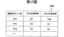
つぎに、この発明の本実施の形態にかかる負荷分散装置が保持するサーバ情報について説明する。第17図は、この発明の本実施の形態にかかるサーバ・クライアント・システムのサーバの情報を保持するテーブルの一例を示す説明図である。第17図において、サーバ情報テーブル1700は、サーバの情報を保持するためのデータを格納しており、サーバを一意に識別するための接続先サーバ名と、各サーバで使用中のCPUの使用率と、各サーバで使用中のメモリの使用率との各項目からなる。(Table information)
Next, server information held by the load balancer according to the embodiment of the present invention will be described. FIG. 17 is an explanatory diagram showing an example of a table for holding server information of the server / client system according to the embodiment of the present invention. In FIG. 17, a server information table 1700 stores data for holding server information, and includes a connection destination server name for uniquely identifying the server, and a CPU usage rate used by each server. And the usage rate of the memory being used in each server.
接続先サーバ名のデータ属性はテキスト型、あるいは、数値だけで表される場合には整数型などとする。CPUの使用率およびメモリの使用率のデータ属性は、浮動小数点型とする。ここで、サーバ情報テーブル1700に示されるCPUあるいはメモリの使用率とは、サーバ101a,101b,101cのそれぞれで既に使用されているCPUあるいはメモリの割合を数値として表したものである。なお、サーバ101b,101c,101dにおけるCPUおよびメモリの使用率の最大値は1.0(=100%)とする。負荷分散装置101aは、これらの値を各サーバから定期的にモニタリングしてテーブルにセットしたり、あるいは、負荷分散をおこなう際に必要に応じて取得したりしてもよい。そして、以下では、第16図に示したIDが100のプロセス1を、サーバ101b,101c,101dのいずれのサーバに負荷分散するかについての評価をおこなう。 The data attribute of the connection destination server name is a text type or an integer type if it is expressed only by a numerical value. The data attribute of the CPU usage rate and the memory usage rate is a floating point type. Here, the CPU or memory usage rate shown in the server information table 1700 is a numerical value representing the percentage of the CPU or memory already used in each of the
まず、サーバ情報テーブル1700の1段目に示す接続先サーバ名が101bのレコードは、既に使用されているCPUの使用率が0.9で、メモリの使用率は0.88である。このサーバ101bはCPUおよびメモリともに使用率が高く、第16図に示したプロセス1のCPUの使用量およびメモリの使用量を加算すると、それぞれ最大値の1.0(=100%)を超えるため、既にプロセス1を実行させるためのリソースの空きが無いことが分かる。 First, the record of the connection
2段目に示す接続サーバ名が101cのレコードは、CPUの使用率が0.5で、メモリの使用率が0.2である。このサーバ101cに、第16図に示したプロセス1のCPUの使用量およびメモリの使用量を加算した場合、CPUの使用率が0.65、メモリの使用率が0.4となるため、ともに1.0(=100%)未満であり、プロセス1を実行させるためのリソースの空きがあることが分かる。 The record with the
3段目に示す接続サーバ名が101dのレコードは、CPUの使用率が0.3で、メモリの使用率が0.2である。このサーバ101dに、第16図に示したプロセス1のCPUの使用量およびメモリの使用量を加算した場合、CPUの使用率が0.45、メモリの使用率が0.4となるため、ともに1.0(=100%)未満であり、プロセス1を実行させるためのリソースの空きがあることが分かる。 The
さらに、式(5)を用いて、これらサーバ101cとサーバ101dの消費リソース座標からリソース消費最適線へ下ろす垂線の距離disをそれぞれ求めると、サーバ101cでの距離は約0.177となり、サーバ104cでの距離は約0.035となる。これにより、負荷分散装置101aは、距離の短いサーバ101dを最適なサーバとして選択し、割り当てる。 Further, using the equation (5), when the distances dis of the perpendiculars to the resource consumption optimal line from the consumption resource coordinates of the
また、消費リソース座標と原点との距離diagについては、式(10)よりサーバ101cが約0.763、サーバ101dが約0.602となり、両者の積(dis×diag)の値はサーバ101cの場合約0.135、サーバ101dの場合約0.021となり、リソース消費最適線の長さ、消費リソース座標と原点との距離の両者を同時に考慮した場合でもサーバ101dを最適なサーバに選択し、割り当てる。 Further, the distance diag between the consumed resource coordinates and the origin is about 0.763 for the
なお、負荷を分散するためのサーバが、サーバ101b,101c,101dといった数が少ない場合には、上述のようなデータベースを使ったテーブル管理をせず、テキストファイルなどによる参照用のファイルに記述し、更新させる方が手間が少ない場合がある。そのような場合は、第17図に示したテーブル内容を必要に応じてテキストファイルとして書き出してもよく、そのフォーマットは任意に決めて作成してよいものとする。また、図示していないが、上述したCPUやメモリの使用率だけでなく、各サーバにアクセスするためのIPアドレスやポート番号などの項目も必要に応じてセットしてもよい。 If there are a small number of
(サーバの地域分散の内容)
つぎに、この発明の本実施の形態にかかる地域ごとに管理されるサーバの負荷分散について説明する。第18図は、この発明の本実施の形態にかかるサーバ・クライアント・システムのサーバの地域分散の一例を示す説明図である。第18図において、地域Aには端末装置102aと、負荷分散装置1801aと、センタ1803に設置されるサーバ1803a〜1803nとが設置され、地域Bには端末装置102bと、負荷分散装置1801bと、センタ1804に設置されるサーバ1804a〜1804nとが設置され、店舗Cには端末装置102cと、負荷分散装置1801cと、センタ1805に設置されるサーバ1805a〜1805nとが設置される。これらにより、地域あるいは店舗ごとに分散された各装置を用いた複合的なサーバ・クライアント・システムの一例を示す。(Contents of regional distribution of servers)
Next, load distribution of servers managed for each area according to the embodiment of the present invention will be described. FIG. 18 is an explanatory diagram showing an example of regional distribution of servers in the server / client system according to the embodiment of the present invention. In FIG. 18, a
地域Aに設置される端末装置102aからのプロセス実行要求の流れを示すlineA1は、ユーザナビゲーション1802によりlineA2を通じて負荷分散装置1801aに送信される。ここで、ユーザナビゲーション1802とは、クライアントのIPアドレスから地域を判別してルーティングしたり、ローカルのDNSサーバのアドレスから各地域を判別してルーティングをおこなうシステムをいう。これにより、クライアントの各地域を特定し、クライアントに最も近い(ネットワーク的にデータ伝送の遅延が小さい)地域に設置されたサーバを優先的に割り当てることができる。そして、lineA2を通じて負荷分散装置1801aに送信されたプロセスの実行要求は、lineA3を通じて同じ地域Aに設置されるサーバ1803aに負荷分散し、プロセスの実行要求を送信する。 The line A1 indicating the flow of the process execution request from the
また、地域Bに設置される端末装置102bからのプロセス実行要求を示すlineB1は、ユーザナビゲーション1802によりlineB2を通じて負荷分散装置1801bに送信される。ここで、通常は地域B内に設置されたサーバ1804a〜1804nのいずれかにプロセスの実行要求が送信される。しかし、負荷分散装置1801aと負荷分散装置1801bとが、配下のサーバ群のリソース監視情報を交換するような仕組みとした場合、lineB3を通じて他の地域Aに設置されたサーバ1803aに対して負荷分散させることができるようになる。また、負荷分散装置1801bによって地域A、Bおよび店舗Cの全てのサーバのリソースを監視させれば、地域Aに設置されたサーバ1803a以外にも他の全てのサーバの中から負荷分散させるサーバを選択させることができるようになる。 Also, line B1 indicating a process execution request from the
また、店舗Cに設置される端末装置102cからのプロセス実行要求を示すlineC1は、ユーザナビゲーション1802によりlineC2を通じて負荷分散装置1801cに送信される。負荷分散装置1801cでは、店舗C内のサーバ1805a〜1805nの中から負荷分散可能なものを評価する。しかし、端末装置102cと同じ店舗C内に割り当て可能なリソースを備えたサーバが無い場合は、lineC3を通じて隣の地域Bにあるサーバ1804nに負荷分散させ、充当させるようにすることができる。 Also, line C1 indicating a process execution request from the
また、ゲームなどを含む多くのインターネットアプリケーションへのアクセスは、時刻に応じてアクセス頻度が変動することが知られている。例えば夜10時にアクセスのピークを迎え、ピークの前後の例えば夜9時、11時のアクセス頻度がピーク時よりも何割か小さいアプリケーションを想定する。東西の時差を考慮した場合、前後1時間の地域に配備されたサーバは、ピーク時間帯を迎えている地域のサーバのリソースが枯渇していた場合に、余剰リソースとしてピーク時間帯のクライアントからのプロセス処理要求を受け付け処理するといった東西地域負荷分散が可能となる。赤道上でも平均的な1時間時差は1700km弱であり、伝播遅延によるラウンドトリップタイムは約17msである。ゲームなど、頻繁にサーバ、クライアント間の通信が行われるアプリケーションにおいても充分に活用できる遅延であり、時刻によってピークを迎えるアプリケーションを有効に負荷分散できる。 In addition, it is known that the access frequency of many Internet applications including games etc. varies depending on the time. For example, it is assumed that an application reaches an access peak at 10 o'clock and the access frequency at, for example, 9 o'clock and 11 o'clock before and after the peak is several percent smaller than the peak time. When considering the time difference between east and west, servers deployed in the 1 hour front and back area will be used as surplus resources from clients in the peak time zone if the resources of the server in the area that has reached the peak time zone are exhausted. The load distribution in the east and west, such as receiving and processing process processing requests, becomes possible. Even on the equator, the average hourly time difference is less than 1700 km, and the round trip time due to propagation delay is about 17 ms. This is a delay that can be fully utilized even in applications such as games where communication between the server and the client is frequently performed, and it is possible to effectively distribute the load of applications that reach their peak depending on the time.
なお、実行要求されたプロセスが消費するリソース容量さえ残っていれば、負荷分散先となるサーバは地域を問わずどこに設置されていても構わない。このことにより、一般的にあまりリソースの消費が激しくないWebサーバとして使用されているホスティングサーバや、各地にあるネットワークカフェなどに設置された複数のPCサーバなどのリソースを部分的に借り受け、負荷分散させるためのサーバとして契約することにより、冗長性を持った負荷分散をおこなうことができるようになる。 As long as the resource capacity consumed by the requested process remains, the load distribution destination server may be installed anywhere regardless of the region. As a result, resources such as a hosting server that is generally used as a Web server that consumes less resources and multiple PC servers installed in network cafes in various locations can be partially borrowed to distribute the load. By making a contract as a server for this purpose, it becomes possible to perform load balancing with redundancy.
以上説明したように、本実施の形態によれば、端末装置102から実行要求のあったプロセスの実行時のリソース消費量を用いて評価することにより、そのプロセスが実行可能なサーバをサーバ101b〜101nの中から選択することができるようになる。また、実行させるプロセスが新規追加あるいは修正されるごとに、最新のリソース消費量を登録することにより、プロセスの実行を常に最適なサーバに割り当てることができるようになる。そして、実行要求のあったプロセスのリソース消費量と、常に監視しているサーバ101b〜101nが備えているリソースの残量とを用いてサーバを選択するため、プロセスが消費するリソース量とサーバのリソース残量とがミスマッチすることを防止することができる。 As described above, according to the present embodiment, the
また、実行要求のあったプロセスのリソース消費量と、常に監視しているサーバ101b〜101nの備えるリソースの残量とを用い、サーバのリソースが無駄なく消費される関数にて評価することにより、リソースが無駄なく消費される最適なサーバを選択することができるようになる。そして、消費されるリソースの量がプロセスごとに異なるゲームやアプリケーションプログラムなどを実行させるサーバを、複数の中から柔軟に選択することができるようになる。 In addition, by using the resource consumption of the process that requested execution and the remaining amount of resources of the
また、備えるリソースの量が一様でない複数のサーバの中から、実行させたいプロセスが消費するリソースに合ったリソースの残量を持つサーバを柔軟に選択することができるようになる。これによって、理想的なサーバリソースの消費をおこなうことができ、複数のサーバ全体の同時処理プロセス(ゲーム数など)が最大化でき、各サーバの各リソースパラメータについて、無駄なく容量を使い切ることができる。 In addition, it is possible to flexibly select a server having a remaining amount of resources that matches a resource consumed by a process desired to be executed from among a plurality of servers having different amounts of resources. This makes it possible to consume ideal server resources, maximize the simultaneous processing processes (such as the number of games) across multiple servers, and use up the capacity of each server's resource parameters without waste. .
また、本実施の形態の負荷分散装置101aを使用すると、リソースの残量が不足してプロセスが実行できない、あるいは、プロセスがキューイングされてしまう可能性があるサーバなどに負荷分散されることを防ぐことができるので、プロセスの実行要求に対する待ち時間を減少させることができる。 In addition, when the
なお、本実施の形態で説明した負荷分散方法は、あらかじめ用意されたプログラムをパーソナル・コンピュータやワークステーション等のコンピュータで実行することにより実現することができる。このプログラムは、ハードディスク、フレキシブルディスク、CD−ROM、MO、DVD等のコンピュータで読み取り可能な記録媒体に記録され、コンピュータによって記録媒体から読み出されることによって実行される。またこのプログラムは、インターネット等のネットワークを介して配布することが可能な伝送媒体であってもよい。 Note that the load distribution method described in the present embodiment can be realized by executing a program prepared in advance on a computer such as a personal computer or a workstation. This program is recorded on a computer-readable recording medium such as a hard disk, a flexible disk, a CD-ROM, an MO, and a DVD, and is executed by being read from the recording medium by the computer. The program may be a transmission medium that can be distributed via a network such as the Internet.
以上のように、この発明にかかるサーバ・クライアント・システム、負荷分散装置、負荷分散方法および負荷分散プログラムは、負荷分散をおこなう先のサーバのリソースをバランスよく消費させるために有用であり、特に、ゲームなど多くのユーザから実行要求のあるプロセスを複数のサーバに割り当てる場合に適している。 As described above, the server / client system, the load distribution device, the load distribution method, and the load distribution program according to the present invention are useful for consuming the resources of the server to which the load is distributed in a balanced manner, It is suitable for assigning processes that have been requested by many users, such as games, to multiple servers.
Claims (8)
Translated fromJapanese前記サーバのうちの少なくともいずれか一つが、
前記クライアントから前記プロセスに関する情報を前記ネットワークを介して受信するプロセス情報受信手段と、
前記プロセス情報受信手段によって受信されたプロセスに関する情報に基づいて、前記複数のサーバの中から前記プロセスを処理させるサーバを決定する決定手段と、
前記決定手段によって決定されたサーバに関する情報を前記クライアントへ送信するサーバ情報送信手段と、
を備え、
前記クライアントは、
前記サーバ情報送信手段によって送信されたサーバに関する情報を前記ネットワークを介して受信するサーバ情報受信手段と、
前記サーバ情報受信手段によって受信された情報にかかるサーバへ、前記プロセス処理要求に関する情報を送信するプロセス要求送信手段と、
を備え、
前記決定手段は、
各サーバにおけるリソースのパラメータを軸とした空間上において、前記プロセスのリソース消費量を各サーバの現リソース消費量を表わす点に加えたことによって求められるリソース消費量の予想点の、原点とパラメータの使用可能な最大容量を結ぶ直線との第1の距離を算出する第1の距離算出手段と、
各サーバにおけるリソースのパラメータを軸として空間上において、前記プロセスのリソース消費量を、各サーバの現リソース消費量を表わす点に加えたことによって求められるリソース消費量の予想点の、原点との第2の距離を算出する第2の距離算出手段と、
を備え、
前記第1の距離の値、あるいは前記第1の距離および前記第2の距離の値に基づいて、前記プロセスを処理させるサーバを決定することを特徴とするサーバ・クライアント・システム。In a server-client system in which a plurality of servers and a plurality of clients are connected via a network, the server performs processing based on a process request from the client, and transmits a processing result to the client.
At least one of the servers is
Process information receiving means for receiving information on the process from the client via the network;
Determining means for determining a server to process the process from the plurality of servers, based on information about the process received by the process information receiving means;
Server information transmitting means for transmitting information about the server determined by the determining means to the client;
With
The client
Server information receiving means for receiving information on the server transmitted by the server information transmitting means via the network;
A process request transmitting means for transmitting information relating to the process processing request to a server related to the information received by the server information receiving means;
Equipped witha,
The determining means includes
On the space centered on the parameter of the resource in each server, the origin and parameter of the expected point of the resource consumption obtained by adding the resource consumption of the process to the point representing the current resource consumption of each server First distance calculating means for calculating a first distance with a straight line connecting the maximum usable capacity;
In the space centered on the resource parameter of each server, the resource consumption amount of the process is added to the point representing the current resource consumption amount of each server. Second distance calculating means for calculating a distance of 2;
With
A server / client system, wherein a server to process the process is determined based on the first distance value or the first distance and the second distance value .
前記クライアントから前記プロセスに関する情報を前記ネットワークを介して受信するプロセス情報受信手段と、Process information receiving means for receiving information on the process from the client via the network;
前記プロセス情報受信手段によって受信されたプロセスに関する情報に基づいて、前記複数のサーバの中から前記プロセスを処理させるサーバを決定する決定手段と、Determining means for determining a server to process the process from the plurality of servers, based on information about the process received by the process information receiving means;
前記決定手段によって決定されたサーバに関する情報を前記クライアントへ送信するサーバ情報送信手段と、Server information transmitting means for transmitting information about the server determined by the determining means to the client;
を備え、With
前記決定手段は、The determining means includes
各サーバにおけるリソースのパラメータを軸とした空間上において、前記プロセスのリソース消費量を各サーバの現リソース消費量を表わす点に加えたことによって求められるリソース消費量の予想点の、原点とパラメータの使用可能な最大容量を結ぶ直線との第1の距離を算出する第1の距離算出手段と、On the space centered on the parameter of the resource in each server, the origin and parameter of the expected point of the resource consumption obtained by adding the resource consumption of the process to the point representing the current resource consumption of each server First distance calculating means for calculating a first distance with a straight line connecting the maximum usable capacity;
各サーバにおけるリソースのパラメータを軸として空間上において、前記プロセスのリソース消費量を、各サーバの現リソース消費量を表わす点に加えたことによって求められるリソース消費量の予想点の、原点との第2の距離を算出する第2の距離算出手段と、In the space centered on the resource parameters of each server, the resource consumption amount of the process is added to the point representing the current resource consumption amount of each server. Second distance calculating means for calculating a distance of 2;
を備え、With
前記第1の距離の値、あるいは前記第1の距離および前記第2の距離の値に基づいて、前記プロセスを処理させるサーバを決定することを特徴とする負荷分散装置。A load distribution apparatus, wherein a server for processing the process is determined based on the first distance value or the first distance and the second distance value.
前記サーバは、The server
前記クライアントから前記プロセスに関する情報を前記ネットワークを介して受信するプロセス情報受信工程と、A process information receiving step for receiving information on the process from the client via the network;
前記プロセス情報受信工程によって受信されたプロセスに関する情報に基づいて、前記複数のサーバの中から前記プロセスを処理させるサーバを決定する決定工程と、A determination step of determining a server to process the process from the plurality of servers based on information on the process received by the process information reception step;
前記決定工程によって決定されたサーバへ、前記プロセス処理要求に関する情報を送信するプロセス要求送信工程と、A process request transmission step of transmitting information related to the process processing request to the server determined by the determination step;
を含み、Including
前記決定工程は、The determination step includes
各サーバにおけるリソースのパラメータを軸とした空間上において、前記プロセスのリソース消費量を各サーバの現リソース消費量を表わす点に加えたことによって求められるリソース消費量の予想点の、原点とパラメータの使用可能な最大容量を結ぶ直線との第1の距離を算出する第1の距離算出工程と、On the space centered on the parameter of the resource in each server, the origin and parameter of the expected point of the resource consumption obtained by adding the resource consumption of the process to the point representing the current resource consumption of each server A first distance calculating step of calculating a first distance with a straight line connecting the maximum usable capacity;
各サーバにおけるリソースのパラメータを軸として空間上において、前記プロセスのリソース消費量を、各サーバの現リソース消費量を表わす点に加えたことによって求められるリソース消費量の予想点の、原点との第2の距離を算出する第2の距離算出工程と、In the space centered on the resource parameters of each server, the resource consumption amount of the process is added to the point representing the current resource consumption amount of each server. A second distance calculating step of calculating a distance of 2;
を含み、Including
前記第1の距離の値、あるいは前記第1の距離および前記第2の距離の値に基づいて、前記プロセスを処理させるサーバを決定することを特徴とする負荷分散方法。A load distribution method, comprising: determining a server to process the process based on the first distance value or the first distance and the second distance value.
前記クライアントから前記プロセスに関する情報を前記ネットワークを介して受信するプロセス情報受信工程と、A process information receiving step for receiving information on the process from the client via the network;
前記プロセス情報受信工程によって受信されたプロセスに関する情報に基づいて、前記複数のサーバの中から前記プロセスを処理させるサーバを決定する決定工程と、A determination step of determining a server to process the process from the plurality of servers based on information on the process received by the process information reception step;
を前記サーバに実行させるものであり、Is executed by the server,
前記決定工程は、The determination step includes
各サーバにおけるリソースのパラメータを軸とした空間上において、前記プロセスのリソース消費量を各サーバの現リソース消費量を表わす点に加えたことによって求められるリソース消費量の予想点の、原点とパラメータの使用可能な最大容量を結ぶ直線との第1On the space centered on the parameter of the resource in each server, the origin and parameter of the expected point of the resource consumption obtained by adding the resource consumption of the process to the point representing the current resource consumption of each server First with a straight line connecting the maximum usable capacityの距離を算出する第1の距離算出工程と、A first distance calculating step of calculating a distance of
各サーバにおけるリソースのパラメータを軸として空間上において、前記プロセスのリソース消費量を、各サーバの現リソース消費量を表わす点に加えたことによって求められるリソース消費量の予想点の、原点との第2の距離を算出する第2の距離算出工程と、In the space centered on the resource parameters of each server, the resource consumption amount of the process is added to the point representing the current resource consumption amount of each server. A second distance calculating step of calculating a distance of 2;
を含み、Including
前記第1の距離の値、あるいは前記第1の距離および前記第2の距離の値に基づいて、前記プロセスを処理させるサーバを決定することを特徴とする記載の負荷分散プログラム。The load distribution program according to claim 1, wherein a server for processing the process is determined based on the value of the first distance or the values of the first distance and the second distance.
Applications Claiming Priority (1)
| Application Number | Priority Date | Filing Date | Title |
|---|---|---|---|
| PCT/JP2003/016252WO2005062176A1 (en) | 2003-12-18 | 2003-12-18 | Server/client system, load distribution device, load distribution method, and load distribution program |
Related Child Applications (1)
| Application Number | Title | Priority Date | Filing Date |
|---|---|---|---|
| JP2007080325ADivisionJP3987880B2 (en) | 2007-03-26 | 2007-03-26 | Server / client system, load distribution apparatus, load distribution method, and load distribution program |
Publications (2)
| Publication Number | Publication Date |
|---|---|
| JPWO2005062176A1 JPWO2005062176A1 (en) | 2007-07-19 |
| JP3970902B2true JP3970902B2 (en) | 2007-09-05 |
Family
ID=34708582
Family Applications (1)
| Application Number | Title | Priority Date | Filing Date |
|---|---|---|---|
| JP2005512315AExpired - LifetimeJP3970902B2 (en) | 2003-12-18 | 2003-12-18 | Server / client system, load distribution apparatus, load distribution method, and load distribution program |
Country Status (7)
| Country | Link |
|---|---|
| US (1) | US7992152B2 (en) |
| EP (1) | EP1696324B1 (en) |
| JP (1) | JP3970902B2 (en) |
| KR (1) | KR100874421B1 (en) |
| CN (2) | CN100537361C (en) |
| ES (1) | ES2585178T3 (en) |
| WO (1) | WO2005062176A1 (en) |
Families Citing this family (23)
| Publication number | Priority date | Publication date | Assignee | Title |
|---|---|---|---|---|
| US7903571B1 (en)* | 2004-07-09 | 2011-03-08 | Hewlett-Packard Develpment Company, L.P. | System and method for improving multi-node processing |
| US7693840B1 (en)* | 2004-07-30 | 2010-04-06 | Sprint Communications Company L.P. | Method and system for distribution of common elements |
| US8423670B2 (en)* | 2006-01-25 | 2013-04-16 | Corporation For National Research Initiatives | Accessing distributed services in a network |
| JP4751265B2 (en)* | 2006-08-01 | 2011-08-17 | 株式会社日立製作所 | Resource management system and method |
| KR100915424B1 (en)* | 2006-12-08 | 2009-09-03 | 주식회사 타오네트웍스 | Service processing system |
| US7743140B2 (en)* | 2006-12-08 | 2010-06-22 | International Business Machines Corporation | Binding processes in a non-uniform memory access system |
| JP4523965B2 (en)* | 2007-11-30 | 2010-08-11 | 株式会社日立製作所 | Resource allocation method, resource allocation program, and operation management apparatus |
| JP5176877B2 (en)* | 2008-10-31 | 2013-04-03 | 富士通株式会社 | Configuration definition information generation program, configuration definition information generation apparatus, configuration definition information generation method, and monitoring program |
| JP5347648B2 (en)* | 2009-03-30 | 2013-11-20 | 富士通株式会社 | Program, information processing apparatus, and status output method |
| US8504556B1 (en)* | 2010-03-08 | 2013-08-06 | Amazon Technologies, Inc. | System and method for diminishing workload imbalance across multiple database systems |
| JP5471702B2 (en)* | 2010-03-26 | 2014-04-16 | 富士通株式会社 | COMMUNICATION DEVICE, COMMUNICATION SYSTEM, AND STATUS MONITORING METHOD |
| KR101544480B1 (en)* | 2010-12-24 | 2015-08-13 | 주식회사 케이티 | Distribution storage system having plural proxy servers, distributive management method thereof, and computer-readable recording medium |
| US10232252B2 (en)* | 2011-11-21 | 2019-03-19 | Sony Interactive Entertainment Inc. | Information processing system, information processing method, program, and information storage medium |
| KR101946004B1 (en) | 2012-01-11 | 2019-02-11 | 삼성전자주식회사 | Microprocessor chip, data center, and computing system |
| US8959482B2 (en)* | 2012-08-21 | 2015-02-17 | International Business Machines Corporation | Enabling multi-tenancy for a commerce server |
| JP6015381B2 (en)* | 2012-11-26 | 2016-10-26 | 日本電気株式会社 | Communications system |
| US20150081400A1 (en)* | 2013-09-19 | 2015-03-19 | Infosys Limited | Watching ARM |
| US20150242597A1 (en)* | 2014-02-24 | 2015-08-27 | Google Inc. | Transferring authorization from an authenticated device to an unauthenticated device |
| JP2017102777A (en)* | 2015-12-03 | 2017-06-08 | 富士通株式会社 | Load distribution processing server, load distribution processing method, and system |
| CN109711554B (en)* | 2018-09-07 | 2021-06-04 | 天翼电子商务有限公司 | Application elasticity management device based on infrastructure big data |
| US11704617B2 (en)* | 2019-06-20 | 2023-07-18 | Stripe, Inc. | Systems and methods for modeling and analysis of infrastructure services provided by cloud services provider systems |
| US11151150B2 (en)* | 2019-09-13 | 2021-10-19 | Salesforce.Com, Inc. | Adjustable connection pool mechanism |
| US11165857B2 (en) | 2019-10-23 | 2021-11-02 | Salesforce.Com, Inc. | Connection pool anomaly detection mechanism |
Family Cites Families (15)
| Publication number | Priority date | Publication date | Assignee | Title |
|---|---|---|---|---|
| DE69030340T2 (en) | 1989-02-24 | 1997-11-20 | Digital Equipment Corp | Broker for the selection of computer network servers |
| US5341477A (en)* | 1989-02-24 | 1994-08-23 | Digital Equipment Corporation | Broker for computer network server selection |
| JPH0793262A (en) | 1993-09-27 | 1995-04-07 | Nec Corp | Application tool execution managing system |
| JPH10198643A (en) | 1997-01-09 | 1998-07-31 | Hitachi Ltd | Distributed computer system |
| JPH10307783A (en) | 1997-05-07 | 1998-11-17 | N T T Data:Kk | Site access control system and recording medium |
| JP2000047890A (en) | 1998-07-31 | 2000-02-18 | Hitachi Ltd | Distributed object management system, object selection method thereof, and recording medium recording processing program therefor |
| JP2000112908A (en) | 1998-10-06 | 2000-04-21 | Toshiba Corp | Load balancing DNS system |
| US6463454B1 (en)* | 1999-06-17 | 2002-10-08 | International Business Machines Corporation | System and method for integrated load distribution and resource management on internet environment |
| US6938256B2 (en)* | 2000-01-18 | 2005-08-30 | Galactic Computing Corporation | System for balance distribution of requests across multiple servers using dynamic metrics |
| JP2002024194A (en) | 2000-07-05 | 2002-01-25 | Matsushita Electric Ind Co Ltd | Method and system for processing of job distribution |
| JP3472540B2 (en) | 2000-09-11 | 2003-12-02 | 日本電信電話株式会社 | Server selection device, server selection method, and recording medium recording server selection program |
| JP2002269061A (en) | 2001-03-08 | 2002-09-20 | Ntt Comware Corp | How to determine client server system, relay server and connection destination server |
| US7320131B1 (en)* | 2001-06-06 | 2008-01-15 | Cisco Technology, Inc. | Methods and apparatus for selecting a server to process a request |
| KR100450605B1 (en) | 2001-12-07 | 2004-09-30 | 임민열 | A web application sever and method for providing dynamic contents thereof |
| US7461166B2 (en) | 2003-02-21 | 2008-12-02 | International Business Machines Corporation | Autonomic service routing using observed resource requirement for self-optimization |
- 2003
- 2003-12-18JPJP2005512315Apatent/JP3970902B2/ennot_activeExpired - Lifetime
- 2003-12-18KRKR1020067011881Apatent/KR100874421B1/ennot_activeExpired - Fee Related
- 2003-12-18USUS10/583,358patent/US7992152B2/enactiveActive
- 2003-12-18ESES03780885.4Tpatent/ES2585178T3/ennot_activeExpired - Lifetime
- 2003-12-18EPEP03780885.4Apatent/EP1696324B1/ennot_activeExpired - Lifetime
- 2003-12-18CNCNB2003801108564Apatent/CN100537361C/ennot_activeExpired - Fee Related
- 2003-12-18CNCNB2003801108545Apatent/CN100555226C/ennot_activeExpired - Lifetime
- 2003-12-18WOPCT/JP2003/016252patent/WO2005062176A1/enactiveApplication Filing
Also Published As
| Publication number | Publication date |
|---|---|
| WO2005062176A1 (en) | 2005-07-07 |
| US7992152B2 (en) | 2011-08-02 |
| ES2585178T3 (en) | 2016-10-04 |
| CN1886731A (en) | 2006-12-27 |
| CN100537361C (en) | 2009-09-09 |
| EP1696324A1 (en) | 2006-08-30 |
| EP1696324B1 (en) | 2016-04-06 |
| KR100874421B1 (en) | 2008-12-16 |
| JPWO2005062176A1 (en) | 2007-07-19 |
| CN1886306A (en) | 2006-12-27 |
| US20070118630A1 (en) | 2007-05-24 |
| CN100555226C (en) | 2009-10-28 |
| EP1696324A4 (en) | 2008-04-16 |
| KR20070001911A (en) | 2007-01-04 |
Similar Documents
| Publication | Publication Date | Title |
|---|---|---|
| JP3987880B2 (en) | Server / client system, load distribution apparatus, load distribution method, and load distribution program | |
| JP3970902B2 (en) | Server / client system, load distribution apparatus, load distribution method, and load distribution program | |
| KR101662328B1 (en) | Method and system for optimization of multimedia service over ims network | |
| CN104243405B (en) | A kind of request processing method, apparatus and system | |
| Yu et al. | The design of qos broker algorithms for qos-capable web services | |
| CN113018871A (en) | Service processing method, device and storage medium | |
| CN109348264B (en) | Video resource sharing method and device, storage medium and electronic equipment | |
| US20140189092A1 (en) | System and Method for Intelligent Data Center Positioning Mechanism in Cloud Computing | |
| KR20090025198A (en) | Global provisioning of millions of users with deployment units | |
| CN110347502A (en) | Load equilibration scheduling method, device and the electronic equipment of cloud host server | |
| Somula et al. | Round robin with load degree: an algorithm for optimal cloudlet discovery in mobile cloud computing | |
| US20050060360A1 (en) | Method, system and program product for managing system resources | |
| CN110691042A (en) | Resource allocation method and device | |
| JP6383336B2 (en) | Server management apparatus and server management method | |
| Jameel et al. | Mobile-To-Grid Middleware: Bridging the gap between mobile and Grid environments | |
| CN102404388A (en) | Load sharing method and device for application virtualization | |
| JP6721800B2 (en) | Cooperative distributed system, cooperative distributed management device, cooperative distributed method, and program | |
| JP2013539891A (en) | System and method for multimedia multi-party peering (M2P2) | |
| KR101262849B1 (en) | Apparatus and method for allocating and releasing of image device in virtualization system | |
| CN116703071A (en) | Resource sharing method, device and equipment and storage medium | |
| CN109040283A (en) | A kind of modified load-balancing algorithm based on difference reaction type | |
| KR100828480B1 (en) | Data distribution processing method and distributed processing system using mobile communication terminal | |
| CN113259245A (en) | Transaction order processing system and method | |
| CN109728919A (en) | Conference connection method and terminal for doing the same | |
| JP4613183B2 (en) | Index value calculation device and program |
Legal Events
| Date | Code | Title | Description |
|---|---|---|---|
| TRDD | Decision of grant or rejection written | ||
| A01 | Written decision to grant a patent or to grant a registration (utility model) | Free format text:JAPANESE INTERMEDIATE CODE: A01 Effective date:20070508 | |
| A61 | First payment of annual fees (during grant procedure) | Free format text:JAPANESE INTERMEDIATE CODE: A61 Effective date:20070606 | |
| R150 | Certificate of patent or registration of utility model | Ref document number:3970902 Country of ref document:JP Free format text:JAPANESE INTERMEDIATE CODE: R150 Free format text:JAPANESE INTERMEDIATE CODE: R150 | |
| FPAY | Renewal fee payment (event date is renewal date of database) | Free format text:PAYMENT UNTIL: 20100615 Year of fee payment:3 | |
| S533 | Written request for registration of change of name | Free format text:JAPANESE INTERMEDIATE CODE: R313533 | |
| FPAY | Renewal fee payment (event date is renewal date of database) | Free format text:PAYMENT UNTIL: 20100615 Year of fee payment:3 | |
| R350 | Written notification of registration of transfer | Free format text:JAPANESE INTERMEDIATE CODE: R350 | |
| FPAY | Renewal fee payment (event date is renewal date of database) | Free format text:PAYMENT UNTIL: 20130615 Year of fee payment:6 | |
| R250 | Receipt of annual fees | Free format text:JAPANESE INTERMEDIATE CODE: R250 | |
| S111 | Request for change of ownership or part of ownership | Free format text:JAPANESE INTERMEDIATE CODE: R313113 | |
| FPAY | Renewal fee payment (event date is renewal date of database) | Free format text:PAYMENT UNTIL: 20130615 Year of fee payment:6 | |
| R350 | Written notification of registration of transfer | Free format text:JAPANESE INTERMEDIATE CODE: R350 | |
| R250 | Receipt of annual fees | Free format text:JAPANESE INTERMEDIATE CODE: R250 | |
| R250 | Receipt of annual fees | Free format text:JAPANESE INTERMEDIATE CODE: R250 | |
| R250 | Receipt of annual fees | Free format text:JAPANESE INTERMEDIATE CODE: R250 | |
| S111 | Request for change of ownership or part of ownership | Free format text:JAPANESE INTERMEDIATE CODE: R313113 | |
| R350 | Written notification of registration of transfer | Free format text:JAPANESE INTERMEDIATE CODE: R350 | |
| R250 | Receipt of annual fees | Free format text:JAPANESE INTERMEDIATE CODE: R250 | |
| R250 | Receipt of annual fees | Free format text:JAPANESE INTERMEDIATE CODE: R250 | |
| EXPY | Cancellation because of completion of term |