JP3968130B2 - Tape cartridge - Google Patents
Tape cartridgeDownload PDFInfo
- Publication number
- JP3968130B2 JP3968130B2JP20917294AJP20917294AJP3968130B2JP 3968130 B2JP3968130 B2JP 3968130B2JP 20917294 AJP20917294 AJP 20917294AJP 20917294 AJP20917294 AJP 20917294AJP 3968130 B2JP3968130 B2JP 3968130B2
- Authority
- JP
- Japan
- Prior art keywords
- tape
- platen
- printing
- ink ribbon
- width
- Prior art date
- Legal status (The legal status is an assumption and is not a legal conclusion. Google has not performed a legal analysis and makes no representation as to the accuracy of the status listed.)
- Expired - Lifetime
Links
- 229920001971elastomerPolymers0.000claimsdescription123
- 239000005060rubberSubstances0.000claimsdescription123
- 239000000758substrateSubstances0.000claimsdescription26
- 238000003825pressingMethods0.000claimsdescription22
- 238000001514detection methodMethods0.000description31
- 230000007246mechanismEffects0.000description23
- 239000000463materialSubstances0.000description18
- 238000000034methodMethods0.000description13
- 238000005520cutting processMethods0.000description12
- 238000004804windingMethods0.000description12
- 229920000728polyesterPolymers0.000description11
- 238000012545processingMethods0.000description11
- 238000010438heat treatmentMethods0.000description10
- 230000008569processEffects0.000description10
- 239000011159matrix materialSubstances0.000description7
- 230000002093peripheral effectEffects0.000description7
- 238000010586diagramMethods0.000description6
- 230000006870functionEffects0.000description6
- 230000003746surface roughnessEffects0.000description5
- 238000012546transferMethods0.000description5
- 235000016496Panda oleosaNutrition0.000description4
- 240000000220Panda oleosaSpecies0.000description4
- BZHJMEDXRYGGRV-UHFFFAOYSA-NVinyl chlorideChemical compoundClC=CBZHJMEDXRYGGRV-UHFFFAOYSA-N0.000description4
- 239000012790adhesive layerSubstances0.000description4
- 238000004519manufacturing processMethods0.000description4
- 229920003023plasticPolymers0.000description4
- 229920002379silicone rubberPolymers0.000description4
- 238000011161developmentMethods0.000description3
- 239000004033plasticSubstances0.000description3
- 238000003860storageMethods0.000description3
- 238000006243chemical reactionMethods0.000description2
- 239000003086colorantSubstances0.000description2
- 238000005553drillingMethods0.000description2
- 230000006872improvementEffects0.000description2
- 238000003780insertionMethods0.000description2
- 230000037431insertionEffects0.000description2
- 239000004973liquid crystal related substanceSubstances0.000description2
- 238000005259measurementMethods0.000description2
- 230000009467reductionEffects0.000description2
- 230000009471actionEffects0.000description1
- 239000000853adhesiveSubstances0.000description1
- 230000001070adhesive effectEffects0.000description1
- 239000002390adhesive tapeSubstances0.000description1
- 238000005452bendingMethods0.000description1
- 230000005540biological transmissionEffects0.000description1
- 230000004397blinkingEffects0.000description1
- 230000008859changeEffects0.000description1
- 230000007547defectEffects0.000description1
- 230000000694effectsEffects0.000description1
- 238000005562fadingMethods0.000description1
- 230000002349favourable effectEffects0.000description1
- 230000004886head movementEffects0.000description1
- 230000000452restraining effectEffects0.000description1
- 239000007779soft materialSubstances0.000description1
- 239000007787solidSubstances0.000description1
- 238000012360testing methodMethods0.000description1
- -1widthsSubstances0.000description1
Images


Classifications
- B—PERFORMING OPERATIONS; TRANSPORTING
- B41—PRINTING; LINING MACHINES; TYPEWRITERS; STAMPS
- B41J—TYPEWRITERS; SELECTIVE PRINTING MECHANISMS, i.e. MECHANISMS PRINTING OTHERWISE THAN FROM A FORME; CORRECTION OF TYPOGRAPHICAL ERRORS
- B41J11/00—Devices or arrangements of selective printing mechanisms, e.g. ink-jet printers or thermal printers, for supporting or handling copy material in sheet or web form
- B41J11/02—Platens
- B41J11/04—Roller platens
- B41J11/057—Structure of the surface
- B—PERFORMING OPERATIONS; TRANSPORTING
- B41—PRINTING; LINING MACHINES; TYPEWRITERS; STAMPS
- B41J—TYPEWRITERS; SELECTIVE PRINTING MECHANISMS, i.e. MECHANISMS PRINTING OTHERWISE THAN FROM A FORME; CORRECTION OF TYPOGRAPHICAL ERRORS
- B41J15/00—Devices or arrangements of selective printing mechanisms, e.g. ink-jet printers or thermal printers, specially adapted for supporting or handling copy material in continuous form, e.g. webs
- B41J15/04—Supporting, feeding, or guiding devices; Mountings for web rolls or spindles
- B41J15/042—Supporting, feeding, or guiding devices; Mountings for web rolls or spindles for loading rolled-up continuous copy material into printers, e.g. for replacing a used-up paper roll; Point-of-sale printers with openable casings allowing access to the rolled-up continuous copy material
- B—PERFORMING OPERATIONS; TRANSPORTING
- B41—PRINTING; LINING MACHINES; TYPEWRITERS; STAMPS
- B41J—TYPEWRITERS; SELECTIVE PRINTING MECHANISMS, i.e. MECHANISMS PRINTING OTHERWISE THAN FROM A FORME; CORRECTION OF TYPOGRAPHICAL ERRORS
- B41J15/00—Devices or arrangements of selective printing mechanisms, e.g. ink-jet printers or thermal printers, specially adapted for supporting or handling copy material in continuous form, e.g. webs
- B41J15/04—Supporting, feeding, or guiding devices; Mountings for web rolls or spindles
- B41J15/044—Cassettes or cartridges containing continuous copy material, tape, for setting into printing devices
- B—PERFORMING OPERATIONS; TRANSPORTING
- B41—PRINTING; LINING MACHINES; TYPEWRITERS; STAMPS
- B41J—TYPEWRITERS; SELECTIVE PRINTING MECHANISMS, i.e. MECHANISMS PRINTING OTHERWISE THAN FROM A FORME; CORRECTION OF TYPOGRAPHICAL ERRORS
- B41J17/00—Mechanisms for manipulating page-width impression-transfer material, e.g. carbon paper
- B41J17/32—Detachable carriers or holders for impression-transfer material mechanism
- B—PERFORMING OPERATIONS; TRANSPORTING
- B41—PRINTING; LINING MACHINES; TYPEWRITERS; STAMPS
- B41J—TYPEWRITERS; SELECTIVE PRINTING MECHANISMS, i.e. MECHANISMS PRINTING OTHERWISE THAN FROM A FORME; CORRECTION OF TYPOGRAPHICAL ERRORS
- B41J2/00—Typewriters or selective printing mechanisms characterised by the printing or marking process for which they are designed
- B41J2/315—Typewriters or selective printing mechanisms characterised by the printing or marking process for which they are designed characterised by selective application of heat to a heat sensitive printing or impression-transfer material
- B41J2/32—Typewriters or selective printing mechanisms characterised by the printing or marking process for which they are designed characterised by selective application of heat to a heat sensitive printing or impression-transfer material using thermal heads
- B41J2/325—Typewriters or selective printing mechanisms characterised by the printing or marking process for which they are designed characterised by selective application of heat to a heat sensitive printing or impression-transfer material using thermal heads by selective transfer of ink from ink carrier, e.g. from ink ribbon or sheet
- B—PERFORMING OPERATIONS; TRANSPORTING
- B41—PRINTING; LINING MACHINES; TYPEWRITERS; STAMPS
- B41J—TYPEWRITERS; SELECTIVE PRINTING MECHANISMS, i.e. MECHANISMS PRINTING OTHERWISE THAN FROM A FORME; CORRECTION OF TYPOGRAPHICAL ERRORS
- B41J3/00—Typewriters or selective printing or marking mechanisms characterised by the purpose for which they are constructed
- B41J3/407—Typewriters or selective printing or marking mechanisms characterised by the purpose for which they are constructed for marking on special material
- B41J3/4075—Tape printers; Label printers
- B—PERFORMING OPERATIONS; TRANSPORTING
- B41—PRINTING; LINING MACHINES; TYPEWRITERS; STAMPS
- B41J—TYPEWRITERS; SELECTIVE PRINTING MECHANISMS, i.e. MECHANISMS PRINTING OTHERWISE THAN FROM A FORME; CORRECTION OF TYPOGRAPHICAL ERRORS
- B41J32/00—Ink-ribbon cartridges
- B—PERFORMING OPERATIONS; TRANSPORTING
- B41—PRINTING; LINING MACHINES; TYPEWRITERS; STAMPS
- B41J—TYPEWRITERS; SELECTIVE PRINTING MECHANISMS, i.e. MECHANISMS PRINTING OTHERWISE THAN FROM A FORME; CORRECTION OF TYPOGRAPHICAL ERRORS
- B41J33/00—Apparatus or arrangements for feeding ink ribbons or like character-size impression-transfer material
- B41J33/14—Ribbon-feed devices or mechanisms
- B41J33/52—Braking devices therefor
Landscapes
- Impression-Transfer Materials And Handling Thereof (AREA)
- Printers Characterized By Their Purpose (AREA)
- Replacement Of Web Rolls (AREA)
- Handling Of Sheets (AREA)
- Handling Of Continuous Sheets Of Paper (AREA)
- Accessory Devices And Overall Control Thereof (AREA)
Description
Translated fromJapanese【0001】
【産業上の利用分野】
本発明は、テープカートリッジに関し、詳しくは印字ヘッドを備えた印字装置に着脱可能であり、性状の異なる2種類以上の印字用テープのうち各々特定種類の印字用テープと、印字装置に装着したとき印字ヘッドとの間に該印字用テープを印字可能に挟持するプラテンとを備えた2種類以上のテープカートリッジに関する。
【0002】
【従来の技術】
従来、裏面に接着剤が予め塗布された粘着性のテープ表面に所望の文字列を印字する印字装置が知られている。この種の印字装置によれば、テープ表面に表題やタイトル名を、その場できれいに印字でき、その後簡単に書類ファイルの背表紙やビデオテープの背面等に貼着できるなどの使い勝手の良さから、業務用あるいは家庭用を問わず広く利用されている。
【0003】
これらの印字装置は、装置の小型化、軽量化が必要があり、そのための種々なる改良が施されている。その大きな点の1つは、機械的に大きな占有面積を必要とする印字部の改良であり、印字ヘッドと協動してテープへの印字を可能とするプラテンをテープカートリッジ側に備える構造を採用したものが知られている。プラテンをテープカートリッジ側に設けるのは、印字ヘッドが印字の実行時にはプラテンとで印字用テープを挟持しているから、テープカートリッジの交換時に、印字ヘッドを退避するだけで、テープカートリッジを容易に交換できるようにするためである。
【0004】
こうしたテープカートリッジには、材質,幅,色などが異なる各種のテープとこのテープへの印字に用いられるインクリボンを各々収納したものが市販されており、使用者は、その使用目的にあった種類のテープを収納したテープカートリッジを選んで印字装置に装着して使用する。
【0005】
【発明が解決しようとする課題】
しかしながら、こうした異なる種類のテープを収納したテープカートリッジは、印字装置とテープの種類によっては良好に印字することができないという問題があった。例えば、薄いテープを標準仕様とする印字装置に厚いテープを収納したテープカートリッジを装着したり、逆に厚いテープを標準仕様とする印字装置に薄いテープを収納したテープカートリッジを装着すると、印字ヘッドとテープとの接触状態が異なり、良好に印字することができない場合を生じる。この問題を解決するために、印字装置にテープの厚さに対応して印字ヘッドの位置を調整する機構を設ける手法も考えられるが、この手法を用いると装置構成が複雑になるという新たな問題が生じる。また、この手法では、テープカートリッジを装着する際、装着したテープカートリッジに収納されたテープの厚さに印字装置の調整機構が対応しているかを確認し、対応していないときにはこの調整機構を操作する必要があり、使用上煩わしさを感じるという問題をも生じる。こうした問題は、テープカートリッジに収納したテープの厚さについて生じる他、テープの幅や硬さ、インクリボンの幅等についても生じる。
【0006】
また、テープカートリッジに収納したインクリボンとプラテンによっては、インクリボンのインクによりテープが汚れ、良好に印字することができないという問題もあった。テープカートリッジを印字装置に装着すると、テープとインクリボンは、印字ヘッドによりプラテンに押圧される。テープとインクリボンの幅が印字ヘッドの幅より広く、プラテンが比較的柔らかな材質で形成されていると、印字ヘッドの押圧によりプラテンが大きく変形してテープとインクリボンを印字ヘッドの端部の角に強く押しつける。強い押圧によりテープにインクを付着させてしまうタイプのインクリボンでは、印字ヘッドの側部の角への押圧により、テープに非所望のインクを着けてしまう場合がある。
【0007】
本発明のテープカートリッジは、こうした問題を解決し、テープやインクリボンの種類を問わず良好に印字することを目的とし、次の構成を採った。
【0013】
【課題を解決するための手段】
本発明の第1のテープカートリッジは、
印字ヘッドを備えた印字装置に着脱可能であり、印字用テープと、該印字用テープへの印字に用いられるインクリボンと、前記印字装置に装着したとき前記印字ヘッドとの間に前記印字用テープを印字可能に挟持するプラテンとを収納したテープカートリッジであって、
前記プラテンと前記印字ヘッドとにより挟持された前記印字用テープと前記インクリボンとは、前記プラテンの回転に伴って、該プラテンの回転方向に搬送されるように構成され、
前記印字ヘッドは、前記印字用テープに印字を行なう印字部と、該印字部が装着される基板とからなり、
前記印字用テープおよび前記インクリボンは、幅が前記基板より広く形成され、
前記プラテンは、
前記インクリボンの幅方向と同方向のプラテンの幅を、前記基板の同方向の幅より広く、
前記印字ヘッドとで前記印字用テープおよび前記インクリボンを挟持したとき、その表面のゴムを、該印字ヘッドの押圧による変形が、前記印字ヘッドの隅部の押圧により、前記印字テープにインクリボンのインクが付着しない変形量以下となる硬さに形成してなることを要旨とする。
【0014】
本発明の第2のテープカートリッジは、
印字ヘッドを備えた印字装置に着脱可能であり、印字用テープと、該印字用テープへの印字に用いられるインクリボンと、前記印字装置に装着したとき前記印字ヘッドとの間に前記印字用テープおよび前記インクリボンを印字可能に挟持するプラテンとを収納したテープカートリッジであって、
前記印字ヘッドは、前記印字用テープに印字を行なう印字部と、該印字部が装着される基板とからなり、
前記インクリボンは、その幅を、前記印字部の幅以上で前記基板の幅以下に形成してなることを要旨とする。
【0015】
本発明の第3のテープカートリッジは、
印字ヘッドを備えた印字装置に着脱可能であり、印字用テープと、前記印字装置に装着したとき前記印字ヘッドとの間に前記印字用テープを印字可能に挟持するプラテンとを収納したテープカートリッジであって、
前記印字ヘッドは、前記印字用テープに印字を行なう印字部と、該印字部が装着される基板とからなり、
前記プラテンは、その幅を、前記印字部の幅以上で前記基板の幅以下に形成してなることを要旨とする。
【0018】
また、本発明の第1ないし第3のテープカートリッジにおいて、前記プラテンは、中央部の外径が両端部の外径より大きな樽形に形成してなる構成とすることもできる。
【0024】
【作用】
以上のように構成された本発明の第1のテープカートリッジは、プラテンが、その幅を印字ヘッドの基板の幅より広くし、印字ヘッドとで印字用テープおよびインクリボンを挟持したとき、その表面のゴムを、印字ヘッドの押圧による変形が、前記印字ヘッドの隅部の押圧により、前記印字テープにインクリボンのインクが付着しない変形量以下となる硬さに形成したことにより、印字用テープがインクリボンと共に基板へ強く押圧されることにより生じる印字用テープの汚れを防止する。
【0025】
本発明の第2のテープカートリッジは、インクリボンが、その幅を印字ヘッドを構成する印字部の幅以上で基板の幅以下にしたことにより、印字用テープとインクリボンとが印字ヘッドの基板に強く押圧されることによって生じる印字用テープの汚れを防止する。
【0026】
本発明の第3のテープカートリッジは、プラテンが、その幅を印字ヘッドの印字部の幅以上で印字ヘッドの基板の幅以下にしたことにより、印字用テープとインクリボンとが印字ヘッドの基板に強く押圧されることによって生じる印字用テープの汚れを防止する。
【0028】
こうした本発明の第1ないし第3のテープカートリッジのプラテンを、中央部の外径が両端部の外径より大きな樽形に形成すれば、印字用テープやインクリボンの両側部が中央部より速く搬送されることがないので、印字用テープやインクリボンがプラテンの一方の端部側にずれたり、印字用テープやインクリボンがよじれることがなく、良好な印字が可能となる。
【0029】
【実施例】
以上説明した本発明の構成・作用を一層明らかにするために、以下本発明の好適な実施例であるテープカートリッジとこのテープカートリッジを着脱可能に内蔵しテープに印字を行なうテープライタについて説明する。
【0030】
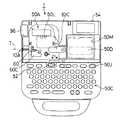
図1はテープライタ1の外観を本体カバー50Kを開いた状態で示す平面図、図2は本体カバー50Kを閉じた状態でのテープライタ1の右側面図、図3はこのテープライタ1に装着されるテープカートリッジ10の組立状態を示す平面図である。本実施例では、インクリボンとこのインクリボンを用いて印字されるテープとを同一のカートリッジに収納しているので、インクリボンカートリッジでもあるこのカートリッジを、以下、テープカートリッジと呼ぶ。
【0031】
テープライタ1は、図示するように、各種部品を収納する本体ケース50H、61個の入力用キーを備えた入力部50C、開閉自在な本体カバー50K、本体カバー50Kの下に視認可能に設けられ文字列やその他の情報を表示する表示部50D、本体カバー50Kを開いた本体左上部に設けられたテープカートリッジ10が着脱自在に装着されるカートリッジ装着部50Aおよび電源スイッチ50Jを備える。本体カバー50Kには、図1に二点鎖線で仮想的に示したように、テープカートリッジ10の装着を確認する窓50Lと表示部50Dを直視可能な窓50Mとが設けられている。なお、両窓50L,50Mには、透明なプラスチックの板材がはめ込まれている。また、本体カバー50Kの開閉は、図1には示されていない開閉検出スイッチ55にて監視される。
【0032】
このテープライタ1を使用する場合には、まず、本体カバー50Kを開き、ヘッド移動レバー63Cを、図1反時計周りに90度回し、カートリッジ装着部50Aにテープカートリッジ10を装着する。ヘッド移動レバー63Cを回した状態では、後述する印字ヘッド60は、ヘッドケース60C内に退避するので、テープカートリッジ10をカートリッジ装着部50Aに容易に装着することができる。その後、ヘッド移動レバー63Cを時計回りに回して図示の位置に戻す。この状態では、印字ヘッド60は印字可能位置まで移動しているが、ヘッド移動レバー63Cがテープカートリッジ10を抑える関係となるので、テープカートリッジ10を取り出そうとして、印字ヘッド60やテープカートリッジ10を痛めることがない。テープカートリッジ10を装着した後、本体カバー50Kを閉じる。なお、ヘッド移動レバー63Cを回した状態、即ち印字ヘッド60がヘッドケース60C内に退避した状態では、ヘッド移動レバー63Cが邪魔をして、本体カバー50Kを閉めることができず、印字動作そのものができない。
【0033】
本体カバー50Kを閉めた後、電源スイッチ50Jを操作して電源を投入し、入力部50Cから印字しようとする文字を入力する。入力した文字列を必要に応じて仮名漢字変換などし、所定のキーを操作して印刷を指示すると、テープカートリッジ10にて供給されるテープTに、後述する熱転写方式のプリンタ部50Bにより印字が行なわれる。印字されたテープTは、テープライタ1の左側面に設けられたテープ排出口10Aから排出される。本実施例で用いたテープTは、印字面が熱転写によるインクの載りを良好にするために加工されたものであり、粘着性を備えた裏面には剥離可能な剥離テープが張り合わされている。従って、印字されたテープを、内蔵のカッターにより切断し、裏面の剥離テープを剥がせば、文字や記号の印刷されたテープTを好きな場所に貼付することができる。
【0034】
図示してはいないが、テープライタ1の裏面には電池収納部が設けられており、装置全体の電源となる6個の単三電池が装着可能となっている。また、電源は、図示しないACアダプターを本体右側部に設けられたプラグ50へ接続することでも供給することが可能である。
【0035】
次に、図3,図4を中心に、テープカートリッジ10の構造と機能について説明する。なお、図5はそのA−A断面図である。このテープカートリッジ10は、同様の組立構成により、厚さ,幅,材質の異なるテープTを収納可能となっている。実施例では、収納しているテープTの形状および材質の種類として、テープ厚が100μm,200μmの2種類、テープ幅が6mm,9mm,12mm,18mm,24mmの5種類、テープ材質が印字面がポリエステルで裏面の剥離テープが紙(以下、「ポリエステル(紙)」のように記載する。),ポリエステル(ポリエステル),塩化ビニル(紙),紙(紙)の4種類の計40種類のテープカートリッジ10を提供している。また、印字面の材質がポリエステルまたは塩化ビニルのテープ(以下、「プラスチックテープ」という。)は、その印字面の色が透明,白,黄,水色の4種類、印字面の材質が紙のテープ(以下、「紙テープ」という。)は、透明を除く3種類が提供されている。さらに、テープカートリッジ10にテープTと共に収納されるインクリボンRは、その色が黒,赤,青,緑の4種類が提供されている。したがって、テープカートリッジ10の種類は、テープの厚さ,幅,色およびインクリボンRの色により、3種類のプラスチックテープが各160種類(2×5×4×4)、紙テープが120種類(2×5×1×3×4)の計600種類(3×160+120)となる。次表1にテープカートリッジ10の種類の一覧を示す。
【0036】
【表1】
印字に際して用いられるプラテン12は中空円筒状の部材であり、厚さ,幅,材質の異なるそれぞれのテープTおよびインクリボンRと印字ヘッド60との接触状態を良好なものとして良質な印字を可能とするため、その外周面にはテープTの種類に応じたプラテンゴム14が装着されている。このプラテンゴム14は、シリコンゴムにより形成されている。本実施例では、テープ厚に対応してプラテンゴム厚が1.9mm,2.0mmの2種類、テープ幅に対応してプラテンゴム幅がテープ幅6mm,9mm,12mm用および18mm,24mm用として12mm,18mmの2種類、テープTの硬さ,厚さ,幅に対応してプラテンゴム硬さがプラテンゴム幅12mm用として60度,65度,70度の3種類とプラテンゴム幅18mm用として40度,45度,50度,55度,60度の5種類、さらに剥離テープの材質に対応してプラテンゴム14の表面の粗さが粗いもの(300μm)と滑らかなもの(500μm)との2種類の計32種類のプラテンゴム14が用いられている。ここで、プラテンゴム硬さを表わす単位として用いた「度」は、JIS−K6301のゴム硬度計により用いられるゴムの硬度を表わす単位で、数値が大きくなるに従って硬くなる。プラテンゴム14の硬さの調整は、実際の印字テスト結果に基づいて行なう。実際の印字品位や印字強度が良好な範囲をもとめ、その場合の硬度を最適硬度とするのである。また、プラテンゴム表面の粗さは、μmを単位として示す。次表2に、実施例の各テープカートリッジに装着されるプラテンゴム14の種類の一覧を示す。
【0038】
【表2】
図6および図7にテープ幅に応じてプラテンゴム幅を変更したテープカートリッジの一例を示す。図6は、厚さが100μm,幅が6mmの紙テープを収納したテープカートリッジ10aを、インクリボンコア22,リボン巻取コア24およびプラテン12の中心を通る位置で破断して示す断面図である。図7は、同様に、厚さが100μm,幅が24mmの紙テープを収納したテープカートリッジ10bを示す断面図である。なお、図面を簡略化するため、図7における各部材の符号の表示は省略した。また、図6,図7において、テープライタ1への取り付け状態を説明するため、テープカートリッジ断面図に印字ヘッド60の一部を描いている。図示するように、プラテンゴム14をテープ幅に応じた幅とすることによりテープTが良好に搬送される。
【0040】
テープ厚に対応してプラテンゴム厚を変えるのは、プラテン12とテープガイドピン26とで、テープTをその厚さに関わらず確実に搬送すると共に、プラテン12と印字ヘッド60とで押圧して挟持するテープTおよびインクリボンRの押圧状態を一定にするためである。図8は、プラテン12と印字ヘッド60とでテープTおよびインクリボンRを挟持している様子を拡大して示した拡大説明図である。図中の実線は、テープ厚が100μmのときのプラテンゴム14AとテープTとを表わし、破線は、テープ厚が200μmのときのプラテンゴム14BとテープTとを表わす。図示するように、テープTの厚さに応じた厚さのプラテンゴム14を装着したことにより、プラテン12とテープガイドピン26は、テープTの厚さに応じた間隔となり、テープTを無理なく確実に搬送する。また、プラテン12と印字ヘッド60もテープTの厚さに応じた間隔となり、テープTおよびインクリボンRを、印字の実行について良好な押圧状態とする。したがって、テープTの厚さを問わず良好に印字することができる。
【0041】
テープTの硬さ,厚さ,幅に対応してプラテンゴム14の硬さを変えた一例を次表3に示す。表3に示したテープTは、テープ硬さの柔らかいものとして材質がポリエステル(ポリエステル)と紙(紙)の2種類,厚さが100μmと200μmの2種類,幅が9mmと18mmと24mmの3種類で計12種類、テープ硬さの硬いものとして紙(紙)とポリエステル(紙)と塩化ビニル(紙)の3種類,厚さが紙(紙)の100μmとポリエステル(紙)および塩化ビニル(紙)の200μmの3種類,幅が9mmと18mmと24mmの3種類の計9種類である。また、表3に示したプラテンゴム14の硬さの欄には、そのテープTに対して最も良好に印字することができる値を中央値として示すと共に、良好な印字が可能な範囲を示した。
【0042】
【表3】
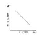
表3に示すように、テープTに良好に印字することができるプラテンゴム14は、テープTの硬さと厚さが同じときにはテープ幅が広いほど、テープTの硬さと幅が同じときにはテープ厚が厚いほど、テープTの厚さと幅が同じときにはテープ硬さが硬いほど柔らかなものとなっている。テープTの幅が広いほどプラテンゴム14を柔らかくするのは、テープライタ1に装着した際の印字ヘッド60による押圧力が印字ヘッド60をプラテン側に押しつけるばねによって定まりテープTの幅によらず一定なので、テープTの幅を広くすると、印字ヘッド60による単位面積当たりの押圧力が小さくなって印字ヘッド60とテープTとの接触状態が良好な状態からずれてしまい、良好な印字が得られなくなるからである。従って、プラテンゴム14を柔らかくして印字ヘッド60とテープTとを良好な接触状態としている。テープTが厚いほど、あるいは硬いほどプラテンゴム14を柔らかくするのも、テープ幅の場合と同様に、印字ヘッド60とテープTとの接触状態を良好な状態とするためである。図9,図10および図11に、テープTの硬さ,厚さ,幅と良好な印字が可能なプラテンゴム14の硬さとの関係の一例を表わすそれぞれのグラフを示す。こうしたテープTの硬さ,厚さ,幅と良好な印字が可能なプラテンゴム14の硬さとの関係を4元マップとすれば、任意の性状のテープTに適応する硬さのプラテンゴム14を求めることができる。
【0044】
また、実施例では、プラテンゴム14の表面の粗さを、テープTの剥離テープが紙のときには、滑らか(500μm)にし、剥離テープがポリエステルのときには、粗く(300μm)している。剥離テープがポリエステルのときにプラテンゴム14の表面を粗くするのは次の理由による。プラテンゴム14はシリコンゴムにより形成されているから、プラテンゴム14の表面を滑らかにしておくと、テープライタ1にテープカートリッジ10を長時間装着したときにプラテンゴム14と剥離テープとが軽く固着する場合が生じる。この固着した状態で印字を行なうと、テープTがテープ排出口10Aから良好に排出されず、テープカートリッジ10内で詰まってしまう場合が生じる。このため、プラテンゴム14と剥離テープとが固着しないよう、または固着しても剥離しやすいようプラテンゴム14の表面を粗くするのである。したがって、プラテンゴム14の表面の粗さは、テープTの剥離テープの材質および剥離テープ表面の粗さによって定まるものである。
【0045】
図12は、外径が9mmで幅が12mmのプラテンゴム14を軸に沿った面で切断した断面を示す断面図である。図示するように、プラテンゴム14は、中央部14bの外径が9.2mmで、両端部14aの外径が9.0mmの樽形をしている。このように樽形としたのは、両端部14aの外径を中央部14bの外径より大きくすると、テープTまたはインクリボンRが、プラテンゴム14の中央部14bを中心として安定して搬送されず、一方の端部14aによってしまう場合が生じるからである。したがって、中央部14bの外径が両端部14aの外径以上であれば、こうした不都合は回避することができる。しかし、中央部14bの外径を両端部14aの外径と等しいプラテンゴム14を形成すると、製造精度を高くしても製品に多少のバラツキが生じることから、僅かではあるが中央部14bの外径が両端部14aの外径より小さなプラテンゴム14が生じてしまう。このプラテンゴム14は、程度の差はあるが上記の不都合を生じる。実施例でプラテンゴム14を樽形とするのは、こうした製品のバラツキにより生じる不都合を回避するためである。実施例では、プラテンゴム14を中央部14bの外径を両端部14aの外径より0.2mm大きくしたが、中央部14bの外径を両端部14aの外径より1%ないし3%大きくする構成が望ましい。中央部14bの外径を両端部14aの外径より3%を越えて大きくしないのは、3%を越えて大きくすると、両端部14a付近でのテープTの印字ヘッド60への押圧が不足して印字がかすれる等の印字不良を生じるからである。なお、幅が18mmのプラテンゴム14も同様な樽形をしている。
【0046】
こうしたプラテンゴム14を装着したプラテン12の上下両端部外周は、プラテン12の軸径に対して僅かに小径に形成され、この小径部分をテープカートリッジ10の天壁16および底壁18に形成された嵌合孔16A、18Aに回動可能に遊嵌することで、プラテン12は回動自在とされている。なお、この嵌合孔16A,18Aは、図3,図4に示すように、略長円形状をなしている。この様にしてテープカートリッジ10に立設されるプラテン12は、テープライタ1に設けられた後述するプラテン駆動軸に対して着脱自在であり、かつプラテン駆動軸に係合した状態では同駆動軸から回転駆動力が伝達可能でなければならない。このため、プラテン12の中空部内周面には、図4および図6に示すように、回転軸方向に6つの係合条12Aが等間隔に形成されている。
【0047】
テープカートリッジ10にはその他に、長尺状のテープTおよびインクリボンRをコンパクトに巻取り収納するためにテープコア20、インクリボンコア22およびリボン巻取コア24が立設されている。また、テープカートリッジ10には、後述する印字ヘッドが侵入する進入孔32が設けられている。この進入孔32の外周には、ガイド壁34が形成されている。
【0048】
テープコア20は大径の中空円筒状のリールで、長いテープTを肉薄に巻取収納できるように配慮される。従って、最外周に位置するテープT(図3中の符号イ)を引き出す際のテープコア20の回転角速度と最内周に位置するテープT(図3中の符号ロ)を同速度で引き出す際のテープコア20の回転角速度とはあまり相違しない構成となっている。また、巻取収納の際の曲率が小さく曲げ応力に弱い材質のテープTを用いたとしても、無理なく収納することができる。
【0049】
図5に示すように、テープコア20には、その中心に軸孔20Bが形成され、テープカートリッジ10の底壁18から立設された軸体18Bに回転自由に嵌め込まれている。テープコア20の軸方向上下端には、円形の薄いフィルム20Aが貼付されており、そのテープT側の面は接着剤層となっている。このフィルム20Aは、テープTに対してフランジ部として働くが、テープT側の面に接着剤層が設けられていることから、テープTの小口はこのフィルム20Aに軽く付着する。従って、プラテン12の回転によりテープTが引き出され、テープコア20が従動回転しても、テープTがばらけることはない。
【0050】
テープコア20に巻取収納されるテープTは、テープカートリッジ10の底壁18から立設されたテープガイドピン26を経由してプラテン12へ至り、テープカートリッジ10のテープ排出口10Aから外部に引き出されている。テープ排出口10Aの部分は、テープTの搬送方向に沿って、所定の長さにガイド部10Bが形成されている。テープカートリッジ10をカートリッジ装着部50Aに装着した状態では、進入孔32に印字ヘッド60が位置する。この状態で、印字ヘッド60とプラテン12とによりテープTは挟持され、プラテン12の回転により、テープTは搬送されるのである。この際、プラテン12に装着されたプラテンゴム14の厚さがテープTの厚さに対応しているので、テープTは、その厚さに関わらずインクリボンRを介して印字ヘッド60と同じ接触状態となる。
【0051】
プラテン12の上下の端部が嵌め込まれた嵌合孔16A,18Aは、既述したように、長円形状をしているので、テープカートリッジ10単体の状態では、プラテン12は、嵌合孔16A,18Aの長軸に沿って移動可能である。従って、テープカートリッジ10の外からテープTをテープカートリッジ10内部に押し込もうとすると、このテープTの動きによりプラテン12は、テープTの搬送路に沿って移動する。プラテン12が移動するとプラテン12のプラテンゴム14はテープガイドピン26の外周に当接し、テープガイドピン26との間でテープTを挟持する。この結果、テープTはそれ以上移動不能となり、テープTがテープカートリッジ10の内部に押し込まれることはない。
【0052】
インクリボンコア22は、図6,図7に示すように、小径の中空円筒状部材により構成されるが、その上下両端部の外周は僅かに小径に形成されている。この小径とされた下端部分の端面には、図3,図4に示すように、等間隔に6箇所の溝がその軸方向に形成され、係合部22Aをなしている。この下端側の小径部分は、テープカートリッジ10の底壁18に形成された円形の嵌合孔部18Cに遊嵌されている。また、インクリボンコア22の上端中空部分は、テープカートリッジ10の天壁16に突設された円筒状のガイド突部16Cに遊嵌されている。従って、この状態では、インクリボンコア22は、インクリボンRの引き出しに連れて従動回転自在に保持される。なお、テープカートリッジ10の天壁16を構成する蓋体とインクリボンコア22との間には、図13に示すように、円環座金23が介装されており、円環座金23の変形によってインクリボンコア22を底壁18方向に押圧することにより、インクリボンコア22の自由な回転を規制している。
【0053】
また、図3,図4に示すように、テープカートリッジ10の底壁18であって、インクリボンコア22と後述するリボン巻取コア24との底部近傍には、細い略L字状の係合片18Dが形成されている。係合片18Dは、テープカートリッジ10の底壁18の一部分(図3中のハッチ部分X)をくり抜くことで、形成されている。従ってこの係合片18Dの先端部は、底壁18を構成している部材の弾性により底壁18に連続している基端部18Eを支点として、底壁18の平面方向に沿って移動自在となる。この係合片18Dに何等の力が作用していない状態にあっては、その移動自在の端部は嵌合孔部18Cの外周内側に位置するため、前述のごとく嵌合孔部18Cに遊嵌されたインクリボンコア22の端部に形成された6個の係合部22Aの何れかと係合し、インクリボンコア22の回転を阻止する。
【0054】
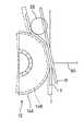
インクリボンコア22に巻取収納して供給されるインクリボンRは、リボンガイドローラ30にガイドされて前述したテープTと重合状態となってプラテン12にまで至り、更に印字ヘッドが進入する進入孔32の周面に形成されたガイド壁34を介してリボン巻取コア24に至る。テープカートリッジ10が未使用状態にあるとき、すなわちインクリボンRの始端のみがリボン巻取コア24に着設されている時のインクリボンRの引き回し状態を図3中の符号ハに、またインクリボンRの総てがリボン巻取コア24に巻取られたときの同状態を符号ニに示している。
【0055】
リボン巻取コア24は、図示するごとくインクリボンコア22と略同型の中空円筒状部材により構成される。そして、その上下両端部の外周もインクリボンコア22と同様に、僅かに小径に形成されている。その小径とされた下端部端面には、等間隔毎に6個の係合部24Aが凹設される。一方、このリボン巻取コア24は、プラテン12同様にテープライタ1に設けられる後述するリボン巻取コア駆動軸に係合して回転駆動可能とするため、その中空部内周面には軸方向に6つの係合条24Bが等間隔に形成されている。この様に構成されるリボン巻取コア24は、上下端に形成された小径部分をテープカートリッジ10の底壁18および天壁16に形成された円形の嵌合孔部16G、18Gに遊嵌され回動自在に立設される。
【0056】
また、リボン巻取コア24の不測の回転を防止するため、テープカートリッジ10の底壁18には、前述と同じく嵌合孔部18Gの外周内側にその端部を位置する細い略L字状の係合片18Hが形成されている。即ち、テープカートリッジ10の底壁18の一部分(図3中のハッチ部分Y)がくり抜かれて、係合片18Hとされている。テープカートリッジ10が単体の状態では、この係合片18Hの端部が、リボン巻取コア24の端部に形成された6個の係合部24Aの何れかと係合しており、リボン巻取コア24の回転は阻止されている。なお、係合片18D,18Hの先端が係合部22A,24Aに対して直角ではなく、斜めに対峙していることから、インクリボンコア22およびリボン巻取コア24は、反時計回り回転することは可能である。
【0057】
この様なインクリボンコア22の係合部22Aと係合片18Dとの係合およびリボン巻取コア24の係合部24Aと係合片18Hとの係合は、共に、テープカートリッジ10をカートリッジ装着部50Aに装着することにより解除されるが、その構成は、カートリッジ装着部50Aの構造と合わせて、後述する。
【0058】
この様なリボン巻取コア24に巻取られるインクリボンRは、熱転写型のリボンであり、その幅は印字される側のテープTの幅に応じて複数種類用意される。本実施例では、図6に示したように、テープ幅6,9,12mm用として12mm幅のインクリボンと、図示しないがテープ幅18mm用として18mm幅のインクリボンと、図7に示したように、テープ幅24mm用として同幅の24mm幅のインクリボンと、計3種類のインクリボンRを用意している。
【0059】
インクリボンRは、リボン幅がテープカートリッジ10の高さと等しいものの場合には(図7参照)、インクリボンRは天壁16およぴ底壁18にガイドされるので、リボン巻取コア24の外周にはフランジ部は形成されていないが、リボン幅が狭いテープカートリッジ10の場合には、インクリボンRを安定してプラテン12に供給できるように、リボン巻取コア24の外周には、巻取収納しているインクリボンRの幅に適合したフランジ部24Cが形成され、このフランジ部24CにてインクリボンRを案内している(図6参照)。
【0060】
本実施例では、この3種類の幅の異なるインクリボンRに対応した硬さのプラテンゴム14を用いている。インクリボンRの幅に対応した硬さのプラテンゴム14の一例を表4に示す。表4には、インクリボンRの幅とプラテンゴム14の硬さとの関係が理解しやすいよう、テープTの厚さ,幅,材質を一定とした。すなわち、テープTは、厚さが100μmで幅が18mmの紙テープ(紙(紙))と、厚さが200μmで幅が18mmのプラスチックテープ(ポリエステル(紙))とを用い、このテープTに対してインクリボンRの幅を12mm,18mm,24mmとしたときに良好な印字が可能なプラテンゴム14の硬さを中央値と範囲として示した。
【0061】
【表4】
表4に示すように、インクリボンRの幅が広くなるほどプラテンゴム14を柔らかくなっている。これは、次の理由による。インクリボンRは、印字ヘッド60により印字が可能な状態を表わした図14に示すように、円環座金23により回転を規制されたインクリボンコア22からリボンガイドローラ30にガイドされてテープTと共にプラテン12と印字ヘッド60とで挟持され、さらにヘッドケース60Cの周面に形成されたガイド壁34を介してリボン巻取コア24に至る。このインクリボンRで良好な印字を得るためには、一定の張り、即ち長さ方向に単位幅当たり所定の範囲の張力(例えば、1.1gf/mmないし1.7gf/mm)を必要とする。この張力は、湾曲した薄板状の円環座金23がインクリボンコア22と天壁16とに押圧されることによりインクリボンコア22の回転に対して逆方向に作用する摩擦力を生じさせるにより得られ、その大きさは、円環座金23の湾曲の程度や円環座金23の厚さにより調節がなされる。インクリボンRは、単位幅当たり所定の張力が必要なので、インクリボンRの幅が広くなれば、張力は大きくなる。
【0063】
印字ヘッド60により印字が可能な状態では、印字ヘッド60は、図中破線で示したインクリボンRをプラテン12の位置まで押し上げる。この際、印字ヘッド60は、インクリボンRの張力によるプラテン12を押圧する方向と反対方向(図中矢印方向)の力が作用するので、その力の分だけプラテン12への押圧力が小さくなる。インクリボンRは、上述したように、単位幅当たりの張力が所定の範囲になるよう円環座金23が調節されているから、インクリボンRの幅が広くなるほど印字ヘッド60のプラテン12への押圧力が小さくなる。したがって、幅の異なるインクリボンRに同じ硬さのプラテンゴム14を用いると、インクリボンRの幅が広くなるほど印字ヘッド60のプラテン12への押圧力が小さくなるから、インクリボンRの幅が広くなるほどプラテンゴム14の変形量が小さくなる。この結果、印字ヘッド60とプラテン12との釣り合いの位置が印字ヘッド60側へ変化し、プラテン12によるテープTの単位時間当たりの搬送量が多くなり、良好な印字ができなくなる。
【0064】
したがって、インクリボンRの幅が広くなるほど柔らかいプラテンゴム14を用いることにより、インクリボンRの幅が広くなるほど小さくなる印字ヘッド60のプラテン12への押圧力に対して、プラテンゴム14の変形量をインクリボンRの幅に関わらず一定とし、印字ヘッド60とプラテン12との釣り合いの位置を同じ位置とする。この結果、テープTの搬送量が均一となり、良好な印字が可能となる。
【0065】
本実施例のテープカートリッジ10は、上述のごとく、収納したテープTの厚さ,幅,材質およびインクリボンRの色によりすべての組み合わせを数えれば600種類が存在する。テープTの幅が異なると、印字できる領域等も異なるから、テープカートリッジ10の幅の種類を検出する必要が生じる。実施例のテープカートリッジ10では、図3に示したように、カートリッジの底壁18に3つの検出孔18Ka,18Kb,18Kcを設け、テープカートリッジ10の種類を判別可能としている。即ち、この検出孔18Ka,18Kb,18Kcを、巻取収納しているテープTの幅に応じて、異なる深さに形成しているのである。従って、この検出孔18Kの深さを検出するセンサを設ければ、最大7種類のテープ幅のテープカートリッジ10を判別することができる。
【0066】
以上詳細に説明したテープカートリッジ10は、テープライタ1のカートリッジ装着部50Aに装着される。以下、テープライタ1の機械的な構成部の各々について、順次説明する。図15は、カートリッジ装着部50A近辺の概略構成を示す斜視図であり、印字したテープTを切断するカッターボタン96を破線で表した斜視図である。また、図16は、ステッピングモータ80の動力によりプラテン12などを駆動する駆動機構50Pの要部構成を実線で、ヘッド移動レバー63Cの回動操作によりヘッド回転軸64を中心として回転する回転フレーム62を点線で示す斜視図である。
【0067】
カートリッジ装着部50Aは、入力部50Cの後側、かつ表示部50Dの左側、すなわちテープライタ1本体の左後方に配置され、図15に示すように、前述したテープカートリッジ10の形状に合致した装着空間として形成されている。この装着空間には、リボン巻取コア24およびプラテン12の各中空部分に係合する軸および印字ヘッド60が立設されている。また、カートリッジ装着部50Aの下部にはベースボード61がねじにより取り付けてあり、このベースボード61には、図16に示すようにステッピングモータ80の回転をプラテン12等に伝達する駆動機構50Pおよび図15に示すようにテープカッター90などが設けられている。しかし、通常の状態ではこのベースボード61は、カートリッジ装着部50Aのケースに仕切られており、本体カバー50Kを開いただけでは、駆動機構50Pなどを直接視認することはできない。図16は、このケースを外し、その駆動機構50Pを描画した説明図である。また、図16には、ヘッド移動レバー63Cの操作に応じてヘッド本体65を印字位置あるいは退避位置へ移動する回転フレーム62およびカム部材63Aを点線により示している。
【0068】
このカートリッジ装着部50Aへのテープカートリッジ10の装着あるいは交換は、本体カバー50Kを開けて行なわれる。カートリッジ装着部50Aの手前に設けられるスライドボタン52(図1参照)を右にスライドさせると本体カバー50Kと本体との係合が解除され、本体カバー50Kが本体後部のカバーヒンジ54を支点として回転し、これを開けることができる。
【0069】
カートリッジ装着部50Aに装着されるテープカートリッジ10の底壁18には、インクリボンコア22およびリボン巻取コア24の回り止めのためにこれに係合する係合片18D,18Hが設けられていることは既述した。係合片18D,18Hは、底壁18の一部(図3ハッチ部XおよびY)をくり抜くことで形成されており、このハッチ部X,ハッチ部分Yの中ほどの位置に対応するカートリッジ装着部50Aの部位には、図15に示すように、くさび形の2つの当接突起70A、70Bが立設されている。従って、テープカートリッジ10をカートリッジ装着部50Aに装着すると、この当接突起70A,70Bがハッチ部分X,ハッチ部分Yに嵌まり、係合片18D,18Hをインクリボンコア22およびリボン巻取コア24の端部から遠ざける方向に押し分ける。これにより、係合片18D,18Hによる係合は解除され、インクリボンコア22およびリボン巻取コア24は回転可能な状態となる。
【0070】
次に、ステッピングモータ80の回転をプラテン12のプラテン駆動軸72等に伝達する伝達機構について説明する。図16に示したように、ステッピングモータ80の回転軸80Aには、第1のギヤ81が取り付けられており、更に、クラッチアーム80Bが回転軸80Aに所定の摩擦を持って嵌合されている。このクラッチアーム80Bには、第1のギヤ81と噛合する第2のギヤ82およびこの第2のギヤ82と同心一体に形成された第3のギヤ83(図16では、第2のギヤ82の下方に隠れているため、点線により示している)とが取り付けられており、第3のギヤ83と噛合する最大径の第4のギヤ84と共に、ワンウェイクラッチを構成している。即ち、ステッピングモータ80が図示矢印C方向に回転すると、回転軸80Aとクラッチアーム80Bとの摩擦により、クラッチアーム80Bは、第2および第3のギヤ82,83と共に矢印C方向に回転し、第4のギヤ84に係合する。この結果、ステッピングモータ80の回転は第4のギヤ84まで伝達される。ワンウェイクラッチの働きについては、後述する。
【0071】
第4のギヤ84の回転により、この第4のギヤ84と同心一体に形成された第5のギヤ85が同一方向に回転し、その回転力は第6のギヤ86および第7のギヤ87に伝達される。第6のギヤ86は、その回転軸が巻取コア駆動軸74に結合されており、ステッピングモータ80の回転によりインクリボンRを巻き取ってゆく。尚、実際にリボン巻取コア24を駆動するリム74Aは、巻取コア駆動軸74に対して所定の摩擦を持って取り付けられており、通常の状態では、ステッピングモータ80による巻取コア駆動軸74の回転に従って回転するが、リボン巻取コア24がインクリボンRの終端に至った等の理由で回転不能となった場合には、巻取コア駆動軸74の回転に対してスリップするものとされている。
【0072】
第7のギヤ87の回転は、同心一体に形成された第8のギヤ88と噛合する第9のギヤ89に伝達され、プラテン駆動軸72を回転する。プラテン駆動軸72の下部には、プラテン12の内周面の凹凸と嵌合してこれを駆動するリム72Aが設けられている。従って、ステッピングモータ80が回転し、ワンウェイクラッチによりその回転が第4のギヤ84に伝達されると、最終的には、プラテン駆動軸72と巻取コア駆動軸74とが回転し、プラテン12の外周に設けられたプラテンゴム14と印字ヘッド60のヘッド本体65との間に挟持されてたテープTを、印字に合わせて搬送すると共に、このテープTの搬送に同期してインクリボンRを巻き取ってゆく。
【0073】
プラテン駆動軸72および巻取コア駆動軸74の軸外周には、プラテン12やリボン巻取コア24の中空内周面に形成されている係合条と係合する突条72B,74Bが等間隔に3つ形成されている。このプラテン駆動軸72および巻取コア駆動軸74をステッピングモータ80により所定回転速度で回転駆動すれば、テープTおよびインクリボンRをテープコア20およびインクリボンコア22から所定量ずつ引き出して互いに重合状態とし、プラテンゴム14と印字ヘッド60との間を通過させる。この時、印字ヘッド60に通電してドット単位での発熱量を制御すれば、インクリボンRのインクをテープTに熱転写し、テープTへ印字することができる。印字の後、テープカートリッジ10からは印字の完了したテープTのみが排出され、印字に使用されたインクリボンRはリボン巻取コア24に巻取回収される。
【0074】
このように印字と共にテープTが搬送されると、テープTは、本体左側面のテープ排出口10Aから送り出されてくる。このテープTは、後述する切断機構により切断するのが本来であるが、使用者によっては、テープTを切断前に引き出そうとすることがある。しかし、このテープTへの印字が可能な状態、すなわち印字ヘッド60がプラテン12のプラテンゴム14にテープTを押圧している状態にあっては、テープTを無理に引き出そうとすると、プラテン駆動軸72も回転しようとする。このプラテン駆動軸72は、大きくギヤダウンしていることとステッピングモータ80の保持トルクがある程度あることから、通常の駆動機構ではこのプラテン駆動軸72を回転することはできない。また、当然巻取コア駆動軸74も回転しない。従って、テープTを引き出すと、テープTと共にインクリボンRが引き出されてしまう。この状態で切断機構を使用してテープTを切断するとインクリボンRも切断してしまうから、こうした事態は起きてはならない。
【0075】
本実施例では、記述したクラッチアーム80Bと第2ないし第4のギヤ82〜84とにより構成されたワンウェイクラッチにより、この問題を回避している。即ち、テープTを引き出そうとすると、プラテン12と共にプラテン駆動軸72が回転する。このプラテン駆動軸72の回転は、ギヤトレインを介して第4のギヤ84まで伝達され、これを反時計回りに回転する。この時、第3のギヤ83を回転しようとするが、ステッピングモータ80の回転軸80Aが回転しないため、第4のギヤ84の回転力は第3のギヤ83を軸支するクラッチアーム80Bを押し退け、第3のギヤ83と第4のギヤ84との係合を解消する。この結果、第4のギヤ84から第9のギヤ89までは、ステッピングモータ80から切り放された形となり、テープTの引き出しに伴うプラテン駆動軸72の回転により、巻取コア駆動軸74も回転することになる。従って、テープTの引き出しに伴ってインクリボンRも巻き取られることになり、テープTと共に外部に引き出されてしまうということがない。なお、ステッピングモータ80が回転すれば、その回転によりクラッチアーム80Bは、再び第4のギヤ84側に移動し、第3のギヤ83と第4のギヤ84とは係合する。こうしたクラッチアーム80Bの動きは、ベース61に設けられ、クラッチアーム80Bの先端が嵌められた開口80Cにより、一応規制されている。
【0076】
上記印字動作によりテープカートリッジ10から左方へと排出される印字済みのテープTは、図15に示されている切断機構を用い、次のよう簡単に切り取ることができる。カートリッジ装着部50Aの底部より突出されるカッター支持軸には回動自在の略「L」字状をしたテープカッター90および図示しないばねが嵌合されており、このばねの弾発力によってテープカッター90は図示する状態、すなわち図15において実線矢印Dにて表している反時計方向への回転力が加えられた状態で維持される。この回転力により、テープカッター90の図示上右側に位置する右端部90Aは、カッターボタン96をその裏面より押し上げている。テープカッター90の右端部90Aは、二股状に形成され、ここにカッターボタン96の裏面に設けられたピン96Aが挿入されている。従って、カッターボタン96を下方に押し込むと、テープカッター90の左端部90Bはこれに連れて、下方向に移動される。
【0077】
また、テープカッター90の左端部90Bには、テープTを切断するための移動刃98が形成されており、カートリッジ装着部50Aの側面に取り付けられた固定刃91に対して一定の角度で離隔している。従って、カッターボタン96を押し込むことによりテープカッター90がばね力に抗して図示時計方向へ回動し、その移動刃98と固定刃91とによりテープTを切断することができる。なお、このカッターボタン96の操作にリンクして図示しないテープ抑えが移動して、移動刃98と固定刃91によるテープTの切断に先だって、テープTを固定するように作用する。また、このテープ抑えの移動は、図示しない検出スイッチ99により検出され、その検出信号を利用することで、テープTの切断中には印字を行なわないように制御されている。
【0078】
次に、テープカートリッジ10のテープTに印字を行なう印字ヘッド60が、プラテン駆動軸72に近接した印字位置およびテープカートリッジ10をカートリッジ装着部50Aから着脱するためにプラテン駆動軸72から離隔した退避位置に移動する機構について説明する。印字ヘッド60は、図16および後で詳述する図17に示すように、ベースボード61から立設されたヘッド回転軸64に回転自在に軸支された回転フレーム62の立設部62Aに対し、放熱板65bを介してヘッド本体65を取り付て構成される。図16に点線で示す回転フレーム62は、図示しないばねにより点線の矢印Eで示す方向へ強く引き付けられており、カム部材63Aに当接して安定している。回転フレーム62がこの状態で安定している時、ヘッド回転軸64を中心として回転する回転フレーム62の立設部62Aは、プラテン駆動軸72に最も接近した状態となり、ここに取り付けられている印字ヘッド60はテープTに対して印字を実行することができる。
【0079】
カム部材63Aの回転軸63Aaは、図15に示すカートリッジ装着部50Aに立設された円筒部材50Aaを貫通しているレバー回転軸63Bの下端に接続され、このレバー回転軸63Bの上部にはヘッド移動レバー63Cが一体に設けられている。従って、ヘッド移動レバー63Cを図15に点線Fで示すように反時計方向に大きく90度回転すると、図16に示すカム部材63Aも同様に反時計方向に90度回転する(図16矢印G参照)。この回転により、カム部材63Aの凹部63Abと回転フレーム62の凸部62Bとが嵌合し、安定した状態となる。この時、回転フレーム62の立設部62Aは最もプラテン駆動軸72から離隔し、ここに取り付けられている印字ヘッド60は退避位置となってテープカートリッジ10の着脱が可能となるのである。
【0080】
上記のごとく印字位置および退避位置に回転移動される印字ヘッド60の詳細な分解斜視図を、図17に示している。この図は、印字ヘッド60を図15,図16とは、反対側から描いている。図示するように、印字ヘッド60は、ベースボード61から立設されたヘッド回転軸64に回転自在に軸支された回転フレーム62の立設部62Aに対し、放熱板65bを介してヘッド本体65を取り付て構成される。複数の発熱体HTを配列したヘッド本体65は、発熱量が大きいことから放熱板65bに着設されるのであり、また回転フレーム62に取り付けられて回転移動する必要からヘッド本体65への電気的な配線は可撓性に優れたフレキシブルケーブル68が用いられている。
【0081】
放熱板65bは、回転フレーム62の立設部62Aに対して2箇所で保持される。一箇所は、ヘッド回転軸64を利用した保持であり、放熱板65bに穿設された2つの角孔65baにヘッド回転軸64を貫通させている。この角孔65baは、テープの走行方向が短軸となるよう穿設されるもので、短軸の長さはヘッド回転軸64の直径に略等しく、長軸の長さはヘッド回転軸64の直径の2倍程に設計されている。もう1つの保持箇所は、ヘッド回転軸64に直角な方向に突設された回転フレーム62の回転軸受け62Aaと放熱板65bの回転軸受け65bbとを貫通して取り付けられるピン67bによりなされている。これにより放熱板65bは、テープ走行方向に対してはその角孔65baの短軸によって正確な位置決めがなされ、またテープTの幅方向に対してはその角孔65baの長軸およびピン67bを中心に回転自在とされる。この結果、印字ヘッド60をプラテン12側に押しだしたとき、ヘッド本体65は、プラテン12に対向する印字位置に正確に位置し、かつ、プラテン12との間に挟持されるテープTがその幅方向に傾いている場合にもピン67bを中心とした回転揺動により、発熱体HTが、テープTを均一にプラテン12に押圧することになる。この際、プラテン12に装着されたプラテンゴム14の厚さと硬さとがテープTの硬さ,厚さ,幅に対応しているので、テープTは、その硬さ,厚さ,幅に関わらず略一定の圧力で押圧される。
【0082】
次に、テープライタ1に組み込まれた入力部50C,表示部50D,プリンタ部50B等の詳細について説明するが、全体の理解の便を図って、先に制御回路部50Fを中心とする各部の電気的な構成について、その概略を説明する。本体カバー50Kの直下には、プリント基板に組み立てられた制御回路部50Fが、プリンタ部50B等と共に組み込まれている。全体の電気的な概略構成を、図18に示す。即ち、このテープライタ1の制御回路部50Fには、ROM,RAM,入出力ポートを一体に組み込んだ1チップマイクロコンピュータ(以下、CPUと呼ぶ)110およびマスクROM118の他、CPU110と入力部50C,表示部50D,プリンタ部50B等とのインタフェースを行なう各種回路が組み込まれている。CPU110は、インタフェース回路を介してあるいは直接に入力部50Cや表示部50D等に接続され、これらを制御する。
【0083】
入力部50Cは、図19に示すように、48個の文字入力キーおよび13個の機能キーの計61キーが備えられている。文字入力キーはJIS配列に基づいた、いわゆるフルキー構成であり、操作するキーの数の増加を抑えるために公知のシフトキーを備えるなど一般のワードプロセッサと同様である。機能キーとは、文字入力や編集、印刷など頻繁に使用される機能をワンタッチで実行可能にするためのもので、テープライタ1の機能性を高めている。
【0084】
これらの各キーは、8×8のマトリックスに割り当てられている。即ち、CPU110から見ると、図18に示すように、入力ポートPA1ないし8およびPC1ないし8の16ポートは、図示するごとくグループ化され、その各交点に入力部50Cの61種類のキーが配置されている。キーの詳細を図19に示した。電源スイッチ50Jは、このマトリックスキーとは独立に設けられ、CPU110のノンマスカブルインターラプトNMIに接続されている。CPU110は、電源スイッチ50Jが操作されると、マスクすることができない割込を起動し、電源の投入もしくは電源断の各処理を行なう。
【0085】
本体カバー50Kの開閉を検出する開閉検出スイッチ55からの検出出力はポートPB5に入力され、CPU110により本体カバー50Kの開閉状態が割り込みにより監視される。この開閉検出スイッチ55により、印字ヘッド60の駆動中に本体カバー50Kの開状態が検出された場合には、主表示部50Daに所定のエラー表示を行なうと共に、プリンタ部50Bへの電源供給をオフする。
【0086】
CPU110のポートPH,PM,PLは、ヘッドランク判別部112に接続さている。ヘッドランク判別部112とは、製造工程によるばらつきの大きい印字ヘッド60の抵抗値の測定結果からこれを幾つかのランクに分け、その測定結果に応じてヘッドランク判別部112の3つのジャンパー部112A,112B,112Cを設定するものである。従ってCPU110は、このヘッドランク判別部112の状態を読み取り、その入力結果に応じて印字ヘッド60の駆動時間、即ち発熱量を補正し、印字の濃さのバラツキを防止している。
【0087】
プリンタ部50Bによる印字は熱転写により行なわれるから、印字の濃さは、サーマルヘッドである印字ヘッド60の通電時間のみならず、外気温,駆動電圧によっても変動する。これらを検出するのが、温度検出回路60A,電圧検出回路60Bである。これらの回路60A,60Bは、印字ヘッド60に一体に組み込まれており、その出力は、CPU110の2チャンネルのアナログ−ディジタル変換入力ポートAD1,AD2に接続されている。CPU110は、このポートAD1,2の電圧をディジタル信号に変換して読み取ることにより、印字ヘッド60の通電時間を補正している。
【0088】
CPU110のポートPB1ないし3には、判別スイッチ102が接続されている。判別スイッチ102は、図15に図示するように、カートリッジ装着部50A右下隅に設けられている。この判別スイッチ102は、テープカートリッジ10に穿設された3つの検出孔18Kにそれぞれ入り込む3つのカートリッジ判別スイッチ102A,102B,102Cを一体形成したものである。このカートリッジ判別スイッチ102A,102B,102Cの突出長は、前述したテープカートリッジ10に穿設される検出孔18Kの深さに合わせて設計されており、浅い検出孔18Kに入り込んだカートリッジ判別スイッチ102はその検出孔18Kに当接して押圧され、スイッチがオン状態となる。また、深く穿設された検出孔18Kに入り込んだカートリッジ判別スイッチ102は、検出孔18Kにそのまま緩やかに嵌合し、スイッチはオフ状態となる。従って、この判別スイッチ102の3つのカートリッジ判別スイッチ102A,102B,102Cの状態を検出することで、現在カートリッジ装着部50Aに装着されているテープカートリッジ10の種類、すなわちテープカートリッジ10に収納されているテープTの幅を判別することができる。テープTの幅の情報は、印字する文字の大きさの制御等の他、後述するプリンタ部50Bの制御にも用いられている。
【0089】
CPU110のポートPB7には、プラグ50Nの接点からの信号が入力されている。プラグ50Nは、ACアダプタ113からの直流電源をジャック115が差し込まれることにより受け入れるが、この時、ブレイク接点の働きによりバッテリBTから電源部114への電源供給は遮断され、バッテリBTの電力消費は回避される構成となっている。同時に、プラグ50Nに設けられたいま一つの接点の信号は、CPU110のポートPB7に入力される。従って、CPU110は、この信号を判別することにより、テープライタ1の主電源がACアダプタ113によるものかバッテリBTによるものかを判断して、異なる制御を行なうことが可能である。本実施例では、ACアダプタ113から電源供給を受けている場合には、プリンタ部50Bによる印字速度を最大としており、一方バッテリBTから電源供給を受けている場合には、プリンタ部50Bによる印字速度を低下させ、印字ヘッド60に通電する電流のピークを抑え、バッテリBTの電力消費を低減している。
【0090】
CPU110のアドレスバス,データバスに接続されるマスクROM118は、明朝体で16×16、24×24、32×32の3種類の書体の仮名、漢字、特殊文字のセットを記憶する8メガビットのマスクROMである。その24ビットのアドレスバスAD、8ビットのデータバスDA、チップセレクト信号CS、出力イネーブル信号OEは、CPU110のポートPD0ないしPD33に接続されている。これらの信号は、そのまま外部入出力コネクタ50Eaにも接続されているから、外部入出力コネクタ50Eaに装着された拡張部50Eも、マスクROM118と同様アクセスすることができる。
【0091】
制御回路部50Fに直接接続可能に設けられた拡張部50Eは、外部記憶素子としてオプション供給されるROMパックあるいはRAMパックの挿入部位となる。この挿入口にROMパックあるいはRAMパックを挿入することで、制御回路部50Fの外部入出力コネクタ50Eaとの電気的接続が完了し、CPU110との情報の授受が可能となる。この構成により、各種製図、地図、化学、数学のための特殊文字や記号あるいは日本語以外の言語フォント、ゴシック、明朝、活字体等の文字フォントを記憶するROMパックを拡張部に装着し、所望の文字列を編集することが可能となる。同様に、情報の書き込みが自由なRAMパックを拡張部に装着し、テープライタ本体内部のRAMエリアに記憶可能な情報量以上の情報を記憶させ、印字文字列のライブラリーを作成したり、他のテープライタ1との情報交換に利用できる。
【0092】
マスクROM118もしくは拡張部50Eから読み出された文字のドットデータは、CPU110と共に表示部制御回路116のLCDコントローラ116Aにも入力されている。
【0093】
表示部制御回路116を介してCPU110により制御される表示部50Dは、対応する部分が透明である本体カバー50Kの下に配置されており、使用者は、本体カバー50K越しにこれを視認することになる。表示部50Dは、液晶パネル上に2種類の電極パターンが形成されており、図20に示すように、そのひとつは、ドットマトリックスパターンであり、もうひとつは、このドットマトリクスの領域の周りを囲むように配置された28個の四角形や円形の電極パターンである。ドットマトリクスパターンの電極が形成された領域は、印字イメージを表示する主表示部50Daと呼び、四角形や円形の電極パターンが形成された領域は、インジケータ部50Dbと呼ぶ。
【0094】
主表示部50Daは、高さ16ドット×幅96ドットの表示が可能な液晶表示パネルとして用いられる。本実施例においては、文字入力および編集に際しての各文字を幅16×高さ16ドットのキャラクターフォントを使用して主表示部に表示するため、6文字×1行の表示が可能である。また、各キャラクターの表示に際しては、編集状態に応じてポジ表示、ネガ表示あるいは点滅表示などを使い分けることでテープライタ1の処理状態を視覚的に表示することができる。
【0095】
更に、主表示部50Daをドットマトリックス形式とし、その表示内容を自由に制御できることから、図19に示した入力部50Cの「レイアウト」キーが操作された際には、現在の印字イメージのレイアウトを表示することも可能である。
【0096】
本テープライタ1のプリンタ部50Bは、機械的な構成要素としては、印字ヘッド60およびステッピングモータ80を備え、電気的な構成要素としては、これを制御するプリンタコントローラ120,モータドライバ122を備える。印字ヘッド60は、64個の加熱点を1/180インチのピッチで縦1列に配列したサーマルヘッドであり、先に説明した外気温を検出する温度検出回路60Aおよび供給電圧を検出する電圧検出回路60Bを内蔵している。ステッピングモータ80は、4相の駆動信号の位相を適宜制御することで回転角度を制御する公知の構成である。ステッピングモータ80の1ステップのテープ送り量は、テープ厚が100μmのときに減速機構であるギヤトレインの構成により1/360インチに設計されている。また、印字ヘッド60の実行する1ドット毎の印字に同期してステッピングモータ80へは2ステップの回転信号が出力される。この結果、プリンタ部50Bは、テープの幅方向のみならず、その長さ方向にも180ドット/インチの印字を実行する。なお、テープ厚が200μmのときにはプラテンゴム14の厚さが変わるため、ステッピングモータ80の1ステップのテープ送り量が変化するが、その変化量は、プラテン12の外径が9mmのときで2%の増加である。したがって、テープ厚に応じてテープ送り量を制御しなくても実用上問題はない。
【0097】
既述した検出スイッチ99は、プリンタコントローラ120とモータドライバ122にCPU110から接続されたコモンラインに介装されている。この検出スイッチ99は、切断機構の使用状態を検出するものであることから、印字の実行中に切断機構が使用されそうになった場合には、この検出スイッチ99が作動し、直ちにプリンタ部50Bの動作は停止される。この場合、CPU110からプリンタコントローラ120,モータドライバ122への信号は送られ続けるので、切断機構の使用を中止すれば、印字は継続される。
【0098】
以上説明した各構成部材の他、テープライタ1には、電源部114が組み込まれており、ICおよびトランスを使用したRCC方式により、バッテリBTから、安定したバックアップ用およびロジック回路用の5V電源を得ている。CPU110には、その電圧制御のためにポートPB4が当てられる。
【0099】
以上のような周辺回路を制御するCPU110の内部ROMには、上記した動作を実行するための各種プログラムが記憶されている。また、その内部RAMは、その一部が、内部ROMに記憶された各種プログラムを実行する際に使用するシステム予約領域としてされ、その他は文字編集を行うためのテキストエリアやそのテキストの内容を保存するファイルエリアなどのユーザー使用領域として解放されている。
【0100】
次に、本実施例のテープライタ1が実行する処理について簡単に説明する。図21は、テープライタ1が実行する処理ルーチンの一部を示すフローチャートである。このテープライタ1には、種々の動作モードがあり、入力部50Cの内の特定のファンクションキー等が操作されると、後述する行数等指定モードやレイアウト表示モードなどの、各種モードに移行する。モードの指定がなく、文字に対応したキーが操作された場合には、最終的に印字される文字データが入力される。
【0101】
この処理ルーチンが起動されると、まず処理モードの判別がなされ(ステップS200)、特定のモードが指定されていなければ、文字入力モードと判断して、印字データの入力を行なう(ステップS210)。印字データの入力は、英数字などはキー入力を直接、仮名漢字については入力部50Cから入力された仮名を仮名漢字変換した結果を、各々印字データバッファに取り込む処理により実現される。
【0102】
印字データバッファは、最大125文字なので、これを越える数の文字が入力部50Cから入力された場合には、オーバフロー処理が行なわれる(ステップS220)。これは、入力データが文字列の最後に追加されている場合には、仮名漢字変換が完了して入力すべき文字列が確定したとき、125文字を越える部分については、これをカットする処理であり、入力データが文字列の途中に挿入されている場合には、挿入がなされた場合に125文字を越える文字数の文字を、印字データバッファに記憶されていた文字列の末尾から削除する処理である。こうしたオーバフロー処理を行なった後、確定した文字列を表示部50Dに表示する処理を行なう(ステップS230)。
【0103】
そして、この印字データバッファ中の印字データを利用し、上記の文字表示処理(ステップS230)の一部として、図示しないフローチャートにより、印字データの行数に応じたインジケータ部50Dbの「行番号」の表示体tを点灯表示し、更にその表示体tの中でカーソルが位置する行位置に対応するものを点滅表示し、その後に、主表示部50Daに対して編集行位置の印字データをドットマトリックスにより表示する。
【0104】
この処理により使用者は、現在編集中の印字データの全行数やカーソルのある行位置をインジケータ部50Dbの「行番号」により確認することができる。この様な表示処理(ステップS230)を行なった後は、「NEXT」に抜けて、本処理ルーチンを一旦終了する。
【0105】
次に、印字モードについて説明する。印字モードが指定されると、まずカートリッジ判別スイッチ102の検出信号を読み込み(ステップS280)、続いて、カートリッジ判別スイッチ102の検出結果から現在装着されているテープTの幅を判断し、その判断結果と各行文字列の大小関係とから、内部ROMに予め記憶されるフォントマップを参照して各行のドットパターンを展開する処理を行なう(ステップS290)。
【0106】
そして、各行の印字に使用する印字フォントが決定されると、印字すべき文字列の文字コードに対応す印字フォントをマスクROM118から順次読みだし、印字すべきドットパターンに展開する。以上がドットパターンの展開処理(ステップS290)である。ドットパターンの展開が完了すると、次に印字処理を実行する(ステップS300)。印字処理は、展開したドットパターンを縦1列毎に切り出して64ビットのシリアルデータを作成し、プリンタ部へ転送することにより行なわれる。
【0107】
本実施例のテープライタ1の取扱い・動作の基本的な使用モードについて説明した。テープライタ1には、この他にも種々の使用モードが存在するが、それらの説明は省略する。
【0108】
以上説明した実施例のテープカートリッジ10によれば、収納したテープTの硬さ,厚さ,幅に対応した幅および硬さのプラテンゴム14を用いることにより、異なるテープカートリッジに各々硬さ,厚さ,幅が異なるテープTが収納されていても、テープTの硬さや厚さに対して何ら調整機構を持たないテープライタ1で良好に印字することができるという優れた効果を奏する。すなわち、テープTの硬さに対応した硬さのプラテンゴム14を用いるので、テープの硬さに関わらず、プラテン12と印字ヘッド60とでテープTおよびインクリボンRを印字の実行について良好な押圧状態で挟持することができる。テープTの厚さに対応した厚さおよび硬さのプラテンゴム14を用いるので、テープの厚さに関わらず、プラテン12とテープガイドピン26とでテープTを確実に搬送することができると共に、プラテン12と印字ヘッド60とでテープTおよびインクリボンRを印字の実行について良好な押圧状態で挟持することができる。テープTの幅に対応した幅および硬さのプラテンゴム14を用いたので、テープTの全面への印字を可能とすると共に、プラテン12と印字ヘッド60とでテープTおよびインクリボンRを印字の実行について良好な押圧状態で挟持することができる。
【0109】
したがって、テープライタ1には、テープTの硬さおよび厚さに関する調整機構を設ける必要がない。また、使用者は、複数種類のテープに対して煩雑なテープカートリッジ10の管理をする必要がなく、テープライタ1に対して複雑な操作をする必要もない。
【0110】
また、テープTの剥離テープの表面粗さに対応した表面粗さのプラテンゴム14を用いるので、剥離テープとプラテン12とが良好な接触状態となり、テープTを確実に搬送することができ、テープカートリッジ10をテープライタ1に長時間装着した状態としても剥離テープにプラテンゴム14が固着することがない。さらに、プラテンゴム14を樽形としたので、テープTまたはインクリボンRが天壁16または底壁18方向にずれることがなく良好な印字が可能となる。
【0111】
さらに、インクリボンRの幅に対応した硬さのプラテンゴム14を用いるので、印字ヘッド60とプラテン12との釣り合いの位置を一定にすることができ、テープTの搬送量を均一にすることができる。
【0112】
このようにテープTの硬さ,厚さ,幅,インクリボンRの幅に対応した幅と硬さのプラテンゴム14を用いることにより、テープライタ1の機構を変更することなく収納したテープTの種類を代えることができるので、テープTの選択の自由度が広がり、新たなテープカートリッジの開発を促進することができる。
【0113】
また、実施例では、プラテンゴム14を樽形にしたので、テープTまたはインクリボンRの搬送をプラテンゴム14の中央部14bを中心とすることができる。したがって、テープTまたはインクリボンRがプラテンゴム14の一方の端部にずれたり、テープTまたはインクリボンRの側部がよれたりすることがないので、良好に印字することができる。また、プラテンゴム14を中央部14bの外径と両端部14aの外径とを等しく形成する場合に比して、製造の精度を低くしても中央部14bの外径が両端部14aの外径より小さいときに生じる不都合が生じないので、プラテンゴム14を容易に製造することができ、歩留りを高くすることができる。
【0114】
もとより、テープカートリッジ10に収納されたテープTの幅を、底壁18に穿設された3つの検出孔18Ka,18Kb,18Kcの穿設深さの組み合わせとして持つので、テープライタ1は、検出孔18Kの穿設深さを検出する判別スイッチ102から得られる3ビットの情報により、装着されているテープカートリッジ10内のテープ幅を自動的に認識することができる。
【0115】
実施例では、テープライタ1のステッピングモータ80の1ステップのテープ送り量を、テープ厚が100μmのときにテープライタ1の減速機構であるギヤトレインの構成により1/360インチとなるよう設計し、テープ厚が200μmのときには2%ずれたものとしたが、ギヤトレインの一部をテープカートリッジに収納し、このギヤ比を、ステッピングモータ80の1ステップのテープ送り量が1/360インチとなるようテープTの厚さに対応したものとする構成も好適である。この構成の場合、テープカートリッジに厚さが異なるテープTを各々収納しても、テープ厚に関する調整機構のないテープライタで送り量のずれを生じずに印字することができる。
【0116】
また、実施例では、テープTの硬さ,厚さおよび幅に対応してプラテンゴム14の硬さを変えたが、プラテン12の軸13の外径とプラテンゴム14の厚さを変えることによりプラテン全体としての硬さを変える構成も好適である。以下にこの構成について説明する。図22(a)および(b)は、外径の小さな軸13Cに厚いプラテンゴム14Cを装着したプラテン12Cを軸に垂直な平面で破断した断面図および軸に沿った平面で破断した断面図、図22(c)および(d)は、外径の大きな軸13Dに薄いプラテンゴム14Dを装着したプラテン12Dを軸に垂直な平面で破断した断面図および軸に沿った平面で破断した断面図である。
【0117】
図示するように、プラテン12Cは外径の小さな軸13Cに厚いプラテンゴム14Cを装着してなり、プラテン12Dは外径の大きな軸13Dに薄いプラテンゴム14Dを装着してなる。両プラテンともプラテンゴムの外径は同じになっている。また、プラテンゴム14Cとプラテンゴム14Dは、同じ硬さのシリコンゴムにより形成されている。ゴム等の弾性体はフックの法則(F=kx)に従う。弾性係数kは、弾性体の力が作用する方向に対して垂直な断面の断面積に比例し、弾性体の力が作用する方向の長さに反比例するから、印字ヘッド60が同じ押圧力でプラテン12Cおよびプラテン12Dを押圧すれば、プラテン12Cはプラテン12Dより大きく変形する。すなわち、プラテン全体としては、プラテン12Cの方がプラテン12Dより柔らかとなる。したがって、軸13の外径とプラテンゴム14の厚さとを順次変えれば、同じ硬さのシリコンゴムを用いて外径が同じで所望の硬さのプラテン12を得ることができる。この硬さの異なるプラテン12を前述の硬さの異なるプラテンゴム14に対応させれば、テープTの硬さ,厚さ,幅に対応したプラテン12とすることができる。
【0118】
以上説明した軸13の外径とプラテンゴム14の厚さとによりプラテン12の硬さを調整する構成とすれば、同一材料でプラテンゴム14を形成することができるので、ゴム自体の硬さを調整するための微妙な材料の調整をなくすことができ、形成したプラテンゴム14間の硬さのバラツキを小さくすことができる。
【0119】
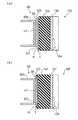
実施例では、テープTの硬さ,厚さ,幅に対応した硬さのプラテンゴム14を用いたが、さらにインクリボンRの性状に対応した硬さのプラテンゴム14を用いる構成も好適である。例えば、インクリボンRがワックス系のインクを使用し強く押圧されてインクが溶融しテープTにインクを付けてしまうといったタイプの場合、良好な印字を行なうためにテープTの硬さ,厚さ,幅に関わらず硬いプラテンゴム14を用いる構成がある。以下この構成について説明する。図23(a)はテープTの硬さ,厚さ幅に関わらず硬さが90度のプラテンゴム14Eを装着したプラテン12Eと印字ヘッド60とでテープTおよびインクリボンRを挟持した際の断面を示した説明図であり、図23(b)はテープTの硬さ,厚さ,幅に対応した硬さが40度のプラテンゴム14Fを装着したプラテン12Fと印字ヘッド60とを図22(a)と同一の断面で示した説明図である。
【0120】
図23(a)に示すように、プラテンゴム14Eは、印字ヘッド60の押圧により変形するが、硬度が90度と硬いので、その変形量が小さい。このため、プラテンゴム14Eは、テープTとインクリボンRと発熱体HTに押しつけるのみで、図23(b)に示すプラテンゴム14Fのように、テープTおよびインクリボンRをヘッド本体65の図中上端および下端の角EDに強く押しつけない。したがって、押圧によりテープTにインクを付着させやすいインクリボンRでも、テープTを汚すことがない。
【0121】
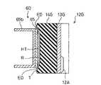
こうしたヘッド本体65の端部の角EDにテープTとインクリボンRが押しつけられることにより生じるテープTの汚れを防止する手法としては、上記の硬いプラテンゴム14Eを用いる他、図24に示すようにインクリボンRの幅をテープTの幅に関わらず発熱体HTの幅以上でヘッド本体65の幅以下にする構成、図25に示すようにプラテンゴム14Hの幅をテープTの幅に関わらず発熱体HTの幅以上でヘッド本体65の幅以下とする構成が考えられる。図24に示すように、インクリボンRの幅をテープTの幅に関わらず発熱体HTの幅以上でヘッド本体65の幅以下にすれば、テープTがヘッド本体65の端部の角EDに強く押されても、インクリボンRの幅がヘッド本体65の幅より狭いので、インクリボンRがテープTと共にヘッド本体65の端部の角EDに押されることがなく、テープTを汚すことがない。図25に示すように、プラテンゴム14Hの幅をテープTの幅に関わらず発熱体HTの幅以上でヘッド本体65の幅以下とすれば、テープTとインクリボンRは、ヘッド本体65の端部の角EDに押しつけられることがないので、インクでテープTを汚すことがない。
【0122】
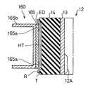
また、図26に示すように印字ヘッド160のヘッド本体165の両端部のプラテン側表面にプラテン側表面が滑らかなカーブとなる部材165aを設ける構成や、図27に示すように印字ヘッド260のヘッド本体265の両端部を滑らかなカーブとなるよう角EDを加工する構成も考えられる。図26に示す部材165aを設ける構成では、部材165aの材質は如何なる材質でもよく、例えば、発熱体HTの表面を形成するガラス質のグレースでもよい。このガラス質のグレースにより部材165aを形成する場合、部材165aと発熱体HTとを一体として形成しても良く、別体として形成してもよい。このように部材165aを用いる構成や、図27に示すヘッド本体265の両端部の角EDを滑らかなカーブとなるよう加工する構成とすれば、テープTとインクリボンRとが押圧されても単位面積当たりの押圧荷重が小さくなるので、インクリボンRのインクがテープTに付くほどの押圧荷重が得られず、テープTは汚れない。
【0123】
実施例では、インクリボンRの幅が広くなるほど柔らかなプラテンゴム14を用いたが、プラテンゴム14と印字ヘッド60との釣り合いの位置が一定となればよいので、インクリボンRの幅が広くなるほど外径を小さく形成してなるプラテン12を用いる構成も好適である。具体的には、インクリボンRの幅が広くなるほど薄いプラテンゴム14をプラテン12に装着すればよい。この際のプラテンゴム14の硬さはインクリボンRの幅に関わらず同一である。この構成とすれば、同一材料でプラテンゴム14を形成することができるので、ゴム自体の硬さを調整するための微妙な材料の調整をなくすことができ、形成したプラテンゴム14間の硬さのバラツキを小さくすことができる。
【0124】
また、インクリボンRの幅に対応した硬さおよび厚さのプラテンゴム14を用いる構成も好適である。即ち、実施例のインクリボンRの幅が広くなるほど柔らかなプラテンゴム14を用いる構成と、インクリボンRの幅が広くなるほど外径を小さく形成してなるプラテン12を用いる構成とを同時に適用した構成である。インクリボンRの幅に上述の構成の一方のみで対応する必要はなく、双方を併せて適用してもインクリボンRの幅に対応できるからである。
【0125】
以上本発明の実施例について説明したが、本発明はこうした実施例に何等限定されるものではなく、本発明の要旨を逸脱しない範囲内において、種々なる態様で実施し得ることは勿論である。例えば、実施例では、テープカートリッジに裏面に粘着層が設けられたテープTを収納したが、粘着層を後から貼り付けるタイプのテープ、印字面を保護する透明なシートを貼り合わせたラミネートタイプ、転写可能なインクを用いて印字される転写タイプ等の種々のタイプのテープを収納する構成も好適である。また、実施例では、テープカートリッジにインクリボン収納したが、インクリボンを収納しない構成としてもかまわない。
【0131】
【発明の効果】
以上説明した本発明の第1のテープカートリッジによれば、硬いプラテンを用いたので、幅の広い印字用テープとインクリボンとを用いても、印字用テープとインクリボンとを基板に強く押圧することがない。したがって、プラテンが印字用テープをインクリボンと共に印字ヘッドの基板に強く押圧することにより生じる印字用テープの汚れを防止することができる。
【0132】
本発明の第2のテープカートリッジによれば、インクリボンの幅を印字ヘッドを構成する印字部の幅以上で基板の幅以下にしたので、プラテンが印字用テープをインクリボンと共に印字ヘッドの基板に強く押圧することにより生じる印字用テープの汚れを防止することができる。
【0133】
本発明の第3のテープカートリッジによれば、プラテンの幅を印字ヘッドの印字部の幅以上で印字ヘッドの基板の幅以下にしたので、印字用テープがインクリボンと共に印字ヘッドの基板に強く押圧されることにより生じる印字用テープの汚れを防止することができる。
【0136】
本発明の第1ないし第3のテープカートリッジのプラテンを、中央部の外径が両端部の外径より大きな樽形に形成すれば、印字用テープやインクリボンの両側部が中央部より速く搬送されることを防止することができる。この結果、印字用テープやインクリボンがプラテンの一方の端部側にずれたり、印字用テープやインクリボンがよれることがなく、良好に印字することができる。また、プラテンの中央部の外径と両端部の外径とを等しく形成する場合に比して、製造の精度を低くしても中央部の外径が両端部の外径より小さいときに生じる上記不都合が生じないので、プラテンを容易に製造することができ、歩留りを高くすることができる。
【図面の簡単な説明】
【図1】本発明の実施例であるテープライタ1の平面図である。
【図2】同じくテープライタ1の右の側面図である。
【図3】実施例におけるテープカートリッジ10の組立構成を示す平面図である。
【図4】同じくその底面図である。
【図5】テープカートリッジ10における図3、A−A矢視端面図である。
【図6】テープカートリッジ10aを、インクリボンコア22,リボン巻取コア24およびプラテン12の中心を通る位置で破断して示す断面図である。
【図7】同じく、テープカートリッジ10bを示す断面図である。
【図8】プラテン12と印字ヘッド60とでテープTおよびインクリボンRを挟持する部分についての拡大説明図である。
【図9】テープTの硬さとプラテンゴム14の硬さとの関係を示すグラフである。
【図10】テープTの厚さとプラテンゴム14の硬さとの関係を示すグラフである。
【図11】テープTの幅とプラテンゴム14の硬さとの関係を示すグラフである。
【図12】プラテンゴム14の拡大断面図である。
【図13】インクリボンコア22の自由な回転を規制する構成を示す斜視図である。
【図14】印字ヘッド60で印字可能な状態のテープTおよびインクリボンRの様子を示す説明図である。
【図15】カートリッジ装着部50Aの構成を示す斜視図である。
【図16】ギヤトレインの構成と、印字ヘッド60を退避位置および印字位置の間で移動する機構とを説明する斜視図である。
【図17】印字ヘッド60の分解組立斜視図である。
【図18】CPU110を中心とした構成を示すブロック図である。
【図19】入力部50Cのキー配列の説明図である。
【図20】表示部50Dの構成を説明する説明図である。
【図21】テープライタ1が行なう処理の概要を示すフローチャートである。
【図22】軸13の外径とプラテンゴム14の厚さによりプラテン12の硬さを調整する様子を説明する説明図である。
【図23】硬度が90度および40度のプラテンゴム14E,14Fと印字ヘッド60とでテープTおよびインクリボンRを挟持した際の断面を示す断面図である。
【図24】幅を発熱体HTの幅以上でヘッド本体65の幅以下にしたインクリボンRとテープTとをプラテン12Gと印字ヘッド60とで挟持した際の断面図である。
【図25】幅を発熱体HTの幅以上でヘッド本体65の幅以下にしたプラテン12Hと印字ヘッド60とでインクリボンRとテープTを挟持した際の断面図である。
【図26】ヘッド本体165の両端部に部材165aを設けた印字ヘッド160とプラテン12とでインクリボンRとテープTを挟持した際の断面図である。
【図27】ヘッド本体165の両端部の角EDを加工した印字ヘッド160とプラテン12とでインクリボンRとテープTを挟持した際の断面図である。
【符号の説明】
1…テープライタ
10,10a,10b…テープカートリッジ
10A…テープ排出口
10B…ガイド部
12,12C〜12H…プラテン
12A…係合条
13,13C〜13H…軸
14,14A〜14H…プラテンゴム
14a…両端部
14b…中央部
16…天壁
16A,18A…嵌合孔
16C…ガイド突部
16G…嵌合孔部
18…底壁
18B…軸体
18C…嵌合孔部
18D,18H…係合片
18E…基端部
18G…嵌合孔部
18K…検出孔
18Ka,18Kb,18Kc…検出孔
20…テープコア
20A…フィルム
20B…軸孔
22…インクリボンコア
22A,24A…係合部
23…円環座金
24…リボン巻取コア
24B…係合条
24C…フランジ部
26…テープガイドピン
30…リボンガイドローラ
32…進入孔
34…ガイド壁
50A…カートリッジ装着部
50Aa…円筒部材
50B…プリンタ部
50C…入力部
50D…表示部
50Da…主表示部
50Db…インジケータ部
50E…拡張部
50Ea…外部入出力コネクタ
50F…制御回路部
50H…本体ケース
50J…電源スイッチ
50K…本体カバー
50L,50M…窓
50N…プラグ
50P…駆動機構
52…スライドボタン
54…カバーヒンジ
55…開閉検出スイッチ
60…印字ヘッド
60A…温度検出回路
60B…電圧検出回路
60C…ヘッドケース
61…ベースボード
62…回転フレーム
62A…立設部
62B…凸部
63A…カム部材
63Aa…回転軸
63Ab…凹部
63B…レバー回転軸
63C…ヘッド移動レバー
64…ヘッド回転軸
65…ヘッド本体
65b…放熱板
65ba…角孔
67b…ピン
68…フレキシブルケーブル
70A,70B…当接突起
72…プラテン駆動軸
72A…リム
72B,74B…突条
74…巻取コア駆動軸
74A…リム
80…ステッピングモータ
80A…回転軸
80B…クラッチアーム
80C…開口
81〜89…第1のギヤ〜第9のギヤ
90…テープカッター
90A…右端部
90B…左端部
91…固定刃
96…カッターボタン
96A…ピン
98…移動刃
99…検出スイッチ
102…カートリッジ判別スイッチ
102A,102B,102C…カートリッジ判別スイッチ
110…CPU
112…ヘッドランク判別部
112A,112B,112C…ジャンパー部
113…ACアダプタ
114…電源部
115…ジャック
116…表示部制御回路
116A…LCDコントローラ
118…マスクROM
120…プリンタコントローラ
122…モータドライバ
160…印字ヘッド
165…ヘッド本体
165a…部材
260…印字ヘッド
265…ヘッド本体[0001]
[Industrial application fields]
The present invention relates to a tape cartridge, and in particular, is detachable from a printing apparatus equipped with a print head, and is mounted on a printing apparatus of a specific type among two or more types of printing tapes having different properties. The present invention relates to two or more types of tape cartridges provided with a platen that holds the printing tape between the print head and the print head so as to allow printing.
[0002]
[Prior art]
2. Description of the Related Art Conventionally, a printing apparatus that prints a desired character string on the surface of an adhesive tape whose adhesive is previously applied to the back surface is known. According to this type of printing device, the title and title name can be neatly printed on the tape surface on the spot, and then easily attached to the back cover of the document file or the back of the video tape. Widely used for both business and home use.
[0003]
These printing apparatuses need to be reduced in size and weight, and various improvements are made for that purpose. One of the major points is the improvement of the printing unit that requires a large area occupied mechanically, and a structure that has a platen on the tape cartridge side that enables printing on the tape in cooperation with the print head is adopted. Is known. The platen is provided on the tape cartridge side because the print head holds the printing tape with the platen when printing is performed. When replacing the tape cartridge, the tape cartridge can be easily replaced by simply retracting the print head. This is to make it possible.
[0004]
Such tape cartridges are commercially available with various types of tapes of different materials, widths, colors, etc. and ink ribbons used for printing on these tapes. Select the tape cartridge that contains the tape and install it in the printer.
[0005]
[Problems to be solved by the invention]
However, there is a problem that a tape cartridge containing such different types of tapes cannot be printed satisfactorily depending on the printing device and the type of tape. For example, if you install a tape cartridge that contains a thick tape in a printing device that uses thin tape as a standard specification, or conversely, if you install a tape cartridge that contains a thin tape in a printing device that uses thick tape as a standard specification, There are cases where the contact state with the tape is different and printing cannot be performed satisfactorily. In order to solve this problem, a method of providing a printing device with a mechanism for adjusting the position of the print head corresponding to the thickness of the tape is also conceivable. Occurs. In this method, when the tape cartridge is loaded, it is checked whether the adjustment mechanism of the printing apparatus corresponds to the thickness of the tape stored in the loaded tape cartridge. This also causes a problem that the user feels troublesome to use. Such a problem occurs not only with respect to the thickness of the tape stored in the tape cartridge but also with respect to the width and hardness of the tape, the width of the ink ribbon, and the like.
[0006]
Further, depending on the ink ribbon and the platen stored in the tape cartridge, there is also a problem that the tape is soiled by ink of the ink ribbon and printing cannot be performed satisfactorily. When the tape cartridge is mounted on the printing apparatus, the tape and the ink ribbon are pressed against the platen by the print head. If the width of the tape and the ink ribbon is wider than the width of the print head and the platen is made of a relatively soft material, the platen will be greatly deformed by the press of the print head and the tape and ink ribbon will be Press strongly against the corner. Ink ribbons of the type that cause ink to adhere to the tape by strong pressing may cause undesired ink to be applied to the tape by pressing against the corners of the side of the print head.
[0007]
The tape cartridge of the present invention has the following configuration in order to solve such problems and to print well regardless of the type of tape or ink ribbon.
[0013]
[Means for Solving the Problems]
The first tape cartridge of the present invention is
The printing tape is detachably attached to a printing apparatus having a printing head, and is disposed between the printing tape, an ink ribbon used for printing on the printing tape, and the printing head when mounted on the printing apparatus. A tape cartridge containing a platen that can be printed and
The printing tape and the ink ribbon sandwiched between the platen and the print head are configured to be conveyed in the rotation direction of the platen as the platen rotates.
The print head includes a printing unit that performs printing on the printing tape, and a substrate on which the printing unit is mounted.
The printing tape and the ink ribbon are formed wider than the substrate,
The platen is
The width of the platen in the same direction as the width direction of the ink ribbon is wider than the width in the same direction of the substrate,
When the printing tape and the ink ribbon are sandwiched between the print head and the rubber on the surface thereof, the deformation due to the pressing of the print head is caused by the pressing of the corners of the printing head. The gist is that the ink is formed to have a hardness that is equal to or less than the deformation amount to which ink does not adhere.
[0014]
First of the present invention2The tape cartridge
The printing tape is detachably attached to a printing apparatus having a printing head, and is disposed between the printing tape, an ink ribbon used for printing on the printing tape, and the printing head when mounted on the printing apparatus. And a tape cartridge containing a platen for holding the ink ribbon so as to be printable,
The print head includes a printing unit that performs printing on the printing tape, and a substrate on which the printing unit is mounted.
The gist of the ink ribbon is that it is formed to have a width that is greater than or equal to the width of the print portion and less than or equal to the width of the substrate.
[0015]
First of the present invention3The tape cartridge
A tape cartridge that is detachable from a printing apparatus having a print head, and that contains a printing tape and a platen that holds the printing tape between the print head and the print head when it is attached to the printing apparatus. There,
The print head includes a printing unit that performs printing on the printing tape, and a substrate on which the printing unit is mounted.
The gist of the platen is that the width of the platen is not less than the width of the printing portion and not more than the width of the substrate.
[0018]
In the first to third tape cartridges of the present invention, the platen can be formed in a barrel shape in which the outer diameter of the central portion is larger than the outer diameters of both end portions.
[0024]
[Action]
The first tape cartridge of the present invention configured as described above has a platen whose surface is wider than the width of the substrate of the print head and when the print tape and ink ribbon are sandwiched between the plate and the print head. The printing tape is formed so that the deformation due to the pressing of the print head is less than the deformation amount at which the ink of the ink ribbon does not adhere to the printing tape due to the pressing of the corner of the printing head. The printing tape is prevented from being soiled by being strongly pressed against the substrate together with the ink ribbon.
[0025]
First of the present invention2In this tape cartridge, the width of the ink ribbon is not less than the width of the printing portion constituting the print head and not more than the width of the substrate, so that the printing tape and the ink ribbon are strongly pressed against the substrate of the print head. Prevents smudges on the printing tape caused by.
[0026]
First of the present invention3In this tape cartridge, the width of the platen is not less than the width of the print section of the print head and not more than the width of the print head substrate, so that the print tape and the ink ribbon are strongly pressed against the print head substrate. Prevents smudges on the printing tape caused by.
[0028]
If the platens of the first to third tape cartridges of the present invention are formed in a barrel shape in which the outer diameter of the central part is larger than the outer diameters of both ends, both sides of the printing tape and ink ribbon are faster than the central part. Since it is not conveyed, the printing tape and ink ribbon are not displaced toward one end of the platen, and the printing tape and ink ribbon are not kinked, and good printing is possible.
[0029]
【Example】
In order to further clarify the configuration and operation of the present invention described above, a tape cartridge which is a preferred embodiment of the present invention and a tape writer which detachably incorporates the tape cartridge and prints on the tape will be described below.
[0030]
1 is a plan view showing the appearance of the
[0031]
As shown in the figure, the
[0032]
When the
[0033]
After closing the
[0034]
Although not shown, a battery storage unit is provided on the back surface of the
[0035]
Next, the structure and function of the
[0036]
[Table 1]
The
[0038]
[Table 2]
6 and 7 show an example of a tape cartridge in which the platen rubber width is changed according to the tape width. FIG. 6 is a cross-sectional view showing a
[0040]
The platen rubber thickness is changed in accordance with the tape thickness. The
[0041]
Table 3 shows an example in which the hardness of the
[0042]
[Table 3]
As shown in Table 3, the
[0044]
In the embodiment, the surface roughness of the
[0045]
FIG. 12 is a cross-sectional view showing a cross section obtained by cutting the
[0046]
The outer periphery of the upper and lower ends of the
[0047]
In addition, a
[0048]
The
[0049]
As shown in FIG. 5, the
[0050]
The tape T wound and stored in the
[0051]
Since the
[0052]
As shown in FIGS. 6 and 7, the
[0053]
3 and 4, the
[0054]
The ink ribbon R that is wound and stored in the
[0055]
The ribbon take-
[0056]
Further, in order to prevent unexpected rotation of the ribbon take-
[0057]
The engagement between the
[0058]
The ink ribbon R wound up on such a
[0059]
When the ribbon width of the ink ribbon R is equal to the height of the tape cartridge 10 (see FIG. 7), the ink ribbon R is guided by the
[0060]
In this embodiment, the
[0061]
[Table 4]
As shown in Table 4, the
[0063]
In a state where printing can be performed by the
[0064]
Therefore, by using the
[0065]
As described above, there are 600 types of
[0066]
The
[0067]
The
[0068]
Mounting or replacement of the
[0069]
[0070]
Next, a transmission mechanism that transmits the rotation of the stepping
[0071]
By the rotation of the
[0072]
The rotation of the
[0073]
On the outer circumferences of the
[0074]
Thus, when the tape T is conveyed together with printing, the tape T is sent out from the
[0075]
In this embodiment, this problem is avoided by the one-way clutch constituted by the described
[0076]
The printed tape T discharged from the
[0077]
Further, a moving
[0078]
Next, the
[0079]
A rotating shaft 63Aa of the cam member 63A is connected to a lower end of a
[0080]
FIG. 17 shows a detailed exploded perspective view of the
[0081]
The
[0082]
Next, details of the
[0083]
As shown in FIG. 19, the
[0084]
Each of these keys is assigned to an 8 × 8 matrix. That is, as seen from the
[0085]
The detection output from the opening /
[0086]
The ports PH, PM, and PL of the
[0087]
Since printing by the
[0088]
A
[0089]
A signal from the contact of the
[0090]
The
[0091]
The
[0092]
Character dot data read from the
[0093]
The
[0094]
The main display unit 50Da is used as a liquid crystal display panel capable of displaying 16 dots high by 96 dots wide. In this embodiment, since characters at the time of character input and editing are displayed on the main display unit using a character font having a width of 16 × 16 dots, a display of 6 characters × 1 line is possible. Further, when displaying each character, the processing state of the
[0095]
Further, since the main display unit 50Da is in a dot matrix format and the display contents can be freely controlled, when the “layout” key of the
[0096]
The
[0097]
The
[0098]
In addition to the components described above, the
[0099]
Various programs for executing the above-described operations are stored in the internal ROM of the
[0100]
Next, processing executed by the
[0101]
When this processing routine is started, the processing mode is first determined (step S200). If a specific mode is not designated, the character input mode is determined and print data is input (step S210). The input of the print data is realized by the process of directly inputting the key input for alphanumeric characters and the like, and for the kana / kanji characters, the results of converting the kana characters input from the
[0102]
Since the print data buffer has a maximum of 125 characters, if more characters are input from the
[0103]
Then, using the print data in the print data buffer, as part of the character display process (step S230), the “line number” of the indicator section 50Db corresponding to the number of lines of the print data is shown by a flowchart (not shown). The display body t is lit up, and the display body t corresponding to the line position where the cursor is positioned is flashed, and then the print data at the edit line position is displayed on the dot matrix on the main display section 50Da. Is displayed.
[0104]
By this processing, the user can confirm the total number of lines of print data currently being edited and the line position where the cursor is located by the “line number” of the indicator section 50Db. After performing such a display process (step S230), the process goes to “NEXT” and this process routine is temporarily terminated.
[0105]
Next, the print mode will be described. When the print mode is designated, the detection signal of the
[0106]
When the print font to be used for printing each line is determined, the print font corresponding to the character code of the character string to be printed is sequentially read from the
[0107]
The basic usage mode of handling / operation of the
[0108]
According to the
[0109]
Therefore, it is not necessary to provide the
[0110]
Further, since the
[0111]
Further, since the
[0112]
Thus, by using the
[0113]
Further, in the embodiment, since the
[0114]
Of course, the
[0115]
In the embodiment, the tape feed amount of one step of the stepping
[0116]
In the embodiment, the hardness of the
[0117]
As shown in the drawing, the
[0118]
If the hardness of the
[0119]
In the embodiment, the
[0120]
As shown in FIG. 23A, the
[0121]
In order to prevent the tape T and the ink ribbon R from being pressed against the corner ED of the end of the head
[0122]
In addition, as shown in FIG. 26, the platen side surface of the both ends of the head
[0123]
In the embodiment, the
[0124]
A configuration using a
[0125]
The embodiments of the present invention have been described above. However, the present invention is not limited to these embodiments, and it is needless to say that the present invention can be implemented in various modes without departing from the gist of the present invention. For example, in the example, the tape T having the adhesive layer provided on the back surface is stored in the tape cartridge, but the tape of the type to which the adhesive layer is attached later, the laminate type in which the transparent sheet for protecting the printing surface is attached, A configuration in which various types of tape such as a transfer type printed using a transferable ink is accommodated is also suitable. In the embodiment, the ink ribbon is stored in the tape cartridge. However, the ink ribbon may not be stored.
[0131]
【The invention's effect】
Explained aboveFirst of the present invention1According to this tape cartridge, since the hard platen is used, the printing tape and the ink ribbon are not strongly pressed against the substrate even when the wide printing tape and the ink ribbon are used. Accordingly, it is possible to prevent the printing tape from being soiled when the platen strongly presses the printing tape together with the ink ribbon against the substrate of the print head.
[0132]
First of the present invention2According to this tape cartridge, since the width of the ink ribbon is set to be equal to or larger than the width of the printing portion constituting the print head and smaller than the width of the substrate, the platen strongly presses the printing tape together with the ink ribbon against the print head substrate. It is possible to prevent the printing tape from becoming dirty.
[0133]
First of the present invention3According to this tape cartridge, since the width of the platen is not less than the width of the print portion of the print head and not more than the width of the substrate of the print head, the print tape is strongly pressed together with the ink ribbon against the substrate of the print head. It is possible to prevent the printing tape from being stained.
[0136]
If the platen of the first to third tape cartridges of the present invention is formed in a barrel shape in which the outer diameter of the central part is larger than the outer diameters of both ends, both sides of the printing tape and ink ribbon are transported faster than the central part. Can be prevented. As a result, the printing tape and the ink ribbon are not displaced toward one end side of the platen, and the printing tape and the ink ribbon are not swung. Also, it occurs when the outer diameter of the central part is smaller than the outer diameters of both end parts even if the manufacturing accuracy is lowered, compared with the case where the outer diameter of the central part of the platen is equal to the outer diameters of both end parts. Since the above inconvenience does not occur, the platen can be easily manufactured and the yield can be increased.
[Brief description of the drawings]
FIG. 1 is a plan view of a
2 is a right side view of the
FIG. 3 is a plan view showing an assembly configuration of the
FIG. 4 is a bottom view of the same.
5 is an end view of the
6 is a cross-sectional view of the
FIG. 7 is a cross-sectional view showing the
FIG. 8 is an enlarged explanatory view of a portion where the tape T and the ink ribbon R are sandwiched between the
FIG. 9 is a graph showing the relationship between the hardness of the tape T and the hardness of the
10 is a graph showing the relationship between the thickness of the tape T and the hardness of the
FIG. 11 is a graph showing the relationship between the width of the tape T and the hardness of the
12 is an enlarged cross-sectional view of the
13 is a perspective view showing a configuration for restricting free rotation of the
FIG. 14 is an explanatory diagram showing a state of the tape T and the ink ribbon R in a state where printing can be performed by the
FIG. 15 is a perspective view showing a configuration of a
FIG. 16 is a perspective view illustrating a configuration of the gear train and a mechanism for moving the
17 is an exploded perspective view of the
FIG. 18 is a block diagram showing a configuration centering on a CPU.
FIG. 19 is an explanatory diagram of a key layout of the
FIG. 20 is an explanatory diagram illustrating a configuration of a
FIG. 21 is a flowchart showing an outline of processing performed by the
FIG. 22 is an explanatory diagram for explaining how the hardness of the
23 is a cross-sectional view showing a cross section when the tape T and the ink ribbon R are sandwiched between the
24 is a cross-sectional view when an ink ribbon R and a tape T having a width not less than the width of the heating element HT and not more than the width of the
25 is a cross-sectional view when the ink ribbon R and the tape T are sandwiched between the
26 is a cross-sectional view when the ink ribbon R and the tape T are sandwiched between the
FIG. 27 is a cross-sectional view when the ink ribbon R and the tape T are sandwiched between the
[Explanation of symbols]
1 ... Tape writer
10, 10a, 10b ... tape cartridge
10A ... Tape outlet
10B ... Guide part
12, 12C-12H ... Platen
12A ... engagement line
13, 13C-13H ... axis
14, 14A-14H ... Platen rubber
14a ... both ends
14b ... Central part
16 ... Heavenly wall
16A, 18A ... Fitting hole
16C ... guide protrusion
16G ... fitting hole
18 ... Bottom wall
18B ... Shaft
18C ... fitting hole
18D, 18H ... engagement piece
18E ... Base end
18G ... fitting hole
18K ... Detection hole
18Ka, 18Kb, 18Kc ... detection hole
20 ... tape core
20A ... Film
20B ... shaft hole
22 ... Ink ribbon core
22A, 24A ... engaging portion
23 ... A ring washer
24 ... Ribbon winding core
24B ... engagement strip
24C ... Flange
26 ... Tape guide pin
30 ... Ribbon guide roller
32 ... Entry hole
34 ... Guide wall
50A ... cartridge mounting part
50Aa ... Cylindrical member
50B ... Printer section
50C ... Input section
50D ... Display section
50 Da ... Main display
50Db ... Indicator section
50E ... Extension
50Ea ... External input / output connector
50F ... Control circuit section
50H ... Body case
50J ... Power switch
50K ... Body cover
50L, 50M ... Window
50N ... Plug
50P ... Drive mechanism
52 ... Slide button
54 ... Cover hinge
55. Open / close detection switch
60 ... Print head
60A ... Temperature detection circuit
60B ... Voltage detection circuit
60C ... Head case
61 ... Baseboard
62 ... Rotating frame
62A ... Standing part
62B ... convex portion
63A ... Cam member
63Aa ... Rotating shaft
63Ab ... recess
63B ... Lever rotation axis
63C ... Head movement lever
64 ... head rotation axis
65 ... head body
65b ... Heat sink
65ba ... square hole
67b ... pin
68 ... Flexible cable
70A, 70B ... abutment protrusion
72 ... Platen drive shaft
72A ... Rim
72B, 74B ... ridges
74 ... Winding core drive shaft
74A ... Rim
80 ... Stepping motor
80A ... Rotating shaft
80B ... Clutch arm
80C ... Opening
81-89 ... 1st gear-9th gear
90 ... tape cutter
90A ... Right end
90B ... Left end
91 ... Fixed blade
96 ... Cutter button
96A ... pin
98 ... Moving blade
99 ... Detection switch
102 ... Cartridge discrimination switch
102A, 102B, 102C ... cartridge discrimination switch
110 ... CPU
112 ... Head rank discriminator
112A, 112B, 112C ... Jumper part
113 ... AC adapter
114 ... Power supply
115 ... Jack
116: Display unit control circuit
116A ... LCD controller
118 ... Mask ROM
120: Printer controller
122 ... Motor driver
160: Print head
165 ... Head body
165a ... member
260 ... print head
265 ... Head body
Claims (3)
Translated fromJapanese前記プラテンと前記印字ヘッドとにより挟持された前記印字用テープと前記インクリボンとは、前記プラテンの回転に伴って、該プラテンの回転方向に搬送されるように構成され、
前記印字ヘッドは、前記印字用テープに印字を行なう印字部と、該印字部が装着される基板とからなり、
前記印字用テープおよび前記インクリボンは、幅が前記基板より広く形成され、
前記プラテンは、
前記インクリボンの幅方向と同方向のプラテンの幅を、前記基板の同方向の幅より広く、
前記印字ヘッドとで前記印字用テープおよび前記インクリボンを挟持したとき、その表面のゴムを、該印字ヘッドの押圧による変形が、前記印字ヘッドの隅部の押圧により、前記印字テープにインクリボンのインクが付着しない変形量以下となる硬さに形成してなる
テープカートリッジ。The printing tape is detachably attached to a printing apparatus having a printing head, and is disposed between the printing tape, an ink ribbon used for printing on the printing tape, and the printing head when mounted on the printing apparatus. A tape cartridge containing a platen that can be printed and
The printing tape and the ink ribbon sandwiched between the platen and the print head are configured to be conveyed in the rotation direction of the platen as the platen rotates.
The print head includes a printing unit that performs printing on the printing tape, and a substrate on which the printing unit is mounted.
The printing tape and the ink ribbon are formed wider than the substrate,
The platen is
The width of the platen in the same direction as the width direction of the ink ribbon is wider than the width in the same direction of the substrate,
When the printing tape and the ink ribbon are sandwiched between the print head and the rubber on the surface thereof, the deformation due to the pressing of the printing head is caused by the pressing of the corner of the printing head. Tape cartridge formed with a hardness that is less than the amount of deformation to which ink does not adhere.
前記プラテンと前記印字ヘッドとにより挟持された前記印字用テープと前記インクリボンとは、前記プラテンの回転に伴って、該プラテンの回転方向に搬送されるように構成され、
前記印字ヘッドは、前記印字用テープに印字を行なう印字部と、該印字部が装着される基板とからなり、
前記インクリボンは、その幅を、前記インクリボンの幅方向と同方向の印字部の幅以上で前記基板の同方向の幅以下に形成してなるテープカートリッジ。The printing tape is detachably attached to a printing apparatus having a printing head, and is disposed between the printing tape, an ink ribbon used for printing on the printing tape, and the printing head when mounted on the printing apparatus. And a tape cartridge containing a platen for holding the ink ribbon so as to be printable,
The printing tape and the ink ribbon sandwiched between the platen and the print head are configured to be conveyed in the rotation direction of the platen as the platen rotates.
The print head includes a printing unit that performs printing on the printing tape, and a substrate on which the printing unit is mounted.
The ink cartridge is a tape cartridge formed so that the width of the ink ribbon is equal to or greater than the width of the printing portion in the same direction as the width direction of the ink ribbon and equal to or less than the width of the substrate in the same direction.
前記プラテンと前記印字ヘッドとにより挟持された前記印字用テープと前記インクリボンとは、前記プラテンの回転に伴って、該プラテンの回転方向に搬送されるように構成され、
前記印字ヘッドは、前記印字用テープに印字を行なう印字部と、該印字部が装着される基板とからなり、
前記プラテンは、前記インクリボンの幅方向と同方向のプラテンの幅を、前記基板の同方向の幅以下に形成してなるテープカートリッジ。A tape cartridge that is detachable from a printing apparatus having a print head, and that contains a printing tape and a platen that holds the printing tape between the print head and the print head when it is attached to the printing apparatus. There,
The printing tape and the ink ribbon sandwiched between the platen and the print head are configured to be conveyed in the rotation direction of the platen as the platen rotates.
The print head includes a printing unit that performs printing on the printing tape, and a substrate on which the printing unit is mounted.
The platen is a tape cartridge in which the width of the platen in the same direction as the width direction of the ink ribbon is formed to be equal to or smaller than the width in the same direction of the substrate.
Priority Applications (8)
| Application Number | Priority Date | Filing Date | Title |
|---|---|---|---|
| JP20917294AJP3968130B2 (en) | 1994-08-09 | 1994-08-09 | Tape cartridge |
| TW085215911UTW336541U (en) | 1994-08-09 | 1995-07-25 | Tape cartridges |
| EP95112515AEP0696510B1 (en) | 1994-08-09 | 1995-08-09 | Tape cartridges |
| US08/513,139US5702192A (en) | 1994-08-09 | 1995-08-09 | Tape cartridges |
| DE69526160TDE69526160T2 (en) | 1994-08-09 | 1995-08-09 | tape Cartridges |
| US08/831,669US5918992A (en) | 1994-08-09 | 1997-04-10 | Tape cartridges |
| US08/909,084US6045276A (en) | 1994-08-09 | 1997-08-14 | Tape cartridges |
| US09/390,523US6149328A (en) | 1994-08-09 | 1999-09-03 | Tape cartridges |
Applications Claiming Priority (1)
| Application Number | Priority Date | Filing Date | Title |
|---|---|---|---|
| JP20917294AJP3968130B2 (en) | 1994-08-09 | 1994-08-09 | Tape cartridge |
Related Child Applications (1)
| Application Number | Title | Priority Date | Filing Date |
|---|---|---|---|
| JP2003008721ADivisionJP3753697B2 (en) | 2003-01-16 | 2003-01-16 | Tape cartridge |
Publications (2)
| Publication Number | Publication Date |
|---|---|
| JPH0852913A JPH0852913A (en) | 1996-02-27 |
| JP3968130B2true JP3968130B2 (en) | 2007-08-29 |
Family
ID=16568532
Family Applications (1)
| Application Number | Title | Priority Date | Filing Date |
|---|---|---|---|
| JP20917294AExpired - LifetimeJP3968130B2 (en) | 1994-08-09 | 1994-08-09 | Tape cartridge |
Country Status (5)
| Country | Link |
|---|---|
| US (4) | US5702192A (en) |
| EP (1) | EP0696510B1 (en) |
| JP (1) | JP3968130B2 (en) |
| DE (1) | DE69526160T2 (en) |
| TW (1) | TW336541U (en) |
Cited By (1)
| Publication number | Priority date | Publication date | Assignee | Title |
|---|---|---|---|---|
| KR101450685B1 (en)* | 2010-11-11 | 2014-10-14 | 세이코 엡슨 가부시키가이샤 | Tape reel device and tape cartridge including the same |
Families Citing this family (28)
| Publication number | Priority date | Publication date | Assignee | Title |
|---|---|---|---|---|
| JP3968130B2 (en)* | 1994-08-09 | 2007-08-29 | セイコーエプソン株式会社 | Tape cartridge |
| JP4543601B2 (en)* | 1999-08-06 | 2010-09-15 | ブラザー工業株式会社 | Tape supply cartridge |
| US6428225B1 (en) | 2000-02-18 | 2002-08-06 | Premark Feg L.L.C. | Printer cassette with label stock tensioner arm and associated printer |
| US20060159914A1 (en)* | 2005-01-14 | 2006-07-20 | Tapemorr, Llc | Branded adhesive tape |
| GB0521754D0 (en)* | 2005-10-25 | 2005-11-30 | Esselte | Tape printing apparatus |
| US20070257471A1 (en)* | 2006-05-08 | 2007-11-08 | Baby Planet Llc | Universal Infant Carrier Transport |
| US20080226373A1 (en)* | 2007-03-12 | 2008-09-18 | Brother Kogyo Kabushiki Kaishi | Lettering tape, tape cassette, tape printer |
| CN102481795A (en)* | 2009-04-28 | 2012-05-30 | 迪默公司 | Cartridge for label printer |
| JP5556435B2 (en)* | 2010-06-25 | 2014-07-23 | セイコーエプソン株式会社 | Tape cartridge |
| JP5429090B2 (en)* | 2010-07-16 | 2014-02-26 | セイコーエプソン株式会社 | Tape cartridge |
| DE102012204594A1 (en)* | 2011-10-12 | 2013-04-18 | Tesa Se | dispensers |
| US10875335B2 (en)* | 2013-06-27 | 2020-12-29 | Videojet Technologies Inc. | Stepper motor driven print head |
| JP5731607B2 (en)* | 2013-09-30 | 2015-06-10 | セイコーエプソン株式会社 | Tape cartridge |
| JP5731682B2 (en)* | 2014-03-10 | 2015-06-10 | セイコーエプソン株式会社 | Tape cartridge |
| JP6113207B2 (en)* | 2014-03-24 | 2017-04-12 | セイコーエプソン株式会社 | Tape cartridge |
| JP5931232B2 (en)* | 2015-01-26 | 2016-06-08 | セイコーエプソン株式会社 | Tape cartridge |
| JP5849164B2 (en)* | 2015-01-26 | 2016-01-27 | セイコーエプソン株式会社 | Tape cartridge |
| JP6361522B2 (en)* | 2015-02-06 | 2018-07-25 | セイコーエプソン株式会社 | Ribbon feeder and tape printing apparatus having the same |
| JP6297514B2 (en)* | 2015-03-19 | 2018-03-20 | セイコーエプソン株式会社 | Tape cartridge |
| JP6166818B2 (en)* | 2016-04-25 | 2017-07-19 | セイコーエプソン株式会社 | Tape cartridge |
| GB2559404A (en)* | 2017-02-06 | 2018-08-08 | Dover Europe Sarl | A printing apparatus |
| JP6798360B2 (en)* | 2017-03-01 | 2020-12-09 | セイコーエプソン株式会社 | Tape printing equipment |
| JP7017078B2 (en)* | 2017-04-13 | 2022-02-08 | セイコーエプソン株式会社 | Head pressurizing mechanism and tape printing device |
| CN108724921B (en)* | 2017-04-13 | 2020-05-15 | 精工爱普生株式会社 | Head Pressing Mechanism and Belt Printing Unit |
| JP6498805B2 (en)* | 2018-02-19 | 2019-04-10 | セイコーエプソン株式会社 | Tape cartridge |
| JP6452869B2 (en)* | 2018-02-19 | 2019-01-16 | セイコーエプソン株式会社 | Tape cartridge |
| JP7105688B2 (en)* | 2018-03-29 | 2022-07-25 | セイコーエプソン株式会社 | ribbon cartridge |
| JP7272053B2 (en)* | 2019-03-28 | 2023-05-12 | セイコーエプソン株式会社 | tape printer |
Family Cites Families (20)
| Publication number | Priority date | Publication date | Assignee | Title |
|---|---|---|---|---|
| JPS60151077A (en)* | 1984-01-19 | 1985-08-08 | Canon Inc | Platen |
| JPS60222268A (en)* | 1984-04-20 | 1985-11-06 | Hitachi Ltd | Thermal color printer |
| JPS60242059A (en)* | 1984-05-16 | 1985-12-02 | Ricoh Co Ltd | Heat sensitive printer |
| JPS6195542U (en)* | 1984-11-28 | 1986-06-19 | ||
| JPS62201274A (en)* | 1986-03-01 | 1987-09-04 | Dainippon Printing Co Ltd | Thermal sublimation transfer printer |
| US4927278A (en)* | 1987-12-29 | 1990-05-22 | Brother Kogyo Kabushiki Kaisha | Tape cassette and tape printer for use therewith |
| US4836697A (en)* | 1988-03-21 | 1989-06-06 | Kroy Inc. | Automated thermal transfer device and control system therefor |
| US5022771A (en)* | 1989-07-17 | 1991-06-11 | Kroy Inc. | Thermal printing apparatus and tape supply cartridge therefor |
| JPH0359842A (en)* | 1989-07-28 | 1991-03-14 | Seiko Epson Corp | Recorder |
| JPH03124477A (en)* | 1989-10-06 | 1991-05-28 | Brother Ind Ltd | ribbon cassette |
| GB2250716A (en)* | 1990-11-20 | 1992-06-17 | Esselte Dymo Nv | Lid-responsive release of thermal printhead in printer using cassetted ink-ribbon. |
| JP2508933B2 (en)* | 1991-03-28 | 1996-06-19 | ブラザー工業株式会社 | Tape printing device |
| JPH0528645U (en)* | 1991-09-20 | 1993-04-16 | ブラザー工業株式会社 | Tape printer |
| JP2893499B2 (en)* | 1992-10-13 | 1999-05-24 | セイコーエプソン株式会社 | Tape cartridge and tape writer |
| JPH0679550A (en)* | 1992-08-31 | 1994-03-22 | Fujitsu Ten Ltd | Feeding device of screw with washer |
| CA2107759A1 (en)* | 1992-10-06 | 1994-04-07 | Masahiko Nunokawa | Tape printing device |
| US5595447A (en)* | 1992-10-13 | 1997-01-21 | Seiko Epson Corporation | Tape cartridge and printing device having print medium cartridge |
| JP3059842B2 (en) | 1992-11-16 | 2000-07-04 | 三洋電機株式会社 | Non-aqueous electrolyte battery |
| US5503482A (en)* | 1993-12-29 | 1996-04-02 | Brother Kogyo Kabushiki Kaisha | Tape printing apparatus |
| JP3968130B2 (en)* | 1994-08-09 | 2007-08-29 | セイコーエプソン株式会社 | Tape cartridge |
- 1994
- 1994-08-09JPJP20917294Apatent/JP3968130B2/ennot_activeExpired - Lifetime
- 1995
- 1995-07-25TWTW085215911Upatent/TW336541U/enunknown
- 1995-08-09USUS08/513,139patent/US5702192A/ennot_activeExpired - Lifetime
- 1995-08-09DEDE69526160Tpatent/DE69526160T2/ennot_activeExpired - Fee Related
- 1995-08-09EPEP95112515Apatent/EP0696510B1/ennot_activeExpired - Lifetime
- 1997
- 1997-04-10USUS08/831,669patent/US5918992A/ennot_activeExpired - Lifetime
- 1997-08-14USUS08/909,084patent/US6045276A/ennot_activeExpired - Lifetime
- 1999
- 1999-09-03USUS09/390,523patent/US6149328A/ennot_activeExpired - Lifetime
Cited By (1)
| Publication number | Priority date | Publication date | Assignee | Title |
|---|---|---|---|---|
| KR101450685B1 (en)* | 2010-11-11 | 2014-10-14 | 세이코 엡슨 가부시키가이샤 | Tape reel device and tape cartridge including the same |
Also Published As
| Publication number | Publication date |
|---|---|
| EP0696510A1 (en) | 1996-02-14 |
| EP0696510B1 (en) | 2002-04-03 |
| US6045276A (en) | 2000-04-04 |
| JPH0852913A (en) | 1996-02-27 |
| TW336541U (en) | 1998-07-11 |
| US6149328A (en) | 2000-11-21 |
| US5918992A (en) | 1999-07-06 |
| DE69526160T2 (en) | 2002-09-26 |
| DE69526160D1 (en) | 2002-05-08 |
| US5702192A (en) | 1997-12-30 |
Similar Documents
| Publication | Publication Date | Title |
|---|---|---|
| JP3968130B2 (en) | Tape cartridge | |
| JP2736950B2 (en) | Printing equipment | |
| JP2879636B2 (en) | Printing sheet cartridge and printing equipment | |
| JP3753697B2 (en) | Tape cartridge | |
| JP3041516B2 (en) | Print sheet cartridge | |
| JP3008345B2 (en) | Printing device | |
| JP2995555B2 (en) | Printing device | |
| JP2893499B2 (en) | Tape cartridge and tape writer | |
| JP3420544B2 (en) | Tape cartridge | |
| JP3041518B2 (en) | Printing device | |
| JP3864066B2 (en) | Tape printer | |
| JP3041381U (en) | Tape cartridge | |
| JP3731749B2 (en) | Tape printer | |
| JP2916912B2 (en) | Printing equipment | |
| JP3129546B2 (en) | Ink ribbon cartridge and printing equipment | |
| JP2002137475A (en) | Tape printer | |
| JP3002817B2 (en) | Tape printer | |
| JP3002815B2 (en) | Print sheet cartridge | |
| JP3481827B2 (en) | Tape cartridge | |
| JP3042209U (en) | Tape cartridge | |
| JP3041517B2 (en) | Print sheet cartridge | |
| JP3753573B2 (en) | Printing device and printing control method | |
| JP3091175B2 (en) | Tape printer | |
| JP3041519B2 (en) | Tape cartridge | |
| JP3481826B2 (en) | Tape cartridge |
Legal Events
| Date | Code | Title | Description |
|---|---|---|---|
| A711 | Notification of change in applicant | Free format text:JAPANESE INTERMEDIATE CODE: A711 Effective date:20050905 | |
| A521 | Written amendment | Free format text:JAPANESE INTERMEDIATE CODE: A523 Effective date:20050927 | |
| A521 | Written amendment | Free format text:JAPANESE INTERMEDIATE CODE: A523 Effective date:20060220 | |
| A521 | Written amendment | Free format text:JAPANESE INTERMEDIATE CODE: A523 Effective date:20061027 | |
| A61 | First payment of annual fees (during grant procedure) | Free format text:JAPANESE INTERMEDIATE CODE: A61 Effective date:20070604 | |
| R150 | Certificate of patent or registration of utility model | Free format text:JAPANESE INTERMEDIATE CODE: R150 | |
| FPAY | Renewal fee payment (event date is renewal date of database) | Free format text:PAYMENT UNTIL: 20110608 Year of fee payment:4 | |
| FPAY | Renewal fee payment (event date is renewal date of database) | Free format text:PAYMENT UNTIL: 20110608 Year of fee payment:4 | |
| FPAY | Renewal fee payment (event date is renewal date of database) | Free format text:PAYMENT UNTIL: 20120608 Year of fee payment:5 | |
| FPAY | Renewal fee payment (event date is renewal date of database) | Free format text:PAYMENT UNTIL: 20130608 Year of fee payment:6 | |
| FPAY | Renewal fee payment (event date is renewal date of database) | Free format text:PAYMENT UNTIL: 20130608 Year of fee payment:6 | |
| EXPY | Cancellation because of completion of term |