JP3964492B2 - Watch band mounting structure - Google Patents
Watch band mounting structureDownload PDFInfo
- Publication number
- JP3964492B2 JP3964492B2JP07255497AJP7255497AJP3964492B2JP 3964492 B2JP3964492 B2JP 3964492B2JP 07255497 AJP07255497 AJP 07255497AJP 7255497 AJP7255497 AJP 7255497AJP 3964492 B2JP3964492 B2JP 3964492B2
- Authority
- JP
- Japan
- Prior art keywords
- band
- locking portion
- side locking
- locking
- case side
- Prior art date
- Legal status (The legal status is an assumption and is not a legal conclusion. Google has not performed a legal analysis and makes no representation as to the accuracy of the status listed.)
- Expired - Lifetime
Links
- 230000002093peripheral effectEffects0.000description11
- 238000003780insertionMethods0.000description8
- 230000037431insertionEffects0.000description8
- 239000010985leatherSubstances0.000description7
- 210000000707wristAnatomy0.000description5
- 230000001771impaired effectEffects0.000description4
- 239000011521glassSubstances0.000description3
- JOYRKODLDBILNP-UHFFFAOYSA-NEthyl urethaneChemical compoundCCOC(N)=OJOYRKODLDBILNP-UHFFFAOYSA-N0.000description2
- 230000006866deteriorationEffects0.000description2
- 238000012856packingMethods0.000description2
- 229920003002synthetic resinPolymers0.000description2
- 239000000057synthetic resinSubstances0.000description2
- 230000000694effectsEffects0.000description1
- 238000000034methodMethods0.000description1
Images


Classifications
- G—PHYSICS
- G04—HOROLOGY
- G04B—MECHANICALLY-DRIVEN CLOCKS OR WATCHES; MECHANICAL PARTS OF CLOCKS OR WATCHES IN GENERAL; TIME PIECES USING THE POSITION OF THE SUN, MOON OR STARS
- G04B37/00—Cases
- G04B37/14—Suspending devices, supports or stands for time-pieces insofar as they form part of the case
- G04B37/1486—Arrangements for fixing to a bracelet
- A—HUMAN NECESSITIES
- A44—HABERDASHERY; JEWELLERY
- A44C—PERSONAL ADORNMENTS, e.g. JEWELLERY; COINS
- A44C5/00—Bracelets; Wrist-watch straps; Fastenings for bracelets or wrist-watch straps
- A44C5/14—Bracelets; Wrist-watch straps; Fastenings for bracelets or wrist-watch straps characterised by the way of fastening to a wrist-watch or the like
Landscapes
- Physics & Mathematics (AREA)
- General Physics & Mathematics (AREA)
- Electric Clocks (AREA)
- Clamps And Clips (AREA)
- Buckles (AREA)
Description
Translated fromJapanese【0001】
【発明の属する技術分野】
本発明は、時計ケースの両側部の相対する位置に設けられたバンド取付部にバンドを取り付ける時計用バンドの取付構造に関する。
【0002】
【従来の技術】
従来のこの種の時計用バンドの取付構造として、実開昭55−157417号公報に開示された技術がある。この時計用バンドの取付構造は、図7に示すように時計ケース50の両側部に斜め下向きに突設されたバンド取付部51を備えており、このバンド取付部51は一対の係止部52の上部に庇部53を形成し、係止部52に係止孔54を形成したものである。また、バンド55の基端部には、図8に示すように係止部52間に挿入されるバンド側係止部56が設けてあり、このバンド側係止部56には、庇部53の下面と時計ケース50の外周部の当接する舌片部57と、時計ケース50に取り付けられた裏蓋58に当接する当接部59とが形成してあり、バンド側係止部56には係止孔60が設けてある。
【0003】
そして、バンド側係止部56の係止孔60にバネ棒61を挿通した状態で、このバンド側係止部56を一対の係止部52間に挿入して、このバンド側係止部56の舌片部57を庇部53の下面と時計ケース50の外周部に当接させ、当接部59を裏蓋58に当接させると共に、バネ棒61の両端部のピボットを係止孔54に係止してバンド55がバンド取付部51に取り付けてある。
【0004】
【発明が解決しようとする課題】
上記した従来の時計用バンドの取付構造にあっては、腕時計を腕に装着した場合に、バンド55には、図7の矢印方向に強い力(内方に向く力)が加わると、バンド55と時計ケース50、すなわち、バンド取付部51の庇部53との間に隙間Pができて、外観品質が悪いものになっていた。また、バンド55の当接部59が裏蓋58に当接しているために、バンド55をバンド取付部51より外さないと、裏蓋58の外し操作ができず、電池交換、モジュールの修理などを行う場合、作業性が悪かったし、皮バンドを時計ケースに隙間なく取り付けることができないという問題点があった。
【0005】
本発明は、かかる従来の問題点に着目して成されたものであって、その目的とするところは、バンドに強い力が加わっても、時計ケースとバンドとの間に隙間ができ難く、且つ皮バンドの取り付けも可能で、通常の裏蓋と同様にバンドを外すことなくこの裏蓋を外すことができる時計用バンドの取付構造を提供することにある。
【0006】
【課題を解決するための手段】
上記の目的を達成するために、本発明は、時計ケースの両側部の相対する位置に設けられたバンド取付部にバンドを取り付ける時計用バンドの取付構造において、前記バンド取付部を上部ケース側係止部と下部ケース側係止部とで構成し、前記上部ケース側係止部、前記下部ケース側係止部には係止孔を形成し、前記下部ケース側係止部の係止孔は、前記上部ケース側係止部の係止孔より時計ケースの中心からの距離が長く、かつ、前記上部ケース側係止部の係止孔は、前記下部ケース側係止部の係止孔より上方に位置するように設け、また、前記バンドに上部バンド側係止部と下部バンド側係止部とを設け、前記上部バンド側係止部、前記下部バンド側係止部には係止孔を形成し、前記上部バンド側係止部の係止孔と、前記上部ケース側係止部の係止孔を一致させた状態で係止部材を挿入し、また、
前記下部バンド側係止部の係止孔に挿入した係止部材で前記下部ケース側係止部の係止孔を係止することで、前記時計ケースと前記バンドとの密接状態を保持するようにしたことを特徴とする。
【0007】
かかる構成により、腕時計を腕に装着した場合に、バンドには内方に力が加えられてバンドが引っ張られるが、バンドは、上部バンド側係止部を上部ケース側係止部に、下部バンド側係止部を下部ケース側係止部にそれぞれ係止部材により取り付けられていて、時計ケースとバンドの基端部とが密接状態に保持されているために、すなわち、取付位置の異なる2本の係止部材とによりバンド取付部に取り付けてあるために、バンドの基部は引張力に影響を受けず、このバンドの基端部と時計ケースの外周面との間には隙間は生じることがなく、外観品質を損なうことがなくなる。また、バンドを外すことなく、電池交換、モジュールの修理などを行うことができて、作業性を良くすることができる。
【0008】
また、上記の目的を達成するために、本発明は、時計ケースの両側部の相対する位置に設けられたバンド取付部にバンドを取り付ける時計用バンドの取付構造において、前記バンド取付部を上部ケース側係止部と下部ケース側係止部とで構成し、前記上部ケース側係止部、前記下部ケース側係止部には係止孔を形成し、前記下部ケース側係止部の係止孔は、前記上部ケース側係止部の係止孔より時計ケースの中心からの距離が長く、かつ、前記上部ケース側係止部の係止孔は、前記下部ケース側係止部の係止孔より上方に位置するように設け、また、前記バンドの基部に係止孔を形成し、前記バンドを挿通するバンドガイドを有するカバー部材にカバー側係止部を設け、前記カバー側係止部に係止孔を形成し、前記バンドの基部の係止孔に挿入した係止部材で前記下部ケース側係止部の係止孔を係止し、前記バンドは前記バンドガイドに通し、また、前記カバー側係止部の係止孔と、前記上部ケース側係止部の係止孔を一致させた状態で係止部材を挿入したことを特徴とする。
【0009】
かかる構成により、皮製の普通のバンドであっても、このバンドをカバー部材のバンドガイドに通して、カバー部材で包持することにより、時計ケースのバンド取付部に取り付けることができるし、また、カバー部材はバンドに働く引張力を受けないために、このカバー部材と時計ケースとの間には隙間は生じることがなく、外観品質を損なうことがなくなる。更に、バンドガイドにより、バンドの先端方向が規制されるので、バンドの手首への装着性が著しく向上する。また、バンドを外すことなく、電池交換、モジュールの修理などを行うことができて、作業性を良くすることができる。
【0010】
そして、前記上部ケース側係止部と前記下部ケース側係止部とは、それぞれバンド取付構造が異なっていてもよいし、また、前記上部ケース側係止部と前記下部ケース側係止部とは、平面状態における前記時計ケースからの距離がそれぞれ異なった位置に設けられている。かかる構成により、バンド取付部のデザインバリェーションの拡大が図れる。また、時計ケースとバンドの基端部との間に隙間が生じることがなく、更に、皮バンドにおいては、違和感なく時計ケースに取り付けることができる。
【0011】
また、前記上部ケース側係止部と前記下部ケース側係止部の少なくとも一方が前記バンドにより覆われていてもよいし、前記上部ケース側係止部が前記カバー部材により覆われていてもよい。かかる構成により、時計を平面的に見た場合、バンド取付部が2つ見えることがないので、違和感がなく、一般的な時計と同様の外観品質が得られ、デザインバリェーションの拡大が可能になる。また、前記係止部材は、バネ棒、ピン、割りパイプ、ヘアーピンのうちの少なくとも1つであればよい。
【0012】
【発明の実施の形態】
以下、本発明の実施例を図面を参照して説明する。
【0013】
(実施例1)
本発明に係る時計用バンドの取付構造の実施例1を図1乃至図3に示す。
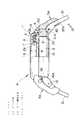
図1は本発明に係る時計用バンドの取付構造を備えた腕時計の一部断面にした側面図、図2は同時計用バンドの取付構造の実施例1の分解状態の斜視図、図3はバンドの基部の裏側の斜視図である。なお、図面において、腕時計の9時−3時方向を左右方向、12時−6時方向を前後方向とする。
【0014】
腕時計Aは時計ケース1を有しており、この時計ケース1は胴2とベゼル3とガラス縁部材4とから構成してある。そして、胴2内にはモジュール5が収容してあり、また、胴2の上側開口部2a側には風防ガラス6がパッキン7を介して嵌着してあり、また、胴2の上面部には、パッキン7の抜けを防止するガラス縁部材4が装着してある。そして、風防ガラス6の下方には時刻を表示する文字盤(表示パネル)8がモジュール5の上面に位置させて設けてあり、胴2の下側開口部2b側に裏蓋10が4本のネジにより取付けてある。
【0015】
胴2の外周部の前後にはバンド取付部14が形成してある。これらのバンド取付部14は、上部ケース側係止部15と下部ケース側係止部16とを有している。そして、上部ケース側係止部15は、胴2の外周部に上向きに突出した突起部9からなり、この上部ケース側係止部15には左右方向に上部係止孔17が形成してある。また、下部ケース側係止部16は、斜め下方に向かって突出する前後一対のツノ足(突起部)16Aからなり、ツノ足16Aには左右方向に下部係止孔18が形成してある。
【0016】
したがって、上部ケース側係止部15の上部係止孔17の位置は、下部ケース側係止部16の下部係止孔18の位置より上方にあり、また、上部ケース側係止部16の上部係止孔17の位置と、下部ケース側係止部16の下部係止孔18の位置とは、平面視で時計ケース1の中心からの距離が異なり、時計ケース1の中心から下部係止孔18までの距離が、時計ケース1の中心から上部係止孔17までの距離より長くなっている。
【0017】
バンド20はウレタン等の合成樹脂で製作してあり、図3に示すように、その基部20Aの端縁部には、ベゼル3の外周面に密接(当接)する円弧状の密接面20cが形成してあり、また、基部20Aの裏面には、上部バンド側係止部21と下部バンド側係止部22とが形成してある。
【0018】
上部バンド側係止部21は、バンド短手方向に互いに離れた一対の突起部23を有しており、これらの突起部23には、バンド短手方向に上部係止孔24が形成してあり、また、突起部23が密接面20cに隣接して、突起部23間には挿入凹部23Aが形成してあり、この挿入凹部23Aは上部ケース側係止部15の円弧状の外面(突起部9の外面)が摺接するように曲面にしてある。
【0019】
下部バンド側係止部22はバンド短手方向に長い突起部25を有しており、この突起部25にはバンド短手方向に下部係止孔26が形成してあって、この突起部25は密接面20cよりバンド長手方向に僅かに離れた位置にあり、上部係止孔24と下部係止孔26との間の距離は、上部ケース側係止部15の上部係止孔17と下部ケース側係止部16の下部係止孔18との間の距離に等しくしてある。また、突起部25のバンド短手方向の寸法は、下部ケース側係止部16の一対のツノ足(突起部)16A間の寸法よりやや小さくしてある。また、上部バンド側係止部21の一対の突起部23にそれぞれ形成された上部係止孔24は、バンド20の側面20aに形成された段付きピン孔27に連通している。
【0020】
そして、バンド20の下部バンド側係止部22の下部係止孔26にバネ棒28を挿入し、この下部バンド側係止部22の突起部25を下部ケース側係止部16の一対のツノ足(突起部)16A間に挿入して、バネ棒28の両端のピボット28Aをツノ足16Aの下部係止孔18に係止する。そして、バンド20の上部バンド側係止部21の一対の突起部23間の挿入凹部23Aに上部ケース側係止部15の突起部9を挿入して上部係止孔17、24同士を一致させる。この状態で、上部係止孔17、24に割りパイプ29を挿入し、バンド20の側面20aの段付きピン孔27に頭付きピン30を両側より挿入して、これらの頭付きピン30の軸部30aを割りパイプ29の端部に圧入して、バンド20がバンド取付部14に取り付けてある。
【0021】
この場合、バンド20の基部20Aの密接面20cはベゼル3の外周面に密接し、上部ケース側係止部15の円弧状の外面が挿入凹部23Aに密接し、ツノ足16Aの外面がバンド20の基部20Aの裏面のツノ足密接面部分20dに密接する。この場合、下部バンド側係止部22の突起部25は裏蓋10に干渉しないために、裏蓋10の外し操作はバンド20を外すことなく行うことができる。
【0022】
腕時計Aを腕に装着した場合に、バンド20には、図1に示す矢印の方向(内方)に力が加えられてバンド20が引っ張られる。しかし、バンド20は、取付位置の異なる2本の係止部材、すなわち、割りパイプ29とバネ棒28とによりバンド取付部14に取り付けてあるために、バンド20の基部20Aは引張力に影響を受けず、このバンド20の基部20Aの密接面20cとベゼル3の外周面との間には隙間は生じない。このために、外観品質の低下がない。
【0023】
(実施例2)
本発明に係る時計用バンドの取付構造の実施例2を図4乃至図6に示す。
図4は本発明に係る時計用バンドの取付構造を備えた腕時計の一部断面にした側面図、図5は同時計用バンドの取付構造の実施例2の分解状態の斜視図、図6はバンドの基部とカバー部材の裏側から見た斜視図である。
【0024】
時計用バンドの取付構造の実施例2が上記した時計用バンドの取付構造の実施例1と異なるのは、そのバンドの構成とカバー部材を追加したことであり、時計ケース1の胴2の外周部に設けられたバンド取付部14は同じであるので、このバンド取付部14は、同じ符号を付して説明を省略する。
【0025】
バンド31は皮製であって、下部ケース側係止部16の一対のツノ足(突起部)16A間に入る幅寸法を有しており、このバンド31の基部31Aにはバンド短手方向に係止孔32が形成してあり、この基部31Aの裏面には係止孔32よりバンド長手方向に所定の距離おいて段部33が形成してある。
【0026】
また、カバー部材34はウレタン等の合成樹脂で製作してあり、その裏面の一方の端縁部34cには、ベゼル3の外周面に密接(当接)する円弧状の密接面35が形成してあり、また、裏面には、カバ−側係止部36とバンド通し部37とが形成してある。
【0027】
このカバ−側係止部36は、バンド短手方向に互いに離れた一対の突起部38を有しており、これらの突起部38には、幅方向(バンド短手方向)に係止孔39が形成してあり、また、突起部38が密接面35に隣接していて、突起部38間には挿入凹部40が形成してあり、この挿入凹部40は上部ケース側係止部15の円弧状の外面が摺接するように曲面にしてある。また、係止孔39は、カバー部材34の側面34aに形成された段付きピン孔41に連通している。
【0028】
また、バンド通し部37は、カバー部材34の他方の端縁部34b側で、カバー部材34の側面34aに一体に形成してあり、バンド通し部37とカバー部材34の側面34aとを含めてバンドガイド37Aを形成している。
【0029】
そして、バンド31の係止孔32にバネ棒42を挿入し、このバンド31の基部31Aを下部ケース側係止部16の一対のツノ足(突起部)16A間に挿入して、バネ棒42の両端のピボット42Aをツノ足16Aの下部係止孔18に係止して、バンド31がバンド取付部14に取り付けてある。
【0030】
そして、バンド31の先側をカバー部材34の裏側からバンドガイド37Aに通して、このカバー部材34をバンド31の基部31A側に移動し、カバー側係止部36の挿入凹部40に上部ケース側係止部15の突起部9を挿入して、上部係止孔17に係止孔39を一致させる。この状態で、上部係止孔17及び係止孔39に割りパイプ43を挿入し、カバー部材34の側面34aに形成された段付きピン孔41に頭付きピン44を挿入して、これらの頭付きピン44の軸部44aを割りパイプ43の端部に圧入して、カバー部材34がバンド取付部14に取り付けてある。
【0031】
この場合、カバー部材34の密接面35はベゼル3の外周面に密接し、上部ケース側係止部15の突起部9の円弧状の外面が挿入凹部40に密接する。そして、この場合、バンド31の基部31Aは裏蓋10に干渉していないために、裏蓋10の外し操作はバンド31を外すことなく行うことができる。
【0032】
上記したように、皮製の普通のバンド31であっても、このバンド31をカバー部材34の裏側からバンドガイド37Aに通して、カバー部材34で包持することにより、上記した時計ケース1のバンド取付部14に取り付けることができる。この場合、カバー部材34はバンド31に働く力を受けないために、このカバー部材34の密接面35とベゼル3の外周面との間には隙間は生じない。このために、外観品質の低下がない。
【0033】
なお、上記した実施例1、2では上部ケース側係止部15を1つの突起部9で構成し、下部ケース側係止部16を一対のツノ足16Aで構成したが、上部ケース側係止部15を2つの突起部で構成し、下部ケース側係止部16を1つのツノ足で構成してもよいし、係止部材としては、バネ棒28、42及び割りパイプ29、43に限らず、ピン、ヘアーピンを使用してもよい。
【0034】
【発明の効果】
本発明によれば、腕時計を腕に装着した場合に、バンドには内方に力が加えられてバンドが引っ張られるが、バンドは、取付位置の異なる2本の係止部材によりバンド取付部に取り付けてあるために、バンドの基部は引張力に影響を受けず、このバンドの基端部と時計ケースの外周面との間には隙間は生じることがなく、外観品質を損なうことがなくなる。
【0035】
また、皮製の普通のバンドであっても、このバンドをカバー部材のバンドガイドに通して、カバー部材で包持することにより、時計ケースのバンド取付部に取り付けることができるし、また、カバー部材はバンドに働く引張力を受けないために、このカバー部材と時計ケースとの間には隙間は生じることがなく、外観品質を損なうことがなくなる。
【0036】
また、バンドを外すことなく、電池交換、モジュールの修理などを行うことができて、作業性を良くすることができる。
【図面の簡単な説明】
【図1】本発明に係る時計用バンドの取付構造(実施例1)を備えた腕時計の一部断面にした側面図である。
【図2】同時計用バンドの取付構造の実施例1の分解状態の斜視図である。
【図3】バンドの基部の裏側の斜視図である。
【図4】本発明に係る時計用バンドの取付構造(実施例2)を備えた腕時計の一部断面にした側面図である。
【図5】同時計用バンドの取付構造の実施例2の分解状態の斜視図である。
【図6】バンドの基部とカバー部材の裏側から見た斜視図である。
【図7】従来の時計用バンドの取付構造の断面図である。
【図8】従来のバンドの基部の斜視図である。
【符号の説明】
1 時計ケース
14 バンド取付部
15 上部ケース側係止部
16 下部ケース側係止部
20 バンド
21 上部バンド側係止部
22 下部バンド側係止部
31 バンド
34 カバー部材
36 カバー側係止部
37A バンドガイド[0001]
BACKGROUND OF THE INVENTION
The present invention relates to a watch band mounting structure in which a band is attached to a band mounting portion provided at opposite positions on both sides of a watch case.
[0002]
[Prior art]
As a conventional structure for attaching this type of watch band, there is a technique disclosed in Japanese Utility Model Laid-Open No. 55-157417. As shown in FIG. 7, the watch band mounting structure includes a
[0003]
Then, in a state where the
[0004]
[Problems to be solved by the invention]
In the conventional watch band mounting structure described above, when a wristwatch is worn on the wrist, if a strong force (inward force) is applied to the
[0005]
The present invention has been made paying attention to such conventional problems, and the purpose of the present invention is that even if a strong force is applied to the band, it is difficult to form a gap between the watch case and the band, Further, it is an object of the present invention to provide a watch band mounting structure that can be attached to a leather band and can be removed without removing the band in the same manner as a normal back cover.
[0006]
[Means for Solving the Problems]
In order to achieve the above object, the present invention relates to a watch band mounting structure in which a band is attached to a band mounting portion provided at opposite positions on both sides of a watch case, and the band mounting portion is connected to the upper case side. Theupper case side locking portion and the lower case side locking portion are formed with a locking hole, and the lower case side locking portion has a locking hole. The distance from the center of the watch case is longer than the locking hole of the upper case side locking portion, and the locking hole of the upper case side locking portion is longer than the locking hole of the lower case side locking portion. The upper band side locking portion and the lower band side locking portion are provided on theband , and theupper band side locking portion and the lower band side locking portion have locking holes. formanda locking hole of the upper band side lockingportion, the upper case side engagementInsert the locking member in the state of being matched locking holes of parts, also,
By locking the locking hole of the lower case side locking portion with the locking member inserted into the locking hole of the lower band side locking portion, the watch case and the band are kept in close contact with each other. It is characterized by that.
[0007]
With this configuration, when the wristwatch is worn on the wrist, the band is pulled inward by applying an inward force to the band, but the band has the upper band side locking portion as the upper case side locking portion and the lower band. The side locking portion is attached to the lower case side locking portion by the locking member, and the watch case and the base end portion of the band are held in close contact with each other, that is, two with different mounting positions The base of the band is not affected by the tensile force, and there is a gap between the base end of the band and the outer peripheral surface of the watch case. And appearance quality is not impaired. In addition, battery replacement, module repair, and the like can be performed without removing the band, and workability can be improved.
[0008]
In order to achieve the above object, the present invention provides a watch band mounting structure in which a band is attached to a band mounting portion provided at opposite positions on both sides of a watch case, and the band mounting portion is disposed on the upper case. It is composed of a side locking portion and a lower case side locking portion, and a lockinghole is formed in the upper case side locking portion and the lower case side locking portion to lock the lower case side locking portion. The hole has a longer distance from the center of the watch case than the locking hole of the upper case side locking portion, and the locking hole of the upper case side locking portion locks the lower case side locking portion. Acover-side engagement portion is provided on a cover member having a band guide thatis provided so as to be positioned above the hole, and has a band guide through which the band is inserted.A locking hole is formed on the base and inserted into the locking hole at the base of the band.Alocking hole of the lower case side engagement portionwith the locking memberengagedwiththebandthrough the band guidealso includes a locking hole of the cover-side engaging portion, the upper case side engagement The locking member is inserted in astate in which the locking holes of the portions are matched .
[0009]
With this configuration, even a normal leather band can be attached to the band mounting portion of the watch case by passing the band through the band guide of the cover member and holding it with the cover member. Since the cover member does not receive the tensile force acting on the band, there is no gap between the cover member and the watch case, and the appearance quality is not impaired. Furthermore, since the band guide restricts the direction of the leading end of the band, the band can be attached to the wrist remarkably. In addition, battery replacement, module repair, and the like can be performed without removing the band, and workability can be improved.
[0010]
The upper case side locking portion and the lower case side locking portion may each have a different band mounting structure, and the upper case side locking portion and the lower case side locking portion may be different from each other. Are provided at different distances from the watch case in the planar state. With such a configuration, the design variation of the band mounting portion can be expanded. Further, there is no gap between the watch case and the base end portion of the band, and the leather band can be attached to the watch case without a sense of incongruity.
[0011]
Further, at least one of the upper case side locking portion and the lower case side locking portion may be covered with the band, or the upper case side locking portion may be covered with the cover member. . With this configuration, when the watch is viewed in plan, the two band mounting portions are not visible, so there is no sense of incongruity, the appearance quality similar to that of a general watch is obtained, and the design variation can be expanded. . The locking member may be at least one of a spring bar, a pin, a split pipe, and a hair pin.
[0012]
DETAILED DESCRIPTION OF THE INVENTION
Embodiments of the present invention will be described below with reference to the drawings.
[0013]
Example 1
A first embodiment of a watch band mounting structure according to the present invention is shown in FIGS.
FIG. 1 is a side view, partly in section, of a wristwatch equipped with a watch band mounting structure according to the present invention, FIG. 2 is an exploded perspective view of
[0014]
The watch A has a
[0015]
[0016]
Therefore, the position of the
[0017]
The
[0018]
The upper band
[0019]
The lower band
[0020]
Then, a
[0021]
In this case, the
[0022]
When the wristwatch A is worn on the wrist, a force is applied to the
[0023]
(Example 2)
A second embodiment of the watch band mounting structure according to the present invention is shown in FIGS.
4 is a side view, partly in section, of a wristwatch having a watch band mounting structure according to the present invention, FIG. 5 is an exploded perspective view of
[0024]
Example 2 of the watch band mounting structure differs from Example 1 of the watch band mounting structure described above in that the configuration of the band and a cover member are added, and the outer periphery of the
[0025]
The
[0026]
The
[0027]
The cover
[0028]
The banding
[0029]
Then, a
[0030]
Then, the front side of the
[0031]
In this case, the
[0032]
As described above, even if it is a
[0033]
In the first and second embodiments described above, the upper case
[0034]
【The invention's effect】
According to the present invention, when the wristwatch is worn on the wrist, the band is pulled inward by applying an inward force to the band. The band is attached to the band mounting portion by the two locking members having different mounting positions. Since it is attached, the base of the band is not affected by the tensile force, and there is no gap between the base end of the band and the outer peripheral surface of the watch case, and the appearance quality is not impaired.
[0035]
Moreover, even if it is a normal leather band, it can be attached to the band mounting part of the watch case by passing this band through the band guide of the cover member and holding it with the cover member. Since the member does not receive the tensile force acting on the band, there is no gap between the cover member and the watch case, and the appearance quality is not impaired.
[0036]
In addition, battery replacement, module repair, and the like can be performed without removing the band, and workability can be improved.
[Brief description of the drawings]
FIG. 1 is a side view, partly in section, of a wristwatch provided with a watch band mounting structure (Example 1) according to the present invention.
FIG. 2 is a perspective view of an exploded state of the first embodiment of the watch band mounting structure.
FIG. 3 is a perspective view of the back side of the base of the band.
FIG. 4 is a side view, partly in section, of a wristwatch provided with a watch band mounting structure according to the present invention (Example 2).
FIG. 5 is a perspective view of an exploded state of the second embodiment of the watch band mounting structure.
FIG. 6 is a perspective view of the base of the band and the back side of the cover member.
FIG. 7 is a cross-sectional view of a conventional watch band mounting structure.
FIG. 8 is a perspective view of a base portion of a conventional band.
[Explanation of symbols]
DESCRIPTION OF
Claims (4)
Translated fromJapanese前記バンド取付部を上部ケース側係止部と下部ケース側係止部とで構成し、
前記上部ケース側係止部、前記下部ケース側係止部には係止孔を形成し、
前記下部ケース側係止部の係止孔は、前記上部ケース側係止部の係止孔より時計ケースの中心からの距離が長く、かつ、
前記上部ケース側係止部の係止孔は、前記下部ケース側係止部の係止孔より上方に位置するように設け、また、
前記バンドに上部バンド側係止部と下部バンド側係止部とを設け、
前記上部バンド側係止部、前記下部バンド側係止部には係止孔を形成し、
前記上部バンド側係止部の係止孔と、前記上部ケース側係止部の係止孔を一致させた状態で係止部材を挿入し、また、
前記下部バンド側係止部の係止孔に挿入した係止部材で前記下部ケース側係止部の係止孔を係止することで、
前記時計ケースと前記バンドとの密接状態を保持するようにしたことを特徴とする時計用バンドの取付構造。In the watch band mounting structure for attaching the band to the band mounting portion provided at the opposite position on both sides of the watch case,
The band mounting portion is composed of an upper case side locking portion and a lower case side locking portion,
A locking hole is formed in the upper case side locking portion and the lower case side locking portion,
The locking hole of the lower case side locking portion has a longer distance from the center of the watch case than the locking hole of the upper case side locking portion, and
The locking hole of the upper case side locking portion is provided to be positioned above the locking hole of the lower case side locking portion,
The band is provided with an upper band side locking part and a lower band side locking part,
A locking hole is formed in the upper band side locking portion and the lower band side locking portion,
Insert the locking member in a state where the locking hole of the upper band side locking portion andthe locking hole of the upper case side locking portionare aligned,
By locking the locking hole of the lower case side locking portion with the locking member inserted into the locking hole of the lower band side locking portion,
A watch band mounting structure characterized in that the watch case and the band are kept in close contact with each other.
前記バンド取付部を上部ケース側係止部と下部ケース側係止部とで構成し、
前記上部ケース側係止部、前記下部ケース側係止部には係止孔を形成し、
前記下部ケース側係止部の係止孔は、前記上部ケース側係止部の係止孔より時計ケースの中心からの距離が長く、かつ、
前記上部ケース側係止部の係止孔は、前記下部ケース側係止部の係止孔より上方に位置するように設け、また、
前記バンドの基部に係止孔を形成し、
前記バンドを挿通するバンドガイドを有するカバー部材にカバー側係止部を設け、
前記カバー側係止部に係止孔を形成し、
前記バンドの基部の係止孔に挿入した係止部材で前記下部ケース側係止部の係止孔を係止し、
前記バンドは前記バンドガイドに通し、また、
前記カバー側係止部の係止孔と、前記上部ケース側係止部の係止孔を一致させた状態で係止部材を挿入した
ことを特徴とする時計用バンドの取付構造。In the watch band mounting structure for attaching the band to the band mounting portion provided at the opposite position on both sides of the watch case,
The band mounting portion is composed of an upper case side locking portion and a lower case side locking portion,
A lockinghole is formed in the upper case side locking portionand the lower case side locking portion,
The locking hole of the lower case side locking portion has a longer distance from the center of the watch case than the locking hole of the upper case side locking portion, and
The locking hole of the upper case side locking portion is provided to be positioned above the locking hole of the lower case side locking portion,
Forming a locking hole in the base of the band;
The cover member having a band guide for inserting the band is provided with acover side locking portion,
Forming a locking hole in the cover side locking portion;
Locking the locking hole of the lower case side locking portion with a locking member inserted into the locking hole of the base of the band,
The band passes through the band guide, and
An attachment structure for a watch band, wherein a locking member is inserted in astate in which a locking hole of the cover side locking portion is aligned with a locking hole of the upper case side locking portion .
Priority Applications (5)
| Application Number | Priority Date | Filing Date | Title |
|---|---|---|---|
| JP07255497AJP3964492B2 (en) | 1997-03-26 | 1997-03-26 | Watch band mounting structure |
| PCT/JP1998/001329WO1998042227A1 (en) | 1997-03-26 | 1998-03-25 | Wrist watch |
| CN 98800327CN1220585A (en) | 1997-03-26 | 1998-03-25 | Wrist watch |
| EP98911001AEP0945083A4 (en) | 1997-03-26 | 1998-03-25 | Wrist watch |
| TW087104540ATW362961B (en) | 1997-03-26 | 1998-03-26 | A mounting device for wrist watch band |
Applications Claiming Priority (1)
| Application Number | Priority Date | Filing Date | Title |
|---|---|---|---|
| JP07255497AJP3964492B2 (en) | 1997-03-26 | 1997-03-26 | Watch band mounting structure |
Publications (2)
| Publication Number | Publication Date |
|---|---|
| JPH10262710A JPH10262710A (en) | 1998-10-06 |
| JP3964492B2true JP3964492B2 (en) | 2007-08-22 |
Family
ID=13492701
Family Applications (1)
| Application Number | Title | Priority Date | Filing Date |
|---|---|---|---|
| JP07255497AExpired - LifetimeJP3964492B2 (en) | 1997-03-26 | 1997-03-26 | Watch band mounting structure |
Country Status (5)
| Country | Link |
|---|---|
| EP (1) | EP0945083A4 (en) |
| JP (1) | JP3964492B2 (en) |
| CN (1) | CN1220585A (en) |
| TW (1) | TW362961B (en) |
| WO (1) | WO1998042227A1 (en) |
Families Citing this family (7)
| Publication number | Priority date | Publication date | Assignee | Title |
|---|---|---|---|---|
| BR0016875A (en) | 1999-12-29 | 2003-06-17 | Hill Rom Services Inc | Patient support, patient-configured mattress, patient support method, method of maintaining a patient's heel pressure relief, pressure system for use with a patient support mattress, and patient support frame |
| JP4712385B2 (en) | 2002-09-06 | 2011-06-29 | ヒル−ロム サービシーズ,インコーポレイティド | Hospital bed |
| CN101950153B (en)* | 2010-09-30 | 2012-03-14 | 鸿富锦精密工业(深圳)有限公司 | Wriststrap type electronic device |
| EP2781973B1 (en)* | 2013-03-19 | 2016-01-06 | ETA SA Manufacture Horlogère Suisse | System for attaching a bracelet strand to a case |
| JP6452076B2 (en)* | 2014-05-19 | 2019-01-16 | カシオ計算機株式会社 | Band mounting structure and watch |
| CN107467818A (en)* | 2017-08-26 | 2017-12-15 | 翟云鹏 | Vulcanize rubber watchband |
| ES3003534T3 (en) | 2020-06-16 | 2025-03-10 | Elc Man Llc | Single-piece watch band |
Family Cites Families (8)
| Publication number | Priority date | Publication date | Assignee | Title |
|---|---|---|---|---|
| JPS5424372U (en)* | 1977-07-21 | 1979-02-17 | ||
| JPS5430964U (en)* | 1977-08-03 | 1979-02-28 | ||
| JPS5877514U (en)* | 1981-11-24 | 1983-05-25 | セイコーエプソン株式会社 | Band fitting device |
| JPS5955012U (en)* | 1982-10-01 | 1984-04-11 | シチズン時計株式会社 | Watch case and band attachment device |
| US4785982A (en)* | 1986-02-21 | 1988-11-22 | Citizen Watch Co., Ltd. | Watch case and band attachment structure |
| JPS6428114U (en)* | 1987-08-11 | 1989-02-17 | ||
| EP0595774B1 (en)* | 1992-10-29 | 1997-06-25 | Firma H. Finger | Means for fastening a watch crystal to a bezel |
| JPH08238116A (en)* | 1995-03-07 | 1996-09-17 | Casio Comput Co Ltd | Band mounting structure |
- 1997
- 1997-03-26JPJP07255497Apatent/JP3964492B2/ennot_activeExpired - Lifetime
- 1998
- 1998-03-25CNCN 98800327patent/CN1220585A/enactivePending
- 1998-03-25WOPCT/JP1998/001329patent/WO1998042227A1/ennot_activeApplication Discontinuation
- 1998-03-25EPEP98911001Apatent/EP0945083A4/ennot_activeWithdrawn
- 1998-03-26TWTW087104540Apatent/TW362961B/enactive
Also Published As
| Publication number | Publication date |
|---|---|
| WO1998042227A1 (en) | 1998-10-01 |
| EP0945083A1 (en) | 1999-09-29 |
| EP0945083A4 (en) | 2000-05-24 |
| TW362961B (en) | 1999-07-01 |
| JPH10262710A (en) | 1998-10-06 |
| CN1220585A (en) | 1999-06-23 |
Similar Documents
| Publication | Publication Date | Title |
|---|---|---|
| US6435709B2 (en) | Band and wrist device | |
| US5668784A (en) | Watch band attachment mechanism | |
| CA2552424C (en) | Link element including a casing formed of a plate and a back plate | |
| KR100538118B1 (en) | Intermediate clasp for band type ornaments | |
| KR100523657B1 (en) | Device for attaching a bracelet to a watchcase | |
| CN206880231U (en) | belt and watch | |
| US4605312A (en) | Watchband/watchcase connection | |
| JP3964492B2 (en) | Watch band mounting structure | |
| JP2004324294A (en) | Inside door handle device of automobile | |
| JPH04213093A (en) | Bracelet and strand attaching device for side plate of time piece | |
| JP2002240603A (en) | Vehicle seat | |
| CN111736446A (en) | clock | |
| JP2007090046A (en) | Arm wearing device | |
| JP2003329782A (en) | Connecting structure between watch and band | |
| JP2789428B2 (en) | Magnet mounting structure and towel hook using the mounting structure | |
| JPH0210505Y2 (en) | ||
| JP2004144536A (en) | Band mounting structure | |
| KR19980010421U (en) | Inner fastening device of glasses case | |
| KR970001951Y1 (en) | Wristwatches with detachable accessories | |
| JPH0641518U (en) | Watch band | |
| JPH11127921A (en) | Connecting mechanism for watchband and case | |
| HK1013447B (en) | Watch band attachment mechanism | |
| JP3093126U (en) | Bracelet or wristband | |
| JPH11133159A (en) | Portable electronic apparatus with soft cover | |
| JP2005070002A (en) | Fixing structure of exterior member in wristwatch |
Legal Events
| Date | Code | Title | Description |
|---|---|---|---|
| A131 | Notification of reasons for refusal | Free format text:JAPANESE INTERMEDIATE CODE: A131 Effective date:20060725 | |
| A521 | Written amendment | Free format text:JAPANESE INTERMEDIATE CODE: A523 Effective date:20060912 | |
| A131 | Notification of reasons for refusal | Free format text:JAPANESE INTERMEDIATE CODE: A131 Effective date:20070306 | |
| A521 | Written amendment | Free format text:JAPANESE INTERMEDIATE CODE: A523 Effective date:20070419 | |
| RD03 | Notification of appointment of power of attorney | Free format text:JAPANESE INTERMEDIATE CODE: A7423 Effective date:20070419 | |
| TRDD | Decision of grant or rejection written | ||
| A01 | Written decision to grant a patent or to grant a registration (utility model) | Free format text:JAPANESE INTERMEDIATE CODE: A01 Effective date:20070522 | |
| A61 | First payment of annual fees (during grant procedure) | Free format text:JAPANESE INTERMEDIATE CODE: A61 Effective date:20070524 | |
| R150 | Certificate of patent or registration of utility model | Free format text:JAPANESE INTERMEDIATE CODE: R150 | |
| FPAY | Renewal fee payment (event date is renewal date of database) | Free format text:PAYMENT UNTIL: 20120601 Year of fee payment:5 | |
| FPAY | Renewal fee payment (event date is renewal date of database) | Free format text:PAYMENT UNTIL: 20140601 Year of fee payment:7 | |
| S533 | Written request for registration of change of name | Free format text:JAPANESE INTERMEDIATE CODE: R313533 | |
| R350 | Written notification of registration of transfer | Free format text:JAPANESE INTERMEDIATE CODE: R350 | |
| EXPY | Cancellation because of completion of term |