JP3962256B2 - Apparatus, sample cuvette, and optical measurement method - Google Patents
Apparatus, sample cuvette, and optical measurement methodDownload PDFInfo
- Publication number
- JP3962256B2 JP3962256B2JP2001554045AJP2001554045AJP3962256B2JP 3962256 B2JP3962256 B2JP 3962256B2JP 2001554045 AJP2001554045 AJP 2001554045AJP 2001554045 AJP2001554045 AJP 2001554045AJP 3962256 B2JP3962256 B2JP 3962256B2
- Authority
- JP
- Japan
- Prior art keywords
- filter
- sample
- light
- absorbance
- cuvette
- Prior art date
- Legal status (The legal status is an assumption and is not a legal conclusion. Google has not performed a legal analysis and makes no representation as to the accuracy of the status listed.)
- Expired - Fee Related
Links
- 230000003287optical effectEffects0.000titleclaimsabstractdescription78
- 238000000691measurement methodMethods0.000titleclaims3
- 238000005259measurementMethods0.000claimsabstractdescription49
- 238000000034methodMethods0.000claimsabstractdescription44
- 210000004369bloodAnatomy0.000claimsabstractdescription38
- 239000008280bloodSubstances0.000claimsabstractdescription38
- 238000002835absorbanceMethods0.000claimsdescription106
- 238000010521absorption reactionMethods0.000claimsdescription73
- 238000001514detection methodMethods0.000claimsdescription40
- 108010054147HemoglobinsProteins0.000claimsdescription37
- 102000001554HemoglobinsHuman genes0.000claimsdescription37
- 230000007423decreaseEffects0.000claimsdescription16
- 238000000149argon plasma sinteringMethods0.000claimsdescription15
- 230000035945sensitivityEffects0.000claimsdescription13
- BPYKTIZUTYGOLE-IFADSCNNSA-NBilirubinChemical compoundN1C(=O)C(C)=C(C=C)\C1=C\C1=C(C)C(CCC(O)=O)=C(CC2=C(C(C)=C(\C=C/3C(=C(C=C)C(=O)N\3)C)N2)CCC(O)=O)N1BPYKTIZUTYGOLE-IFADSCNNSA-N0.000claimsdescription12
- PEDCQBHIVMGVHV-UHFFFAOYSA-NGlycerineChemical compoundOCC(O)COPEDCQBHIVMGVHV-UHFFFAOYSA-N0.000claimsdescription12
- 230000008878couplingEffects0.000claimsdescription12
- 238000010168coupling processMethods0.000claimsdescription12
- 238000005859coupling reactionMethods0.000claimsdescription12
- 150000001875compoundsChemical class0.000claimsdescription8
- INGWEZCOABYORO-UHFFFAOYSA-N2-(furan-2-yl)-7-methyl-1h-1,8-naphthyridin-4-oneChemical compoundN=1C2=NC(C)=CC=C2C(O)=CC=1C1=CC=CO1INGWEZCOABYORO-UHFFFAOYSA-N0.000claimsdescription7
- 108010064719OxyhemoglobinsProteins0.000claimsdescription7
- 108010002255deoxyhemoglobinProteins0.000claimsdescription7
- UGFAIRIUMAVXCW-UHFFFAOYSA-NCarbon monoxideChemical compound[O+]#[C-]UGFAIRIUMAVXCW-UHFFFAOYSA-N0.000claimsdescription6
- 108010061951MethemoglobinProteins0.000claimsdescription6
- 108010016811SulfhemoglobinProteins0.000claimsdescription6
- QVGXLLKOCUKJST-UHFFFAOYSA-Natomic oxygenChemical compound[O]QVGXLLKOCUKJST-UHFFFAOYSA-N0.000claimsdescription6
- 229910002091carbon monoxideInorganic materials0.000claimsdescription6
- 229910052760oxygenInorganic materials0.000claimsdescription6
- 239000001301oxygenSubstances0.000claimsdescription6
- 229910052751metalInorganic materials0.000claimsdescription4
- 239000002184metalSubstances0.000claimsdescription4
- NIXOWILDQLNWCW-UHFFFAOYSA-MAcrylateChemical compound[O-]C(=O)C=CNIXOWILDQLNWCW-UHFFFAOYSA-M0.000claimsdescription3
- 229910044991metal oxideInorganic materials0.000claimsdescription3
- 150000004706metal oxidesChemical class0.000claimsdescription3
- 229920001296polysiloxanePolymers0.000claimsdescription3
- 239000002861polymer materialSubstances0.000claims2
- 239000000126substanceSubstances0.000abstractdescription4
- 239000013598vectorSubstances0.000description11
- 210000000601blood cellAnatomy0.000description9
- 230000005540biological transmissionEffects0.000description7
- 230000008859changeEffects0.000description7
- 238000010586diagramMethods0.000description6
- 238000002474experimental methodMethods0.000description6
- 230000002776aggregationEffects0.000description5
- 239000010410layerSubstances0.000description5
- 238000004220aggregationMethods0.000description4
- 230000001419dependent effectEffects0.000description4
- 230000000694effectsEffects0.000description4
- 238000005516engineering processMethods0.000description4
- 239000011888foilSubstances0.000description4
- 239000000463materialSubstances0.000description4
- 229920000642polymerPolymers0.000description4
- 230000005855radiationEffects0.000description4
- 230000015572biosynthetic processEffects0.000description3
- 230000000052comparative effectEffects0.000description3
- 238000012937correctionMethods0.000description3
- 230000003247decreasing effectEffects0.000description3
- 239000000975dyeSubstances0.000description3
- 239000011521glassSubstances0.000description3
- 238000001556precipitationMethods0.000description3
- XUIMIQQOPSSXEZ-UHFFFAOYSA-NSiliconChemical group[Si]XUIMIQQOPSSXEZ-UHFFFAOYSA-N0.000description2
- BQCADISMDOOEFD-UHFFFAOYSA-NSilverChemical compound[Ag]BQCADISMDOOEFD-UHFFFAOYSA-N0.000description2
- 230000002159abnormal effectEffects0.000description2
- 230000001747exhibiting effectEffects0.000description2
- 239000007788liquidSubstances0.000description2
- 238000013507mappingMethods0.000description2
- 229920000728polyesterPolymers0.000description2
- 238000012545processingMethods0.000description2
- 229910052710siliconInorganic materials0.000description2
- 239000010703siliconSubstances0.000description2
- 229910052709silverInorganic materials0.000description2
- 239000004332silverSubstances0.000description2
- 238000004611spectroscopical analysisMethods0.000description2
- 238000002834transmittanceMethods0.000description2
- 239000004925Acrylic resinSubstances0.000description1
- WQZGKKKJIJFFOK-GASJEMHNSA-NGlucoseNatural productsOC[C@H]1OC(O)[C@H](O)[C@@H](O)[C@@H]1OWQZGKKKJIJFFOK-GASJEMHNSA-N0.000description1
- DGAQECJNVWCQMB-PUAWFVPOSA-MIlexoside XXIXChemical compoundC[C@@H]1CC[C@@]2(CC[C@@]3(C(=CC[C@H]4[C@]3(CC[C@@H]5[C@@]4(CC[C@@H](C5(C)C)OS(=O)(=O)[O-])C)C)[C@@H]2[C@]1(C)O)C)C(=O)O[C@H]6[C@@H]([C@H]([C@@H]([C@H](O6)CO)O)O)O.[Na+]DGAQECJNVWCQMB-PUAWFVPOSA-M0.000description1
- 230000002411adverseEffects0.000description1
- 238000005054agglomerationMethods0.000description1
- 230000008033biological extinctionEffects0.000description1
- 239000003795chemical substances by applicationSubstances0.000description1
- 230000008602contractionEffects0.000description1
- 230000023077detection of light stimulusEffects0.000description1
- 239000003792electrolyteSubstances0.000description1
- 210000003743erythrocyteAnatomy0.000description1
- 238000001914filtrationMethods0.000description1
- 239000008103glucoseSubstances0.000description1
- 238000005534hematocritMethods0.000description1
- 238000003384imaging methodMethods0.000description1
- 210000000265leukocyteAnatomy0.000description1
- 230000031700light absorptionEffects0.000description1
- 150000002632lipidsChemical class0.000description1
- 239000008267milkSubstances0.000description1
- 210000004080milkAnatomy0.000description1
- 235000013336milkNutrition0.000description1
- 239000013307optical fiberSubstances0.000description1
- 230000003204osmotic effectEffects0.000description1
- 230000003647oxidationEffects0.000description1
- 238000007254oxidation reactionMethods0.000description1
- 239000003973paintSubstances0.000description1
- 239000002245particleSubstances0.000description1
- 230000035515penetrationEffects0.000description1
- 230000002093peripheral effectEffects0.000description1
- 238000005375photometryMethods0.000description1
- 230000008569processEffects0.000description1
- 102000004169proteins and genesHuman genes0.000description1
- 108090000623proteins and genesProteins0.000description1
- 238000000926separation methodMethods0.000description1
- 208000007056sickle cell anemiaDiseases0.000description1
- 229920002545silicone oilPolymers0.000description1
- 229920002050silicone resinPolymers0.000description1
- 239000002356single layerSubstances0.000description1
- 229910052708sodiumInorganic materials0.000description1
- 239000011734sodiumSubstances0.000description1
- 238000012306spectroscopic techniqueMethods0.000description1
- 238000001228spectrumMethods0.000description1
- 238000004544sputter depositionMethods0.000description1
- 239000002351wastewaterSubstances0.000description1
- XLYOFNOQVPJJNP-UHFFFAOYSA-NwaterSubstancesOXLYOFNOQVPJJNP-UHFFFAOYSA-N0.000description1
- 239000003643water by typeSubstances0.000description1
Images


Classifications
- G—PHYSICS
- G01—MEASURING; TESTING
- G01N—INVESTIGATING OR ANALYSING MATERIALS BY DETERMINING THEIR CHEMICAL OR PHYSICAL PROPERTIES
- G01N21/00—Investigating or analysing materials by the use of optical means, i.e. using sub-millimetre waves, infrared, visible or ultraviolet light
- G01N21/01—Arrangements or apparatus for facilitating the optical investigation
- G01N21/03—Cuvette constructions
- G01N21/05—Flow-through cuvettes
- G—PHYSICS
- G01—MEASURING; TESTING
- G01N—INVESTIGATING OR ANALYSING MATERIALS BY DETERMINING THEIR CHEMICAL OR PHYSICAL PROPERTIES
- G01N21/00—Investigating or analysing materials by the use of optical means, i.e. using sub-millimetre waves, infrared, visible or ultraviolet light
- G01N21/17—Systems in which incident light is modified in accordance with the properties of the material investigated
- G01N21/25—Colour; Spectral properties, i.e. comparison of effect of material on the light at two or more different wavelengths or wavelength bands
- G01N21/31—Investigating relative effect of material at wavelengths characteristic of specific elements or molecules, e.g. atomic absorption spectrometry
- G—PHYSICS
- G01—MEASURING; TESTING
- G01N—INVESTIGATING OR ANALYSING MATERIALS BY DETERMINING THEIR CHEMICAL OR PHYSICAL PROPERTIES
- G01N21/00—Investigating or analysing materials by the use of optical means, i.e. using sub-millimetre waves, infrared, visible or ultraviolet light
- G01N21/17—Systems in which incident light is modified in accordance with the properties of the material investigated
- G01N21/47—Scattering, i.e. diffuse reflection
- G01N21/49—Scattering, i.e. diffuse reflection within a body or fluid
- G01N21/51—Scattering, i.e. diffuse reflection within a body or fluid inside a container, e.g. in an ampoule
- G—PHYSICS
- G01—MEASURING; TESTING
- G01N—INVESTIGATING OR ANALYSING MATERIALS BY DETERMINING THEIR CHEMICAL OR PHYSICAL PROPERTIES
- G01N21/00—Investigating or analysing materials by the use of optical means, i.e. using sub-millimetre waves, infrared, visible or ultraviolet light
- G01N21/01—Arrangements or apparatus for facilitating the optical investigation
- G01N21/03—Cuvette constructions
- G01N2021/0346—Capillary cells; Microcells
- G—PHYSICS
- G01—MEASURING; TESTING
- G01N—INVESTIGATING OR ANALYSING MATERIALS BY DETERMINING THEIR CHEMICAL OR PHYSICAL PROPERTIES
- G01N21/00—Investigating or analysing materials by the use of optical means, i.e. using sub-millimetre waves, infrared, visible or ultraviolet light
- G01N21/17—Systems in which incident light is modified in accordance with the properties of the material investigated
- G01N21/47—Scattering, i.e. diffuse reflection
- G01N21/49—Scattering, i.e. diffuse reflection within a body or fluid
- G01N21/51—Scattering, i.e. diffuse reflection within a body or fluid inside a container, e.g. in an ampoule
- G01N2021/513—Cuvettes for scattering measurements
Landscapes
- Physics & Mathematics (AREA)
- Health & Medical Sciences (AREA)
- Life Sciences & Earth Sciences (AREA)
- Chemical & Material Sciences (AREA)
- Analytical Chemistry (AREA)
- Biochemistry (AREA)
- General Health & Medical Sciences (AREA)
- General Physics & Mathematics (AREA)
- Immunology (AREA)
- Pathology (AREA)
- Spectroscopy & Molecular Physics (AREA)
- Investigating Or Analysing Materials By Optical Means (AREA)
- Measurement Of The Respiration, Hearing Ability, Form, And Blood Characteristics Of Living Organisms (AREA)
- Investigating Or Analysing Biological Materials (AREA)
- Optical Measuring Cells (AREA)
Abstract
Description
Translated fromJapanese【0001】
【発明の属する技術分野】
本発明は、様々なレベルの散乱を示す試料の光学測定を行うための装置、試料キュベット、及び方法に関し、詳細には、全血の試料の光学測定を行うための装置、試料キュベット、及び方法に関する。
【0002】
【従来の技術】
光源から試料を横切る光の透過を検出器によって決定する光学測定は、広範な化学物質及び臨床研究を行うための強力な道具である。理想的な試料については、吸光度は、試料中の吸光種の濃度並びに試料の厚さに比例する。ランバート−ベールの法則はこの関係を以下の式で示す。
A=logI0/I=εcd
ここで、I0及びIは、夫々、入射光及び透過光の強さであり、cは吸収種の濃度であり、dは試料の厚さであり、εは吸光率である。項logI0/Iを吸光度Aと呼ぶ。
【0003】
しかしながら、多くの実際の試料について散乱が生じる。従って、光の透過が様々な方法で邪魔され、これにより計測が困難になり、それらの濃度及び探し求められるパラメータについての正しい値を得るためにこれを補正しなければならない。
【0004】
散乱の一つの主な理由は試料の異質性(inhomogenity)であり、異質試料の粒子との相互作用時に光が散乱するためである。従って、光は直接透過せず、所定の散乱角範囲に亘って屈折する。散乱及び散乱光は円形対称を有し、散乱角αによって特徴付けることができる。
【0005】
散乱角αは、光の中央光路からの散乱光の角度のずれと定義され、散乱角の頂点が試料チャンバの中央と定義される。検出器に到達した光の入射角βは、入射光と検出器表面との間の角度と定義される。散乱角α及び入射角βは、0°乃至90°の角度範囲で散乱した光について、α+β=90°に関係にある。
【0006】
散乱と関連した多くの現象が光学測定を困難にする。かくして、検出器の検出範囲外の角度αでの光の散乱は、光のこの部分を検出に利用できなくしてしまう。更に、多くの検出器は、入射角の小さな光に対する感度が、入射角β=90°の光に対する感度と比較して低い。
【0007】
考えなければならない別の現象は反射である。光の反射は、光路中の任意の光学的界面で生じる。大きな散乱角で散乱した光は、非散乱光又は小さい散乱角で散乱した光と比較して高い反射を示す傾向がある。最後に、散乱により、有効光路長及びかくして吸光度が非散乱光と比較して増大する。
【0008】
散乱係数は、散乱角に対する光の強さの分布であると定義される。かくして、一定量以上の散乱によって支配されるこれらの測定は散乱係数が高く、これに対し散乱が小さい測定は散乱係数が低い。
【0009】
散乱係数が一定である場合には、上述の現象は、計測値のデータ処理工程で容易に補正できる。しかしながら、残念なことに散乱係数は一定でなく、所定範囲の試料パラメータに従って変化する。
【0010】
散乱係数が変化するこの現象は、測定を更に困難にする。かくして、検出器の範囲を越える散乱による影響が及ぼされた測定は、高過ぎる吸収種濃度を誤って表示する。しかしながら、検出されなかった光のレベルを直接的に決定する方法はない。
【0011】
高散乱係数の測定は、入射角が低い光のレベルが高い。このような状態では感度が低いため、検出器は、吸収種の高過ぎる吸収及び高過ぎる濃度を誤って表示する。しかしながら、散乱係数が試料によって異なるため、この現象をデータ処理工程で直ちに補正することはできない。
【0012】
散乱係数が変化する場合には、反射レベルも同様に変化する。散乱係数が高い場合によく起こる、反射が高い場合には、光が一定量以上失なわれ、吸収種の高い濃度が誤って表示される。上文中に説明したように、反射による損失を直ちに決定する方法はない。
【0013】
更に、散乱係数の変化は、上文中に説明したように吸光度に影響を及ぼし、有効光路長を変化させる。散乱係数が高い試料は、吸収種の濃度が高いと誤って表示されるけれども、吸収の増大は、実際には、有効光路長の増大による。有効光路長は試料によって異なり、直ちに決定することはできない。
【0014】
散乱係数の変化による悪影響を受けるこのような試料の重要な例は、全血、即ち溶血しておらず従って高度に異質性の血液である。
全血では、従来、光学的方法によって測定されたパラメータ及び構成要素は、全ヘモグロビン濃度(tHb)、ヘマトクリット値(HCT)、即ち血液の全容積に対する赤血球がある割合、及びグルコース濃度である。オキシヘモグロビン、デオキシヘモグロビン、メトヘモグロビン、一酸化炭素ヘモグロビン、及びスルフヘモグロビン等の特定のヘモグロビン誘導体並びにビリルビン及び診断染料が、光学原理を使用して測定される他の種の例である。
【0015】
全血では、濃度、浸透容積変化、血液細胞の凝集及び形成は、全て、散乱係数に影響を及ぼすパラメータである。
血液細胞の濃度に関し、HCTの代表的範囲が40%乃至50%の試料について最大の散乱が観察される。これよりもHCTが高い又は低い試料は、散乱係数が低い。
【0016】
散乱係数は、更に、平均ヘモグロビン濃度(MCHC)に左右される。平均ヘモグロビン濃度(MCHC)は、(tHb)と(HCT)との間の比(MCHC=tHb/HCT)と定義される。MCHCは、かくして、血液細胞中のヘモグロビンの濃度であり、血液細胞浸透容積変化を理解する上で重要なパラメータである。
【0017】
浸透容積変化は、電解質の濃度変化によって引き起こされるため、散乱係数に影響を及ぼす。濃度が高い場合、例えば塩分濃度が高い場合には、浸透により血液細胞から血漿相への水の流れが生じ、その間、血液細胞が収縮し、散乱が増大する。かくして、二つの血液試料は同様のヘモグロビン濃度であるが、血液細胞の収縮が高い−及びかくしてMCHCが高い−試料は、ヘモグロビン濃度が高いように見える。
【0018】
所与のtHbで、tHbの実験による決定についてのエラーは、MCHCに従って変化するということが観察された。かくして、tHbの代表的レベルである15g/dlでは、実験的に決定されたtHbは、MCHCが±10%変化する際に約±4%変化する。MCHCがこれよりも大きく、例えば±25%変化する場合には、実験的に決定されたtHbは、約±13%変化する。これは、臨床の目的では受け入れられない。例1及び比較例1を参照されたい。
【0019】
散乱係数に影響を及ぼすこの他の現象は、血液細胞の凝集、沈澱、及び鎌状細胞疾患の場合に観察される異常形成である。かくして、凝集及び沈澱が起こると係数が減少し、沈澱していない試料と比較して低過ぎるヘモグロビン濃度を誤って表示する。異常形成も同様に散乱係数を変化させてしまう。
【0020】
特定の脂質及び蛋白質の濃度によって散乱レベルが更に大きく影響されるため、完全な散乱現象及びその変化レベルは非常に複雑である。従って、多くの特許が、測光法や分光法等の光学的方法による血液パラメータの測定の問題点を取り扱ってきた。これらの特許は、二つのグループに分けることができる。第1のグループは、問題点に対して幾何学的解決策を追求し、第2のグループは、多波長技術に基づいて解決策を追求する。第1のグループの他の特許には、血液パラメータを測定するための方法及び装置を開示するカナダ国のマニトバ大学に賦与された欧州特許第EP575712A2号が含まれる。この特許の方法によれば、直接出てくる光及び測光測定された散乱光の変化を一つ又はそれ以上の基準と比較し、例えば血液のナトリウム濃度による光の散乱の変化の効果を考慮する。この方法及び装置によれば、最少で二つの検出手段で光の検出を行う。第1検出手段は直接出てくる光を検出し、第2検出手段及び検出手段が二つ以上設けられている場合のこの他の検出手段が散乱光を検出する。同時に得られた測定値を、基準、又はシステムに記憶された計算した基準と比較すると、試料の散乱分布曲線が算出され、散乱が考慮される。明らかなように、方法及び装置の信頼性は、適正な基準が得られるかどうかで決まる。
【0021】
米国のアドバンスト・ハーモテクノロジー社に賦与された米国特許第5,385,539号には、最少で二つの光検出手段に基づいて血液のHCT値をオンラインで測定するための方法及び装置が開示されている。前記最少で二つの光検出手段のうちの第1の光検出手段は、散乱されなかった光、又は僅かしか散乱されなかった光、即ち散乱角が小さいことによって僅かしか散乱されなかった光を受け取るように位置決めされている。前記最少で二つの光検出手段のうちの第2の光検出手段は、高い角度で散乱された光、即ち血液試料を横切って大きな距離に亘って移動した光を受け取るように位置決めされている。このシステムは、一方の検出手段が受け取った光が一定値であるような強さで放射されるように光を調節するための光強さ調節手段を更に含む。この方法では、他方の検出手段が受け取った光は、HCT値が直線状であるように示す。本発明の好ましい実施例では、光を透過するための搬送手段として光学ファイバを使用する。この特許には、「後方散乱」の幾何学的配置を適用した実験用機器が更に開示されており、この幾何学的配置に従って検出手段を、血液試料に対し、発光源と同じ側に位置決めする。
【0022】
カナダのコレテックメディカルテクノロジー社に賦与された米国特許第5,601,080号には、血液パラメータをオンラインで分光測定するための光源及び検出手段を適用する方法及び装置が開示されており、この方法及び装置は、一つ以上の光源又は二つ以上の検出器を含むことを特徴とする。
【0023】
米国のLXRバイオテクノロジー社に賦与された国際特許出願WO96/37767には、高度に散乱した光用のコレクタに適用される広角散乱検出器の使用が開示されている。これは、次いで、別体の検出器に繋がっており、特定的に決定される。
【0024】
日本国のニッポンコーデン社に賦与された日本国特許第JP10132728A号には、白血球細胞の測定時に散乱角αで散乱された光を集める同心に分布した検出器のパターンが開示されている。実験機器は、更に、検出パターンの特定の円形領域の各々と対応する読み出し区分を有する。
【0025】
米国のウォーターズインスツルメンツ社に賦与された米国特許第5,963,335号には、放射線の吸収、詳細には、光源と検出器との間の光路で閉塞子(occluder)を構成する全血の試料での吸収を測定するための方法及び装置が開示されている。三つの測定の閉塞放射線パターンは、三つの異なる位置にある閉塞子を比較し、放射線の減衰の要因を除外することによって特徴付けられる。
【0026】
上述の特許及び特許出願に開示された幾何学的構成及び方法は、散乱係数の変化の影響を減少できるが、これらは、高度で高価な実験用機器及び複雑な作業を必要とするために複雑であるか或いは、上文中に説明した問題点の完全なスペクトルを解決できない。
【0027】
多波長技術、例えば分光測定法に焦点を合わせた第2のグループには、以下に列挙する特許及び特許出願が含まれる。
米国のテキサスシステム大学に賦与された国際特許出願WO94/08237には、全血試料中の多数の特定のヘモグロビン種の濃度を分光測光法で正確に決定するための方法及び装置が開示されている。これによれば、ヘモグロビン種を区別する性能によって選択された複数の放射線波長を全血試料に最少の散乱で及び最大の吸収で照射する。この方法によれば、特定のヘモグロビン種の数と比較して余分であると考えられる波長を方法とともに加える。この方法によれば、様々な光散乱損を、波長及び特定のヘモグロビン種の濃度の関数として処理する。種濃度は、所定のモル吸光率に基付いて計算される。この特許出願には、更に、大型の検出器を使用することにより検出範囲を越えた散乱の問題点を小さくすることが開示されている。
【0028】
デンマークのラジオメーターA/Sに賦与された欧州特許第EP210417B1号には、(n−1)個の特定のヘモグロビン種を分光的に決定するための方法及び装置が開示されている。これは、全血又は溶血した血液の濁った試料を少なくともn個の異なる波長の光線に露呈し、(n−1)個のヘモグロビン種とともに少なくとも一つの濁り度成分を測定し、その後、所定のモル吸光率から種の濃度を計算することに基づいて行われる。
【0029】
スイス国のAVLメディカルインスツルメンツAGに賦与された欧州特許出願第EP800074A1号には、n個のヘモグロビン種を決定し、種濃度を所定のモル吸光率から計算するため、二つの検出配置を使用すること、及びn個の異なる波長及び2n個の測定値を使用することが開示されている。検出器の配置には、直接透過光と散乱光との間の分離を改善するためのレンズ等の光学的手段が含まれる。
【0030】
分光測定技術の方法及び装置は、散乱現象に直接的関与するという点で、散乱係数の変化と関連した問題点をなくすための完全な方法を示す。しかしながら、分光測定多波長法は、高度で高価な実験用機器及び複雑な作業を必要とするために複雑である。
【0031】
【発明が解決しようとする課題】
従って、散乱係数が変化する試料、詳細には散乱係数が変化する血液試料を正確に光学的に測定するための簡単な方法及び装置が必要とされている。特に、有効光路長、検出器の感度、並びに検出器の範囲外への反射及び散乱により光が検出されないことの変化の影響の補正を行う簡単な方法及び装置が必要とされている。
【0032】
【課題を解決するための手段】
これは、少なくとも一つの発光手段、試料チャンバを持つ試料キュベット、フィルタ、及び検出手段を含む、光散乱試料を光学的に測定するための本発明による装置によって行われてきた。この装置は、試料キュベットと検出手段との間の光路にフィルタが位置決めされており、このフィルタは、吸光度が中心から周囲に向かって徐々に減少する吸光フィルタであることを特徴とする。
【0033】
本発明の好ましい実施例によれば、光学測定装置は、ヘモグロビン、オキシヘモグロビン、デオキシヘモグロビン、メトヘモグロビン、一酸化炭素ヘモグロビン、スルフヘモグロビン、ビリルビン、診断染料、及び/又は任意の他の光吸収性化合物の濃度、好ましくは全血試料のヘモグロビンの濃度、及び/又は酸素飽和レベルを光学的に測定するための装置である。
【0034】
吸収フィルタは、ガラスやポリマー箔等の担体に付着させた又は組み込んだ金属又は金属酸化物等の光吸収性化合物により光を吸収するフィルタと定義される。かくして、吸収フィルタは、多層構造であってもよいし単層構造であってもよい。
【0035】
吸収フィルタは所定の波長範囲の光を吸収する。この範囲は、例えば緑色光だけを吸収するという点で狭く、又は例えば任意の可視光を吸収するという点で広く、吸光率はフィルタ表面に到達する光の入射角に左右されない。吸収フィルタの光吸収性化合物は、紫外線、可視光、又は赤外線を適切に吸収するように選択できる。
【0036】
吸収フィルタの光吸収性化合物は、完全吸収性ラスターの巨視的パターンとして付着され又は組み込まれているのがよい。ラスターの密度が高く、及びかくして担体の剥き出しの領域が少ない場合には、吸収フィルタは高い吸光度を示す。同様に、ラスターの密度が低く、及びかくして担体の剥き出しの領域が高い場合には、吸収フィルタは低い吸光度を示す。ラスターに基づく吸光度は、微視的レベルでは不均等であるけれども、巨視的に見ると均等である。
【0037】
光吸収性化合物を微視的に付着させ又は組み込んで均等に着色し又は影を付け、即ち部分的に吸収性にする。これは、例えばスパッタリング技術によって行うことができる。かくして、濃く影を付けると吸光度が上がり、薄く影を付けると吸光度が下がる。影を付けることにより得られた吸光度は、微視的に並びに巨視的に均等である。
【0038】
散乱角αn-1とαnとの間の散乱角範囲α'nによって特徴付けられる吸収フィルタの環状ゾーンの吸光度F(α'n)は、環状ゾーンに入射した所与の波長の光の強さと環状ゾーンに亘って伝達された前記所与の波長の光の強さとの比の対数と定義される。
【0039】
かくして、本発明の吸収フィルタは、散乱角範囲α's 及びα't によって特徴付けられるフィルタの任意の二つの環状ゾーンについて、対応する吸光度F(α's)及びF(α't)は、α's<α'tの場合、即ち散乱角範囲α't が散乱角範囲α'sよりも周囲側にある場合、F(α's)>F(α't)であるという特徴を備えている。
【0040】
吸光度F(α'n)は、散乱角α'nによって特徴付けられる環状ゾーン内の吸収ゾーンの任意の分布によって提供される。従って、完全な環状ゾーンは、均等な吸光度を示すか或いは、均等な最大吸光度のサブゾーンを示し、及び残りのサブゾーンに吸光度がない。
【0041】
変形例では、光散乱試料を光学的に測定するための本発明による装置は、発光手段、試料チャンバを持つ試料キュベット、フィルタ、及び検出手段を有し、試料キュベットと検出手段との間の光路にフィルタが位置決めされており、フィルタは、中央波長及びカットオフ波長の夫々が、発光手段からの光の波長よりも好ましくは1%乃至25%、更に好ましくは5%乃至20%、更にもっと好ましくは10%乃至20%長いバンドパスフィルタ及び長波長パスフィルタからなる群から選択された干渉フィルタであるということを特徴とする。
【0042】
干渉フィルタの中央波長及びカットオフ波長は、紫外線、可視光、又は赤外線と適宜対応する。
フィルタは、別体の構成要素として、又は試料キュベットの一体の部品として提供され、例えば試料キュベットの光出口窓に直接印刷されるか或いは検出器の一体の部品である。従って、フィルタを一体に備えた試料キュベットは、一回又は数回の測定にしか使用しない使い捨てユニットであるのがよい。
【0043】
かくして、本発明は、更に、試料チャンバ及び吸収フィルタを含む、光散乱試料を光学的に測定するための試料キュベットをカバーする。試料キュベットは、試料チャンバを画成する壁に光入口窓及び光出口窓の夫々を備えており、吸収フィルタは、試料キュベットの一体の部品であって試料キュベットの出口窓上に又は出口窓内に位置決めされており、吸収フィルタの吸光度がフィルタの中心から周辺に向かって減少することを特徴とする。
【0044】
更に、本発明は、試料チャンバ及び干渉フィルタを含む、光散乱試料を光学的に測定するための試料キュベットをカバーする。試料キュベットは、試料チャンバを画成する壁に光入口窓及び光出口窓の夫々を備えており、干渉フィルタは、試料キュベットの一体の部品であって試料キュベットの出口窓上に又は出口窓内に位置決めされており、干渉フィルタはバンドパスフィルタ及び長波長パスフィルタからなる群から選択されることを特徴とする。
【0045】
試料キュベットは、全体が光透過性材料から作られているのがよく、又は光用の入口窓及び出口窓を形成する画成された光透過領域をキュベット壁が備えているのがよい。前者の場合には、窓は、境界が定められた領域であるように見えない。窓という用語は、本明細書中では、光が出入りする試料チャンバ及びキュベット壁の領域を示すものとして両実施例で使用される。
【0046】
本発明の装置の検出手段は、広い散乱角範囲をカバーする大きな面積を持つ検出器であるのがよい。かくして、検出器は最大70°の散乱角をカバーするのが好ましい。試料チャンバの中心と検出器との間の距離は最大1.5mmであり、従って、検出器の活性領域は、好ましくは約0.25mm2 又はそれ以上である。
【0047】
光の反射を抑えるため、装置の試料チャンバとフィルタとの間、及び/又はフィルタと検出器との間に光学的カップリングを導入するのがよい。このような光学的カップリングは、厚さが1μm乃至100μmのグリセロール、シリコーン、又はアクリレートの層であるのがよい。
【0048】
本装置は、光源と試料キュベットとの間に配置された穴を更に含む。この穴は円形対称であるか或いは円形対称以外の対称であるのがよい。これらの場合の両方において、フィルタは穴の形体と対応して対称である。従って、散乱現象自体が円形対称であるため、例えば矩形の穴と対応するフィルタの対称性は楕円形である。
【0049】
本発明は、更に、光散乱試料を光学的に測定するため、詳細には、血液パラメータ、特に全ヘモグロビン濃度を光学的に測定するため、本発明の装置又は試料キュベットを使用するための方法に関する。しかしながら、本発明の装置及び方法は、全ヘモグロビン濃度の光学的測定に限定されず、オキシヘモグロビン、デオキシヘモグロビン、メトヘモグロビン、一酸化炭素ヘモグロビン、及びスルフヘモグロビン等の特定のヘモグロビン誘導体、並びにビリルビン、診断染料、及び/又は血中に存在する任意の他の光吸収性化合物の光学的測定とも関連している。同様に、全血の酸素飽和度を光学的方法によって決定できる。
【0050】
測定は、流動状態で並びに非流動状態で行うことができる。更に、一つの波長、好ましくはアイソベスティック(isobestic)波長を使用して光学的測定を行うことができるが、これらの測定は、フィルタが干渉フィルタである場合に一つの波長だけを使用するという条件付きで複数の濃度及び/又はパラメータを同時に決定するために複数の波長を使用して行うこともできる。
【0051】
本発明の方法の好ましい実施例によれば、光学的測定は、血液試料のヘモグロビン濃度及び酸素飽和レベルを同時に決定するために少なくとも二つの波長、好ましくは二つの波長を使用して行われる。
【0052】
散乱係数が変化する条件で光学的測定を行うための方法及び装置を全血についての測定による本出願人の経験に基づいて説明する。しかしながら、本発明はこれに限定されない。本発明の説明から明らかなように、方法及び装置の原理は、散乱係数が変化する生物学的試料、生理学的試料、又は化学的試料のいずれかの任意の試料の光学的測定に適用できる。とりわけ、このような試料には、牛乳、廃水、及び塗料が含まれる。
【0053】
本発明の吸収フィルタの吸光度は、フィルタの中心から周辺に向かって徐々に減少する。このようなフィルタは、検出器の感度の変化と関連した散乱係数及び有効光路長の変化に対して補正できる。
【0054】
検出器の感度は、光の入射角に従って連続的に変化する。従って、多くの光学的検出器の感度が角度に応じて変化するということがわかっている。これは、吸光度の無次元単位で計数された検出器角度吸光度(DAA)の角度範囲依存ベクトルとしてモデル化できる。
【0055】
かくして、DAAのベクトルは、別の散乱角範囲α'1、α'2、α'3、・・・、α'n、・・・、α'maxに亘って観察される吸光度に関する。ここで、α'1は、α0=0°とα1との間の小さな散乱角の中央範囲に関し、α'nは、αn-1とαnとの間の任意の散乱角の範囲に関し、α'maxは検出器手段によって検出できる最大散乱角範囲、この場合には角度αmax-1と検出可能な最大角度であるαmaxとの間の角度に関する。このような場合、DAAのベクトルは、(DAA(α'1)、DAA(α'2)、DAA(α'3)、・・・、DAA(α'n )、・・・、DAA(α'max))によって特徴付けられる。
【0056】
検出器角度吸光度と対応する算術関数DAA(α)は、同様にモデル化に使用できる。このような関数の一つのグループは、三角関数、詳細には余弦関数であるが、他の関数を同様にモデル化に使用できる。
【0057】
所与の試料吸収で、有効光路長は散乱角に従って変化する。従って、散乱が、吸光度の無次元単位で計数された路長角度吸光度(PAA)の角度依存ベクトルとしてモデル化できる方法で、吸光度に寄与するということがわかっている。
【0058】
これに対し、DAAのベクトルは試料の吸収に依存しておらず、PAAのベクトルは試料の吸収に依存している。
かくして、PAAのベクトルは、上文中に定義した別の散乱角範囲α'1、α'2、α'3、・・・、α'n、・・・、α'max に亘って観察される吸光度に関する。ここで、PAAのベクトルは、所与の試料吸収について、(PAA(α'1)、PAA(α'2)、PAA(α'3)、・・・、PAA(α'n)、・・・、PAA(α'max))によって特徴付けられる。
【0059】
路長角度吸光度と対応する任意の算術関数PAA(α)は、同様に、モデル化に使用できる。簡単な方法では、試料の中央で散乱角αで散乱が生じ、散乱は多数回起こらず、即ちこれ以上の散乱が起こらない。非散乱光の光路長dと比較すると、散乱光は、距離d(α)=0.5d+0.5d/cosαだけ移動する。このような算術モデル及び境界条件に基づき、関数PAA(α)を決定できる。
【0060】
かくして、検出器の感度及び有効光路長の変化を補正するため、吸収フィルタは、別の散乱角範囲α'1、α'2、α'3、・・・、α'n、・・・、α'max に亘って観察される角度範囲依存吸光度Fを有し、F(α'n)=ABSmax−(DAA(α'n)+PAA(α'n))によって特徴付けられる。これは、フィルタの中心から周辺に向かって減少する。ここで、ABSmaxは、中央角度範囲α'1に適用された、フィルタの最大吸光度である。
【0061】
最大フィルタ吸光度ABSmaxは、DAA(α'max)+PAA(α'max )と等しいか或いはこれよりも大きく、例えば、吸光度は、検出器の角度感度及び外角度範囲α'maxの有効光路長に帰せられる。好ましくは、ABSmaxは、DAA(α'max)+PAA(α'max)と等しい。
【0062】
吸収フィルタは、内部透過率(transmittive)フィルタ又は透過度(transmittance)フィルタと呼ぶこともできる。従来技術では、吸光度が徐々に減少するこのようなフィルタは、光学の分野で周知である。
【0063】
米国のゼロックス社に賦与された米国特許第4,298,275号には、吸光度がフィルタの中心から周辺に向かって徐々に減少することを特徴とする吸収曲線を持つフィルタを含む、コピー機用広角露光システムが開示されている。同様に、日本国のリコー社に賦与された米国特許第4,906,081号には、軸線方向中心の最少吸光度から軸線方向中心の周囲の環状ゾーンでの最大吸光度を介してフィルタの周辺の最少吸光度までの範囲の吸光度曲線が対称なフィルタが開示されており、このフィルタは、画像形成光学システムに使用される。
【0064】
しかしながら、米国特許第4,298,275号及び米国特許第4,906,081号のいずれにも、吸光度が減少する吸収フィルタを、光学的測定装置の光路で光散乱試料で使用するという教示は開示されていない。詳細には、これらの特許には、散乱係数の変化により左右される光学測定と関連した問題点を軽減するためにこのようなフィルタを使用することについて全く教示されていない。従って、本出願人の知る限りにおいて、本発明の装置、試料キュベット、及び方法は新規である。
【0065】
本発明の一実施例では、吸収フィルタの環状ゾーンの数nは2乃至10、好ましくは2乃至7である。更に好ましくは、nは5である。
従って、人間の血液の通常の濃度である約15g/dlのヘモグロビン濃度では、5個の散乱角範囲を持つ下側の吸収フィルタが、散乱による変化を良好に補正するということがわかった。
【0066】
かくして、この吸収フィルタは、α’の範囲が0°乃至20°、20°乃至40°、40°乃至50°、50°乃至60°、及び60°以上の夫々についての吸光度F(α'n)が、F(0°−20°)=ABSmax=0.40乃至0.90であり、F(20°−40°)=0.25乃至0.60であり、F(40°−50°)=0.10乃至0.40であり、F(50°−60°)=0.05乃至0.25であり、F(60°−)=0.00である。ここで、任意の二つの散乱角範囲α's及びα't で、α's<α'tであれば、例えば、散乱角範囲α't が散乱角範囲α'sよりも周辺に近い場合には、F(α's )>F(α't)である。
【0067】
本発明の別の好ましい実施例では、吸光度F(α'n )は、F(0°−20°)=ABSmax=0.50乃至0.80であり、F(20°−40°)=0.30乃至0.50であり、F(40°−50°)=0.15乃至0.30であり、F(50°−60°)=0.05乃至0.15であり、F(60°−)=0.00である。ここで、任意の二つの散乱角範囲α's及びα'tで、α'tがα's よりも周辺に近い場合には、F(α's)>F(α't)である。
【0068】
ヘモグロビン濃度が15g/dl以上又はこれ以下の血液試料について、上側のフィルタの同様に補正を提供するが、15g/dlの場合における光学補正と比較すると部分的である。
【0069】
本発明の変形例では、フィルタは、任意の算術関数G(α)=ABSmax−(DAA(α)+PAA(α))によってモデル化された吸光度を示す。ここで、ABSmax、DAA(α)、及びPAA(α)は上文中に定義してある。
【0070】
本発明の好ましい実施例では、吸収フィルタは、厚さが0.1μm乃至5μmでラスターサイズが10μm乃至200μmの銀ラスターパターンを写真技術によって現像した、厚さが20μm乃至150μmのポリエステル箔でできている。
【0071】
本発明の変形例では、装置は、中央波長及びカットオフ波長が発光手段からの光の波長よりも好ましくは1%乃至25%、更に好ましくは5%乃至20%、更にもっと好ましくは10%乃至20%長いバンドパスフィルタ型又は長波長パスフィルタ型の干渉フィルタを有し、これは、装置の試料キュベットと検出手段との間に位置決めされる。
【0072】
本発明の干渉フィルタは、全フィルタ範囲に亘って透過が均等であり、吸収フィルタと比較して正確に中心決めすることを必要としない。これらのフィルタは、金属製光学干渉層を付着したガラスやポリマー箔等の担体を含む。
【0073】
前記グループの干渉フィルタは、入射角β=90°の光と比較して角度が小さい光に露呈したとき、それらの中央波長及びカットオフ波長の夫々を短い波長にシフトする。従って、測定の波長の光は、入射角が低い場合にのみ、即ち散乱角が高い場合にのみ、完全に透過するのに対し、入射角の高い光、即ち散乱角が低い光は部分的にしか透過しないか或いは全く透過しない。
【0074】
前記干渉フィルタを含む上文中に説明した本発明の装置は、散乱係数が変化するという上文中に説明した問題点に対する技術的解決策を提供する。これは、有効光路長及び検出器感度の変化の影響を補正できるためである。詳細には、装置に適用した場合に干渉フィルタによりもたらされる透過パターンは、上文中に説明した吸収フィルタの透過パターンと同様である。
【0075】
従来技術の干渉フィルタ及び光学測定用装置の検出システムでのこれらの干渉フィルタの使用は周知である。かくして、米国のバクスター・トラベノール・ラボラトリー社に賦与された米国特許第4,303,336号、イタリア国のスクラボS.p.Aに賦与された米国特許第5,088,493号、及びカナダ国のアバキス社に賦与された米国特許第5,478,750号は、全て、検出システムでの干渉フィルタの使用が記載されている。
【0076】
しかしながら、上掲の全ての特許には、波長フィルタリング、ブランチング、等を行うための干渉フィルタの使用が記載されており、これらの特許のうち、フィルタの中央波長及びカットオフ波長の夫々が発光手段からの光の波長よりも長く、このようなフィルタが高い入射角の光の透過を減少するということを特徴とする光散乱試料の光学測定を行うための装置の教示を開示したものはない。
【0077】
一実施例では、干渉フィルタは、金属でできた光学的干渉層を表面に付着させた、厚さが100μm乃至500μmのガラスでできている。
好ましい実施例では、干渉フィルタは、中央波長が発光手段からの光の波長よりも長く、好ましくは1%乃至25%長く、更に好ましくは5%乃至20%長く、更にもっと好ましくは10%乃至20%長いバンドパスフィルタである。500nm乃至510nmの好ましい実験波長では、バンドパスフィルタの中央波長は、好ましくは505nm乃至630nmであり、更に好ましくは530nm乃至600nmであり、更にもっと好ましくは550nm乃至600nmである。
【0078】
別の好ましい実施例では、干渉フィルタは、カットオフ波長が発光手段からの光の波長よりも長く、好ましくは1%乃至25%長く、更に好ましくは5%乃至20%長く、更にもっと好ましくは10%乃至20%長い長波長パスフィルタであり、nm当りの峻度が0.5%乃至2%(吸収)である。500nm乃至510nmの好ましい実験波長では、長波長パスフィルタのカットオフ波長は、505nm乃至630nmであり、更に好ましくは530nm乃至600nmであり、更にもっと好ましくは550nm乃至600nmである。
【0079】
これに対し、装置でのフィルタの使用は、検出器の角度感度及び有効光路長の変化に焦点が絞られており、検出されなかった光は、主として、広範な散乱角範囲をカバーする検出器の大きな領域を使用することによって解決される。
【0080】
かくして、本発明の好ましい実施例では、検出器の検出範囲は、少なくとも0°乃至50°、好ましくは0°乃至65°、更に好ましくは0°乃至70°の角度αによって画成される。検出は、適用された波長の光の検出に適用できる任意の検出器であるのがよいが、好ましくは、検出器は、シリコンフォトダイオードである。
【0081】
本発明の別の好ましい実施例では、試料チャンバの中心と検出器との間の距離は0.2mm乃至1.5mmの範囲内にあり、好ましくは0.2mm乃至1.0mmの範囲内にあり、更に好ましくは0.5mm乃至1.0mmの範囲内にある。従って、検出器の活性領域は25mm2 以上である。好ましくは、検出領域は70mm2 以上であり、更に好ましくは100mm2 以上である。
【0082】
光路での光の反射を減少するため、光学的カップリングを装置に導入するのがよい。かくして、本発明の一つの好ましい実施例では、装置は、試料とフィルタとの間及び/又はフィルタと検出手段との間に位置決めされる少なくとも一つの光学的カップリングを更に有する。このような光学的カップリングは、低吸光度材料、好ましくは隣接した構成要素と屈折率が同じ材料でできた薄い層である。このような光学的カップリングの材料は化学的に安定していなければならず、特に酸化に対して化学的に安定していなければならない。
【0083】
かくして、光学的カップリングは、グリセロール、シリコーン、又はアクリレートから形成され、好ましくはシリコンオイル、シリコーン樹脂、又はアクリレート樹脂から形成され、1μm乃至100μm、好ましくは5μm乃至50μmの厚さで層をなして適用される。
【0084】
好ましい実施例では、装置には、光源と試料チャンバとの間に配置された穴が設けられている。好ましくは、この穴の面積は1mm2 以下である。
本発明による吸収フィルタを最適にするため、検出器の角度感度及び選択された血液試料についての吸光度及び散乱についての経験的情報に基づく手順が適用される。
【0085】
従って、DAAのベクトルは、検出器の仕様に基づいて並びに入射角が変化する光に検出器を露呈するブランク実験から推定される。DAAのベクトルは、全血試料、好ましくはヘモグロビン濃度が約15g/dlで散乱係数が変化する代表的な全血試料の散乱及び吸光度についての経験的データから推定される。これらのベクトルの推定値に基づいて、ABSmax及びαmaxの値が様々な一連のフィルタを形成する。例えばMCHC値に対する、実験的に見出したヘモグロビン濃度に関する、これらの二つのパラメータの変化時に得られるエラーのマッピングに基づき、最適のフィルタを設計する。
【0086】
本発明による干渉フィルタを最適化するため、バンドパスフィルタに対して帯域幅及び中央波長が異なる一連のフィルタを形成し、長波長パスフィルタに対して峻度及びカットオフ波長が異なる一連のフィルタを形成する。例えばMCHC値に対する、実験的に見出したヘモグロビン濃度に関する、これらの二つのパラメータの変化時に得られるエラーのマッピングに基づき、最適のフィルタを設計する。
【0087】
測定は、流動状態で、即ち、試料が測定中に試料チャンバを通って流れる状態で、並びに非流動状態で行うことができる。詳細には、本発明の簡単な方法及び測定により、測定を迅速に行うことができ、これにより全血試料での凝集及び沈澱を少なくする。更に、この方法は、詳細には、血液細胞の凝集による散乱の問題を解決するものであり、そのため、本方法は非流動測定に特に適している。
【0088】
光学測定は、一つの波長を使用して行うことができるが、このような測定は、複数の濃度及び/又はパラメータを同時に決定するために複数の波長を使用して行うこともできる。フィルタが干渉フィルタである場合には、一つの波長だけを使用する。
【0089】
好ましくは、測定はアイソベスティック波長で、即ち、オキシヘモグロビン及びデオキシヘモグロビンの吸光率が同じ波長でのtHbで行われる。一つのこのような好ましい波長は、506.5nmである。
【0090】
【発明の実施の形態】
本発明の装置の分解図である図1を参照すると、この装置は、ヒューレット・パッカード社から入手できるHLMP−CE23−R0000ダイオードである発光手段12を含む。この発光手段は二つのポリマーガイド11及び11aによって位置決めされる。これらのポリマーガイドには、面積が1mm2 の穴が設けられている。
【0091】
デンマーク国のフェロペルム・オプティック社から入手できる中央波長が506.5nmのバンドパスフィルタ13が、キュベットハウス14及び14aに進入する光の波長を決定する。試料キュベット15は、光透過性入口窓(図示せず)及び光透過性出口窓16を更に有し、厚さが0.1mmの試料チャンバを画成する。更に、試料キュベット15は、試料入口17a及び試料出口17b、及び液体センサ17cに連結されている。
【0092】
サーモスタットジャケット14bがキュベットハウス14及び14aを37℃まで加熱し、これを熱電対14cで監視する。
吸収フィルタ18は、厚さが100μmのポリエステル箔でできており、その上に厚さが1μmでラスターサイズが84μmの銀製ラスターパターンが写真的に現像されている。フィルタの吸光度は、F(0°−20°)=0.60であり、F(20°−40°)=0.40であり、F(40°−50°)=0.22であり、F(50°−60°)=0.10であり、F(60°−)=0.00である。フィルタは、米国のオペテック社から入手できる25mm2 のシリコンフォトダイオードOPR5913である検出器19の表面上で光路内に位置決めされている。これは添付図面には示してない。
【0093】
検出器19は、検出器の電子回路19aに接続されており、試料チャンバの中心から1.05mmの距離に位置決めされる。
試料キュベットとフィルタとの間、及びフィルタと検出器との間に位置決めされる薄いグリセロール層でできた光学的カップリングは、図1には示してない。
【0094】
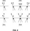
図2を参照すると、概略図20aは、光吸収性化学物質でできたラスターパターンを付着させた吸収フィルタの原理を示し、矢印の長さ及び傾きはフィルタに到達した及びフィルタを離れる光の強さ及び角度の夫々を示す。吸収フィルタの吸光度は、フィルタ表面に到達する光の入射角に依存しない、即ち入射角β=90°の光に対して及び入射角が低い光に対して光の強さが同様に減少することが観察されるということを特徴とする。20bに概略に示すように本発明の装置に適用した場合、吸収はそれでも入射角に依存しない。しかしながら、本発明の装置及び吸収フィルタの吸光度はフィルタの中心で最大であり、周辺に向かって減少し、及びかくして強さの減少は周辺とひかくして中央で高い。
【0095】
均等に着色した又はシェードを付けた吸収フィルタの場合、フィルタは自己吸光度を有し、これはフィルタのシェード内の有効光路長に左右され、及びかくして入射角で決まる。従って、低い入射角の光の強さは、20a及び20bの概略と比較して更に減少する。
【0096】
概略図20cは、干渉フィルタの原理を示す。20cでは、フィルタの中央波長と対応する光がバンドパスフィルタに照射される。このような場合、入射角β=90°の光は全て透過する。しかしながら、上文中に説明したようにフィルタの中央波長がずれるため、入射角が低い光は部分的にしか伝達されない。干渉フィルタの透過は全フィルタ領域に亘って均等であるということは理解されるべきである。
【0097】
本発明の装置でのフィルタの適用20dについて、中央波長が実験波長よりも長いバンドパスフィルタが適用される。しかしながら、中央波長のずれにより、入射角β=90°の光が部分的にしか透過しないのに対し、入射角が低い光が完全に透過する。本発明によれば、フィルタの中心の表面に到達した光は、実際に、入射角βが90°と等しいか或いはこれに近いのに対し、フィルタの周辺に到達した光は入射角が低い。かくして、光は概略図20dに従って、即ちフィルタの中心を部分的に及びフィルタ周辺を完全に透過する。
【0098】
図3は、図1の吸収フィルタ19を示す。このフィルタの吸光度は、中心から周辺に向かって徐々に減少する。上文中に説明したように、フィルタは吸収が等しい5個の環状ゾーン21乃至25を有し、吸光度は、中央環状ゾーン21から周囲環状ゾーン25に向かって徐々に減少する。
【0099】
図4は、図1及び図3の吸収フィルタについて、吸光度を半径に対して示す。従って、0mm乃至0.4mmの半径範囲での吸光度は0.60であり、0.4mm乃至0.9mmの半径範囲での吸光度は0.40であり、0.9mm乃至1.4mmの半径範囲での吸光度は0.22であり、1.4mm乃至1.9mmの半径範囲での吸光度は0.10である。1.9mm以上の半径については、フィルタは吸光度を示さない。
【0100】
図5は、図1、図3、及び図4の吸収フィルタの算術モデルを示す。このようなモデルは、検出器の感度及び有効光路長の変化に帰せられる吸光度に対する補正を正確に表す。簡単のため、吸収フィルタの算術モデルは、図1、図3、及び図4の環状ゾーン吸収フィルタとほぼ同じである。
【0101】
図6は、吸光度が中心から周辺に向かって徐々に減少する吸収フィルタを示す。このフィルタでは、個々の環状ゾーンは、均等な最大吸光度ABSmaxのサブゾーン、及び吸光度がないサブゾーン示す。図示の吸収フィルタは、5個の環状ゾーン31乃至35を有する。かくして中央環状ゾーン31の全サブゾーン31aは均等な最大吸光度を示し、環状ゾーン32乃至34のサブゾーン32a乃至34aは均等な最大吸光度を示し、周辺環状ゾーン35の全サブゾーン35aは吸光度を示さない。従って、吸光度は中央から周辺に向かって徐々に減少する 最大吸光度のサブゾーンが、吸光度を示さないサブゾーンに対して減少するためである。
【0102】
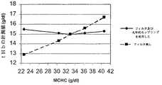
図7は、図1、図3、及び図4の、例えば例1及び比較例1の装置及び吸収フィルタを使用して本発明のフィルタ付きで又は無しで得られた、実験により見出した全ヘモグロビン濃度を示す。
【0103】
図8は、本発明の装置での干渉フィルタの使用原理を示す。この図は、中央波長が520nmのバンドパスフィルタの吸光度特性を示す。中央波長は、非散乱光(41:0°)と比較して散乱角が高い光(42:20°、43:40°、及び44:60°)に露呈したとき短い波長にずれる。本発明によれば、測定を行うためにフィルタの中央波長よりも13.5nm短い波長の光、即ち506.5nmの光を加えたとき、吸光度は散乱角の増大に従って減少し、41aでは0°での吸光度が0.6であり、42aでは20°での吸光度が0.4であり、43aでは40°での吸光度が0.1であり、44aでは60°での吸光度が0.0である。
【0104】
図9は、散乱、フィルタ、及び検出器の幾何学的配置を示す。散乱角αでの光の散乱が、厚さd=0.1mmの試料チャンバ16の中央で起こるものと仮定すると、0°乃至70°の散乱角αによって画成された検出範囲を持つフィルタ18及び検出器19は、試料チャンバの中央から距離l=1.05mmのところに位置決めされる。
【0105】
例1:全血試料について図1による装置を使用して光学測定を行った。
実験は、五つの試料について37℃で行なった。各試料のtHb値は15.0g/dlであるが、MCHC値は、夫々、22.6g/dl、30.4g/dl、33.0g/dl、36.3g/dl、及び40.6g/dlである。
【0106】
tHbが15.0g/dlでMCHCが33g/dlの試料を使用して装置を較正する。かくして標準MCHC値であるMCHC=33g/dlでは、実験により、tHb値が15.0g/dlであることがわかる。
【0107】
MCHC=30.4g/dl並びにMCHC=36.3g/dlでは、15.1g/dlのtHb値が得られる。MCHC=22.6g/dlでは、15.5g/dlのtHb値が得られるが、tHbの実験値は、MCHC=40.6g/dlで15.3g/dlであった。
【0108】
比較例1:例1と同様であるが、フィルタ及び光学的カップリングが光路内にない実験で、tHbを同様に決定する。
フィルタを除外した装置を、tHbが15.0g/dlでMCHCが33g/dlの試料を使用して較正する。かくして、MCHC=33g/dlでは、実験により15.0g/dlのtHbが得られる。
【0109】
MCHC=30.4g/dlでは、14.3g/dlのtHb値が得られるのに対し、MCHC=36.3g/dlでは、15.6g/dlのtHb値が得られる。MCHC=22.6g/dlでは、12.9g/dlのtHb値が得られるが、tHbの実験値は、MCHC=40.6g/dlで16.7g/dlであった。
【図面の簡単な説明】
【図1】 本発明の装置の分解図である。
【図2】 吸収フィルタ及び干渉フィルタの原理並びに本発明の装置でのこれらのフィルタの使用を示す概略図である。
【図3】 吸光度が均等な環状ゾーンを持つ図1の吸収フィルタの図である。
【図4】 図1の吸収フィルタについての吸光度を半径に対して示すグラフである。
【図5】 図1の吸収フィルタの吸光度の算術モデルを示すグラフである。
【図6】 最大吸光度が均等なサブゾーン及び吸光度がない残りのサブゾーンを示す、環状ゾーンを持つ吸収フィルタの図である。
【図7】 本発明のフィルタを使用して又はフィルタ無しで実験的に見出した全ヘモグロビン濃度を示すグラフである。
【図8】 本発明の装置での干渉フィルタの使用原理を示すグラフである。
【図9】 散乱、フィルタ、及び検出器の幾何学的配置を示す概略図である。
【符号の説明】
13バンドパスフィルタ 14 キュベットハウス 14b サーモスタットジャケット14c 熱電対 15 試料キュベット 16 光透過性出口窓 17a 試料入口 17b試料出口 17c 液体センサ18 吸収フィルタ[0001]
BACKGROUND OF THE INVENTION
The present invention relates to an apparatus, sample cuvette, and method for optical measurement of samples exhibiting various levels of scattering, and more particularly to an apparatus, sample cuvette, and method for optical measurement of a sample of whole blood. About.
[0002]
[Prior art]
Optical measurements that determine the transmission of light across a sample from a light source by a detector are powerful tools for conducting a wide range of chemical and clinical studies. For an ideal sample, the absorbance is proportional to the concentration of the absorbing species in the sample as well as the thickness of the sample. Lambert-Beer's law shows this relationship as:
A = logI0/ I = εcd
Where I0And I are the intensity of incident light and transmitted light, respectively, c is the concentration of absorbing species, d is the thickness of the sample, and ε is the absorbance. The term logI0/ I is called absorbance A.
[0003]
However, scattering occurs for many real samples. Therefore, light transmission can be disturbed in various ways, which makes measurement difficult and must be corrected to obtain the correct values for their concentration and the parameters sought.
[0004]
One main reason for scattering is sample heterogeneity, because light scatters when interacting with particles of foreign samples. Therefore, light is not transmitted directly but is refracted over a predetermined scattering angle range. Scattered and scattered light have a circular symmetry and can be characterized by a scattering angle α.
[0005]
The scattering angle α is defined as the deviation of the angle of the scattered light from the central optical path of the light, and the vertex of the scattering angle is defined as the center of the sample chamber. The incident angle β of the light reaching the detector is defined as the angle between the incident light and the detector surface. The scattering angle α and the incident angle β are related to α + β = 90 ° for light scattered in an angle range of 0 ° to 90 °.
[0006]
Many phenomena associated with scattering make optical measurements difficult. Thus, the scattering of light at an angle α outside the detection range of the detector makes this part of the light unavailable for detection. Furthermore, many detectors are less sensitive to light with a small incident angle compared to light with an incident angle β = 90 °.
[0007]
Another phenomenon that must be considered is reflection. Light reflection occurs at any optical interface in the optical path. Light scattered at a large scattering angle tends to exhibit high reflection compared to unscattered light or light scattered at a small scattering angle. Finally, scattering increases the effective optical path length and thus the absorbance compared to unscattered light.
[0008]
The scattering coefficient is defined as the distribution of light intensity with respect to the scattering angle. Thus, these measurements governed by more than a certain amount of scattering have a high scattering coefficient, whereas measurements with low scattering have a low scattering coefficient.
[0009]
When the scattering coefficient is constant, the above-described phenomenon can be easily corrected in the data processing process of the measured value. Unfortunately, however, the scattering coefficient is not constant and varies according to a range of sample parameters.
[0010]
This phenomenon of changing the scattering coefficient makes measurement more difficult. Thus, measurements that are affected by scattering beyond the range of the detector erroneously display absorbing species concentrations that are too high. However, there is no direct way to determine the level of light that was not detected.
[0011]
The measurement of the high scattering coefficient has a high light level with a low incident angle. Since the sensitivity is low in such a state, the detector erroneously displays too high absorption and too high concentration of the absorbing species. However, since the scattering coefficient varies depending on the sample, this phenomenon cannot be corrected immediately in the data processing step.
[0012]
When the scattering coefficient changes, the reflection level changes as well. When the reflection coefficient is high, which often occurs when the scattering coefficient is high, a certain amount of light is lost, and the high concentration of the absorbing species is erroneously displayed. As explained above, there is no immediate way to determine the loss due to reflection.
[0013]
Furthermore, the change in the scattering coefficient affects the absorbance as described above and changes the effective optical path length. Although a sample with a high scattering coefficient is falsely indicated as having a high concentration of absorbing species, the increase in absorption is actually due to an increase in effective optical path length. The effective optical path length varies from sample to sample and cannot be determined immediately.
[0014]
An important example of such a sample that is adversely affected by changes in the scattering coefficient is whole blood, ie non-hemolyzed blood and therefore highly heterogeneous blood.
For whole blood, parameters and components conventionally measured by optical methods are total hemoglobin concentration (tHb), hematocrit value (HCT), ie the proportion of red blood cells to the total volume of blood, and glucose concentration. Specific hemoglobin derivatives such as oxyhemoglobin, deoxyhemoglobin, methemoglobin, carbon monoxide hemoglobin, and sulfhemoglobin, as well as bilirubin and diagnostic dyes are examples of other species that are measured using optical principles.
[0015]
In whole blood, concentration, osmotic volume change, blood cell aggregation and formation are all parameters that affect the scattering coefficient.
With respect to blood cell concentration, maximum scatter is observed for samples with a typical range of HCT of 40% to 50%. Samples with higher or lower HCT have a lower scattering coefficient.
[0016]
The scattering coefficient is further dependent on the mean hemoglobin concentration (MCHC). Mean hemoglobin concentration (MCHC) is defined as the ratio between (tHb) and (HCT) (MCHC = tHb / HCT). MCHC is thus the concentration of hemoglobin in blood cells and is an important parameter in understanding changes in blood cell penetration volume.
[0017]
The permeation volume change is caused by a change in electrolyte concentration and thus affects the scattering coefficient. When the concentration is high, for example, when the salinity is high, osmosis causes a flow of water from the blood cells to the plasma phase, during which time the blood cells contract and scattering increases. Thus, the two blood samples have similar hemoglobin concentrations, but the blood cell contraction is high—and thus the MCHC is high—the sample appears to have a high hemoglobin concentration.
[0018]
It was observed that at a given tHb, the error for the experimental determination of tHb varies according to MCHC. Thus, at a typical level of tHb of 15 g / dl, the experimentally determined tHb changes by about ± 4% when the MCHC changes by ± 10%. If the MCHC is greater than this, eg, changes by ± 25%, the experimentally determined tHb changes by about ± 13%. This is unacceptable for clinical purposes. See Example 1 and Comparative Example 1.
[0019]
Other phenomena that affect the scattering coefficient are blood cell aggregation, precipitation, and abnormal formation observed in sickle cell disease. Thus, when agglomeration and precipitation occurs, the coefficient decreases and falsely displays a hemoglobin concentration that is too low compared to a non-precipitated sample. Abnormal formation also changes the scattering coefficient.
[0020]
The perfect scattering phenomenon and its level of change are very complex because the level of scattering is more greatly influenced by the concentration of specific lipids and proteins. Therefore, many patents have dealt with the problem of measuring blood parameters by optical methods such as photometry and spectroscopy. These patents can be divided into two groups. The first group pursues a geometric solution to the problem, and the second group pursues a solution based on multi-wavelength technology. Other patents of the first group include European Patent No. EP575712A2 awarded to the University of Manitoba, Canada, which discloses a method and apparatus for measuring blood parameters. According to the method of this patent, the changes in the directly emitted light and photometrically measured scattered light are compared with one or more criteria, taking into account the effect of changes in light scattering, for example due to blood sodium concentration. . According to this method and apparatus, light is detected with a minimum of two detection means. The first detection means detects the light that directly comes out, and the other detection means when two or more second detection means and detection means are provided detects the scattered light. Comparing the measured values obtained at the same time with a reference or a calculated reference stored in the system, a scatter distribution curve of the sample is calculated and scatter is taken into account. As will be apparent, the reliability of the method and apparatus is determined by whether or not the proper criteria are obtained.
[0021]
U.S. Pat. No. 5,385,539, granted to Advanced Harmo Technology, USA, discloses a method and apparatus for online measurement of blood HCT values based on a minimum of two light detection means. ing. The first of the least two light detection means receives light that has not been scattered or light that has been slightly scattered, i.e. light that has been slightly scattered due to a small scattering angle. So that it is positioned. The second of the at least two light detection means is positioned to receive light scattered at a high angle, i.e., light that has traveled across a large distance across the blood sample. The system further includes a light intensity adjustment means for adjusting the light so that the light received by one detection means is emitted at an intensity such that it is a constant value. In this method, the light received by the other detection means is shown so that the HCT value is linear. In a preferred embodiment of the present invention, an optical fiber is used as a conveying means for transmitting light. This patent further discloses a laboratory instrument that applies a “backscatter” geometry, in accordance with which the detection means is positioned relative to the blood sample on the same side as the luminescent source. .
[0022]
U.S. Pat. No. 5,601,080 issued to Coletech Medical Technology, Canada, discloses a method and apparatus for applying a light source and detection means for on-line spectroscopic measurement of blood parameters. The method and apparatus are characterized by including one or more light sources or two or more detectors.
[0023]
International patent application WO 96/37767 granted to LXR Biotechnology Inc. in the United States discloses the use of a wide angle scatter detector applied to a collector for highly scattered light. This then leads to a separate detector and is specifically determined.
[0024]
Japanese Patent No. JP10132728A granted to Nippon Koden of Japan discloses a pattern of concentrically distributed detectors that collect light scattered at a scattering angle α when measuring white blood cells. The experimental instrument further has a readout section corresponding to each of the specific circular areas of the detection pattern.
[0025]
U.S. Pat. No. 5,963,335, granted to Waters Instruments, Inc. of the United States, describes the absorption of radiation, in particular the whole blood that constitutes an occluder in the optical path between the light source and the detector. A method and apparatus for measuring absorption in a sample is disclosed. The three measured occlusion radiation patterns are characterized by comparing obturators in three different locations and eliminating the radiation attenuation factor.
[0026]
Although the geometric configurations and methods disclosed in the above-mentioned patents and patent applications can reduce the effects of changes in the scattering coefficient, they are complicated by the need for sophisticated and expensive laboratory equipment and complex work. Or the complete spectrum of the problems described above cannot be solved.
[0027]
A second group focused on multi-wavelength techniques, such as spectroscopy, includes the patents and patent applications listed below.
International patent application WO 94/08237 granted to the University of Texas System in the US discloses a method and apparatus for accurately determining the concentration of a number of specific hemoglobin species in a whole blood sample spectrophotometrically. . According to this, a whole blood sample is irradiated with a plurality of radiation wavelengths selected by the ability to distinguish hemoglobin species with minimal scattering and maximum absorption. According to this method, a wavelength that is considered redundant compared to the number of specific hemoglobin species is added with the method. According to this method, various light scattering losses are treated as a function of wavelength and the concentration of a particular hemoglobin species. The seed concentration is calculated based on a predetermined molar absorbance. This patent application further discloses reducing the problem of scattering beyond the detection range by using a large detector.
[0028]
European Patent No. EP210417B1, granted to the Danish radiometer A / S, discloses a method and apparatus for spectroscopically determining (n-1) specific hemoglobin species. This exposes a turbid sample of whole blood or hemolyzed blood to at least n different wavelengths of light, measures at least one turbidity component with (n-1) hemoglobin species, and then This is based on calculating the concentration of the species from the molar absorbance.
[0029]
European patent application EP800074A1 granted to AVL Medical Instruments AG in Switzerland uses two detection arrangements to determine n hemoglobin species and calculate the species concentration from a given molar extinction rate. , And using n different wavelengths and 2n measurements. The detector arrangement includes optical means such as a lens to improve the separation between directly transmitted and scattered light.
[0030]
The method and apparatus of the spectroscopic technique represents a complete way to eliminate the problems associated with changes in the scattering coefficient in that it is directly involved in the scattering phenomenon. However, the spectroscopic multi-wavelength method is complicated because it requires sophisticated and expensive laboratory equipment and complex operations.
[0031]
[Problems to be solved by the invention]
Accordingly, there is a need for a simple method and apparatus for accurately and optically measuring samples with varying scattering coefficients, particularly blood samples with varying scattering coefficients. In particular, there is a need for a simple method and apparatus that corrects for the effects of changes in effective light path length, detector sensitivity, and the fact that light is not detected due to reflections and scattering out of the detector range.
[0032]
[Means for Solving the Problems]
This has been done by an apparatus according to the invention for optically measuring a light scattering sample, comprising at least one light emitting means, a sample cuvette with a sample chamber, a filter and a detection means. This apparatus is characterized in that a filter is positioned in the optical path between the sample cuvette and the detection means, and this filter is an absorption filter whose absorbance gradually decreases from the center toward the periphery.
[0033]
According to a preferred embodiment of the present invention, the optical measurement device comprises hemoglobin, oxyhemoglobin, deoxyhemoglobin, methemoglobin, carbon monoxide hemoglobin, sulfhemoglobin, bilirubin, diagnostic dye, and / or any other light absorption An apparatus for optically measuring the concentration of a compound, preferably the concentration of hemoglobin in a whole blood sample, and / or the oxygen saturation level.
[0034]
An absorption filter is defined as a filter that absorbs light by a light-absorbing compound such as a metal or metal oxide attached to or incorporated in a carrier such as glass or polymer foil. Thus, the absorption filter may have a multilayer structure or a single layer structure.
[0035]
The absorption filter absorbs light in a predetermined wavelength range. This range is narrow, for example, in that it absorbs only green light, or is broad, for example, in that it absorbs any visible light, and the absorbance is independent of the incident angle of light that reaches the filter surface. The light absorbing compound of the absorption filter can be selected to properly absorb ultraviolet, visible, or infrared light.
[0036]
The light absorbing compound of the absorption filter may be attached or incorporated as a macroscopic pattern of a fully absorbing raster. If the density of the raster is high and thus the area of the carrier bare is small, the absorption filter shows a high absorbance. Similarly, if the density of the raster is low, and thus the area of the exposed carrier is high, the absorption filter exhibits a low absorbance. The raster-based absorbance is unequal at the microscopic level, but is equivalent when viewed macroscopically.
[0037]
The light absorbing compound is microscopically attached or incorporated to evenly color or shade, i.e., partially absorb. This can be done, for example, by sputtering techniques. Thus, when the shadow is dark, the absorbance increases, and when it is lightly shaded, the absorbance decreases. The absorbance obtained by applying the shadow is microscopically as well as macroscopically uniform.
[0038]
Scattering angle αn-1And αnScattering angle range betweennAbsorbance F (α ′ of the annular zone of the absorption filter characterized byn) Is defined as the logarithm of the ratio of the intensity of light of a given wavelength incident on the annular zone to the intensity of light of that given wavelength transmitted across the annular zone.
[0039]
Thus, the absorption filter of the present invention has a scattering angle range α ′.s And α 't For any two annular zones of the filter characterized by the corresponding absorbance F (α ′s) And F (α 't) Is α 's<Α 'tIn other words, the scattering angle range α ′t Is the scattering angle range α 'sF (α 's)> F (α 't).
[0040]
Absorbance F (α 'n) Is the scattering angle α 'nProvided by any distribution of absorption zones within the annular zone characterized by: Thus, a complete annular zone exhibits a uniform absorbance, or a uniform maximum absorbance subzone, and no absorbance in the remaining subzones.
[0041]
In a variant, the device according to the invention for optically measuring a light scattering sample comprises a light emitting means, a sample cuvette with a sample chamber, a filter, and a detection means, the optical path between the sample cuvette and the detection means The filter is positioned so that each of the center wavelength and the cutoff wavelength is preferably 1% to 25%, more preferably 5% to 20%, and even more preferably the wavelength of light from the light emitting means. Is 10-20% longerBandpass filterAnd an interference filter selected from the group consisting of long wavelength path filters.
[0042]
The center wavelength and the cutoff wavelength of the interference filter correspond to ultraviolet light, visible light, or infrared light as appropriate.
The filter is provided as a separate component or as an integral part of the sample cuvette, for example printed directly on the light exit window of the sample cuvette or as an integral part of the detector. Therefore, a sample cuvette with an integrated filter may be a disposable unit that is used for only one or several measurements.
[0043]
Thus, the present invention further covers a sample cuvette for optically measuring a light scattering sample, including a sample chamber and an absorption filter. The sample cuvette is provided with a light entrance window and a light exit window, respectively, on the wall defining the sample chamber, and the absorption filter is an integral part of the sample cuvette and on or in the exit window of the sample cuvette. The absorbance of the absorption filter decreases from the center to the periphery of the filter.
[0044]
Furthermore, the present invention covers a sample cuvette for optically measuring a light scattering sample, including a sample chamber and an interference filter. The sample cuvette has a light entrance window and a light exit window on the wall defining the sample chamber, and the interference filter is an integral part of the sample cuvette and on or in the exit window of the sample cuvette. The interference filter isBandpass filterAnd a long wavelength pass filter.
[0045]
The sample cuvette may be made entirely of a light transmissive material, or the cuvette wall may have a defined light transmissive region that forms an entrance window and an exit window for light. In the former case, the window does not appear to be a bounded area. The term window is used herein in both examples to indicate the area of the sample chamber and cuvette wall through which light enters and exits.
[0046]
The detection means of the apparatus of the present invention is preferably a detector having a large area covering a wide scattering angle range. Thus, the detector preferably covers a scattering angle of up to 70 °. The distance between the center of the sample chamber and the detector is a maximum of 1.5 mm, so the active area of the detector is preferably about 0.25 mm.2 Or more.
[0047]
An optical coupling may be introduced between the sample chamber of the device and the filter and / or between the filter and the detector to suppress light reflection. Such an optical coupling may be a layer of glycerol, silicone or acrylate having a thickness of 1 μm to 100 μm.
[0048]
The apparatus further includes a hole disposed between the light source and the sample cuvette. The hole may be circularly symmetric or symmetric other than circularly symmetric. In both of these cases, the filter is symmetric corresponding to the hole feature. Therefore, since the scattering phenomenon itself is circularly symmetric, for example, the symmetry of the filter corresponding to the rectangular hole is elliptical.
[0049]
The invention further relates to a method for using a device or sample cuvette of the invention for optically measuring a light scattering sample, in particular for optically measuring blood parameters, in particular total hemoglobin concentration. . However, the apparatus and method of the present invention are not limited to optical measurement of total hemoglobin concentration, and certain hemoglobin derivatives such as oxyhemoglobin, deoxyhemoglobin, methemoglobin, carbon monoxide hemoglobin, and sulfhemoglobin, and bilirubin, It is also associated with optical measurements of diagnostic dyes and / or any other light-absorbing compounds present in the blood. Similarly, whole blood oxygen saturation can be determined by optical methods.
[0050]
Measurements can be made in the fluidized state as well as in the non-fluidized state. Furthermore, optical measurements can be made using one wavelength, preferably an isobestic wavelength, but these measurements use only one wavelength if the filter is an interference filter. It can also be done using multiple wavelengths to conditionally determine multiple concentrations and / or parameters simultaneously.
[0051]
According to a preferred embodiment of the method of the invention, the optical measurement is performed using at least two wavelengths, preferably two wavelengths, to simultaneously determine the hemoglobin concentration and oxygen saturation level of the blood sample.
[0052]
A method and apparatus for performing optical measurements under conditions of varying scattering coefficients will be described based on the applicant's experience with measurements on whole blood. However, the present invention is not limited to this. As will be apparent from the description of the present invention, the principles of the method and apparatus can be applied to the optical measurement of any sample of biological, physiological or chemical samples with varying scattering coefficients. Among other things, such samples include milk, wastewater, and paint.
[0053]
The absorbance of the absorption filter of the present invention gradually decreases from the center of the filter toward the periphery. Such a filter can correct for variations in scattering coefficient and effective optical path length associated with changes in detector sensitivity.
[0054]
The sensitivity of the detector changes continuously according to the incident angle of light. Thus, it has been found that the sensitivity of many optical detectors varies with angle. This can be modeled as an angular range dependent vector of detector angular absorbance (DAA) counted in dimensionless units of absorbance.
[0055]
Thus, the DAA vector has a different scattering angle range α ′.1, Α '2, Α 'Three, ..., α 'n, ..., α 'maxIt relates to the absorbance observed over time. Where α '1Is α0= 0 ° and α1Α ′ for the central range of small scattering angles betweennIs αn-1And αnΑ ′ for any range of scattering angles betweenmaxIs the maximum scattering angle range that can be detected by the detector means, in this case the angle αmax-1Is the maximum detectable angle αmaxConcerning the angle between. In such a case, the DAA vector is (DAA (α ′1), DAA (α '2), DAA (α 'Three), ..., DAA (α 'n ), ..., DAA (α 'max)).
[0056]
The detector angular absorbance and the corresponding arithmetic function DAA (α) can be used for modeling as well. One group of such functions are trigonometric functions, specifically cosine functions, but other functions can be used for modeling as well.
[0057]
For a given sample absorption, the effective optical path length varies according to the scattering angle. Thus, it has been found that scattering contributes to absorbance in a way that can be modeled as an angle-dependent vector of path length angle absorbance (PAA) counted in dimensionless units of absorbance.
[0058]
On the other hand, the DAA vector does not depend on the absorption of the sample, and the PAA vector depends on the absorption of the sample.
Thus, the vector of PAA has another scattering angle range α ′ defined above.1, Α '2, Α 'Three, ..., α 'n, ..., α 'max It relates to the absorbance observed over time. Where the PAA vector is (PAA (α ′1), PAA (α '2), PAA (α 'Three), ..., PAA (α 'n), ..., PAA (α 'max)).
[0059]
Any arithmetic function PAA (α) corresponding to the path length angle absorbance can be used for modeling as well. In the simple method, scattering occurs at the scattering angle α in the center of the sample, and scattering does not occur many times, ie no further scattering occurs. Compared with the optical path length d of non-scattered light, the scattered light moves by a distance d (α) = 0.5d + 0.5d / cosα. Based on such an arithmetic model and boundary conditions, the function PAA (α) can be determined.
[0060]
Thus, in order to correct for changes in detector sensitivity and effective optical path length, the absorption filter has a different scattering angle range α ′.1, Α '2, Α 'Three, ..., α 'n, ..., α 'max With an angular range-dependent absorbance F observed over the range F (α ′n) = ABSmax-(DAA (α 'n) + PAA (α 'n)). This decreases from the center of the filter toward the periphery. Where ABSmaxIs the central angle range α '1Is the maximum absorbance of the filter applied to.
[0061]
Maximum filter absorbance ABSmaxIs DAA (α 'max) + PAA (α 'max For example, the absorbance is the angular sensitivity of the detector and the outer angular range α ′.maxIt can be attributed to the effective optical path length. Preferably ABSmaxIs DAA (α 'max) + PAA (α 'max).
[0062]
The absorption filter can also be called an internal transmittance filter or a transmittance filter. In the prior art, such filters with gradually decreasing absorbance are well known in the field of optics.
[0063]
U.S. Pat. No. 4,298,275 issued to Xerox Corporation of the United States for a copier, including a filter having an absorption curve characterized by a gradual decrease in absorbance from the center to the periphery of the filter A wide angle exposure system is disclosed. Similarly, U.S. Pat. No. 4,906,081, issued to Ricoh Company, Japan, describes the perimeter of the filter via the minimum absorbance at the axial center to the maximum absorbance at the annular zone around the axial center. A filter is disclosed in which the absorbance curve in the range up to the minimum absorbance is symmetrical, and this filter is used in imaging optical systems.
[0064]
However, both U.S. Pat. No. 4,298,275 and U.S. Pat. No. 4,906,081 teach that an absorption filter with reduced absorbance is used with a light scattering sample in the optical path of an optical measurement device. Not disclosed. In particular, these patents do not teach at all the use of such filters to mitigate the problems associated with optical measurements that are influenced by changes in the scattering coefficient. Thus, to the best of Applicants' knowledge, the apparatus, sample cuvette, and method of the present invention are novel.
[0065]
In one embodiment of the invention, the number n of annular zones of the absorption filter is 2 to 10, preferably 2 to 7. More preferably, n is 5.
Therefore, it was found that at a hemoglobin concentration of about 15 g / dl, which is a normal concentration of human blood, the lower absorption filter having five scattering angle ranges corrects changes due to scattering well.
[0066]
Thus, this absorption filter has an absorbance F (α ′ for α ′ ranges of 0 ° to 20 °, 20 ° to 40 °, 40 ° to 50 °, 50 ° to 60 °, and 60 ° or more.n) Is F (0 ° -20 °) = ABSmax= 0.40 to 0.90, F (20 ° -40 °) = 0.25 to 0.60, F (40 ° -50 °) = 0.10 to 0.40, F (50 ° -60 °) = 0.05 to 0.25, and F (60 °-) = 0.00. Where any two scattering angle ranges α ′sAnd α 't And α 's<Α 'tIf so, for example, the scattering angle range α ′t Is the scattering angle range α 'sF (α 's )> F (α 't).
[0067]
In another preferred embodiment of the present invention, the absorbance F (α ′n ) Is F (0 ° -20 °) = ABSmax= 0.50 to 0.80, F (20 ° -40 °) = 0.30 to 0.50, F (40 ° -50 °) = 0.15 to 0.30, F (50 ° -60 °) = 0.05 to 0.15, and F (60 °-) = 0.00. Where any two scattering angle ranges α ′sAnd α 'tAnd α 'tIs α 's F (α 's)> F (α 't).
[0068]
For blood samples with a hemoglobin concentration of 15 g / dl above or below, the correction is provided in the same way as the upper filter, but is partial compared to the optical correction in the case of 15 g / dl.
[0069]
In a variant of the invention, the filter is an arbitrary arithmetic function G (α) = ABSmaxAbsorbance modeled by-(DAA (α) + PAA (α)). Where ABSmax, DAA (α), and PAA (α) are defined above.
[0070]
In a preferred embodiment of the present invention, the absorption filter is made of a polyester foil having a thickness of 20 μm to 150 μm obtained by developing a silver raster pattern having a thickness of 0.1 μm to 5 μm and a raster size of 10 μm to 200 μm by photographic technology. Yes.
[0071]
In a variant of the invention, the device preferably has a central wavelength and a cutoff wavelength of 1% to 25%, more preferably 5% to 20%, even more preferably 10% to more than the wavelength of light from the light emitting means. 20% longerBandpass filterThere is an interference filter of the type or long wavelength pass filter type, which is positioned between the sample cuvette of the device and the detection means.
[0072]
The interference filter of the present invention is uniform in transmission over the entire filter range and does not require accurate centering compared to the absorption filter. These filters include a carrier such as glass or polymer foil with a metallic optical interference layer attached.
[0073]
When exposed to light having a small angle compared to light having an incident angle β = 90 °, the interference filters of the group shift each of the center wavelength and the cutoff wavelength to a shorter wavelength. Therefore, light of the measurement wavelength is completely transmitted only when the incident angle is low, that is, when the scattering angle is high, whereas light having a high incident angle, that is, light with a low scattering angle, is partially transmitted. Only transmits or does not transmit at all.
[0074]
The apparatus of the present invention described above including the interference filter provides a technical solution to the problem described above that the scattering coefficient changes. This is because the effects of changes in the effective optical path length and detector sensitivity can be corrected. Specifically, the transmission pattern provided by the interference filter when applied to the device is similar to the transmission pattern of the absorption filter described above.
[0075]
The use of these interference filters in prior art interference filters and detection systems for optical measuring devices is well known. Thus, U.S. Pat. No. 4,303,336 granted to Baxter Trabenol Laboratories in the United States, Scrabo S. p. U.S. Pat. No. 5,088,493 granted to A and U.S. Pat. No. 5,478,750 granted to Avaquis, Canada, all describe the use of interference filters in detection systems. Yes.
[0076]
However, all the above-mentioned patents describe the use of interference filters for performing wavelength filtering, branching, etc., and of these patents, each of the filter's center wavelength and cutoff wavelength emits light. None of the teachings of an apparatus for making an optical measurement of a light scattering sample characterized in that it is longer than the wavelength of the light from the means and such a filter reduces the transmission of light of high incidence angle .
[0077]
In one embodiment, the interference filter is made of glass having a thickness of 100 μm to 500 μm with an optical interference layer made of metal attached to the surface.
In a preferred embodiment, the interference filter has a central wavelength longer than the wavelength of the light from the light emitting means, preferably 1% to 25% longer, more preferably 5% to 20% longer, even more preferably 10% to 20%. %longBandpass filterIt is. For a preferred experimental wavelength of 500 nm to 510 nm,Bandpass filterThe central wavelength is preferably 505 nm to 630 nm, more preferably 530 nm to 600 nm, and still more preferably 550 nm to 600 nm.
[0078]
In another preferred embodiment, the interference filter has a cutoff wavelength that is longer than the wavelength of the light from the light emitting means, preferably 1% to 25% longer, more preferably 5% to 20% longer, and even more preferably 10%. It is a long wavelength pass filter that is 20% to 20% longer, and has a steepness per nm of 0.5% to 2% (absorption). For the preferred experimental wavelengths of 500 nm to 510 nm, the cutoff wavelength of the long wavelength pass filter is 505 nm to 630 nm, more preferably 530 nm to 600 nm, and even more preferably 550 nm to 600 nm.
[0079]
In contrast, the use of filters in the device is focused on changes in the angular sensitivity and effective optical path length of the detector, and undetected light is mainly a detector that covers a wide range of scattering angles. This is solved by using a large area.
[0080]
Thus, in a preferred embodiment of the invention, the detection range of the detector is defined by an angle α of at least 0 ° to 50 °, preferably 0 ° to 65 °, more preferably 0 ° to 70 °. The detection may be any detector applicable to the detection of light of the applied wavelength, but preferably the detector is a silicon photodiode.
[0081]
In another preferred embodiment of the invention, the distance between the center of the sample chamber and the detector is in the range of 0.2 mm to 1.5 mm, preferably in the range of 0.2 mm to 1.0 mm. More preferably, it is in the range of 0.5 mm to 1.0 mm. Therefore, the active area of the detector is 25 mm2 That's it. Preferably, the detection area is 70 mm2 Or more, more preferably 100 mm2 That's it.
[0082]
In order to reduce the reflection of light in the optical path, optical coupling should be introduced into the device. Thus, in one preferred embodiment of the invention, the device further comprises at least one optical coupling positioned between the sample and the filter and / or between the filter and the detection means. Such optical coupling is a thin layer made of a low-absorbance material, preferably a material having the same refractive index as the adjacent component. Such optical coupling materials must be chemically stable and in particular chemically stable against oxidation.
[0083]
Thus, the optical coupling is formed from glycerol, silicone, or acrylate, preferably from silicone oil, silicone resin, or acrylate resin, and layered in a thickness of 1 μm to 100 μm, preferably 5 μm to 50 μm. Applied.
[0084]
In a preferred embodiment, the device is provided with a hole located between the light source and the sample chamber. Preferably, the area of this hole is 1 mm2 It is as follows.
In order to optimize the absorption filter according to the invention, a procedure based on empirical information about the angular sensitivity of the detector and the absorbance and scatter for the selected blood sample is applied.
[0085]
Therefore, the DAA vector is estimated from a blank experiment that exposes the detector to light with varying incident angles based on the detector specifications. The DAA vector is estimated from empirical data on scatter and absorbance of a whole blood sample, preferably a representative whole blood sample with varying scatter coefficients at a hemoglobin concentration of about 15 g / dl. Based on estimates of these vectors, ABSmaxAnd αmaxForms a series of filters with different values. An optimal filter is designed based on the mapping of the error obtained when these two parameters change, for example, for the experimentally found hemoglobin concentration versus the MCHC value.
[0086]
In order to optimize the interference filter according to the invention,Bandpass filterA series of filters with different bandwidths and central wavelengths are formed, and a series of filters with different steepness and cut-off wavelengths are formed for the long wavelength path filters. An optimal filter is designed based on the mapping of the error obtained when these two parameters change, for example, for the experimentally found hemoglobin concentration versus the MCHC value.
[0087]
The measurement can be performed in a flowing state, i.e., the sample flowing through the sample chamber during the measurement, as well as in a non-flowing state. In particular, the simple method and measurement of the present invention allows the measurement to be performed quickly, thereby reducing aggregation and precipitation in the whole blood sample. Furthermore, this method in particular solves the problem of scattering due to blood cell aggregation, so that the method is particularly suitable for non-flow measurements.
[0088]
Optical measurements can be made using a single wavelength, but such measurements can also be made using multiple wavelengths to simultaneously determine multiple concentrations and / or parameters. If the filter is an interference filter, only one wavelength is used.
[0089]
Preferably, the measurement is performed at an isobestic wavelength, i.e. tHb at the same wavelength where the absorbance of oxyhemoglobin and deoxyhemoglobin is the same. One such preferred wavelength is 506.5 nm.
[0090]
DETAILED DESCRIPTION OF THE INVENTION
Referring to FIG. 1, which is an exploded view of the device of the present invention, the device includes light emitting means 12 which is an HLMP-CE23-R0000 diode available from Hewlett-Packard Company. This light emitting means is positioned by two polymer guides 11 and 11a. These polymer guides have an area of 1 mm2 Holes are provided.
[0091]
Center wavelength 506.5nm available from Ferroperm Optic in DenmarkBandpass filter13 determines the wavelength of light entering the cuvette houses 14 and 14a. The
[0092]
A thermostat jacket 14b heats the cuvette houses 14 and 14a to 37 ° C. and monitors this with a thermocouple 14c.
The
[0093]
The
The optical coupling made of a thin layer of glycerol positioned between the sample cuvette and the filter and between the filter and the detector is not shown in FIG.
[0094]
Referring to FIG. 2, a schematic diagram 20a shows the principle of an absorption filter with a raster pattern made of a light-absorbing chemical, with the length and slope of the arrows reaching the filter and the intensity of light leaving the filter. Each of the height and angle is shown. The absorbance of the absorption filter does not depend on the incident angle of the light reaching the filter surface, ie the light intensity decreases for light with an incident angle β = 90 ° and for light with a low incident angle. Is observed. When applied to the apparatus of the present invention as shown schematically in 20b, the absorption is still independent of the angle of incidence. However, the absorbance of the device and absorption filter of the present invention is greatest at the center of the filter and decreases towards the periphery, and thus the decrease in strength is high at the periphery and thus at the center.
[0095]
In the case of an evenly colored or shaded absorption filter, the filter has self-absorbance, which depends on the effective optical path length in the filter shade and thus depends on the angle of incidence. Thus, the light intensity at low incident angles is further reduced compared to the outline of 20a and 20b.
[0096]
The schematic diagram 20c shows the principle of the interference filter. In 20c, the light corresponding to the center wavelength of the filter isBandpass filterIs irradiated. In such a case, all light having an incident angle β = 90 ° is transmitted. However, as described above, since the center wavelength of the filter is shifted, light having a low incident angle is transmitted only partially. It should be understood that the transmission of the interference filter is uniform across the entire filter area.
[0097]
For
[0098]
FIG. 3 shows the
[0099]
FIG. 4 shows the absorbance versus radius for the absorption filter of FIGS. Therefore, the absorbance in the radius range from 0 mm to 0.4 mm is 0.60, the absorbance in the radius range from 0.4 mm to 0.9 mm is 0.40, and the radius range from 0.9 mm to 1.4 mm. The absorbance at 0.2 is 0.22, and the absorbance in the radius range of 1.4 mm to 1.9 mm is 0.10. For radii greater than 1.9 mm, the filter shows no absorbance.
[0100]
FIG. 5 shows an arithmetic model of the absorption filter of FIGS. 1, 3, and 4. Such a model accurately represents the correction for absorbance attributed to changes in detector sensitivity and effective path length. For simplicity, the arithmetic model of the absorption filter is almost the same as the annular zone absorption filter of FIGS.
[0101]
FIG. 6 shows an absorption filter in which the absorbance gradually decreases from the center toward the periphery. In this filter, the individual annular zones have a uniform maximum absorbance ABS.maxAnd subzones without absorbance. The illustrated absorption filter has five
[0102]
FIG. 7 shows the total hemoglobin found by experiment, obtained with or without the filter of the present invention using, for example, the apparatus of Example 1 and Comparative Example 1 and the absorption filter of FIG. 1, FIG. 3 and FIG. Indicates the concentration.
[0103]
FIG. 8 shows the principle of use of the interference filter in the device of the invention. This figure shows that the central wavelength is 520 nmBandpass filterThe absorbance characteristics of are shown. The central wavelength shifts to a shorter wavelength when exposed to light (42: 20 °, 43: 40 °, and 44: 60 °) with a higher scattering angle compared to non-scattered light (41: 0 °). According to the present invention, when light having a wavelength 13.5 nm shorter than the center wavelength of the filter, that is, light of 506.5 nm, is added for measurement, the absorbance decreases as the scattering angle increases, and 0 ° at 41a. The absorbance at 20 ° is 0.4 at 42a, the absorbance at 20 ° is 0.4 at 43a, the absorbance at 40 ° is 0.1 at 43a, and the absorbance at 60 ° is 0.0 at 44a. is there.
[0104]
FIG. 9 shows the scatter, filter, and detector geometry. Assuming that light scattering at the scattering angle α occurs in the center of the
[0105]
Example 1: Optical measurements were performed on whole blood samples using the apparatus according to FIG.
The experiment was performed at 37 ° C. for five samples. The tHb value for each sample is 15.0 g / dl, but the MCHC values are 22.6 g / dl, 30.4 g / dl, 33.0 g / dl, 36.3 g / dl, and 40.6 g / dl, respectively. dl.
[0106]
The instrument is calibrated using a sample with tHb of 15.0 g / dl and MCHC of 33 g / dl. Thus, at a standard MCHC value of MCHC = 33 g / dl, it can be seen from experiments that the tHb value is 15.0 g / dl.
[0107]
With MCHC = 30.4 g / dl and MCHC = 36.3 g / dl, a tHb value of 15.1 g / dl is obtained. At MCHC = 22.6 g / dl, a tHb value of 15.5 g / dl was obtained, but the experimental value of tHb was 15.3 g / dl at MCHC = 40.6 g / dl.
[0108]
Comparative Example 1: Same as Example 1, but tHb is similarly determined in an experiment where the filter and optical coupling are not in the optical path.
The device excluding the filter is calibrated using a sample with tHb of 15.0 g / dl and MCHC of 33 g / dl. Thus, with MCHC = 33 g / dl, 15.0 g / dl tHb is obtained by experiment.
[0109]
With MCHC = 30.4 g / dl, a tHb value of 14.3 g / dl is obtained, whereas with MCHC = 36.3 g / dl, a tHb value of 15.6 g / dl is obtained. At MCHC = 22.6 g / dl, a tHb value of 12.9 g / dl was obtained, but the experimental value of tHb was 16.7 g / dl at MCHC = 40.6 g / dl.
[Brief description of the drawings]
FIG. 1 is an exploded view of an apparatus of the present invention.
FIG. 2 is a schematic diagram illustrating the principles of absorption and interference filters and the use of these filters in the apparatus of the present invention.
FIG. 3 is a diagram of the absorption filter of FIG. 1 having an annular zone with uniform absorbance.
4 is a graph showing the absorbance with respect to radius for the absorption filter of FIG. 1; FIG.
FIG. 5 is a graph showing an arithmetic model of absorbance of the absorption filter of FIG. 1;
FIG. 6 is a diagram of an absorption filter with an annular zone showing a subzone with equal maximum absorbance and a remaining subzone with no absorbance.
FIG. 7 is a graph showing the total hemoglobin concentration found experimentally with or without the filter of the present invention.
FIG. 8 is a graph showing the principle of use of an interference filter in the apparatus of the present invention.
FIG. 9 is a schematic diagram showing the scatter, filter, and detector geometry.
[Explanation of symbols]
Claims (38)
Translated fromJapanese前記試料キュベット(15)と前記検出手段(19)との間の光路に位置決めされており、中心及び周辺を持ち、吸光度が前記中心から前記周辺に向かって減少する吸収フィルタ(18)を含み、
前記吸収フィルタ(18)は、所定の散乱角範囲α' nによって画成された環状ゾーン(21乃至25)を有し、各ゾーンは吸光度F(α' n)を有し、散乱角範囲α' s及びα' tによって画成された吸収フィルタ(18)の任意の二つの環状ゾーンについて、対応する吸光度はF(α' s)及びF(α' t)であり、α' tがα' sよりも周辺側にある場合、F(α' s)>F(α' t)である、ことを特徴とする装置。In an apparatus for performing an optical measurement of a light scattering sample, comprising at least one light emitting means (12), a sample cuvette (15) with a sample chamber, and a detection means (19),
An absorption filter (18) positioned in the optical path between the sample cuvette (15) and the detection means (19), having a center and a periphery, wherein the absorbance decreases from the center toward the periphery;
The absorption filter (18) has a predetermined scattering angle range α′nAn absorption filter (18)defined by the scattering angle ranges α′sand α′t, each zone having an absorbance F (α′n) definedby the annular zones (21-25)definedby for any two annular zones, the corresponding absorbanceis F (α's) and F(α't),ifthe alpha'tisalpha'surrounding side ofs, F (α's) A device characterized in that> F (α′t) .
前記試料キュベット(15)と前記検出手段(19)との間の光路に位置決めされた、中央波長及びカットオフ波長の夫々が発光手段からの光の波長よりも、1%乃至25%長いバンドパスフィルタ又は長波長パスフィルタからなる群から選択された干渉フィルタを有する、ことを特徴とする装置。In an apparatus for performing an optical measurement of a light scattering sample, comprising at least one light emitting means (12), a sample cuvette (15) with a sample chamber, and a detection means (19),
A bandpass positioned in the optical path between the sample cuvette (15) and the detection means (19), each having a central wavelength and a cutoff wavelength that are 1% to 25% longer than the wavelength of the light from the light emitting means. An apparatus comprising an interference filter selected from the group consisting of a filter or a long wavelength path filter.
前記試料キュベット(15)の前記出口窓(16)上に又は内に位置決めされた、前記試料キュベット(15)の一体の部品である吸収フィルタ(18)を含み、この吸収フィルタ(18)は中心及び周辺を有し、吸光度が前記中心から前記周辺に向かって減少し、
前記吸収フィルタ(18)は、所定の散乱角範囲α' nによって画成された環状ゾーン(21乃至25)を有し、各ゾーンは吸光度F(α' n)を有し、散乱角範囲α' s及びα' tによって画成された吸収フィルタ(18)の任意の二つの環状ゾーンについて、対応する吸光度はF(α' s)及びF(α' t)であり、α' tがα' sよりも周辺側にある場合、F(α' s)>F(α' t)である、ことを特徴とする試料キュベット。In a sample cuvette (15) for optical measurement of a light scattering sample, comprising a sample chamber and each of a light entrance window and a light exit window (16) provided on a wall defining the sample chamber,
An absorption filter (18) that is positioned on or within the exit window (16) of the sample cuvette (15) and is an integral part of the sample cuvette (15), the absorption filter (18) being central And the absorbancedecreases from the center toward the periphery,
The absorption filter (18) has a predetermined scattering angle range α′nAn absorption filter (18)defined by the scattering angle ranges α′sand α′t, each zone having an absorbance F (α′n) definedby the annular zones (21-25)definedby for any two annular zones, the corresponding absorbanceis F (α's) and F(α't),ifthe alpha'tisalpha'surrounding side ofs, F (α's) A sample cuvette characterized in that> F (α′t) .
前記試料キュベット(15)の一体の部品であり、前記試料キュベット(15)の前記出口窓(16)上に又は内に位置決めされた、バンドパスフィルタ又は長波長パスフィルタからなる群から選択された干渉フィルタを有する、ことを特徴とする試料キュベット。In a sample cuvette (15) for optical measurement of a light scattering sample, comprising a sample chamber and each of a light entrance window and a light exit window (16) provided on a wall defining the sample chamber,
An integral part of the sample cuvette (15), selected from the group consisting of a bandpass filter or a long wavelength pass filter positioned on or in the exit window (16) of the sample cuvette (15) A sample cuvette comprising an interference filter.
(1)少なくとも一つの発光手段(12)からの一つ又はそれ以上の波長の光を試料に透過させる工程、
(2)検出手段(19)によって散乱光を検出する工程を含み、
請求項1乃至33のうちのいずれか一項に記載の装置又は試料キュベットに適用される、方法。In a method for optical measurement of a light scattering sample,
(1) transmitting light of one or more wavelengths from at least one light emitting means (12) to the sample;
(2) including a step of detecting scattered light by the detection means (19),
34. A method applied to the apparatus or sample cuvette according to any one ofclaims 1-33.
Applications Claiming Priority (3)
| Application Number | Priority Date | Filing Date | Title |
|---|---|---|---|
| DKPA200000080 | 2000-01-18 | ||
| DK200000080 | 2000-01-18 | ||
| PCT/DK2001/000030WO2001053806A1 (en) | 2000-01-18 | 2001-01-16 | Apparatus, sample cuvette and method for optical measurements |
Publications (3)
| Publication Number | Publication Date |
|---|---|
| JP2003520959A JP2003520959A (en) | 2003-07-08 |
| JP2003520959A5 JP2003520959A5 (en) | 2007-04-26 |
| JP3962256B2true JP3962256B2 (en) | 2007-08-22 |
Family
ID=8158963
Family Applications (1)
| Application Number | Title | Priority Date | Filing Date |
|---|---|---|---|
| JP2001554045AExpired - Fee RelatedJP3962256B2 (en) | 2000-01-18 | 2001-01-16 | Apparatus, sample cuvette, and optical measurement method |
Country Status (4)
| Country | Link |
|---|---|
| US (1) | US6943883B2 (en) |
| EP (1) | EP1255978A1 (en) |
| JP (1) | JP3962256B2 (en) |
| WO (1) | WO2001053806A1 (en) |
Families Citing this family (35)
| Publication number | Priority date | Publication date | Assignee | Title |
|---|---|---|---|---|
| US7050157B2 (en) | 2001-11-08 | 2006-05-23 | Optiscan Biomedical Corp. | Reagent-less whole-blood glucose meter |
| US6958809B2 (en) | 2001-11-08 | 2005-10-25 | Optiscan Biomedical Corporation | Reagent-less whole-blood glucose meter |
| US7061593B2 (en) | 2001-11-08 | 2006-06-13 | Optiscan Biomedical Corp. | Device and method for in vitro determination of analyte concentrations within body fluids |
| US6989891B2 (en) | 2001-11-08 | 2006-01-24 | Optiscan Biomedical Corporation | Device and method for in vitro determination of analyte concentrations within body fluids |
| SE0104443D0 (en) | 2001-12-28 | 2001-12-28 | Hemocue Ab | Analysis method and cuvette for that |
| US7002670B2 (en)* | 2002-06-12 | 2006-02-21 | Baxter International Inc. | Optical sensor and method for measuring concentration of a chemical constituent using its intrinsic optical absorbance |
| US6983177B2 (en) | 2003-01-06 | 2006-01-03 | Optiscan Biomedical Corporation | Layered spectroscopic sample element with microporous membrane |
| EP1447665B1 (en) | 2003-02-11 | 2016-06-29 | Bayer HealthCare LLC | Method for reducing effect of hematocrit on measurement of an analyte in whole blood |
| US7671974B2 (en)* | 2003-10-29 | 2010-03-02 | Chf Solutions Inc. | Cuvette apparatus and system for measuring optical properties of a liquid such as blood |
| US20060189925A1 (en) | 2005-02-14 | 2006-08-24 | Gable Jennifer H | Methods and apparatus for extracting and analyzing a component of a bodily fluid |
| US20070081626A1 (en) | 2005-02-14 | 2007-04-12 | Peter Rule | Method and apparatus for enhancing accuracy of an analyte detection system |
| US8936755B2 (en) | 2005-03-02 | 2015-01-20 | Optiscan Biomedical Corporation | Bodily fluid composition analyzer with disposable cassette |
| SE530896C2 (en)* | 2005-04-01 | 2008-10-14 | Diaspect Medical Ab | Device for determining a blood hemoglobin concentration |
| US7259846B2 (en)* | 2005-08-30 | 2007-08-21 | Agilent Technologies, Inc. | Lab in a cuvette |
| US20070054404A1 (en)* | 2005-09-08 | 2007-03-08 | Beckman Coulter, Inc. | Method of hemoglobin correction due to temperature variation |
| US9561001B2 (en) | 2005-10-06 | 2017-02-07 | Optiscan Biomedical Corporation | Fluid handling cassette system for body fluid analyzer |
| US9554742B2 (en) | 2009-07-20 | 2017-01-31 | Optiscan Biomedical Corporation | Fluid analysis system |
| EP2456355B1 (en) | 2009-07-20 | 2016-09-14 | Optiscan Biomedical Corporation | Adjustable connector and dead space reduction |
| WO2011156522A1 (en) | 2010-06-09 | 2011-12-15 | Optiscan Biomedical Corporation | Measuring analytes in a fluid sample drawn from a patient |
| DE102010024964B4 (en)* | 2010-06-24 | 2012-01-26 | Siemens Aktiengesellschaft | Cell monitoring by means of scattered light measurement |
| US20120119101A1 (en)* | 2010-11-12 | 2012-05-17 | Endress + Hauser Conducta Gesellschaft Fur Mess-Und Regeltechnik Mbh + Co. Kg | Miniature UV sensor utilizing a disposable flow cell |
| WO2013006716A1 (en) | 2011-07-06 | 2013-01-10 | Optiscan Biomedical Corporation | Sample cell for fluid analysis system |
| KR101608684B1 (en) | 2012-04-13 | 2016-04-05 | 바디텍메드(주) | Device and method for measuring hemoglobin level from whole blood |
| US9372126B2 (en)* | 2013-01-29 | 2016-06-21 | St. Jude Medical, Atrial Fibrillation Division, Inc. | Low-complexity optical force sensor for a medical device |
| US9308306B2 (en) | 2014-02-24 | 2016-04-12 | Fresenius Medical Care Holdings, Inc. | Self calibrating blood chamber |
| CN104020083B (en)* | 2014-06-13 | 2016-06-29 | 重庆大学 | A kind of determine the method for suspended particulate substance scattering properties in water |
| WO2020095296A1 (en) | 2018-11-11 | 2020-05-14 | Biobeat Technologies Ltd | Wearable apparatus and method for monitoring medical properties |
| CN113194828A (en)* | 2018-11-21 | 2021-07-30 | 医疗光电设备有限公司 | Device and method for measuring blood lipid concentration |
| US10813578B1 (en) | 2019-12-26 | 2020-10-27 | Biobeat Technologies Ltd. | Sensor device for optical measurement of biological properties |
| CN116235039B (en)* | 2020-08-14 | 2025-09-16 | 深圳迈瑞生物医疗电子股份有限公司 | Blood analyzer and hemoglobin detection method |
| KR20220124468A (en) | 2021-03-03 | 2022-09-14 | 삼성전자주식회사 | Apparatus and method for estimating target component |
| EP4134658A1 (en)* | 2021-08-10 | 2023-02-15 | Kommanditgesellschaft Behnk Elektronik GmbH & Co. | Method for producing a data base for the determination of a light transmission aggregometry reference value and method and device for carrying out a light transmission aggregometry measurement |
| CN113851458A (en)* | 2021-10-15 | 2021-12-28 | 北京易美新创科技有限公司 | Integrated photoelectric detection sensor, manufacturing method thereof and electronic equipment |
| JPWO2025079328A1 (en)* | 2023-10-13 | 2025-04-17 | ||
| CN119492714B (en)* | 2025-01-17 | 2025-04-18 | 青岛华芯晶电科技有限公司 | Processing method for light transmittance detection data of sapphire window sheet |
Family Cites Families (17)
| Publication number | Priority date | Publication date | Assignee | Title |
|---|---|---|---|---|
| US4303336A (en) | 1978-08-28 | 1981-12-01 | Baxter Travenol Laboratories, Inc. | Method and apparatus for making a rapid measurement of the hematocrit of blood |
| US4298275A (en)* | 1980-01-07 | 1981-11-03 | Xerox Corporation | Radially varying transmission filter for wide angle copying device |
| IT1206462B (en) | 1984-08-07 | 1989-04-27 | Anic Spa | MULTI-WAVE LENGTH PULSED LIGHT PHOTOMETER FOR NON-INVASIVE MONITORING. |
| DK282085D0 (en) | 1985-06-21 | 1985-06-21 | Radiometer As | METHOD AND APPARATUS FOR DETERMINING BLOOD COMPONENTS |
| JP2532100B2 (en)* | 1987-06-19 | 1996-09-11 | 株式会社リコー | Transmissive filter for illuminance distribution correction |
| US6262798B1 (en) | 1992-09-29 | 2001-07-17 | Board Of Regents, The University Of Texas System | Method and apparatus for direct spectrophotometric measurements in unaltered whole blood |
| US5104221A (en)* | 1989-03-03 | 1992-04-14 | Coulter Electronics Of New England, Inc. | Particle size analysis utilizing polarization intensity differential scattering |
| US5159412A (en)* | 1991-03-15 | 1992-10-27 | Therma-Wave, Inc. | Optical measurement device with enhanced sensitivity |
| US5331958A (en)* | 1992-03-31 | 1994-07-26 | University Of Manitoba | Spectrophotometric blood analysis |
| US5385539A (en)* | 1992-06-30 | 1995-01-31 | Advanced Haemotechnologies | Apparatus for monitoring hematocrit levels of blood |
| US5478750A (en) | 1993-03-31 | 1995-12-26 | Abaxis, Inc. | Methods for photometric analysis |
| US5601080A (en)* | 1994-12-28 | 1997-02-11 | Coretech Medical Technologies Corporation | Spectrophotometric blood analysis |
| AU5869296A (en)* | 1995-05-26 | 1996-12-11 | Optical Analytic Inc. | Wide angle scattering detector |
| SG38866A1 (en)* | 1995-07-31 | 1997-04-17 | Instrumentation Metrics Inc | Liquid correlation spectrometry |
| US5784158A (en)* | 1995-11-22 | 1998-07-21 | Lastek Laboratories Pty. Ltd. | Broad spectrum spectrometer apparatus |
| AT403412B (en)* | 1996-04-02 | 1998-02-25 | Avl Verbrennungskraft Messtech | DEVICE AND METHOD FOR DETERMINING THE CONCENTRATION OF HEMOGLOBIN DERIVATIVES IN AN UNDILINED, UNHEMOLYZED WHOLE BLOOD SAMPLE |
| US5963335A (en)* | 1997-06-25 | 1999-10-05 | Waters Instruments, Inc. | Means and method for measuring absorption of radiation-scattering samples |
- 2001
- 2001-01-16JPJP2001554045Apatent/JP3962256B2/ennot_activeExpired - Fee Related
- 2001-01-16WOPCT/DK2001/000030patent/WO2001053806A1/enactiveApplication Filing
- 2001-01-16EPEP01901127Apatent/EP1255978A1/ennot_activeWithdrawn
- 2002
- 2002-07-18USUS10/198,400patent/US6943883B2/ennot_activeExpired - Fee Related
Also Published As
| Publication number | Publication date |
|---|---|
| JP2003520959A (en) | 2003-07-08 |
| US6943883B2 (en) | 2005-09-13 |
| EP1255978A1 (en) | 2002-11-13 |
| US20020176068A1 (en) | 2002-11-28 |
| WO2001053806A1 (en) | 2001-07-26 |
Similar Documents
| Publication | Publication Date | Title |
|---|---|---|
| JP3962256B2 (en) | Apparatus, sample cuvette, and optical measurement method | |
| JP4451567B2 (en) | Method and apparatus for measuring blood parameters | |
| US5963335A (en) | Means and method for measuring absorption of radiation-scattering samples | |
| EP1869431B1 (en) | Device for determining of properties in a fluid and/or constituents thereof | |
| CN111544011B (en) | Apparatus and methods for detecting optical signals from implanted sensors | |
| EP1460414B1 (en) | Concentration measuring method | |
| US5898487A (en) | Apparatus and method for determining the concentrations of hemoglobin derivatives | |
| AU2019272066B2 (en) | Total protein measurement using whole blood refractometry | |
| JP6120842B2 (en) | Method and system for measuring the concentration of a substance in a body fluid | |
| US20040241736A1 (en) | Analyte determinations | |
| US20050037505A1 (en) | Spectroscopic method and apparatus for analyte measurement | |
| AU2002359193A1 (en) | Method for quantitative hemoglobin determination in undiluted unhemolyzed whole blood | |
| JP7203739B2 (en) | Method and assembly for calibrating devices for detecting blood or blood components in liquids | |
| WO2000070350A1 (en) | METHOD AND APPARATUS FOR RAPID MEASUREMENT OF HbA¿1c? | |
| Pries et al. | Microphotometric determination of hematocrit in small vessels | |
| CA2283154C (en) | Method and apparatus for measurement of blood substitutes | |
| Pittman | In vivo photometric analysis of hemoglobin | |
| JP2021515211A (en) | How to measure the transmittance of a superabsorbent | |
| KR102315843B1 (en) | Noninvasive-type monitoring sensor system for measuring blood glucose using two wavelength raman scattering | |
| US6388752B1 (en) | Optical measurement system for determination of transmitted and scattered radiation | |
| US20230041873A1 (en) | Device For Measuring The Turbidity Of Cerebrospinal Fluid And Associated Method | |
| JP3055082B2 (en) | Concentration management method and device | |
| JP6161065B2 (en) | Blood information measuring device and measuring method | |
| US7198955B1 (en) | Method and apparatus for measurement of blood substitutes | |
| JP7654276B2 (en) | BLOOD ANALYZER, BLOOD ANALYZING METHOD, AND PROGRAM FOR BLOOD ANALYZER |
Legal Events
| Date | Code | Title | Description |
|---|---|---|---|
| A131 | Notification of reasons for refusal | Free format text:JAPANESE INTERMEDIATE CODE: A131 Effective date:20050621 | |
| A601 | Written request for extension of time | Free format text:JAPANESE INTERMEDIATE CODE: A601 Effective date:20050920 | |
| A602 | Written permission of extension of time | Free format text:JAPANESE INTERMEDIATE CODE: A602 Effective date:20050928 | |
| A521 | Request for written amendment filed | Free format text:JAPANESE INTERMEDIATE CODE: A523 Effective date:20051213 | |
| A131 | Notification of reasons for refusal | Free format text:JAPANESE INTERMEDIATE CODE: A131 Effective date:20060829 | |
| A601 | Written request for extension of time | Free format text:JAPANESE INTERMEDIATE CODE: A601 Effective date:20061128 | |
| A602 | Written permission of extension of time | Free format text:JAPANESE INTERMEDIATE CODE: A602 Effective date:20061205 | |
| A521 | Request for written amendment filed | Free format text:JAPANESE INTERMEDIATE CODE: A523 Effective date:20070228 | |
| A524 | Written submission of copy of amendment under article 19 pct | Free format text:JAPANESE INTERMEDIATE CODE: A524 Effective date:20070228 | |
| TRDD | Decision of grant or rejection written | ||
| A01 | Written decision to grant a patent or to grant a registration (utility model) | Free format text:JAPANESE INTERMEDIATE CODE: A01 Effective date:20070510 | |
| A61 | First payment of annual fees (during grant procedure) | Free format text:JAPANESE INTERMEDIATE CODE: A61 Effective date:20070518 | |
| R150 | Certificate of patent or registration of utility model | Free format text:JAPANESE INTERMEDIATE CODE: R150 | |
| FPAY | Renewal fee payment (event date is renewal date of database) | Free format text:PAYMENT UNTIL: 20110525 Year of fee payment:4 | |
| FPAY | Renewal fee payment (event date is renewal date of database) | Free format text:PAYMENT UNTIL: 20110525 Year of fee payment:4 | |
| FPAY | Renewal fee payment (event date is renewal date of database) | Free format text:PAYMENT UNTIL: 20120525 Year of fee payment:5 | |
| FPAY | Renewal fee payment (event date is renewal date of database) | Free format text:PAYMENT UNTIL: 20130525 Year of fee payment:6 | |
| R250 | Receipt of annual fees | Free format text:JAPANESE INTERMEDIATE CODE: R250 | |
| R250 | Receipt of annual fees | Free format text:JAPANESE INTERMEDIATE CODE: R250 | |
| R250 | Receipt of annual fees | Free format text:JAPANESE INTERMEDIATE CODE: R250 | |
| R250 | Receipt of annual fees | Free format text:JAPANESE INTERMEDIATE CODE: R250 | |
| LAPS | Cancellation because of no payment of annual fees |