JP3962254B2 - Linear motor - Google Patents
Linear motorDownload PDFInfo
- Publication number
- JP3962254B2 JP3962254B2JP2001505128AJP2001505128AJP3962254B2JP 3962254 B2JP3962254 B2JP 3962254B2JP 2001505128 AJP2001505128 AJP 2001505128AJP 2001505128 AJP2001505128 AJP 2001505128AJP 3962254 B2JP3962254 B2JP 3962254B2
- Authority
- JP
- Japan
- Prior art keywords
- current
- winding
- piston
- compressor
- motor
- Prior art date
- Legal status (The legal status is an assumption and is not a legal conclusion. Google has not performed a legal analysis and makes no representation as to the accuracy of the status listed.)
- Expired - Fee Related
Links
- 238000004804windingMethods0.000claimsdescription47
- 230000004907fluxEffects0.000claimsdescription37
- 238000000034methodMethods0.000claimsdescription36
- 238000001704evaporationMethods0.000claimsdescription13
- XEEYBQQBJWHFJM-UHFFFAOYSA-NIronChemical group[Fe]XEEYBQQBJWHFJM-UHFFFAOYSA-N0.000claimsdescription11
- 230000008020evaporationEffects0.000claimsdescription10
- 230000006870functionEffects0.000claimsdescription6
- 238000001514detection methodMethods0.000claimsdescription5
- 238000006073displacement reactionMethods0.000claimsdescription5
- 230000003993interactionEffects0.000claimsdescription5
- 230000000977initiatory effectEffects0.000claims2
- 238000007599dischargingMethods0.000claims1
- 230000004044responseEffects0.000claims1
- 238000005070samplingMethods0.000claims1
- 238000010586diagramMethods0.000description6
- 230000007423decreaseEffects0.000description5
- 238000005057refrigerationMethods0.000description5
- 229910052742ironInorganic materials0.000description4
- 230000008859changeEffects0.000description3
- 230000006835compressionEffects0.000description3
- 238000007906compressionMethods0.000description3
- 230000006872improvementEffects0.000description3
- 238000005516engineering processMethods0.000description2
- 239000000463materialSubstances0.000description2
- 238000005259measurementMethods0.000description2
- BGPVFRJUHWVFKM-UHFFFAOYSA-NN1=C2C=CC=CC2=[N+]([O-])C1(CC1)CCC21N=C1C=CC=CC1=[N+]2[O-]Chemical compoundN1=C2C=CC=CC2=[N+]([O-])C1(CC1)CCC21N=C1C=CC=CC1=[N+]2[O-]BGPVFRJUHWVFKM-UHFFFAOYSA-N0.000description1
- 238000006243chemical reactionMethods0.000description1
- 230000005494condensationEffects0.000description1
- 238000009833condensationMethods0.000description1
- 230000008878couplingEffects0.000description1
- 238000010168coupling processMethods0.000description1
- 238000005859coupling reactionMethods0.000description1
- 238000005461lubricationMethods0.000description1
- 230000005415magnetizationEffects0.000description1
- 230000007246mechanismEffects0.000description1
- 239000002184metalSubstances0.000description1
- 229910052751metalInorganic materials0.000description1
- 238000012544monitoring processMethods0.000description1
- 230000003584silencerEffects0.000description1
Images


Classifications
- H—ELECTRICITY
- H02—GENERATION; CONVERSION OR DISTRIBUTION OF ELECTRIC POWER
- H02K—DYNAMO-ELECTRIC MACHINES
- H02K33/00—Motors with reciprocating, oscillating or vibrating magnet, armature or coil system
- H02K33/16—Motors with reciprocating, oscillating or vibrating magnet, armature or coil system with polarised armatures moving in alternate directions by reversal or energisation of a single coil system
- F—MECHANICAL ENGINEERING; LIGHTING; HEATING; WEAPONS; BLASTING
- F04—POSITIVE - DISPLACEMENT MACHINES FOR LIQUIDS; PUMPS FOR LIQUIDS OR ELASTIC FLUIDS
- F04B—POSITIVE-DISPLACEMENT MACHINES FOR LIQUIDS; PUMPS
- F04B35/00—Piston pumps specially adapted for elastic fluids and characterised by the driving means to their working members, or by combination with, or adaptation to, specific driving engines or motors, not otherwise provided for
- F04B35/04—Piston pumps specially adapted for elastic fluids and characterised by the driving means to their working members, or by combination with, or adaptation to, specific driving engines or motors, not otherwise provided for the means being electric
- F04B35/045—Piston pumps specially adapted for elastic fluids and characterised by the driving means to their working members, or by combination with, or adaptation to, specific driving engines or motors, not otherwise provided for the means being electric using solenoids
- H—ELECTRICITY
- H02—GENERATION; CONVERSION OR DISTRIBUTION OF ELECTRIC POWER
- H02K—DYNAMO-ELECTRIC MACHINES
- H02K33/00—Motors with reciprocating, oscillating or vibrating magnet, armature or coil system
- H02K33/18—Motors with reciprocating, oscillating or vibrating magnet, armature or coil system with coil systems moving upon intermittent or reversed energisation thereof by interaction with a fixed field system, e.g. permanent magnets
- H—ELECTRICITY
- H02—GENERATION; CONVERSION OR DISTRIBUTION OF ELECTRIC POWER
- H02P—CONTROL OR REGULATION OF ELECTRIC MOTORS, ELECTRIC GENERATORS OR DYNAMO-ELECTRIC CONVERTERS; CONTROLLING TRANSFORMERS, REACTORS OR CHOKE COILS
- H02P25/00—Arrangements or methods for the control of AC motors characterised by the kind of AC motor or by structural details
- H02P25/02—Arrangements or methods for the control of AC motors characterised by the kind of AC motor or by structural details characterised by the kind of motor
- H02P25/032—Reciprocating, oscillating or vibrating motors
- H—ELECTRICITY
- H02—GENERATION; CONVERSION OR DISTRIBUTION OF ELECTRIC POWER
- H02P—CONTROL OR REGULATION OF ELECTRIC MOTORS, ELECTRIC GENERATORS OR DYNAMO-ELECTRIC CONVERTERS; CONTROLLING TRANSFORMERS, REACTORS OR CHOKE COILS
- H02P25/00—Arrangements or methods for the control of AC motors characterised by the kind of AC motor or by structural details
- H02P25/02—Arrangements or methods for the control of AC motors characterised by the kind of AC motor or by structural details characterised by the kind of motor
- H02P25/06—Linear motors
- H—ELECTRICITY
- H02—GENERATION; CONVERSION OR DISTRIBUTION OF ELECTRIC POWER
- H02P—CONTROL OR REGULATION OF ELECTRIC MOTORS, ELECTRIC GENERATORS OR DYNAMO-ELECTRIC CONVERTERS; CONTROLLING TRANSFORMERS, REACTORS OR CHOKE COILS
- H02P6/00—Arrangements for controlling synchronous motors or other dynamo-electric motors using electronic commutation dependent on the rotor position; Electronic commutators therefor
- H02P6/006—Controlling linear motors
- F—MECHANICAL ENGINEERING; LIGHTING; HEATING; WEAPONS; BLASTING
- F04—POSITIVE - DISPLACEMENT MACHINES FOR LIQUIDS; PUMPS FOR LIQUIDS OR ELASTIC FLUIDS
- F04B—POSITIVE-DISPLACEMENT MACHINES FOR LIQUIDS; PUMPS
- F04B2203/00—Motor parameters
- F04B2203/04—Motor parameters of linear electric motors
- F04B2203/0401—Current
- F—MECHANICAL ENGINEERING; LIGHTING; HEATING; WEAPONS; BLASTING
- F04—POSITIVE - DISPLACEMENT MACHINES FOR LIQUIDS; PUMPS FOR LIQUIDS OR ELASTIC FLUIDS
- F04B—POSITIVE-DISPLACEMENT MACHINES FOR LIQUIDS; PUMPS
- F04B2203/00—Motor parameters
- F04B2203/04—Motor parameters of linear electric motors
- F04B2203/0404—Frequency of the electric current
Landscapes
- Engineering & Computer Science (AREA)
- Power Engineering (AREA)
- Mechanical Engineering (AREA)
- General Engineering & Computer Science (AREA)
- Compressors, Vaccum Pumps And Other Relevant Systems (AREA)
- Control Of Linear Motors (AREA)
- Reciprocating, Oscillating Or Vibrating Motors (AREA)
- Control Of Positive-Displacement Pumps (AREA)
- Linear Motors (AREA)
- Reciprocating Pumps (AREA)
- Devices That Are Associated With Refrigeration Equipment (AREA)
Description
Translated fromJapanese【0001】
(技術分野)
本発明は、蒸気圧縮システム用の自由ピストン圧縮機(振動リニア圧縮機(vibrating and linear compressor)とも呼ばれる)を備えた小型リニアモータに関し、特に、周囲温度あるいは運転条件の変化によって起こる圧縮レベルの望ましくない変化に起因する故障あるいは損傷を防止するための制御システムに関する。
(背景技術)
圧縮機、例えば冷蔵庫用圧縮機は従来回転式電気モータで駆動される。しかし、最も効率の良い形態であっても、回転運動を線形往復運動へ変換するクランクシステムに係わる損失には著しいものがある。この代りに、クランクを必要としない回転圧縮機を使用することもできるが、やはり求心性負荷(centripetal load)が高いために摩擦損失が著しい。リニアモータで駆動されるリニア圧縮機の場合、これらの損失は生じなく、しかも、米国特許第5,525,845号に開示されているように気体静力学的気体軸受け(aerostatic gas bearing)を使用することができるくらい十分軸受け負荷を低く設計できる。
【0002】
リニア往復動モータの場合、動力が回転電気モータによって与えられる圧縮機の特徴である、油潤滑を必要とする高い横力(side force)を生じるクランク機構を必要としない。この種のモータは米国特許第4,602,174号に記載されている。米国特許第4,602,174号では、往復動の量(reciprocating mass)と電気的効率の両方の点から非常に効率的なリニアモータの設計が開示されている。この設計は、スターリングサイクル(stirling cycle)を利用したモータや交流発電機にうまく適用されている。それはまた、リニア圧縮機用モータとしても使用されてきた。しかし、家庭用冷蔵庫用に設計された圧縮機の場合、米国特許第4,602,174号に記載の設計は、この市場で望まれるものよりやや大きくコストがかかる。
【0003】
自由ピストン圧縮機(free piston compressor)のピストンは、ばねと組合されて共振系として振動し、また静止部、一般にシリンダヘッドアセンブリの部分との衝突を除いては、振動振幅に対して何ら固有の制限がない。このピストンは気体力(gas force)と入力電力とに依存する平均的な位置と振幅を取る。従って、与えられた任意の入力電力に対して、蒸発圧力か凝縮圧力のいずれかが減少するにつれて、振動振幅は衝突が発生するまで増加する。従って、電力をこれらの圧力の関数として制限することが必要である。
【0004】
効率を最大限に高めるためには、自由ピストン冷蔵圧縮機を機械系の固有周波数で動作させることが望ましい。この周波数は、ばね定数と機械系の質量とで決まり、また、気体の弾性係数(elasticity coefficient)からも決められる。冷蔵の場合、気体の弾性係数は蒸発圧力と凝縮圧力の両方と共に増加する。従って、固有周波数も増加する。最も良い状態で動作させるためには、圧縮機に電力を与える電気系の周波数は、機械系の周波数が運転条件に従って変化するので、それに合わせて変えることが求められる。
【0005】
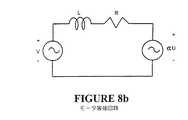
圧縮機モータの巻線へ印加される電圧を機械系の周波数に同期させる方法は周知のものである。自由ピストン圧縮機に用いられる永久磁石モータの場合、図8aに示すようにピストン速度に比例した逆起電力(逆EMF:back electromotive force)がモータの巻線に誘起される。図8bにモータの等価回路を示す。交流電圧(V)を交番起電力(alternating EMF)(αν)に同期して印可して、圧縮機に動力を供給する。米国特許第4,320,448号(Okuda外)は、モータの逆起電力のゼロクロスを検出して、印加電圧のタイミングを決定するという方法を開示している。モータ巻線への電圧の印加を調整して、起電力がゼロレベルを交差して逆起電力のゼロクロス検出ができる時点で電流がゼロになるようにする。
【0006】
2次気体ばね(secondary gas spring)、ピストン位置の検出、電流と印加電圧とに基づくピストン位置の計算(米国特許第5,496,153号)、周囲温度および/あるいは蒸発温度の測定(米国特許第4,179,899号と米国特許第4,283,920号)を始めとする様々な方法が、振動の振幅を制限するために用いられてきた。これらの方法には、センサを追加するためのコストがかかることや性能が制限されるといった問題点がある。
(発明の開示)
本発明の目的は、上記の問題点を克服するかあるいは少なくとも有用な選択肢を提供する小型リニアモータを提供することである。
【0007】
本発明の第1の態様によれば、往復動負荷(receprocating load)を駆動するための電気リニアモータは次の要素で構成される。すなわち、
少なくとも1個のエアギャップを備えた透磁性鉄心を有する固定子であって、一定でない磁束(non constant flux)をこの固定子と上記の少なくとも1個のエアギャップとに発生させる手段を有する固定子と、
永久磁石の少なくとも実質的な部分が上記の少なくとも1個のエアギャップの少なくとも1つ内に位置する少なくとも1個の上記永久磁石を支持する構造体を備えたアーマチュア(armature)であって、従って上記の少なくとも1個の永久磁石の磁界と上記の少なくとも1個のエアギャップ内の一定でない磁束との相互作用によって上記アーマチュアに力を発生し、使用時は上記負荷に接続され、それによって上記固定子に対して往復運動をするアーマチュアと、
上記の少なくとも1個の永久磁石の少なくとも一方の端部が、上記アーマチュアの往復運動の一部の間に上記の少なくとも1個のエアギャップの少なくとも1つ内に存在する略均一な磁束密度の領域の外側を通過するように、交番磁束を発生させる手段を制御するエネルギー供給手段(energisation means)と、により構成される。
【0008】
本発明の第2の態様によれば、冷蔵庫に圧縮機が用いられ、この圧縮機と圧縮機モータとがリニア装置であることを特徴とし、このモータは次の要素で構成される。すなわち、
少なくとも1個のエアギャップを設えた透磁性鉄心を有する固定子であって、一定でない磁束をこの固定子と上記の少なくとも1個のエアギャップとに発生させる手段を有する固定子と、
永久磁石の少なくとも実質的な部分が上記の少なくとも1個のエアギャップの中の少なくとも1つ内に位置する少なくとも1個の上記永久磁石を支持する構造体を備えたアーマチュアであって、従って上記の少なくとも1個の永久磁石の磁界と上記の少なくとも1個のエアギャップ内の一定でない磁束との相互作用によって上記アーマチュアに力を発生し、使用時は負荷に接続されて上記固定子に対して往復運動を行うアーマチュアと、
上記の少なくとも1個の永久磁石の少なくとも一方の端部が、前記アーマチュアの往復運動の一部の間に上記の少なくとも1個のエアギャップの少なくとも1つ内に存在する略均一な磁束密度の領域の外側を通過するように、交番磁束を発生させる手段を制御するエネルギー供給手段と、で構成される。
【0009】
本発明の第3の態様によれば、蒸気圧縮機は次の要素で構成される。すなわち、
ピストンと、
シリンダと、
上記シリンダ内で往復運動可能な上記ピストンとばねと、上記の蒸気の圧力によって変化する固有周波数を有する蒸気圧とから成る振動系と、
少なくとも1個の巻線を備えて上記ピストンに駆動可能に連結されたリニアブラシレス直流モータと、
直流電源と、
上記の少なくとも1個の巻線へ電流を供給して上記ピストンを往復運動させるために、上記直流電源から上記の少なくとも1個の巻線へ流れる電流を電子的に整流する整流手段(commutation means)と、
上記の少なくとも1個の巻線へ流れる電流の整流(commutation)を開始して上記ピストンを上記振動系の共振周波数で駆動する共振駆動手段(resonant driving means)と、
上記整流手段によって供給される電流の供給の量を決定する電流制御手段であって、上記の決定された電流の量は上記共振周波数に関連し、上記の少なくとも1個の巻線へ流れる電流の整流を開始して上記ピストンの往復運動の振幅を制限する電流制御手段と、により構成される。
【0010】
本発明の第4の態様によれば、自由ピストン蒸気圧縮機内のピストンを駆動し振幅を制御する方法が提供され、ここで、上記ピストンはシリンダ内で往復運動をし、このピストンとばねと蒸気圧とからなる振動系は蒸気圧によって変化する共振周波数を有する。上記方法は、少なくとも1個の巻線を備えたリニアブラシレス直流モータを用い、次のステップで構成される。すなわち、
直流電源から上記の少なくとも1個の巻線へ流れる電流を電子的に整流して上記ピストンを往復運動させるステップであって、ここで、上記整流は前記の振動系の共振周波数で上記ピストンを駆動するタイミングで行われるステップと、
上記共振周波数の関数である値に整流中に供給される電流を決定するパラメータ値を制限することによって、上記の少なくとも1個の巻線に流れる電流の量を制限するステップと、から成る。
【0011】
「圧縮機に入る蒸気の蒸発温度(evaporating temperature)」はまた、本明細書においては「蒸発器温度」と記す。同様に、「共振周波数」は「固有周波数」とも記す。
【0012】
本発明に関連する技術の当業者にとっては明白なように、本発明の構成の変更や大幅に異なる実施例や適用例が、特許請求の範囲に規定された本発明の範囲から逸脱しないで考えられるであろう。本明細書に記載の開示内容および記述については、単に例示的なものであり、いかなる意味でも限定を意図するものではない。
(発明の実施形態)
本発明は、先行技術に対する改良点を多数備えたリニアモータを制御する方法を提供する。第1の改良点は、米国特許第4,602,174号に記載の従来型のリニアモータに比べて寸法が小さい点であり、従って、低コストである。この変化にもかかわらず、低出力から中出力の場合は効率は依然として高い。ただし、高出力の場合やや効率が低下する。このことは、家庭用冷蔵庫は大抵の場合低出力から中出力の範囲で運転され、高出力で運転されるのは全運転時間の20%未満である(高出力で運転されるのは、頻繁に冷蔵庫の内容物の出し入れがある期間中や非常に暑い日に生ずる)ので、家庭用冷蔵庫の圧縮機としては許容できる妥協の範囲である。第2の改良点は、外部センサの必要性を無くし、従って寸法とコストとを低減しながら最適に効率の良い運転を可能にする制御手法を採用した点である。
【0013】
以下の記載では、本発明について円筒形リニアモータに関連づけて説明するが、本発明の方法は、一般的なリニアモータ、特にフラットリニアモータ(flat linear motor)にも同様に適用可能であることがわかる。当業者なら特別な努力なしで本明細書に記載の制御手法をどのような形態のリニアモータにも適用できるであろう。また、本発明はどのような形態の圧縮機にも適用可能である。自由ピストン圧縮機に関連づけて説明されるが、ダイアフラム型圧縮機(diaphragm compressor)にも同様に利用可能である。
【0014】
図1に示す本発明の実際的実施例は、往復運動をする自由ピストン圧縮機に接続される永久磁石リニアモータに係わる。シリンダ9は、圧縮機シェル30内においてシリンダばね14によって支持される。ピストン11は、シリンダ穴によって形成される軸受けに加えてそのばね13によってばね台(spring mount)25を介して半径方向に支持される。
【0015】
シリンダ9内のピストン11の往復運動によって、気体が吸引管12を経て吸引口26から吸引消音器(suction muffler)20を介して弁プレート21の吸引弁口24を通って圧縮空間28内に引抜かれる。圧縮された気体は、それから排出弁口(discharge valve port)23から排出され、排出消音器19内で消音され、排出管18を経て外へ出る。
【0016】
圧縮機モータは2個の部分固定子5と6とアーマチュア22とで構成される。ピストン11の往復運動を発生させる力は、(フランジ7でピストン11に装着された)アーマチュア22内の2個の環状の半径方向に磁化された永久磁石(annular radially magnetised permanent magnet)3、4の、エアギャップ33内の(固定子6とコイル1、2とによって誘起される)磁界との相互作用によって発生する。
【0017】
図1に示し、図2に分離して示す本発明の2つのコイルの実施例では、コイル1に電流が流れ、これが固定子6の内部に沿って軸方向に通る磁束を形成し、この磁束は、端部固定子歯部(end stator tooth)32から外側へ半径方向に通り、エアギャップ33を横断して鉄製背部5に入る。その後、磁束は、短い距離27だけ軸方向に通過した後、エアギャップ33を横断して半径方向に内側に通過し、固定子6の中央歯部34に戻る。第2コイル2によって発生した磁束は、エアギャップを横断して中央歯部34を経て半径方向に通過し、短い距離29の間軸方向に通り、エアギャップ33を経て外側に端部歯部35へと通過する。歯部32からエアギャップ33を横断した磁束は、磁石3の磁化が他方の磁石4に対して反対の極性のものである場合は半径方向に磁化された磁石3、4の上に軸方向の力を発生させる。鉄製背部5の代わりに、磁石の反対側にもう一組のコイルを設けても同じく可能であることがわかる。
【0018】
コイル1と2に流れる振動電流(oscillating current)は、必ずしも正弦波ではなく、磁石3と4上に振動力(oscillating force)を発生させ、その振動周波数が機械系の固有周波数に近ければ、この振動力によって磁石と固定子とにかなりの相対運動が生ずる。この固有周波数は、ばね13と14の剛性とシリンダ9と固定子6との質量とによって決定される。磁石3と4上の振動力は、固定子部分上に反作用力を発生させる。従って、接着、焼きばめ(shrink)あるいは締め具などによって、固定子6をシリンダ9にしっかり装着することが必要である。鉄製背部は、固定子台17に固定あるいは接着される。固定子台17はシリンダ9にしっかり結合される。
【0019】
図3に示す本発明の単一コイルの実施例では、コイル109に流れる電流によって、内部固定子110の内部に沿って軸方向に通る磁束が生成され、この磁束は、一方の歯部111を経て外側へ半径方向に通過し、磁石のギャップ112を横断し、鉄製背部115に入る。その後、磁束は、短い距離だけ軸方向に通過し、その後磁石のギャップ112を横断して内側の方へ半径方向に通過して、外側歯部116に入る。このモータの場合、磁石122全体が半径方向に磁化されて同一極性を有している。
【0020】
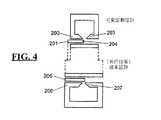
本発明の好適実施例の場合、アーマチュア(歯部)面の長さは、磁石の最大ストローク(磁石のエッジが最大出力時に伸びる長さ)の例えば67%までだけ伸びる。これは図4に見られ、いずれも最大ストロークで、従来の先行技術のリニアモータが等価な出力の本発明の可変定数設計(variable constant design)に対して見て分るように比較されている。図から分かるように、固定子の歯部の外側エッジ200は、磁石の外側端部201に達するほどまでは長くは伸びていない。同様に、他方の固定子の歯部の内側エッジ203は、磁石の内側端部204までは伸びていない。先行技術の設計では対照的に、磁石のエッジ205は、最大ストローク伸びたとき固定子の歯部のエッジ206と207に及ぶ。
【0021】
本発明ではストロークが例えば60%未満のとき、磁石70は、図5に示す領域aからbで示される均一磁束密度領域に存在するであろう。この領域は大体固定子の歯部71が伸びている範囲に一致する。ストロークが60%より増加するにつれて、磁石のエッジ70に生ずる磁束密度は、それが図5に示すエアギャップ磁界の外辺部(fringe portion)(非均一磁束密度部分)すなわちbの外側の領域に入るにつれて減少する。
【0022】
図7に示す更に別の実施例の場合、リニアモータの固定子は極面(pole face)503に角度がつけられて示されている。極面503の中心部でそれは平坦部500を有し、従って、エアギャップは略均一な磁束密度を有するその部分に面することになる。極面503の端部は角度がつけられて、磁束密度が中心部500の均一磁束密度から極面503の端部での外辺部502(非均一磁束密度部分)へとより漸進的に移行するようになっている。前述の実施例と同様に、アーマチュア磁石504は均一磁束密度領域500の外側に、非均一磁束密度の外辺部502へと駆動される。
【0023】
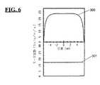
「モータ定数(Motor Constant)」を、モータ巻線に電流1アンペアを流した時に磁石上に発生する力(単位:ニュートン)として定義する。図6に示されているモータ定数曲線は、本発明に係わるモータ定数300が磁石の位置によって変化する様子を表す。同様に、「モータ定数」を、磁石が1メートル/秒で移動するときに発生する逆起電力(back EMF)(単位:ボルト)として定義することができる。磁石が外辺領域(fringe field)(図5のbの外側)にあるとき、電磁結合が減少するので、所与の力を発生させるには、磁石が均一磁束領域(図5のaからbまで)内にあるときより大きな電流を必要とすることになる。この結果、図6に示すように本発明の短固定子(short stator)リニアモータに係わる「可変」モータ定数曲線300のようになる。これは、やはり図6に示す従来の先行技術のリニアモータに固有の「一定(constant)」のモータ定数曲線301とは対照的である。
【0024】
図6に示すモータ定数曲線300から明らかなように、本発明のモータは、短ストロークと中ストローク(‐3mmから+3mmのストロークに相当する)では、等価な従来のモータ301(ターン数は少なくコア材料の体積は大きい)の場合より大きなモータ定数を有する。モータ定数がより大きいということは、(インバータ損失がより少ないので)より効率的な運転に相当するということであり、従って、出力が低い場合、本発明の方がそれと等価な従来の先行技術のリニアモータより効率がよい。また、本発明の方が必要なコアの横断面の面積も少ない。
【0025】
高ストロークでは、電流が最も迅速に増加するときは、モータ定数は小さくなる。このため、等価な従来の先行技術のリニアモータの場合に比べて最大ストロークではより大きな電流をモータに流し、従ってモータからより大きな動力を引き出すことが可能になる。また、最大ストロークで最小となるような可変定数を有する設計にすれば、モータをより効率良く方形波電圧で駆動できるようになる傾向を有する。
(制御手法)
自由ピストン圧縮機は、圧縮機ピストン−ばね系の固有周波数で駆動されるときに最も効率が良いことが実験的に立証されている。しかし、意図的に設けられる金属ばねのほかに固有の気体ばね(inherent gases spring)が存在し、気体ばねの有効ばね定数は、冷蔵庫用圧縮機の場合、蒸発器あるいは凝縮器の圧力が変化するにつれて変化する。先に述べた電子的に整流される永久磁石モータ(electronically commutated permanent magnet motor)は、その内容が参照されて本明細書に引用されている、例えば米国特許第4,857,814号およびWO98/35428にて開示されている電子整流型永久磁石モータにおける本出願人の経験から得られた技術を含む技術を用いて制御される。これらの参考文献に開示されているのは3相回転モータの制御であるが、同一の制御原理をリニアモータにも適用できる。適当なリニアモータは単相装置であることが求められ、また、モータに電力を供給する適当なインバータブリッジ回路は図9に示す単純な形態のものであってよい。
【0026】
モータ巻線における逆起電力のゼロクロスを監視することによって、電流の整流がピストンの固有周波数に追随するように決定することができる。単一の巻線しかないので、上側インバータスイッチング装置411かあるいは下側インバータスイッチング装置412を流れる電流は逆起電力を測定することができるように中断されなければならない。検出された逆起電力に従ってモータ巻線に流れる電流を制御することによって、電流と逆起電力とが確実に同位相の状態を保ち、システムの効率を最大にすることができる。
【0027】
モータの運転周波数は、周波数が逆起電力のゼロクロス間の時間の2倍の逆数であるとして、連続的に監視されるのが効果的である。しかも、WO98/35428によれば、整流が停止した後にフリーホイールダイオード413と414とを通る電流の減衰時間はモータ電流に正比例するので、モータ電流の測定が利用可能である。
【0028】
ピストンが圧縮機のシリンダヘッドに衝突しない範囲で用いることができる最大モータ電流は、蒸発器温度(evaporator temperature)と振動系の固有周波数とに依存して変化する。
【0029】
図10は、最大許容モータ電流を機械系の固有周波数と凝縮器温度(condenser temperature)とに対して様々な蒸発温度の場合について示したグラフである。これらのグラフは、最大モータ電流のこれらの2つの変数に対する依存性を示している。これらはまた、凝縮器温度は機械系の周波数に比例し、最大電流制御は従って第3の変数すなわち凝縮器温度の測定を必要とせずに達成可能であることを示している。
【0030】
本発明に係わるモータ制御回路を図11に示す。これは、機械系の周波数は凝縮器温度に関連するという観測結果を利用したものである。本発明によれば、モータ巻線1に誘起される逆起電力信号(EMF signal)は回路402によって検知されてデジタル化され、マイクロコンピュータ403の入力に与えられる。マイクロコンピュータ403は、モータ巻線へ流れる電流の整流(commutation)のための適切なタイミングを演算して、電流が確実に逆起電力と同相になるようにする。この整流タイミング信号がモータ巻線401へ電流を供給するインバータ404(図11に示すように)のスイッチングを行なう。マイクロコンピュータ403は、また、逆起電力のゼロクロス間の時間を測定し、これによって、起電力(EMF)波形の周期を測定する。機械系の固有振動周波数は起電力波形の周期(period)の逆関数である。従ってマイクロコンピュータ403は常にこの周波数を測定する。
【0031】
蒸発器温度を測定して霜を除去する目的のためには従来の温度センサ405を使用し、また、その出力は、デジタル化されてマイクロコンピュータ403への更なる入力として供給される。
【0032】
本発明によれば、最大モータ電流を制限し、従ってピストンの最大変位を制限する1つの方法は、マイクロコンピュータ403でピストンの振動の各半周期毎に最大電流振幅を算出して実際の電流振幅を上記の最大値未満に制限するというものである。WO98/35428には、電力が供給されていない巻線(unpowered winding)における逆起電力のデジタル信号を利用して電子整流型永久磁石モータに流れるモータ電流を測定して、モータ巻線の電流が減衰してゼロになるまでの所要時間を測定する方法が開示されている。この方法を本発明に使用することによって、マイクロコンピュータ403によって、専用の電流検知/制限回路を必要とせずに最高出力を制限することが可能となる。RMSモータ電流は、付随するインバータスイッチング装置がスイッチオフされた後に「フリーホイーリング(freewheeling)」ダイオード413か414を通って流れる電流の減衰の継続期間に正比例する。この電流減衰は、言うまでもなく、モータ巻線が、整流中にエネルギーを蓄積し、整流停止後それを放出するリアクトル(inductor)であることによって結果的に引起されるものである。RMSモータ電流対電流減衰期間のグラフ(WO98/35428中の図6を簡単にしたもの)を図12に示す。
【0033】
別の好適な方法は、最大電流値を制限する代わりに電流が整流される時間を制限するというものである。図15は、このように制御された電流の波形を示す。要するに、これは、整流間隔当り1つだけの変調された電流パルスを有するパルス幅変調(PWM)である。この方法によれば、逆起電力のゼロクロスからの遅れ時間(delay time)を演算してモータ電流と逆起電力との間の位相角を最小にして効率が最大になるようにする。モータの半サイクル中のある時点で電流供給インバータスイッチをオフにして、電流減衰期間(current decay period)後に逆起電力のゼロクロスを監視して、次の半サイクルに対する整流の開始(start commutation)を決定することができるようにする。整流時間は、モータ周波数と蒸発器温度に対して適切な最大整流時間と比較されて、確実にピストンストロークの最大振幅を上回らないようにする。
【0034】
上記の方法を実行するためのマイクロコンピュータ制御手法の流れ図を図13と14に示す。図13を参照すると、まず最初に圧縮機に電力が供給されて(421)、あるいは、冷蔵システムにおいて圧力が確実に等しくなるようにするための十分な時間遅れの後に電力が供給されて、圧縮機は最低周波数で運転する。この最低周波数のストローク周期(stroke period)は運転_ストローク(Run_Stroke)として測定され、低_ストローク(Low_Stroke)としてマイクロコンピュータに記述され、また、最小整流時間がこの値に対して設定される(428)。各つぎのストロークに対して、そのストローク周期が測定されて運転_ストロークというパラメータとして規定される(424)。運転_ストロークと低_ストロークとの間の差異が演算される(図14の431)。この差異を周期_インデックス(Period_Index)と呼ぶ。この周期_インデックスはこのサブルーチンでは、異なるストローク時間(周波数(frequency))に対する最大整流時間のルックアップテーブル内のインデックスポインタとして使用される。このテーブルはパルス_リミット_値テーブル(Pulse_Limit_Vatue Table)と呼ばれる。ここでは、7つの蒸発温度範囲(440〜465)に対応する7つのルックアップテーブル(433〜439)がある。
【0035】
モータ制御回路は、普通従来通り温度制御ループ内に含まれ、冷蔵システムの囲まれた冷蔵空間の温度を維持する。この制御ループは、冷蔵システムの運転条件に従ってモータ巻線に供給されるべき電力に対する所望値を設定することになる。この所望電力値は、整流時間値に対応するであろう。ストローク毎にこの整流時間値はパルス_リミット_値と比較される(図14の440)。整流時間の所望値がパルス_リミット_値より大きい場合は、整流時間はそのパルス_リミット_値に制限される。この値は関連のインバータスイッチング装置のオン期間を制御する整流タイマをセットする(425)。前に述べたように、モータ電流も同様にモータに供給される電力を安全レベルに制限するために使用できるが、整流時間が制御されている場合でも、モータ電流を前述のように測定して格納されている絶対最大値とを比較し(426)、その絶対最大値を超えた場合、マイクロコンピュータのプログラムをリセットさせる(427)ことが望ましい。
【0036】
当然のことながら、最大整流時間および/あるいは最大電流値を決定する方法で実現可能な方法は他にもある。例えば、マイクロコンピュータが、例えば、DSPチップ技術の最近の進歩のように十分に強力ならば、ルックアップテーブルがなくてもこれらの値を直接演算することができる。
【0037】
図9のインバータブリッジに印可される直流電源電圧が顕著に変動する場合、考慮されるべき所与の整流時間の間のモータ電流も結果的に変動する。マイクロプロセッサが最大の精度でこの変動を検知し補償することが望ましい。
【0038】
本発明を冷蔵庫で使用すれば、従来設計のものに比べて、モータの輪郭と寸法と重さとを低減できることが認識されよう。また、可動部分の質量が従来の冷蔵庫圧縮機の質量より少ないので、
・振動レベルが低下し、
・ノイズレベルが低下し、
・可動部分にかかる作用応力(working stress)が低下する。
【図面の簡単な説明】
【図1】 本発明に係わるリニア圧縮機の断面図である。
【図2】 本発明の2重コイルリニアモータを分離して示す断面図である。
【図3】 単一コイルリニアモータの断面図である。
【図4】 従来技術の単一ウインドウリニアモータと本発明に係わる短固定子リニアモータとの比較を示す図である。
【図5】 本発明の単一コイルリニアモータにおけるコイル電流による磁束線を表す図である。
【図6】 本発明の好適実施例に関するモータ定数対磁石位置のグラフを示す図である。
【図7】 部分的に角度をつけた磁極面をもつ単一コイルリニアモータの断面図である。
【図8a】 自由ピストン圧縮機モータに関するモータピストン変位と逆起電力(EMF)とを表す波形を示す図である。
【図8b】 上記モータの等価回路を示す図である。
【図9】 単相自由ピストンモータの電流を電子的に整流するためのインバータを示す図である。
【図10】 本発明のモータに関する周波数と蒸発温度との関数としての最大モータ電流のグラフを示す図である。
【図11】 モータ制御回路のブロック図である。
【図12】 モータ電流(RMS)対モータ巻線電流減衰時間のグラフを示す図である。
【図13】 モータ制御タイミングプログラムの流れ図である。
【図14】 蒸発温度とストローク時間のデータを用いた整流時間決定の流れ図である。
【図15】 モータピストン変位とモータ電流とを表す波形を示す図である。[0001]
(Technical field)
The present invention relates to a small linear motor with a free piston compressor (also referred to as a vibrating and linear compressor) for a vapor compression system, and in particular, a desirable compression level caused by changes in ambient temperature or operating conditions. The present invention relates to a control system for preventing failure or damage due to no change.
(Background technology)
A compressor, such as a refrigerator compressor, is conventionally driven by a rotary electric motor. However, even the most efficient form has significant losses associated with a crank system that converts rotational motion to linear reciprocating motion. Alternatively, a rotary compressor that does not require a crank can be used, but again the friction loss is significant due to the high centripetal load. In the case of a linear compressor driven by a linear motor, these losses do not occur, and an aerostatic gas bearing can be used as disclosed in US Pat. No. 5,525,845. The bearing load can be designed low enough.
[0002]
A linear reciprocating motor does not require a crank mechanism that produces a high side force that requires oil lubrication, which is characteristic of a compressor where power is provided by a rotating electric motor. This type of motor is described in U.S. Pat. No. 4,602,174. U.S. Pat. No. 4,602,174 discloses a very efficient linear motor design in terms of both reciprocating mass and electrical efficiency. This design has been successfully applied to motors and alternators that utilize a stirling cycle. It has also been used as a motor for linear compressors. However, in the case of a compressor designed for a home refrigerator, the design described in US Pat. No. 4,602,174 is slightly larger and more costly than desired in this market.
[0003]
The piston of a free piston compressor oscillates as a resonant system in combination with a spring and is inherent in the vibration amplitude, except for collisions with stationary parts, typically cylinder head assembly parts. There is no limit. This piston takes an average position and amplitude depending on the gas force and the input power. Thus, for any given input power, as either the evaporating pressure or the condensing pressure decreases, the vibration amplitude increases until a collision occurs. It is therefore necessary to limit the power as a function of these pressures.
[0004]
In order to maximize efficiency, it is desirable to operate the free piston refrigeration compressor at the natural frequency of the mechanical system. This frequency is determined by the spring constant and the mass of the mechanical system, and is also determined by the elasticity coefficient of the gas. In the case of refrigeration, the elastic modulus of the gas increases with both evaporation pressure and condensation pressure. Therefore, the natural frequency also increases. In order to operate in the best condition, the frequency of the electric system that supplies electric power to the compressor is required to be changed in accordance with the frequency of the mechanical system that changes according to the operating conditions.
[0005]
Methods for synchronizing the voltage applied to the compressor motor windings with the frequency of the mechanical system are well known. In the case of a permanent magnet motor used in a free piston compressor, a back electromotive force (back EMF) proportional to the piston speed is induced in the motor winding as shown in FIG. 8a. Fig. 8b shows the equivalent circuit of the motor. An AC voltage (V) is applied in synchronism with alternating electromotive force (alternating EMF) (αν) to supply power to the compressor. U.S. Pat. No. 4,320,448 (Okuda et al.) Discloses a method for detecting the zero crossing of the back electromotive force of the motor and determining the timing of the applied voltage. The application of voltage to the motor winding is adjusted so that the current becomes zero when the electromotive force crosses the zero level and zero cross detection of the counter electromotive force can be detected.
[0006]
Secondary gas spring, detection of piston position, calculation of piston position based on current and applied voltage (US Pat. No. 5,496,153), measurement of ambient temperature and / or evaporation temperature (US Pat. No. 4,179,899) Various methods have been used to limit the amplitude of vibration, including US Pat. No. 4,283,920). These methods have problems such as high cost for adding sensors and limited performance.
(Disclosure of the Invention)
It is an object of the present invention to provide a compact linear motor that overcomes the above problems or at least provides a useful option.
[0007]
According to the first aspect of the present invention, an electric linear motor for driving a receprocating load is composed of the following elements. That is,
Stator having a magnetically permeable core with at least one air gap, the stator having means for generating a non-constant flux in the stator and the at least one air gap When,
An armature comprising a structure supporting at least one of said permanent magnets, wherein at least a substantial part of said permanent magnet is located within at least one of said at least one air gap, The armature generates a force by the interaction of the magnetic field of the at least one permanent magnet with the non-constant magnetic flux in the at least one air gap and is connected to the load when in use, thereby the stator An armature that reciprocates against
A region of substantially uniform magnetic flux density in which at least one end of the at least one permanent magnet exists within at least one of the at least one air gap during a portion of the armature's reciprocating motion. Energy supply means (energisation means) for controlling the means for generating the alternating magnetic flux so as to pass outside.
[0008]
According to the second aspect of the present invention, a compressor is used in the refrigerator, and the compressor and the compressor motor are linear devices, and the motor includes the following elements. That is,
A stator having a magnetically permeable iron core with at least one air gap, the stator having means for generating a non-constant magnetic flux in the stator and the at least one air gap;
An armature comprising a structure supporting at least one of said permanent magnets, wherein at least a substantial part of said permanent magnet is located in at least one of said at least one air gap, A force is generated in the armature by the interaction of the magnetic field of at least one permanent magnet and the non-constant magnetic flux in the at least one air gap, and when used, it is connected to a load and reciprocates with respect to the stator. An armature doing exercise,
A region of substantially uniform magnetic flux density where at least one end of the at least one permanent magnet is present in at least one of the at least one air gap during a portion of the armature's reciprocating motion. Energy supply means for controlling the means for generating the alternating magnetic flux so as to pass outside.
[0009]
According to the third aspect of the present invention, the steam compressor is composed of the following elements. That is,
A piston,
A cylinder,
A vibration system comprising the piston and a spring that can reciprocate in the cylinder, and a vapor pressure having a natural frequency that varies with the pressure of the vapor;
A linear brushless DC motor comprising at least one winding and drivably coupled to the piston;
DC power supply,
Commutation means for electronically rectifying the current flowing from the DC power source to the at least one winding to supply current to the at least one winding to reciprocate the piston. When,
Resonant driving means for starting commutation of the current flowing through the at least one winding and driving the piston at the resonance frequency of the vibration system;
Current control means for determining the amount of current supplied by the rectifying means, the determined amount of current being related to the resonance frequency and of the current flowing through the at least one winding; Current control means for starting rectification and limiting the amplitude of the reciprocating motion of the piston.
[0010]
According to a fourth aspect of the present invention, there is provided a method for driving and controlling the amplitude of a piston in a free piston steam compressor, wherein the piston reciprocates in a cylinder, the piston, spring and steam. The vibration system composed of pressure has a resonance frequency that varies depending on the vapor pressure. The above method uses a linear brushless DC motor having at least one winding and is composed of the following steps. That is,
Electronically rectifying the current flowing from the DC power source to the at least one winding to reciprocate the piston, wherein the rectification drives the piston at a resonance frequency of the vibration system. Steps performed at the timing of
Limiting the amount of current flowing in the at least one winding by limiting a parameter value that determines the current supplied during rectification to a value that is a function of the resonant frequency.
[0011]
“Evaporating temperature of vapor entering the compressor” is also referred to herein as “evaporator temperature”. Similarly, “resonance frequency” is also referred to as “natural frequency”.
[0012]
It will be apparent to those skilled in the art to which the present invention pertains that changes in configuration and / or significantly different embodiments and applications of the invention are contemplated without departing from the scope of the invention as defined in the claims. Will be done. The disclosures and descriptions in this specification are merely exemplary and are not intended to be in any sense limiting.
(Embodiment of the Invention)
The present invention provides a method for controlling a linear motor with many improvements over the prior art. The first improvement is that the dimensions are small compared to the conventional linear motor described in U.S. Pat. No. 4,602,174, and therefore low cost. Despite this change, efficiency is still high for low to medium power. However, the efficiency is slightly reduced in the case of high output. This means that home refrigerators are usually operated in the low to medium power range, and are operating at high power for less than 20% of the total operating time (high power is often This is an acceptable compromise for household refrigerator compressors. The second improvement is the use of a control technique that eliminates the need for external sensors and thus enables optimally efficient operation while reducing size and cost.
[0013]
In the following description, the present invention will be described in relation to a cylindrical linear motor, but the method of the present invention may be equally applicable to general linear motors, particularly flat linear motors. Recognize. Those skilled in the art will be able to apply the control techniques described herein to any form of linear motor without special effort. The present invention can be applied to any type of compressor. Although described in connection with a free piston compressor, it is equally applicable to a diaphragm compressor.
[0014]
The practical embodiment of the present invention shown in FIG. 1 relates to a permanent magnet linear motor connected to a reciprocating free piston compressor. The cylinder 9 is supported by a
[0015]
By reciprocating movement of the
[0016]
The compressor motor is composed of two
[0017]
In the two-coil embodiment of the invention shown in FIG. 1 and separated in FIG. 2, a current flows through coil 1, which forms a magnetic flux that passes axially along the interior of the
[0018]
The oscillating current flowing in the
[0019]
In the single-coil embodiment of the present invention shown in FIG. 3, the current flowing through the
[0020]
In the preferred embodiment of the present invention, the length of the armature (tooth) surface extends, for example, up to 67% of the maximum stroke of the magnet (the length that the edge of the magnet extends at maximum output). This can be seen in FIG. 4, both at maximum stroke, compared so that a conventional prior art linear motor can be seen against the variable constant design of the present invention with an equivalent output. . As can be seen, the
[0021]
In the present invention, when the stroke is, for example, less than 60%, the
[0022]
In yet another embodiment shown in FIG. 7, the stator of the linear motor is shown angled on a
[0023]
“Motor Constant” is defined as the force (unit: Newton) generated on the magnet when a current of 1 ampere flows through the motor winding. The motor constant curve shown in FIG. 6 shows how the motor constant 300 according to the present invention changes depending on the position of the magnet. Similarly, the “motor constant” can be defined as the back electromotive force (back EMF) (unit: volts) generated when the magnet moves at 1 meter / second. When the magnet is in the fringe field (outside b in FIG. 5), the electromagnetic coupling is reduced, so that to generate a given force, the magnet is in a uniform flux region (a to b in FIG. 5). Will require a larger current than This results in a “variable” motor
[0024]
As is apparent from the motor
[0025]
At high stroke, the motor constant decreases when the current increases most rapidly. This allows a larger current to flow through the motor at the maximum stroke than in the case of equivalent prior art linear motors, thus allowing more power to be drawn from the motor. Further, if the design has a variable constant that is minimized at the maximum stroke, the motor tends to be driven with a square wave voltage more efficiently.
(Control method)
Free piston compressors have been experimentally proven to be most efficient when driven at the natural frequency of the compressor piston-spring system. However, in addition to the intentionally provided metal spring, there is an inherent gas spring, and the effective spring constant of the gas spring changes the pressure of the evaporator or condenser in the case of a refrigerator compressor. Change as you go. The previously described electronically commutated permanent magnet motor is disclosed in, for example, US Pat. No. 4,857,814 and WO98 / 35428, the contents of which are incorporated herein by reference. It is controlled using techniques including those obtained from the applicant's experience with electronic commutated permanent magnet motors. Although these references disclose control of a three-phase rotary motor, the same control principle can be applied to a linear motor. A suitable linear motor is required to be a single phase device, and a suitable inverter bridge circuit for supplying power to the motor may be of the simple form shown in FIG.
[0026]
By monitoring the zero crossing of the back electromotive force in the motor winding, it can be determined that the current commutation follows the natural frequency of the piston. Since there is only a single winding, the current flowing through the upper
[0027]
It is effective to continuously monitor the motor operating frequency, assuming that the frequency is a reciprocal of twice the time between zero crossings of the counter electromotive force. Moreover, according to WO98 / 35428, since the decay time of the current passing through the
[0028]
The maximum motor current that can be used as long as the piston does not collide with the cylinder head of the compressor varies depending on the evaporator temperature and the natural frequency of the vibration system.
[0029]
FIG. 10 is a graph showing the maximum allowable motor current for various evaporating temperatures versus the natural frequency of the mechanical system and the condenser temperature. These graphs show the dependence of the maximum motor current on these two variables. They also show that the condenser temperature is proportional to the frequency of the mechanical system and that maximum current control can therefore be achieved without the need to measure the third variable, namely the condenser temperature.
[0030]
A motor control circuit according to the present invention is shown in FIG. This is based on the observation that the frequency of the mechanical system is related to the condenser temperature. According to the present invention, a back electromotive force signal (EMF signal) induced in the motor winding 1 is detected and digitized by the
[0031]
A
[0032]
According to the present invention, one method of limiting the maximum motor current and thus limiting the maximum displacement of the piston is to calculate the maximum current amplitude for each half cycle of the piston vibration in the
[0033]
Another preferred method is to limit the time that the current is rectified instead of limiting the maximum current value. FIG. 15 shows the waveform of the current thus controlled. In short, this is a pulse width modulation (PWM) with only one modulated current pulse per commutation interval. According to this method, the delay time from the zero cross of the back electromotive force is calculated to minimize the phase angle between the motor current and the back electromotive force so as to maximize the efficiency. At some point during the motor's half cycle, the current supply inverter switch is turned off, and after the current decay period, the zero-crossing of the back electromotive force is monitored to start commutation for the next half cycle. To be able to decide. The commutation time is compared to the maximum commutation time appropriate for the motor frequency and evaporator temperature to ensure that the maximum amplitude of the piston stroke is not exceeded.
[0034]
Flow charts of microcomputer control techniques for implementing the above method are shown in FIGS. Referring to FIG. 13, the compressor is initially powered (421), or after a sufficient time delay to ensure that the pressure is equal in the refrigeration system, and compressed. The machine operates at the lowest frequency. This lowest frequency stroke period is measured as Run_Stroke, described in the microcomputer as Low_Stroke, and a minimum commutation time is set for this value (428 ). For each subsequent stroke, the stroke period is measured and defined as a parameter of operation_stroke (424). The difference between the operation_stroke and the low_stroke is calculated (431 in FIG. 14). This difference is called a period_index. This period_index is used in this subroutine as an index pointer in a look-up table of maximum commutation times for different stroke times (frequency). This table is called a Pulse_Limit_Vatue Table. Here, there are seven look-up tables (433-439) corresponding to seven evaporation temperature ranges (440-465).
[0035]
The motor control circuit is normally included in the temperature control loop as usual to maintain the temperature of the refrigerated space enclosed by the refrigeration system. This control loop will set the desired value for the power to be supplied to the motor windings according to the operating conditions of the refrigeration system. This desired power value will correspond to the commutation time value. This commutation time value is compared with the pulse_limit_value for each stroke (440 in FIG. 14). If the desired value of commutation time is greater than the pulse_limit_value, the commutation time is limited to that pulse_limit_value. This value sets (425) the commutation timer that controls the on period of the associated inverter switching device. As mentioned earlier, motor current can be used to limit the power supplied to the motor to a safe level as well, but even when the commutation time is controlled, the motor current is measured as described above. The stored absolute maximum value is compared (426), and if the absolute maximum value is exceeded, the microcomputer program is preferably reset (427).
[0036]
Of course, there are other methods that can be implemented by determining the maximum commutation time and / or the maximum current value. For example, if a microcomputer is powerful enough, for example, as recent advances in DSP chip technology, these values can be directly computed without a lookup table.
[0037]
If the DC power supply voltage applied to the inverter bridge of FIG. 9 varies significantly, the motor current during a given commutation time to be considered will also vary. It is desirable for the microprocessor to detect and compensate for this variation with maximum accuracy.
[0038]
It will be appreciated that the present invention can be used in a refrigerator to reduce the motor outline, dimensions and weight compared to conventional designs. Also, since the mass of the movable part is less than the mass of the conventional refrigerator compressor,
・ Vibration level decreases,
・ Noise level decreases,
-The working stress on the movable part is reduced.
[Brief description of the drawings]
FIG. 1 is a cross-sectional view of a linear compressor according to the present invention.
FIG. 2 is a sectional view showing a double coil linear motor of the present invention separately.
FIG. 3 is a cross-sectional view of a single coil linear motor.
FIG. 4 shows a comparison between a prior art single window linear motor and a short stator linear motor according to the present invention.
FIG. 5 is a diagram showing magnetic flux lines due to a coil current in the single coil linear motor of the present invention.
FIG. 6 is a graph of motor constant versus magnet position for a preferred embodiment of the present invention.
FIG. 7 is a cross-sectional view of a single coil linear motor having a partially angled pole face.
FIG. 8a is a diagram showing waveforms representing motor piston displacement and back electromotive force (EMF) for a free piston compressor motor.
FIG. 8b is a diagram showing an equivalent circuit of the motor.
FIG. 9 is a diagram showing an inverter for electronically rectifying a current of a single-phase free piston motor.
FIG. 10 shows a graph of maximum motor current as a function of frequency and evaporation temperature for the motor of the present invention.
FIG. 11 is a block diagram of a motor control circuit.
FIG. 12 is a graph showing motor current (RMS) versus motor winding current decay time.
FIG. 13 is a flowchart of a motor control timing program.
FIG. 14 is a flowchart for determining a rectification time using evaporation temperature and stroke time data.
FIG. 15 is a diagram showing waveforms representing motor piston displacement and motor current.
Claims (28)
Translated fromJapanese少なくとも1個のエアギャップを備えた透磁性鉄心を有する固定子であって、一定でない磁束を前記固定子と前記少なくとも1個のエアギャップ内に発生させるための手段を有する固定子と、
少なくとも実質的な部分が前記少なくとも1個のエアギャップの少なくとも1個内に配置される少なくとも1個の永久磁石を支持する構造体を有するアーマチュアであって、従って前記少なくとも1個の永久磁石の磁界と前記少なくとも1個のエアギャップ内の前記一定でない磁束との相互作用によって前記アーマチュア上に力が加わり、使用時には前記負荷に連結され、それによって前記固定子に対して往復運動をするアーマチュアと、
前記少なくとも1個の永久磁石の少なくとも一方の端部が、前記アーマチュアの往復運動の一部の間に前記少なくとも1個のエアギャップの前記少なくとも1個内に存在する略均一な磁束密度の領域の外側を通過するように、交番磁束を発生させる手段を制御するためのエネルギー供給手段と
を含む電気リニアモータ。An electric linear motor for driving a reciprocating load,
A stator having a permeable iron core with at least one air gap, the stator having means for generating a non-constant magnetic flux in the at least one air gap; and
An armature having a structure supporting at least one permanent magnet, at least a substantial part of which is disposed within at least one of said at least one air gap, and thus the magnetic field of said at least one permanent magnet And an armature that exerts a force on the armature by interaction with the non-constant magnetic flux in the at least one air gap and is coupled to the load in use, thereby reciprocating relative to the stator;
At least one end of the at least one permanent magnet is in a region of substantially uniform magnetic flux density that exists within the at least one of the at least one air gap during a portion of the armature reciprocation. An electric linear motor comprising: energy supply means for controlling means for generating an alternating magnetic flux so as to pass outside.
少なくとも1個のエアギャップを備えた透磁性鉄心を有する固定子であって、一定でない磁束を前記固定子と前記少なくとも1個のエアギャップ内に発生させる手段を有する固定子と、
少なくとも実質的な部分が前記少なくとも1個のエアギャップの少なくとも1個内に配置される少なくとも1個の永久磁石を支持する構造体を有するアーマチュアであって、従って前記少なくとも1個の永久磁石の磁界と前記少なくとも1個のエアギャップ内の前記一定でない磁束との相互作用によって前記アーマチュア上に力が加わり、使用時には負荷に接続され、それによって前記固定子に対して往復運動をするアーマチュアと、
前記少なくとも1個の永久磁石の少なくとも一方の端部が、前記アーマチュアの往復運動の一部中に前記少なくとも1個のエアギャップの少なくとも1個内に存在する略均一な磁束密度の領域の外側を通過するように、交番磁束を発生させるための手段を制御するエネルギー供給手段と、
を含む冷蔵庫。A refrigerator using a compressor, wherein the compressor and the compressor motor are linear devices, wherein the motor is
A stator having a permeable iron core with at least one air gap, the stator having means for generating a non-constant magnetic flux in the at least one air gap; and
An armature having a structure supporting at least one permanent magnet, at least a substantial part of which is disposed within at least one of said at least one air gap, and thus the magnetic field of said at least one permanent magnet And an armature that exerts a force on the armature by interaction with the non-constant magnetic flux in the at least one air gap and is connected to a load in use, thereby reciprocating relative to the stator;
At least one end of the at least one permanent magnet is outside a region of substantially uniform magnetic flux density that is present in at least one of the at least one air gap during a portion of the armature's reciprocating motion. Energy supply means for controlling the means for generating alternating magnetic flux to pass through;
Including refrigerator.
シリンダと、
前記シリンダ内で往復運動可能な前記ピストンとばねと、蒸気圧と共に変化する固有周波数を有する前記蒸気圧の振動系と、
少なくとも1個の巻線を有する、前記ピストンに駆動可能に連結されるリニアブラシレス直流モータと、
直流電源と、
前記直流電源から前記少なくとも1個の巻線に流れる電流を電子的に整流して前記少なくとも1個の巻線へ電流を供給して、前記ピストンを往復運動させる整流手段と、
前記少なくとも1個の巻線に流れる電流の整流を開始することによって前記振動系の共振周波数で前記ピストンを駆動する共振駆動手段と、
前記整流手段によって供給される前記の電流の供給の量を決める電流制御手段であって、前記決定された電流の量は前記共振周波数に関連し、また、前記少なくとも1個の巻線に流れる電流の整流を開始することによって前記ピストンの往復運動の振幅を制限する電流制御手段と、
を含む蒸気圧縮機。A piston,
A cylinder,
The piston and spring capable of reciprocating in the cylinder; and a vibration system of the vapor pressure having a natural frequency that varies with the vapor pressure;
A linear brushless DC motor drivably coupled to the piston having at least one winding;
DC power supply,
Rectifying means for reciprocating the piston by electronically rectifying current flowing from the DC power source to the at least one winding to supply current to the at least one winding;
Resonance driving means for driving the piston at a resonance frequency of the vibration system by starting rectification of the current flowing in the at least one winding;
Current control means for determining the amount of supply of the current supplied by the rectifying means, the determined amount of current being related to the resonant frequency and current flowing in the at least one winding; Current control means for limiting the amplitude of reciprocation of the piston by initiating rectification of
Including steam compressor.
前記決定された電流の量はまた前記の測定された指標特性に関連している請求項6に記載の蒸気圧縮機。And a sensor for measuring a characteristic of the steam entering the compressor that is indicative of the pressure, wherein
The steam compressor of claim 6, wherein the determined amount of current is also related to the measured indicator characteristic.
整流電流が流れないときに前記少なくとも1個の巻線に誘起される逆起電力をサンプリングして、逆起電力ゼロクロスを検出することから導かれるタイミング信号を生成する逆起電力検出手段と、
前記ゼロクロスのタイミング信号に応じて前記少なくとも1個の巻線に流れる電流の整流を開始することによって前記振動系の共振周波数で前記ピストンを駆動する共振整流手段と、
を含む請求項6〜8のいずれか1項に記載の蒸気圧縮機。The resonance driving means includes
Back electromotive force detection means for sampling a back electromotive force induced in the at least one winding when no rectified current flows, and generating a timing signal derived from detecting a back electromotive force zero cross;
Resonance rectification means for driving the piston at a resonance frequency of the vibration system by starting rectification of the current flowing in the at least one winding in response to the zero-cross timing signal;
The steam compressor according to any one of claims 6 to 8, comprising:
前記の測定された電流が前記の決定された電流の量に達したときに、前記電流制御手段は整流を終了させる請求項9に記載の蒸気圧縮機。And further comprising current sensing means for measuring the current flowing through the at least one winding during rectification, wherein
10. The steam compressor according to claim 9, wherein the current control means terminates commutation when the measured current reaches the determined amount of current.
メモリと入出力ポートとを含むプログラムされたデジタルプロセッサであって、第1のポートが前記逆起電力検出手段の出力に接続され、第2のポート群が前記整流手段に接続されてスイッチング制御信号を前記第2ポート群に供給するディジタルプロセッサと、
前記メモリに記憶されて、前記プロセッサが前記逆起電力のゼロクロス間の間隔に基づいてモータ電流の基準を決定するようにさせるソフトウェアであって、
前記間隔は、電流の供給が前記少なくとも1個の巻線から除去された後に前記一方向電流装置による前記蓄積されたエネルギーの放出によって前記少なくとも1個の巻線に生成される電流パルスの継続期間を表すソフトウェアと、
を含む請求項10に記載の蒸気圧縮機。The rectifying means is connected to the DC power source and supplies a current to the at least one winding, and is stored in each winding after the supply of current through one switching device is finished. A one-way current device for providing a current path for discharging the energy, the current detection means,
A programmed digital processor including a memory and an input / output port, wherein a first port is connected to the output of the back electromotive force detection means, and a second port group is connected to the rectification means to switch the control signal A digital processor for supplying the second port group;
Software stored in the memory for causing the processor to determine a reference for a motor current based on an interval between zero crossings of the back electromotive force,
The interval is a duration of a current pulse generated in the at least one winding by release of the stored energy by the one-way current device after a current supply is removed from the at least one winding. Software representing
The steam compressor according to claim 10, comprising:
前記共振周波数を測定する手段と、
前記振動系に対する複数の共振周波数の各々の値に対する最大電流整流値を含むルックアップテーブルを少なくとも1個格納するメモリと、
前記の測定された共振周波数に対応する前記テーブルの値を選択して該値を前記整流制御手段へ供給する値選択手段と、
を含む請求項6〜11のいずれか1項に記載の蒸気圧縮機。The current control means further includes:
Means for measuring the resonant frequency;
A memory storing at least one lookup table including a maximum current rectification value for each value of a plurality of resonance frequencies for the vibration system;
Value selection means for selecting a value of the table corresponding to the measured resonance frequency and supplying the value to the rectification control means;
The steam compressor according to claim 6, comprising:
前記共振周波数を測定する手段と、
前記振動系に対する複数の共振周波数の値に対する最大電流整流値を含むメモリに格納された複数のルックアップテーブルを格納する前記メモリであって、前記の各ルックアップテーブルは前記指標特性の重複しない範囲に対応するメモリと、
前記指標特性の測定された値に基づいて使用するために前記ルックアップテーブルを選択するテーブル選択手段と、
前記の測定された共振周波数に対応する前記テーブル内の値を選択して前記整流制御手段へ該値を供給する値選択手段と、
を含む請求項7または8に記載の蒸気圧縮機。The current control means further includes:
Means for measuring the resonant frequency;
The memory for storing a plurality of lookup tables stored in a memory including a maximum current rectified value for a plurality of resonance frequency values for the vibration system, wherein each of the lookup tables is a range in which the index characteristics do not overlap. Memory corresponding to
Table selection means for selecting the lookup table for use based on a measured value of the indicator characteristic;
Value selection means for selecting a value in the table corresponding to the measured resonance frequency and supplying the value to the rectification control means;
The steam compressor according to claim 7 or 8, comprising:
直流電源から前記少なくとも1個の巻線へ流れる電流を電子的に整流して前記ピストンを往復運動させるステップであって、前記ピストンを前記振動系の前記共振周波数で駆動するようなタイミングに合わせて整流を行うステップと、前記共振周波数の関数である値に整流中の電流の供給を決定するパラメータ値を制限することによって前記少なくとも1個の巻線に流れる電流の量を制限するステップと、
を含む方法。A method of controlling the amplitude by driving a piston of a free piston steam compressor, wherein the piston reciprocates in a cylinder, and a vibration system of the piston, the spring, and the pressure of the steam is combined with the steam pressure. In a method using a linear brushless DC motor having a varying resonant frequency and having at least one winding,
A step of electronically rectifying a current flowing from the DC power source to the at least one winding to reciprocate the piston in accordance with a timing at which the piston is driven at the resonance frequency of the vibration system. Rectifying, and limiting the amount of current flowing in the at least one winding by limiting a parameter value that determines the supply of current during rectification to a value that is a function of the resonant frequency;
Including methods.
様々な間隔で前記少なくとも1個の巻線への電力の供給を止めるステップと、前記少なくとも1個の巻線に誘起される逆起電力のゼロクロスを検出するステップと、前記ゼロクロスのタイミングの情報を使って前記少なくとも1個の巻線の整流を開始することによって前記振動系の共振周波数で前記ピストンを駆動するステップと、
を含む請求項15〜17のいずれか1項に記載の方法。The step of driving the piston at the resonance frequency of the vibration system comprises:
Stopping supply of power to the at least one winding at various intervals, detecting a zero cross of back electromotive force induced in the at least one winding, and timing information of the zero cross. Driving the piston at a resonant frequency of the vibration system by initiating commutation of the at least one winding using:
18. The method according to any one of claims 15 to 17, comprising:
Applications Claiming Priority (5)
| Application Number | Priority Date | Filing Date | Title |
|---|---|---|---|
| NZ336375 | 1999-06-21 | ||
| NZ33637599 | 1999-06-21 | ||
| NZ500519 | 1999-10-19 | ||
| NZ50051999 | 1999-10-19 | ||
| PCT/NZ2000/000105WO2000079671A1 (en) | 1999-06-21 | 2000-06-21 | Linear motor |
Publications (2)
| Publication Number | Publication Date |
|---|---|
| JP2003503001A JP2003503001A (en) | 2003-01-21 |
| JP3962254B2true JP3962254B2 (en) | 2007-08-22 |
Family
ID=26652071
Family Applications (1)
| Application Number | Title | Priority Date | Filing Date |
|---|---|---|---|
| JP2001505128AExpired - Fee RelatedJP3962254B2 (en) | 1999-06-21 | 2000-06-21 | Linear motor |
Country Status (15)
| Country | Link |
|---|---|
| US (3) | US6809434B1 (en) |
| EP (2) | EP1188221B1 (en) |
| JP (1) | JP3962254B2 (en) |
| KR (2) | KR100526006B1 (en) |
| CN (1) | CN1264268C (en) |
| AR (1) | AR030393A1 (en) |
| AT (2) | ATE363763T1 (en) |
| AU (1) | AU757129B2 (en) |
| BR (1) | BR0011833A (en) |
| CA (1) | CA2374351A1 (en) |
| DE (2) | DE60039133D1 (en) |
| HK (1) | HK1042170A1 (en) |
| MX (1) | MXPA01013027A (en) |
| MY (1) | MY123693A (en) |
| WO (1) | WO2000079671A1 (en) |
Families Citing this family (144)
| Publication number | Priority date | Publication date | Assignee | Title |
|---|---|---|---|---|
| TW504546B (en) | 2000-10-17 | 2002-10-01 | Fisher & Amp Paykel Ltd | A linear compressor |
| NZ515578A (en) | 2001-11-20 | 2004-03-26 | Fisher & Paykel Appliances Ltd | Reduction of power to free piston linear motor to reduce piston overshoot |
| JP2003339188A (en)* | 2002-05-21 | 2003-11-28 | Matsushita Electric Ind Co Ltd | Drive unit for linear motor |
| JP2004064852A (en)* | 2002-07-26 | 2004-02-26 | Matsushita Refrig Co Ltd | Linear motor and linear motor compressor |
| KR100780148B1 (en) | 2002-09-26 | 2007-11-27 | 세이코 엡슨 가부시키가이샤 | Drive mechanism |
| AU2003301464A1 (en)* | 2002-10-16 | 2004-05-04 | Matsushita Refrigeration Company | Linear motor and liner compressor using the same |
| GB0224986D0 (en) | 2002-10-28 | 2002-12-04 | Smith & Nephew | Apparatus |
| CN100367658C (en)* | 2003-02-27 | 2008-02-06 | 松下电器产业株式会社 | device for controlling linear vibration exciter |
| US7378763B2 (en)* | 2003-03-10 | 2008-05-27 | Höganäs Ab | Linear motor |
| SE0300657D0 (en)* | 2003-03-10 | 2003-03-10 | Hoeganaes Ab | Linear motor |
| JP3866209B2 (en)* | 2003-03-18 | 2007-01-10 | 日本電産サンキョー株式会社 | Linear actuator, pump device and compressor device using the same |
| US6965177B2 (en)* | 2003-06-18 | 2005-11-15 | Texas Instruments Incorporated | Pulse drive of resonant MEMS devices |
| JP3872055B2 (en)* | 2003-06-20 | 2007-01-24 | 三菱電機株式会社 | Linear motor armature |
| NZ527999A (en)* | 2003-09-02 | 2005-08-26 | Fisher & Paykel Appliances Ltd | Controller improvements |
| DE10342562A1 (en)* | 2003-09-15 | 2005-04-21 | Siemens Ag | Control device or regulation of an electrical machine |
| JP4624658B2 (en)* | 2003-09-22 | 2011-02-02 | 株式会社川本製作所 | Diaphragm pump unit using reciprocating motor |
| US6952086B1 (en)* | 2003-10-10 | 2005-10-04 | Curtiss-Wright Electro-Mechanical Corporation | Linear position sensing system and coil switching methods for closed-loop control of large linear induction motor systems |
| GB0325129D0 (en) | 2003-10-28 | 2003-12-03 | Smith & Nephew | Apparatus in situ |
| KR100537011B1 (en)* | 2003-11-21 | 2005-12-16 | 삼성광주전자 주식회사 | Linear motor and linear compressor having the same |
| JP4315044B2 (en)* | 2004-04-19 | 2009-08-19 | パナソニック電工株式会社 | Linear vibration motor |
| US7955357B2 (en) | 2004-07-02 | 2011-06-07 | Ellipse Technologies, Inc. | Expandable rod system to treat scoliosis and method of using the same |
| KR100588717B1 (en)* | 2004-08-30 | 2006-06-12 | 엘지전자 주식회사 | Linear compressor |
| CN100529393C (en) | 2004-10-01 | 2009-08-19 | 菲舍尔和佩克尔应用有限公司 | Free piston type linear compressor engine and engine strong control method |
| US20060108878A1 (en)* | 2004-11-22 | 2006-05-25 | Lindberg Paul M | Linear motor and stator core therefor |
| KR100582754B1 (en)* | 2004-12-09 | 2006-05-22 | (주)코라 | Linear Motor Compressor |
| KR100565264B1 (en)* | 2005-01-13 | 2006-03-30 | 엘지전자 주식회사 | External stator fixing device for reciprocating compressor |
| NZ539554A (en)* | 2005-04-19 | 2007-05-31 | Fisher & Paykel Appliances Ltd | Free piston linear compressor controller |
| DE602006000730T2 (en)* | 2005-04-19 | 2009-04-23 | Fisher & Paykel Appliances Ltd., East Tamaki | Control device for a linearly driven compressor |
| AU2006201260B2 (en) | 2005-04-19 | 2011-09-15 | Fisher & Paykel Appliances Limited | Linear Compressor Controller |
| JP4745768B2 (en)* | 2005-05-06 | 2011-08-10 | エルジー エレクトロニクス インコーポレイティド | Linear compressor |
| US7478539B2 (en)* | 2005-06-24 | 2009-01-20 | Hussmann Corporation | Two-stage linear compressor |
| US7628027B2 (en) | 2005-07-19 | 2009-12-08 | Hussmann Corporation | Refrigeration system with mechanical subcooling |
| NZ541466A (en)* | 2005-07-25 | 2007-02-23 | Fisher & Paykel Appliances Ltd | Controller for free piston linear compressor |
| KR100733043B1 (en) | 2005-09-08 | 2007-06-27 | (주)코라 | Compressor with linear motor and linear motor |
| CN101385223A (en)* | 2006-02-16 | 2009-03-11 | 凯登公司 | Linear Traversing Mounts Incorporating Air-Gap Inductive Actuators |
| US20070261888A1 (en)* | 2006-04-29 | 2007-11-15 | Richard Urquhart | Mud pump systems for drilling operations |
| US20070286751A1 (en)* | 2006-06-12 | 2007-12-13 | Tecumseh Products Company | Capacity control of a compressor |
| EP1905465B2 (en) | 2006-09-28 | 2013-11-27 | Smith & Nephew, Inc. | Portable wound therapy system |
| US7862502B2 (en) | 2006-10-20 | 2011-01-04 | Ellipse Technologies, Inc. | Method and apparatus for adjusting a gastrointestinal restriction device |
| US8246533B2 (en)* | 2006-10-20 | 2012-08-21 | Ellipse Technologies, Inc. | Implant system with resonant-driven actuator |
| FR2909493B1 (en)* | 2006-12-05 | 2009-01-16 | Air Liquide | METHOD FOR DAMPING THE DISPLACEMENT OF A PISTON OF A LINEAR ELECTRODYNAMIC MOTOR UNDER THE ACTION OF AN EXTERNAL FORCE |
| US20080197720A1 (en)* | 2007-02-21 | 2008-08-21 | Fuji Electric Systems Co., Ltd. | Vibrating-type motor |
| US20110068638A1 (en)* | 2007-02-26 | 2011-03-24 | Phillip Cooper | Magnetic Power Supply Engine |
| US7498682B2 (en)* | 2007-03-07 | 2009-03-03 | Aaron Patrick Lemieux | Electrical energy generator |
| DE102008032925A1 (en)* | 2007-07-19 | 2009-04-30 | Marquardt Gmbh | Air Compressor |
| DE102007045265B4 (en) | 2007-09-21 | 2018-06-28 | Continental Automotive Gmbh | Method and device for operating a diaphragm pump |
| US20090112262A1 (en) | 2007-10-30 | 2009-04-30 | Scott Pool | Skeletal manipulation system |
| ES2715605T3 (en) | 2007-11-21 | 2019-06-05 | Smith & Nephew | Wound dressing |
| GB0723855D0 (en) | 2007-12-06 | 2008-01-16 | Smith & Nephew | Apparatus and method for wound volume measurement |
| KR101415058B1 (en)* | 2007-12-11 | 2014-07-04 | 엘지전자 주식회사 | Inverter linear compressor control device and method |
| BRPI0800251B1 (en) | 2008-02-22 | 2021-02-23 | Embraco Indústria De Compressores E Soluções Em Refrigeração Ltda | linear compressor control system and method |
| US8688224B2 (en)* | 2008-03-07 | 2014-04-01 | Tremont Electric, Inc. | Implantable biomedical device including an electrical energy generator |
| US11202707B2 (en) | 2008-03-25 | 2021-12-21 | Nuvasive Specialized Orthopedics, Inc. | Adjustable implant system |
| JP2009240047A (en) | 2008-03-26 | 2009-10-15 | Panasonic Electric Works Co Ltd | Drive method of electromagnetic actuator |
| USD631492S1 (en) | 2008-08-13 | 2011-01-25 | Ronald William Yater | Module for drilling fluid pump system |
| US8061445B2 (en) | 2008-08-13 | 2011-11-22 | National Oilwell Varco L.P. | Drilling fluid pump systems and methods |
| US11241257B2 (en) | 2008-10-13 | 2022-02-08 | Nuvasive Specialized Orthopedics, Inc. | Spinal distraction system |
| US9328729B2 (en) | 2008-10-16 | 2016-05-03 | National Oilwell Varco, L.P. | Pumping systems with dedicated surge dampeners |
| US20100098568A1 (en)* | 2008-10-16 | 2010-04-22 | Adrian Marica | Mud pump systems for wellbore operations |
| US10094366B2 (en) | 2008-10-16 | 2018-10-09 | National Oilwell Varco, L.P. | Valve having opposed curved sealing surfaces on a valve member and a valve seat to facilitate effective sealing |
| US8757592B2 (en)* | 2008-10-16 | 2014-06-24 | National Oilwell Varco, L.P. | Poppet valve for pump systems with non-rigid connector to facilitate effective sealing |
| US8382756B2 (en) | 2008-11-10 | 2013-02-26 | Ellipse Technologies, Inc. | External adjustment device for distraction device |
| US8096118B2 (en) | 2009-01-30 | 2012-01-17 | Williams Jonathan H | Engine for utilizing thermal energy to generate electricity |
| US8197490B2 (en) | 2009-02-23 | 2012-06-12 | Ellipse Technologies, Inc. | Non-invasive adjustable distraction system |
| US9622792B2 (en) | 2009-04-29 | 2017-04-18 | Nuvasive Specialized Orthopedics, Inc. | Interspinous process device and method |
| EP2284987B1 (en)* | 2009-08-12 | 2019-02-06 | Braun GmbH | Method and device for adjusting the frequency of a drive current of an electric motor |
| JP5751642B2 (en) | 2009-09-04 | 2015-07-22 | エリプス テクノロジーズ, インク.Ellipse Technologies, Inc. | Bone growth apparatus and method |
| US8674526B2 (en) | 2010-01-06 | 2014-03-18 | Tremont Electric, Inc. | Electrical energy generator |
| US8704387B2 (en)* | 2010-01-06 | 2014-04-22 | Tremont Electric, Inc. | Electrical energy generator |
| JP5601879B2 (en) | 2010-01-28 | 2014-10-08 | セミコンダクター・コンポーネンツ・インダストリーズ・リミテッド・ライアビリティ・カンパニー | Linear vibration motor drive control circuit |
| JP5603607B2 (en)* | 2010-01-28 | 2014-10-08 | セミコンダクター・コンポーネンツ・インダストリーズ・リミテッド・ライアビリティ・カンパニー | Linear vibration motor drive control circuit |
| EP2363950B1 (en)* | 2010-02-18 | 2013-04-03 | Société Industrielle de Sonceboz S.A. | Actuator system with stepping motor |
| JP2011169249A (en)* | 2010-02-19 | 2011-09-01 | Sawafuji Electric Co Ltd | Method and device of controlling oscillation type compressor |
| CN102032012A (en)* | 2010-05-05 | 2011-04-27 | 天津蹊径动力技术有限公司 | Radial permanent magnet linear motor type electromagnetic valve driving system |
| BRPI1001388A2 (en) | 2010-05-05 | 2011-12-27 | Whirlpool Sa | resonant linear compressor piston control system, resonant linear compressor piston control method and resonant linear compressor |
| JP5432057B2 (en)* | 2010-05-13 | 2014-03-05 | セミコンダクター・コンポーネンツ・インダストリーズ・リミテッド・ライアビリティ・カンパニー | Linear vibration motor drive control circuit |
| US9248043B2 (en) | 2010-06-30 | 2016-02-02 | Ellipse Technologies, Inc. | External adjustment device for distraction device |
| KR101681588B1 (en)* | 2010-07-09 | 2016-12-01 | 엘지전자 주식회사 | Linear compressor |
| WO2012021378A2 (en) | 2010-08-09 | 2012-02-16 | Ellipse Technologies, Inc. | Maintenance feature in magnetic implant |
| DE102010035395B4 (en)* | 2010-08-25 | 2015-02-12 | Siemens Aktiengesellschaft | Medical examination or treatment facility |
| GB201015656D0 (en) | 2010-09-20 | 2010-10-27 | Smith & Nephew | Pressure control apparatus |
| US8723390B2 (en)* | 2010-11-10 | 2014-05-13 | The United States Of America As Represented By The Secretary Of The Navy | Flux compression generator |
| WO2012112396A2 (en) | 2011-02-14 | 2012-08-23 | Ellipse Technologies, Inc. | Device and method for treating fractured bones |
| BRPI1101094A2 (en) | 2011-03-15 | 2013-06-11 | Whirlpool Sa | resonant linear compressor drive system, resonant linear compressor drive method and resonant linear compressor |
| BRPI1101436A2 (en)* | 2011-04-04 | 2013-06-11 | Whirlpool Sa | high frequency permanent motor linear reciprocating compressor operating at high frequency |
| US9709047B2 (en)* | 2011-05-06 | 2017-07-18 | Electrolux Home Products Corporation N.V. | Reciprocating pump assembly for liquids |
| US9067003B2 (en) | 2011-05-26 | 2015-06-30 | Kalypto Medical, Inc. | Method for providing negative pressure to a negative pressure wound therapy bandage |
| BRPI1103776B1 (en) | 2011-08-19 | 2018-12-04 | Whirlpool Sa | system and method of stroke control and resonant frequency operation of a resonant linear motor |
| US10743794B2 (en) | 2011-10-04 | 2020-08-18 | Nuvasive Specialized Orthopedics, Inc. | Devices and methods for non-invasive implant length sensing |
| US10016220B2 (en) | 2011-11-01 | 2018-07-10 | Nuvasive Specialized Orthopedics, Inc. | Adjustable magnetic devices and methods of using same |
| US9084845B2 (en) | 2011-11-02 | 2015-07-21 | Smith & Nephew Plc | Reduced pressure therapy apparatuses and methods of using same |
| AU2013237095B2 (en) | 2012-03-20 | 2017-10-05 | Smith & Nephew Plc | Controlling operation of a reduced pressure therapy system based on dynamic duty cycle threshold determination |
| US9427505B2 (en) | 2012-05-15 | 2016-08-30 | Smith & Nephew Plc | Negative pressure wound therapy apparatus |
| DE102012210097A1 (en)* | 2012-06-15 | 2013-12-19 | Hilti Aktiengesellschaft | control method |
| US20130338714A1 (en) | 2012-06-15 | 2013-12-19 | Arvin Chang | Magnetic implants with improved anatomical compatibility |
| US8937411B2 (en)* | 2012-09-06 | 2015-01-20 | Samsung Electro-Mechanics Co., Ltd. | Vibration generating device |
| US9044281B2 (en) | 2012-10-18 | 2015-06-02 | Ellipse Technologies, Inc. | Intramedullary implants for replacing lost bone |
| EP2911616B1 (en) | 2012-10-29 | 2020-10-07 | NuVasive Specialized Orthopedics, Inc. | Adjustable devices for treating arthritis of the knee |
| CN103872806B (en)* | 2012-12-14 | 2017-09-29 | 青岛海尔智能技术研发有限公司 | Stator piece, stator and compressor for the assembling coil of linear electric machine |
| US9121753B2 (en)* | 2013-02-06 | 2015-09-01 | Analog Devices Global | Control techniques for motor driven systems utilizing back-EMF measurement techniques |
| US9179938B2 (en) | 2013-03-08 | 2015-11-10 | Ellipse Technologies, Inc. | Distraction devices and method of assembling the same |
| US10226242B2 (en) | 2013-07-31 | 2019-03-12 | Nuvasive Specialized Orthopedics, Inc. | Noninvasively adjustable suture anchors |
| US9801734B1 (en) | 2013-08-09 | 2017-10-31 | Nuvasive, Inc. | Lordotic expandable interbody implant |
| US10751094B2 (en) | 2013-10-10 | 2020-08-25 | Nuvasive Specialized Orthopedics, Inc. | Adjustable spinal implant |
| CN103674420B (en)* | 2013-12-07 | 2015-05-27 | 成都利仁电气有限责任公司 | Automatic detection device for pressure sensor |
| US9470223B2 (en)* | 2014-02-10 | 2016-10-18 | Haier Us Appliance Solutions, Inc. | Method for monitoring a linear compressor |
| CN106456215B (en) | 2014-04-28 | 2020-04-10 | 诺威适骨科专科公司 | External adjustment device for adjusting a medical implant |
| DE102014012307B3 (en)* | 2014-08-19 | 2015-07-09 | Technische Universität Dresden | Method for controlling an electromagnetically driven reciprocating pump and device for carrying out the method |
| KR102588501B1 (en) | 2014-10-23 | 2023-10-11 | 누베이시브 스페셜라이즈드 오소페딕스, 인크. | Remotely adjustable interactive bone reshaping implant |
| US9577562B2 (en)* | 2014-12-05 | 2017-02-21 | Raytheon Company | Method and apparatus for back electromotive force (EMF) position sensing in a cryocooler or other system having electromagnetic actuators |
| EP3237032B1 (en) | 2014-12-22 | 2024-08-07 | Smith & Nephew plc | Negative pressure wound therapy apparatus |
| ES2908064T3 (en) | 2014-12-26 | 2022-04-27 | Nuvasive Specialized Orthopedics Inc | distraction systems |
| US20160215770A1 (en)* | 2015-01-28 | 2016-07-28 | General Electric Company | Method for operating a linear compressor |
| US10208741B2 (en) | 2015-01-28 | 2019-02-19 | Haier Us Appliance Solutions, Inc. | Method for operating a linear compressor |
| US10502201B2 (en) | 2015-01-28 | 2019-12-10 | Haier Us Appliance Solutions, Inc. | Method for operating a linear compressor |
| US10238427B2 (en) | 2015-02-19 | 2019-03-26 | Nuvasive Specialized Orthopedics, Inc. | Systems and methods for vertebral adjustment |
| CN204886625U (en)* | 2015-06-15 | 2015-12-16 | 瑞声光电科技(常州)有限公司 | Linear vibration motor |
| BR102015016317B1 (en) | 2015-07-07 | 2022-07-19 | Embraco Indústria De Compressores E Soluções Em Refrigeração Ltda | METHOD AND PROTECTION SYSTEM OF A RESONANT LINEAR COMPRESSOR |
| US9490681B1 (en) | 2015-09-18 | 2016-11-08 | Ingersoll-Rand Company | Pulsed air to electric generator |
| TWI579462B (en)* | 2015-10-08 | 2017-04-21 | Apex Medical Corp | Electromagnetic vibration pump |
| BR112018007347A2 (en) | 2015-10-16 | 2018-10-23 | Nuvasive Specialized Orthopedics, Inc. | adjustable devices for the treatment of knee arthritis |
| US10174753B2 (en) | 2015-11-04 | 2019-01-08 | Haier Us Appliance Solutions, Inc. | Method for operating a linear compressor |
| CN108601611B (en) | 2015-12-10 | 2021-11-02 | 诺威适骨科专科公司 | External adjustment device for stretcher |
| BR112018015504A2 (en) | 2016-01-28 | 2018-12-18 | Nuvasive Specialized Orthopedics, Inc. | bone transport systems |
| WO2017139548A1 (en) | 2016-02-10 | 2017-08-17 | Nuvasive Specialized Orthopedics, Inc. | Systems and methods for controlling multiple surgical variables |
| KR102454719B1 (en)* | 2016-12-30 | 2022-10-14 | 엘지전자 주식회사 | Linear compressor and method for controlling linear compressor |
| US10830230B2 (en) | 2017-01-04 | 2020-11-10 | Haier Us Appliance Solutions, Inc. | Method for operating a linear compressor |
| CN108539949B (en)* | 2017-03-01 | 2020-07-31 | 台达电子工业股份有限公司 | Moving magnetic transfer platform |
| CN106953493B (en)* | 2017-04-13 | 2023-06-20 | 珠海三吉士健康科技有限公司 | Brushless alternating current oscillation micro motor |
| US10422329B2 (en) | 2017-08-14 | 2019-09-24 | Raytheon Company | Push-pull compressor having ultra-high efficiency for cryocoolers or other systems |
| US10670008B2 (en) | 2017-08-31 | 2020-06-02 | Haier Us Appliance Solutions, Inc. | Method for detecting head crashing in a linear compressor |
| US10641263B2 (en) | 2017-08-31 | 2020-05-05 | Haier Us Appliance Solutions, Inc. | Method for operating a linear compressor |
| CN108035869B (en)* | 2018-01-10 | 2024-02-27 | 浙江师范大学 | Non-resonance self-adaptive reversible miniature piezoelectric pump device |
| CN115145017B (en)* | 2018-01-25 | 2023-12-22 | 台湾东电化股份有限公司 | Optical system |
| JP2022519380A (en) | 2019-02-07 | 2022-03-23 | ニューベイシブ スペシャライズド オーソペディックス,インコーポレイテッド | Ultrasonic communication in medical devices |
| US11589901B2 (en) | 2019-02-08 | 2023-02-28 | Nuvasive Specialized Orthopedics, Inc. | External adjustment device |
| US12213708B2 (en) | 2020-09-08 | 2025-02-04 | Nuvasive Specialized Orthopedics, Inc. | Remote control module for adjustable implants |
| US20220265326A1 (en) | 2021-02-23 | 2022-08-25 | Nuvasive Specialized Orthopedics, Inc. | Adjustable implant, system and methods |
| US11737787B1 (en) | 2021-05-27 | 2023-08-29 | Nuvasive, Inc. | Bone elongating devices and methods of use |
| EP4380480A1 (en) | 2021-08-03 | 2024-06-12 | NuVasive Specialized Orthopedics, Inc. | Adjustable implant |
| US12398717B2 (en) | 2023-02-09 | 2025-08-26 | Haier Us Appliance Solutions, Inc. | Single phase field oriented control for a linear compressor |
| US12355374B2 (en) | 2023-02-09 | 2025-07-08 | Haier Us Appliance Solutions, Inc. | Field weakening for BLDC stand mixer |
| US12341459B2 (en) | 2023-02-09 | 2025-06-24 | Haier Us Appliance Solutions, Inc. | Method for avoiding stalled motor in a stand mixer with sensorless BLDC drive |
| US12395103B2 (en) | 2023-03-21 | 2025-08-19 | Haier Us Appliance Solutions, Inc. | Standstill angle detection for salient motors |
Family Cites Families (44)
| Publication number | Priority date | Publication date | Assignee | Title |
|---|---|---|---|---|
| US3886419A (en)* | 1973-04-14 | 1975-05-27 | Sawafuji Electric Co Ltd | Electrical refrigerating compressor |
| US4036018A (en)* | 1976-02-27 | 1977-07-19 | Beale William T | Self-starting, free piston Stirling engine |
| US4179899A (en) | 1977-06-24 | 1979-12-25 | Sawafuji Electric Co. Ltd. | Refrigerating system |
| IL54107A (en)* | 1978-02-22 | 1981-06-29 | Yeda Res & Dev | Electromagnetic linear motion devices |
| JPS5520335A (en) | 1978-07-28 | 1980-02-13 | Sawafuji Electric Co Ltd | Cooler |
| SU792511A1 (en)* | 1978-09-28 | 1980-12-30 | За витель | Linear electric motor |
| JPS56574A (en)* | 1979-06-13 | 1981-01-07 | Sawafuji Electric Co Ltd | Oscillation type compressor |
| US4349757A (en)* | 1980-05-08 | 1982-09-14 | Mechanical Technology Incorporated | Linear oscillating electric machine with permanent magnet excitation |
| US4291258A (en)* | 1980-06-17 | 1981-09-22 | Mechanical Technology Incorporated | DC Excitation control for linear oscillating motors |
| US4602174A (en) | 1983-12-01 | 1986-07-22 | Sunpower, Inc. | Electromechanical transducer particularly suitable for a linear alternator driven by a free-piston stirling engine |
| NZ213490A (en)* | 1985-09-16 | 1990-03-27 | Fisher & Paykel | Cyclic motor reversal by forced commutation |
| JPS62178832A (en)* | 1986-02-03 | 1987-08-05 | Hitachi Ltd | Control circuit for air conditioner with inverter |
| US4713939A (en)* | 1986-05-23 | 1987-12-22 | Texas Instruments Incorporated | Linear drive motor with symmetric magnetic fields for a cooling system |
| EP0248489A3 (en) | 1986-06-02 | 1989-09-06 | Gregory N. Miller | Contact lens and method of making same |
| US4836757A (en)* | 1987-02-13 | 1989-06-06 | Mechanical Technology Incorporated | Pressure actuated movable head for a resonant reciprocating compressor balance chamber |
| JPS63193778U (en) | 1987-06-03 | 1988-12-13 | ||
| JPH059508Y2 (en)* | 1987-06-17 | 1993-03-09 | ||
| JPH01149575U (en)* | 1988-04-06 | 1989-10-17 | ||
| EP0374805B1 (en)* | 1988-12-18 | 1994-11-02 | Buck Werke GmbH & Co | Electronically commutated synchronous driving motor |
| US5092748A (en)* | 1990-09-06 | 1992-03-03 | Ketema Aerospace & Electronics Division | Fuel metering pump system |
| US5017854A (en)* | 1990-10-29 | 1991-05-21 | Hughes Aircraft Company | Variable duty cycle pulse width modulated motor control system |
| US5342176A (en) | 1993-04-05 | 1994-08-30 | Sunpower, Inc. | Method and apparatus for measuring piston position in a free piston compressor |
| EP0652632B1 (en)* | 1993-10-08 | 2002-02-27 | Sawafuji Electric Co., Ltd. | Power supply for vibrating compressors |
| US5525845A (en)* | 1994-03-21 | 1996-06-11 | Sunpower, Inc. | Fluid bearing with compliant linkage for centering reciprocating bodies |
| JPH08185737A (en)* | 1994-12-28 | 1996-07-16 | Ngk Insulators Ltd | Composite insulator, segment used for manufacturing it, and manufacture of composite insulator using it |
| JPH08210247A (en) | 1995-02-07 | 1996-08-20 | Sawafuji Electric Co Ltd | Vibration compressor power supply |
| US5592057A (en)* | 1995-06-23 | 1997-01-07 | Applied Motion Products, Inc. | Step motor and servo motor indexer |
| JPH0960580A (en) | 1995-08-28 | 1997-03-04 | Sawafuji Electric Co Ltd | Driving method of vibration type compressor |
| US5907201A (en)* | 1996-02-09 | 1999-05-25 | Medis El Ltd. | Displacer assembly for Stirling cycle system |
| JP3814328B2 (en) | 1996-03-14 | 2006-08-30 | 松下冷機株式会社 | Vibration type compressor |
| US5980211A (en)* | 1996-04-22 | 1999-11-09 | Sanyo Electric Co., Ltd. | Circuit arrangement for driving a reciprocating piston in a cylinder of a linear compressor for generating compressed gas with a linear motor |
| EP0972332B1 (en) | 1997-02-05 | 2004-04-28 | Fisher & Paykel Appliances Limited | Brushless dc motor control |
| JP3674216B2 (en) | 1997-02-25 | 2005-07-20 | 松下電工株式会社 | Drive control method for linear vibration motor |
| US5945748A (en)* | 1997-04-29 | 1999-08-31 | Lg Electronics, Inc. | Linear motor structure for linear compressor |
| TW353707B (en)* | 1997-09-26 | 1999-03-01 | Nat Science Council | Control device for linear compressor |
| US6077054A (en)* | 1997-12-23 | 2000-06-20 | Samsung Electronics Co., Ltd. | Stator of linear compressor |
| CA2344356A1 (en)* | 1998-09-16 | 2000-03-23 | Airxcel, Inc. | Frequency control of linear motors |
| US6203288B1 (en)* | 1999-01-05 | 2001-03-20 | Air Products And Chemicals, Inc. | Reciprocating pumps with linear motor driver |
| JP2001128434A (en)* | 1999-10-27 | 2001-05-11 | Matsushita Refrig Co Ltd | Linear motor |
| FR2801645B1 (en)* | 1999-11-30 | 2005-09-23 | Matsushita Electric Industrial Co Ltd | DEVICE FOR DRIVING A LINEAR COMPRESSOR, SUPPORT AND INFORMATION ASSEMBLY |
| BR9907432B1 (en) | 1999-12-23 | 2014-04-22 | Brasil Compressores Sa | COMPRESSOR CONTROL METHOD, PISTON POSITION MONITORING SYSTEM AND COMPRESSOR |
| DE10019419A1 (en) | 2000-04-19 | 2001-10-25 | Bosch Gmbh Robert | Cooling system for motor vehicle detects faulty positioning of cooling flow closure unit from variation with time of temperature difference between model and actual temperature variation |
| US6536326B2 (en)* | 2001-06-15 | 2003-03-25 | Sunpower, Inc. | Control system and method for preventing destructive collisions in free piston machines |
| US6685438B2 (en)* | 2001-08-01 | 2004-02-03 | Lg Electronics Inc. | Apparatus and method for controlling operation of reciprocating compressor |
- 2000
- 2000-06-21JPJP2001505128Apatent/JP3962254B2/ennot_activeExpired - Fee Related
- 2000-06-21CACA002374351Apatent/CA2374351A1/ennot_activeAbandoned
- 2000-06-21CNCNB008092788Apatent/CN1264268C/ennot_activeExpired - Fee Related
- 2000-06-21KRKR10-2005-7015203Apatent/KR100526006B1/ennot_activeExpired - Fee Related
- 2000-06-21ARARP000103087Apatent/AR030393A1/enactiveIP Right Grant
- 2000-06-21BRBR0011833-8Apatent/BR0011833A/ennot_activeApplication Discontinuation
- 2000-06-21ATAT00942578Tpatent/ATE363763T1/ennot_activeIP Right Cessation
- 2000-06-21HKHK02103863.6Apatent/HK1042170A1/enunknown
- 2000-06-21AUAU57181/00Apatent/AU757129B2/ennot_activeCeased
- 2000-06-21USUS10/018,323patent/US6809434B1/ennot_activeExpired - Lifetime
- 2000-06-21WOPCT/NZ2000/000105patent/WO2000079671A1/enactiveIP Right Grant
- 2000-06-21EPEP00942578Apatent/EP1188221B1/ennot_activeExpired - Lifetime
- 2000-06-21MXMXPA01013027Apatent/MXPA01013027A/enactiveIP Right Grant
- 2000-06-21DEDE60039133Tpatent/DE60039133D1/ennot_activeExpired - Lifetime
- 2000-06-21KRKR1020017016354Apatent/KR100543950B1/ennot_activeExpired - Fee Related
- 2000-06-21EPEP04021576Apatent/EP1487091B1/ennot_activeExpired - Lifetime
- 2000-06-21MYMYPI20002790patent/MY123693A/enunknown
- 2000-06-21DEDE60035045Tpatent/DE60035045T2/ennot_activeExpired - Lifetime
- 2000-06-21ATAT04021576Tpatent/ATE397802T1/ennot_activeIP Right Cessation
- 2004
- 2004-04-07USUS10/819,601patent/US6815847B2/ennot_activeExpired - Lifetime
- 2004-06-29USUS10/880,389patent/US6864647B2/ennot_activeExpired - Lifetime
Also Published As
| Publication number | Publication date |
|---|---|
| CN1359556A (en) | 2002-07-17 |
| MXPA01013027A (en) | 2002-06-04 |
| DE60039133D1 (en) | 2008-07-17 |
| US6809434B1 (en) | 2004-10-26 |
| US20040234394A1 (en) | 2004-11-25 |
| EP1487091B1 (en) | 2008-06-04 |
| HK1042170A1 (en) | 2002-08-02 |
| ATE363763T1 (en) | 2007-06-15 |
| EP1487091A2 (en) | 2004-12-15 |
| ATE397802T1 (en) | 2008-06-15 |
| KR100526006B1 (en) | 2005-11-08 |
| KR20020013930A (en) | 2002-02-21 |
| EP1188221A1 (en) | 2002-03-20 |
| BR0011833A (en) | 2002-03-05 |
| CA2374351A1 (en) | 2000-12-28 |
| US20040189103A1 (en) | 2004-09-30 |
| KR100543950B1 (en) | 2006-01-20 |
| DE60035045D1 (en) | 2007-07-12 |
| KR20050089891A (en) | 2005-09-08 |
| AU5718100A (en) | 2001-01-09 |
| AR030393A1 (en) | 2003-08-20 |
| WO2000079671A1 (en) | 2000-12-28 |
| EP1188221A4 (en) | 2003-09-24 |
| US6864647B2 (en) | 2005-03-08 |
| WO2000079671A8 (en) | 2002-03-28 |
| US6815847B2 (en) | 2004-11-09 |
| EP1188221B1 (en) | 2007-05-30 |
| DE60035045T2 (en) | 2008-02-07 |
| AU757129B2 (en) | 2003-02-06 |
| EP1487091A3 (en) | 2005-03-23 |
| JP2003503001A (en) | 2003-01-21 |
| MY123693A (en) | 2006-05-31 |
| CN1264268C (en) | 2006-07-12 |
Similar Documents
| Publication | Publication Date | Title |
|---|---|---|
| JP3962254B2 (en) | Linear motor | |
| KR100587795B1 (en) | Linear motor controller | |
| JP4604035B2 (en) | Improvement of linear motor controller | |
| JP3917526B2 (en) | Operation control device for reciprocating compressor | |
| CA2475936C (en) | Linear motor | |
| AU2002300006B2 (en) | Linear motor | |
| CN1805253B (en) | Linear motor | |
| HK1069686A (en) | Linear motor | |
| HK1064146B (en) | Linear motor controller |
Legal Events
| Date | Code | Title | Description |
|---|---|---|---|
| A621 | Written request for application examination | Free format text:JAPANESE INTERMEDIATE CODE: A621 Effective date:20040406 | |
| A131 | Notification of reasons for refusal | Free format text:JAPANESE INTERMEDIATE CODE: A131 Effective date:20060417 | |
| A601 | Written request for extension of time | Free format text:JAPANESE INTERMEDIATE CODE: A601 Effective date:20060718 | |
| A602 | Written permission of extension of time | Free format text:JAPANESE INTERMEDIATE CODE: A602 Effective date:20060725 | |
| A521 | Request for written amendment filed | Free format text:JAPANESE INTERMEDIATE CODE: A523 Effective date:20061016 | |
| TRDD | Decision of grant or rejection written | ||
| A01 | Written decision to grant a patent or to grant a registration (utility model) | Free format text:JAPANESE INTERMEDIATE CODE: A01 Effective date:20070507 | |
| A61 | First payment of annual fees (during grant procedure) | Free format text:JAPANESE INTERMEDIATE CODE: A61 Effective date:20070518 | |
| R150 | Certificate of patent or registration of utility model | Free format text:JAPANESE INTERMEDIATE CODE: R150 | |
| FPAY | Renewal fee payment (event date is renewal date of database) | Free format text:PAYMENT UNTIL: 20110525 Year of fee payment:4 | |
| FPAY | Renewal fee payment (event date is renewal date of database) | Free format text:PAYMENT UNTIL: 20120525 Year of fee payment:5 | |
| FPAY | Renewal fee payment (event date is renewal date of database) | Free format text:PAYMENT UNTIL: 20130525 Year of fee payment:6 | |
| FPAY | Renewal fee payment (event date is renewal date of database) | Free format text:PAYMENT UNTIL: 20130525 Year of fee payment:6 | |
| R250 | Receipt of annual fees | Free format text:JAPANESE INTERMEDIATE CODE: R250 | |
| R250 | Receipt of annual fees | Free format text:JAPANESE INTERMEDIATE CODE: R250 | |
| R250 | Receipt of annual fees | Free format text:JAPANESE INTERMEDIATE CODE: R250 | |
| R250 | Receipt of annual fees | Free format text:JAPANESE INTERMEDIATE CODE: R250 | |
| R250 | Receipt of annual fees | Free format text:JAPANESE INTERMEDIATE CODE: R250 | |
| LAPS | Cancellation because of no payment of annual fees |