JP3960085B2 - Stereoscopic image display device - Google Patents
Stereoscopic image display deviceDownload PDFInfo
- Publication number
- JP3960085B2 JP3960085B2JP2002061099AJP2002061099AJP3960085B2JP 3960085 B2JP3960085 B2JP 3960085B2JP 2002061099 AJP2002061099 AJP 2002061099AJP 2002061099 AJP2002061099 AJP 2002061099AJP 3960085 B2JP3960085 B2JP 3960085B2
- Authority
- JP
- Japan
- Prior art keywords
- eye
- reflector
- stereoscopic image
- image display
- display device
- Prior art date
- Legal status (The legal status is an assumption and is not a legal conclusion. Google has not performed a legal analysis and makes no representation as to the accuracy of the status listed.)
- Expired - Fee Related
Links
- 238000000034methodMethods0.000claimsdescription23
- 239000004973liquid crystal related substanceSubstances0.000claimsdescription18
- 230000002194synthesizing effectEffects0.000claims2
- 239000006059cover glassSubstances0.000description14
- 230000004888barrier functionEffects0.000description12
- 238000010586diagramMethods0.000description10
- 239000011521glassSubstances0.000description9
- 210000002858crystal cellAnatomy0.000description8
- 210000004027cellAnatomy0.000description7
- 230000003287optical effectEffects0.000description6
- 230000006870functionEffects0.000description3
- 230000015654memoryEffects0.000description3
- 239000003086colorantSubstances0.000description2
- 230000000694effectsEffects0.000description2
- 239000011347resinSubstances0.000description2
- 229920005989resinPolymers0.000description2
- 230000007423decreaseEffects0.000description1
- 230000006866deteriorationEffects0.000description1
- 238000005286illuminationMethods0.000description1
- 230000001771impaired effectEffects0.000description1
- 230000000670limiting effectEffects0.000description1
- 238000012423maintenanceMethods0.000description1
- 238000004519manufacturing processMethods0.000description1
- 230000000414obstructive effectEffects0.000description1
- 230000010287polarizationEffects0.000description1
- 230000001681protective effectEffects0.000description1
- 230000002829reductive effectEffects0.000description1
- 230000002441reversible effectEffects0.000description1
- 238000000926separation methodMethods0.000description1
- 238000000638solvent extractionMethods0.000description1
Images


Landscapes
- Testing, Inspecting, Measuring Of Stereoscopic Televisions And Televisions (AREA)
Description
Translated fromJapanese【0001】
【発明の属する技術分野】
本発明は、3次元の画像として把握することができる表示を行う立体画像表示装置に関するものである。
【0002】
【従来の技術】
左右2眼に、同じ対象を異なる視点で記録した異なる画像、すなわち、左眼画像と右眼画像とを見せることにより、立体画像として見せる2眼式の立体画像表示方法は公知である。この立体画像表示方法を実現するために幾つかの装置あるいは方式が開発されている。左眼画像と右眼画像とを異なる偏光あるいは色で表示して、偏光眼鏡やカラーフィルタの眼鏡をかけて立体画像を見る方式はポピュラーなものである。また、同様の方式で液晶シャッタを用いた維持分離方式がある。
【0003】
眼鏡を用いない方式としては、図1に示すように、極めて細い縦縞状のアパーチャ91の裏側の適当な距離に左眼1および右眼2が見るべき画像(左眼画像11と右眼画像12)を交互に縦縞状に画像表示したものがある。このアパーチャ91を有するフィルタはパララクス・バリア92と称されており、パララクス・バリアを用いた立体表示テレビも商品化されつつある。
【0004】
図2に示すように、焦点面が裏面に一致する厚さに作られたレンチキュラ板93の裏面(焦点面)に、異なる方向から見た画像(左眼画像11と右眼画像12)を連続的に、縦縞状に画像表示すると、右眼12と左眼11とは別々の画像を見ることになり、立体視できる方式も公知であり、立体絵葉書などに利用されている。
【0005】
【発明が解決しようとする課題】
これらの立体画像表示方式においては、まず、眼鏡を用いた方式であると眼鏡なしで見られないという問題がある。さらに、偏光の異なる光で左右の画像を別々に表示しようとすると表示システムが複雑で高価なものになる。また、色で左右の画像を表示しようとすると、表示可能な色が限られてしまいマルチカラーの画像は表示できない。
【0006】
パララクス・バリアを用いた方式では、眼鏡は不用となるが、スリットにより光量が削減されるので、画面を明るく見せることが難しい。さらに、パララクス・バリアの縦縞が目障りになり画質が損なわれる。縦縞を目障りでなくすためにスリットのピッチを細かくすると回折現象のために指向性に広がりが生じてしまい左右の画像が分離でき難くなるという問題がある。
【0007】
パララクス・バリアに要求されるピッチの細かさは、健康な眼の分解能からおおよそ以下のように導かれる。
(ピッチ)<=(パララクス・バリアと眼の距離)/3500
たとえば、距離35cmで最大ピッチが約100μmとなり、スリット幅はピッチの1/10とすると10μmとなる。したがって、可視光の約20倍程度でしかないので、回折による影響は無視できない。
【0008】
レンチキュラレンズを用いた方式も、パララクス・バリアと同様に縦縞状になるので、縦縞が目障りになりやすい。さらに、表示面の側、すなわち、光が入出力する側(表面)にレンズといった光学的構造を持たせる必要がある。製造上の容易性を考えると、シートの上面にレンズ構造を持たせることが望ましいが、レンズ構造を露出する場合は、耐久性および信頼性の上で問題がある。レンズの光学的特性を損なうことなく、微細レンズ構造の上に保護膜を作成することは不可能ではないが、技術的には難しく、コストもかかる。シート裏面にレンチキュラを凹凸逆さまに転写した構造を作り、シートと画像の間を透明な樹脂で埋めてレンチキュラ構造を作成する方法もあるが、レンチキュラレンズの焦点上に画像を置く必要があるため、樹脂の膜厚制御が必要となり、技術的には難しい。
【0009】
そこで、本発明においては、眼鏡などを用いずに簡単に立体画像が見られ、さらに、目障りな縦縞が発生することもない立体画像表示装置を提供することを目的としている。
【0010】
【課題を解決するための手段】
このため、本発明においては、反射型の画像表示装置において、画像を構成する画素毎に反射する面を左眼用または右眼用に異なる角度とすることにより、画素毎に左眼用と右眼用に指向性の異なる光束を出射し、立体画像を表示するようにしている。すなわち、本発明の立体画像表示装置は、入射光を左眼または右眼方向のいずれか一方に反射する複数の反射体と、これらの反射体から出力される光束を左眼用または右眼用のいずれか一方で捉える画像に変調する手段とを有する。画素単位で左眼用および右眼用に反射方向を変えることにより、右眼用の画像と左眼用の画像とを出力できるので、画像を立体的に見ることができる表示装置となる。さらに、パララックスバリアやレンチキュラレンズが不要なので、縦縞が発生する恐れはなく、さらに、右眼用と左眼用の画素の配置を区画分けせずに画面に配置することが可能となるので、シームレスな立体画像を見ることができる。
【0011】
左眼用および右眼用にそれぞれ異なる角度で反射するには、入射光を左眼の方向に反射する角度に設定された第1の反射体と、入射光を右眼の方向に反射する角度に設定された第2の反射体とを設けることができる。この立体画像表示装置においては、左眼用画像と右眼用画像とが同時に出力される。一方、反射体として、入射光を左眼の方向と右眼の方向に切り替えて反射できる可動ミラーを採用することが可能である。この可動ミラーは、デジタルマイクロミラーデバイスの可動する角度範囲を調整することにより提供することができる。この立体画像表示装置においては、左眼用画像と右眼用画像とが交互に表示される。
【0012】
第1および第2の反射体を有する立体画像表示装置においては、第1および第2の反射体が混合され状態で画面上に分散配置されていることが望ましい。さらに、第1および第2の反射体がランダムに配置されていると左眼あるいは右眼で知覚できる画像に切れ目がなくなるので、見やすい立体画像表示装置を提供できる。
【0013】
第1および第2の反射体が分散配置されている立体画像表示装置においては、左眼用の画像と第1の反射体の画面上の位置との論理積をとり、右眼用の画像と第2の反射体の画面上の位置との論理積をとり、それらの論理積を合成して変調する手段を駆動することにより立体画像を表示できる。したがって、そのような機能を有する制御装置あるいはそのような工程を有する制御方法により立体画像表示装置を駆動できる。
【0014】
また、第1および第2の反射体は走査線方向などにライン単位で配置することも可能である。本発明の立体画像表示装置においては、画素を変調する手段と両眼との間にパララクス・バリヤやレンチキュラ板などの障害物を配置する必要がないので、ライン単位で左眼用および右眼用の画素を配置しても画質の劣化はほとんどない。この立体画像表示装置においては、左眼用の画像と右眼用の画像を異なる走査線に割り振って変調する手段を駆動することにより立体画像を表示できる。したがって、そのような機能を備えた制御装置あるいはそのような工程を有する制御方法により立体画像表示装置を駆動できる。
【0015】
さらに、反射体が、入射光を左眼の方向と右眼の方向に切り替えて反射できる可動ミラーを備えている立体画像表示装置においては、変調する手段で左眼用の画像を表示するときと、右眼用の画像を表示するときとで、左眼用の画像と右眼用の画像とで、可動ミラーの向きを同期して切り替えることにより立体画像を表示できる。したがって、そのような機能を有する制御装置あるいはそのような工程を有する制御方法により立体画像表示装置を駆動できる。
【0016】
反射体に対する光の入出力側に、ガラスなどの屈折率が一定の透明なカバーパネルを配置することにより、カバーパネルで全反射する光は入射されず、また、出射されない。このため、反射体で反射されて左眼用あるいは右眼用として出射可能な光束の角度の制限されるので、反射体の角度設定が容易となる。
【0017】
変調する手段の1つは、反射体に対する光の入出力側に配置されている液晶パネルなどのライトバルブである。また、変調する手段の1つは、反射体あるいは反射面の色を変える手段であり、たとえば、反射体に色を印刷することにより立体画像表示可能なプリントアウトを提供することができる。
【0018】
【発明の実施の形態】
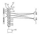
以下に図面を参照しながら本発明の実施の形態について説明する。図3に本発明にかかる立体画像表示装置を示してある。この立体画像表示装置10は、画素毎に反射角の異なる反射板20と、液晶パネル30と、液晶パネルを駆動する制御装置35と、液晶パネルの前面を覆うカバーガラス11とを備えている。反射板20は、入射した光をカバーガラス11に対して垂直方向より左眼1の方向に反射する第1の反射体21と、右眼2の方向に反射する第2の反射体22とを備えている。したがって、第1の反射体21の前方に位置する液晶セル31が左眼用の画像を表示し、第2の反射体22の前方に位置する液晶セル32が右眼用の画像を表示する。
【0019】
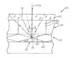
図4に、本例の立体画像表示装置10を拡大して示してある。簡単のためにカバーガラス11と液晶パネル30の屈折率が同一でn(n>1)であるとすると、これらカバーガラス11および液晶パネル30を伝播して反射板20に到達する入射光18とカバーガラス11の法線11aとの角度αは以下の式で限定される。
【0020】
α<arcsin(1/n) ・・・(1)
したがって、右眼用の反射体(反射面)22にカバーガラス11に対し半時計方向にα/2の角度を持たせると、図面上の最も左側(この立体画像表示装置10に対面したときの右側)から角度αで入射した光18は、カバーガラス11の法線方向11aに出力され、それより角度の小さな法線方向11aより左側(対面したときの右側)の光は法線方向11aより左側に反射される。一方、法線方向11aより右側(対面したときの左側)から入射した光は、反射角が角度αより大きくなるので、カバーガラス11で全反射されて出力されない。このように、右眼用の反射体22からはカバーガラス11の法線方向11aより左側(対面したときの右側)にのみ光が出射される。
【0021】
同様に、左眼用の反射体21はカバーガラス11に対して時計方向にα/2の角度を持たせることにより、カバーガラス11の法線方向11より右側(対面したときの左側)にのみ光が出力されるようにすることができる。したがって、本例の立体画像表示装置10においては、左眼の画像を構成する液晶セル21で変調された光は、対面したときの左側に出射され、左眼1にだけ到達する。一方、右眼の画像を構成する液晶セル22で変調された光は、対面したときの右側に出射され、右眼2にだけ到達する。したがって、左眼1および右眼2は、それぞれの画像を捉えることになり、それらが合成されることにより立体感のある画像が知覚される。
【0022】
図5に、液晶パネル30を駆動する制御装置35における処理をブロック図により示してある。制御装置35は、ホストとなるコンピュータやDVD再生装置などから供給された左眼用の画像データφ1と右眼用の画像データφ2を1画面分、記憶するフレームメモリ36aおよび36bを備えている。また、制御装置35は、左眼用の反射体21で出力される左眼用の液晶セル21の画面上の位置を示すアドレスを記憶したアドレスマップ37aと、右眼用の反射体22で出力される右眼用の液晶セル22のアドレスを記憶したアドレスマップ37bとを備えている。そして、アンド回路38aにより左眼用の画像36aと左眼用のアドレスマップ37aとの論理積をとり、立体画像表示装置10のLCD30で表示する左眼用の画像データを生成する。また、アンド回路38bにより右眼用の画像36bと右眼用のアドレスマップ37bとの論理積をとり、立体画像表示装置10のLCD30で表示する右眼用の画像データを生成する。それらの画像データはオア回路39で論理和が取られ、フレームメモリ40にいったん記憶された後にLCD30に出力される。
【0023】
静止画および動画とも同様の構成で、左眼用の画像データφ1および右眼用の画像データφ2から立体画像表示装置10のLCD30で表示する画像データφ0を生成することができる。この方法であると、左眼用の反射体21および右眼用の反射体22の配置によりアドレスマップ37aおよび37bを書き換えることにより、簡単に画像データφ0を形成することができる。
【0024】
反射体21および22の配置は様々なものが考えられる。たとえば、画面上の画素を8列×8行毎の画素クラスタに区分けあるいは分割し、各画素クラスタ内で左眼用の反射体21および右眼用の反射体22が同じ数となるようにランダムに配置することができる。そして、各画素クラスタの配置は異なるようにすれば、画面全体に左眼用の反射体21および右眼用の反射体22をほぼ均等にランダムに分散配置することができ、左眼用のセル31と右眼用のセル32とをほぼ均等にランダムに分散配置できる。このようにセル31および32を配置すると、左眼用の画素と右眼用の画素とが局所的に集中することなく分散配置されるので、縦縞やむらのない画像を表示することができる。画素クラスタを構成する数は8×8に限定されることはなく、各クラスタが人の眼に識別できるサイズ以下であれば良い。
【0025】
さらに、各画素クラスタ毎にセル31および32をモザイク状などに交互に配置することによっても、左眼用の画素と右眼用の画素とが局所的に集中することなく画面上に分散して配置することができる。
【0026】
走査線毎に左眼用セル31と右眼用セル32を交互に配置することによっても、左眼用のセル31と右眼用のセル32とを画面上に均等に分散配置することが可能である。図6に、そのように反射体21および22が配置された立体画像表示装置10の制御装置35の概略構成を示してある。フレームメモリ36aおよび36bにそれぞれ記録された左眼用画像データφ1と右眼画像データφ2とを走査線毎にセレクタ41で選択してデータφ0として供給することによりLCD30を駆動し、立体画像を表示することができる。
【0027】
図7に本発明にかかる立体画像表示装置の異なる例を示してある。この立体画像表示装置15は、反射体20として画素毎に反射角度を変えることができる可動ミラー25を備えている。可動ミラー25は、カバーガラス11に対して反時計方向にα/2傾いた位置(実線で示す第2の反射体22の位置)と、時計方向にα/2傾いた位置(破線で示す第1の反射体21の位置)の2つの位置を安定位置として駆動することができるデジタルマイクロミラーデバイスである。可動ミラー25は、画素毎に独立して動かすことも可能であるが、画面全体の可動ミラー25を同期して動かすことによりフレーム単位で左眼用の画像データと、右眼用の画像データを表示することができる。
【0028】
図8に、そのように駆動する制御装置35の概略構成を示してある。左眼用画像データφ1と右眼用画像データφ2とをフレーム単位でセレクタ42により選択し、可動ミラー25の動きと同期して出力することによりフレーム単位で左眼用画像と右眼用画像をLCD30で表示することができる。フレーム単位で表示された左眼用画像と右眼用画像とをユーザが見ることにより視覚的に合成されるので、立体画像を知覚することができる。
【0029】
左眼用の反射体21としての角度に設定された可動ミラー25と、右眼用の反射体22としての角度に設定された可動ミラー25とを分散配置しておき、フレーム単位で角度を切り替えるように表示することも可能である。この場合、図5に示した制御装置において、左眼用のアドレスマップ37aと右眼用のアドレスマップ37bとをフレーム単位で切り替える必要があるが、これらのアドレスマップ37aおよび37bは共役な関係にあるので、ノット回路を入れて反転するだけで切り替えることが可能である。
【0030】
図9に、本発明の立体画像表示装置のさらに異なる例を示してある。この立体画像表示装置16は、OHPシートのような透明シート50の裏面51に図4に基づき説明した角度の反射体21および22が形成されており、それらの反射体21および22に裏面51からインク59が塗布され反射体21および22に色がつけられている。すなわち、反射体21および22に塗布されたインク59が本例の立体画像表示装置16の変調手段33となる。したがって、左眼用の画像を形成する光束を出射する反射体21に付されたインク59により左眼用の画像が形成され、右眼用の画像を形成する光束を出射する反射体22に付されたインク59により右眼用の画像が形成され、透明シート50の表面52から見ると立体的な画像を知覚することができる。
【0031】
透明シート50に形成された反射体21および22のパターンが予め判明していると、図10に示すような画像処理を行い、インクジェットヘッド58などを有するプリンタで印刷することにより本例の立体画像表示装置を製造することができる。まず、ステップ61で、左眼用画像データと左眼用画素のアドレスマップから左眼用のビットマップを作成し、ステップ62で右眼用画像データと右眼用画素のアドレスマップから右眼用のビットマップを作成する。そして、ステップ63で左眼用のビットマップと右眼用のビットマップを左右逆転して合成し、ステップ64でそのビットマップを印刷データとしてプリンタで印刷する。プリンタで印刷する際は、印刷する位置と反射体21および22の位置を精度良く合致させる必要があるので、シート50にアライメントマークを設けて、プリンタ側で検知させたりする方法を採用することが望ましい。
【0032】
静止画の立体画像を表示する方法としてレンチキュラシートの裏面に印刷する方法がある。しかしながら、レンチキュラシートの場合は、レンズの焦点位置を印刷面とする必要があるので、シートの設計に強度や画素の大きさの制約が多く、高解像度で品質の高い立体画像を表示するものは製造できない。これに対し、本例の立体画像表示装置16であると、レンズやパララクス・バリヤなどの光学素子を前面に配置しないで済むので、左右の画素を一列に並べたり、画素毎の視野が前面に配置された光学素子により限られるなどの画像の品質に影響を及ぼす要素がない。また、前面に光学素子がないので、レンチキュラレンズの焦点距離に印刷するなどの制限もない。したがって、左右の画像を表示する画素を自由に配置することが可能であり、画面全体に均等に配置したり、走査線毎に配置したり、フレーム毎に表示するなど、表示する画像や媒体に合わせて最適な表示方法で立体画像を表示することが可能となる。
【0033】
なお、上述した反射体の傾斜角度α/2は一例であり、傾斜角度をさらに急にすると左眼用の光束はさらに左側に傾いて出射され、右眼用の光束はさらに右側に傾いて出射されるので、それぞれの眼で見るための画像が分離されやすくなる。その一方で、出射される光束の角度範囲が狭まるので光量は減少する方向となる。逆に傾斜角度がα/2より小さくすると、出射角度は広がるので光量は増すが、左右の眼でみる画像が混合される可能性が出てくる。また、カバーガラスにおける全反射を利用して入射および出射光の角度範囲を制限する代わりに、照明用の光源の位置や、フレームなどによって光の入射方向を制限することにより出射される光の方向を制限することも可能である。
【0034】
さらに、左眼用および右眼用の反射体の傾斜はすべて同一である必要はなく、両目の間隔に対して大きな画像を表示する場合は、視角を考慮して反射体の傾斜を変えることが望ましい。また、上記では、平面画像を表示する例を示しているが、両目の間隔に対して大きな画像を表示する装置などにおいては、視角や視線の動きを考慮して反射板や表示パネルを湾曲させることも有効である。
【0035】
【発明の効果】
以上に説明したように、本発明においては、入射光を左眼または右眼方向のいずれか一方に反射する複数の反射体を設け、出射光の指向性をそれらの反射体で制限することにより左眼用画像を左眼に供給し、右眼用画像を右眼に供給するようにしている。したがって、パララクス・バリヤやレンチキュラレンズなどの光学素子を画面の前面に配置しなくても、さらに眼鏡などを用いなくても左眼および右眼用の画像をセパレートして見せることが可能となる。このため、本発明により、画面上に目障りな縦縞が見えず、安価で耐久性があり、さらに信頼性の高い立体画像表示装置を提供することができる。
【図面の簡単な説明】
【図1】パララクス・バリヤを用いた立体画像表示装置の概要を示す図である。
【図2】レンチキュラレンズを用いた立体画像表示装置の概要を示す図である。
【図3】本発明の立体画像表示装置の概要を示す図である。
【図4】図3に示す立体画像表装置の一部を拡大して示す図である。
【図5】立体画像表示装置の制御装置の概略構成を示すブロック図である。
【図6】異なる制御装置の概略構成を示すブロック図である。
【図7】本発明の立体画像表示装置の異なる例を示す図である。
【図8】図7に示す立体画像表示装置の制御装置の概略構成を示す図である。
【図9】本発明の立体画像表示装置のさらに異なる例を示す図である。
【図10】図9に示す立体画像表示装置を印刷する工程を示す図である。
【符号の説明】
1 左眼
2 右眼
10、15、16 立体画像表示装置
11 カバーガラス
20 反射板、21 左眼用の反射体、22 右眼用の反射体
30 液晶パネル(LCD)
31 左眼用の液晶セル、32 右眼用の液晶セル
35 制御装置[0001]
BACKGROUND OF THE INVENTION
The present invention relates to a stereoscopic image display apparatus that performs display that can be grasped as a three-dimensional image.
[0002]
[Prior art]
A binocular stereoscopic image display method is known in which left and right two eyes display different images of the same object recorded from different viewpoints, that is, a left eye image and a right eye image, to be displayed as a stereoscopic image. Several apparatuses or systems have been developed to realize this stereoscopic image display method. A popular method is to display a left-eye image and a right-eye image with different polarizations or colors, and to view stereoscopic images by wearing polarized glasses or color filter glasses. There is also a maintenance separation method using a liquid crystal shutter in the same manner.
[0003]
As a method that does not use glasses, as shown in FIG. 1, images (the
[0004]
As shown in FIG. 2, images (left-
[0005]
[Problems to be solved by the invention]
In these three-dimensional image display methods, first, there is a problem that a method using glasses cannot be seen without glasses. Furthermore, if the left and right images are separately displayed with differently polarized light, the display system becomes complicated and expensive. Also, if the left and right images are displayed in color, the displayable colors are limited, and a multicolor image cannot be displayed.
[0006]
In the system using the parallax barrier, glasses are unnecessary, but the amount of light is reduced by the slit, so it is difficult to make the screen appear bright. In addition, the vertical stripes of the parallax barrier are annoying and the image quality is impaired. If the pitch of the slits is made fine so as to make the vertical stripes unobtrusive, there is a problem that the directivity spreads due to the diffraction phenomenon, and it becomes difficult to separate the left and right images.
[0007]
The fine pitch required for the parallax barrier is derived from the resolution of healthy eyes as follows.
(Pitch) <= (Distance between parallax barrier and eyes) / 3500
For example, when the distance is 35 cm, the maximum pitch is about 100 μm, and the slit width is 10 μm when the pitch is 1/10 of the pitch. Therefore, since it is only about 20 times the visible light, the influence of diffraction cannot be ignored.
[0008]
The method using a lenticular lens also has vertical stripes like the parallax barrier, so the vertical stripes are likely to be obstructive. Furthermore, it is necessary to provide an optical structure such as a lens on the display surface side, that is, the light input / output side (surface). Considering the ease of manufacturing, it is desirable to have a lens structure on the upper surface of the sheet. However, when the lens structure is exposed, there is a problem in terms of durability and reliability. Although it is not impossible to create a protective film on a fine lens structure without impairing the optical characteristics of the lens, it is technically difficult and expensive. There is also a method of creating a lenticular structure by making the structure where lenticulars are transferred upside down on the back of the sheet and filling the space between the sheet and the image with a transparent resin, but it is necessary to place the image on the focal point of the lenticular lens, It is technically difficult to control the resin film thickness.
[0009]
Accordingly, an object of the present invention is to provide a stereoscopic image display apparatus that allows a stereoscopic image to be easily viewed without using glasses or the like and that does not cause annoying vertical stripes.
[0010]
[Means for Solving the Problems]
For this reason, in the present invention, in the reflective image display device, the reflective surface for each pixel constituting the image is set to a different angle for the left eye or the right eye, so that the left eye and the right eye for each pixel. A three-dimensional image is displayed by emitting light beams having different directivities for the eyes. That is, the stereoscopic image display device of the present invention includes a plurality of reflectors that reflect incident light in either the left eye or right eye direction, and a light beam output from these reflectors for the left eye or right eye. And means for modulating the image to be captured. By changing the reflection direction for the left eye and the right eye in pixel units, an image for the right eye and an image for the left eye can be output, so that the display device can be viewed three-dimensionally. Furthermore, since there is no need for a parallax barrier or lenticular lens, there is no risk of vertical stripes.Furthermore, it is possible to arrange the pixels for the right eye and the left eye on the screen without partitioning. You can see seamless 3D images.
[0011]
In order to reflect the left eye and the right eye at different angles, the first reflector set to reflect the incident light in the direction of the left eye and the angle of reflecting the incident light in the direction of the right eye And a second reflector set to be able to be provided. In this stereoscopic image display device, a left-eye image and a right-eye image are output simultaneously. On the other hand, a movable mirror that can reflect incident light by switching between the direction of the left eye and the direction of the right eye can be employed as the reflector. This movable mirror can be provided by adjusting the angular range of movement of the digital micromirror device. In this stereoscopic image display device, the left eye image and the right eye image are alternately displayed.
[0012]
In the stereoscopic image display device having the first and second reflectors, it is desirable that the first and second reflectors are mixed and distributed on the screen. Further, when the first and second reflectors are randomly arranged, the image that can be perceived by the left eye or the right eye is not cut, so that a stereoscopic image display device that is easy to see can be provided.
[0013]
In the stereoscopic image display device in which the first and second reflectors are dispersedly arranged, the logical product of the image for the left eye and the position of the first reflector on the screen is obtained, and the image for the right eye A stereoscopic image can be displayed by taking a logical product with the position of the second reflector on the screen and combining and modulating the logical product to drive the unit. Therefore, the stereoscopic image display apparatus can be driven by a control apparatus having such a function or a control method having such a process.
[0014]
Further, the first and second reflectors can be arranged in line units in the scanning line direction or the like. In the stereoscopic image display apparatus according to the present invention, it is not necessary to dispose an obstacle such as a parallax barrier or a lenticular plate between the means for modulating pixels and both eyes. Even if these pixels are arranged, there is almost no deterioration in image quality. In this stereoscopic image display device, a stereoscopic image can be displayed by driving a means for allocating and modulating the left-eye image and the right-eye image on different scanning lines. Therefore, the stereoscopic image display apparatus can be driven by a control apparatus having such a function or a control method having such a process.
[0015]
Further, in the stereoscopic image display device in which the reflector includes a movable mirror that can switch incident light between the left eye direction and the right eye direction and reflect the incident light, when the left eye image is displayed by the modulating means, When a right-eye image is displayed, a stereoscopic image can be displayed by switching the direction of the movable mirror in synchronization between the left-eye image and the right-eye image. Therefore, the stereoscopic image display apparatus can be driven by a control apparatus having such a function or a control method having such a process.
[0016]
By disposing a transparent cover panel having a constant refractive index, such as glass, on the light input / output side with respect to the reflector, the light totally reflected by the cover panel is not incident or emitted. For this reason, the angle of the light beam that is reflected by the reflector and can be emitted for the left eye or the right eye is limited, so that it is easy to set the angle of the reflector.
[0017]
One of the means for modulating is a light valve such as a liquid crystal panel disposed on the light input / output side with respect to the reflector. Further, one of the means for modulating is a means for changing the color of the reflector or the reflecting surface. For example, a printout capable of displaying a stereoscopic image can be provided by printing the color on the reflector.
[0018]
DETAILED DESCRIPTION OF THE INVENTION
Embodiments of the present invention will be described below with reference to the drawings. FIG. 3 shows a stereoscopic image display apparatus according to the present invention. The stereoscopic
[0019]
FIG. 4 is an enlarged view of the stereoscopic
[0020]
α <arcsin (1 / n) (1)
Therefore, when the right eye reflector 22 (reflecting surface) is provided with an angle of α / 2 in the counterclockwise direction with respect to the
[0021]
Similarly, the
[0022]
FIG. 5 is a block diagram showing processing in the
[0023]
The image data φ0 to be displayed on the
[0024]
Various arrangements of the
[0025]
Furthermore, even if the
[0026]
By alternately arranging the left-
[0027]
FIG. 7 shows a different example of the stereoscopic image display apparatus according to the present invention. The stereoscopic image display device 15 includes a
[0028]
FIG. 8 shows a schematic configuration of the
[0029]
The
[0030]
FIG. 9 shows still another example of the stereoscopic image display apparatus of the present invention. In this stereoscopic
[0031]
When the patterns of the
[0032]
As a method of displaying a stereoscopic image of a still image, there is a method of printing on the back surface of a lenticular sheet. However, in the case of a lenticular sheet, since it is necessary to use the focal point of the lens as the printing surface, there are many restrictions on the strength and pixel size in the sheet design, and those that display a high-resolution and high-quality stereoscopic image It cannot be manufactured. On the other hand, in the stereoscopic
[0033]
The tilt angle α / 2 of the reflector described above is an example, and when the tilt angle is made steeper, the left-eye beam is further tilted to the left and the right-eye beam is tilted to the right. Therefore, images for viewing with each eye are easily separated. On the other hand, since the angular range of the emitted light beam is narrowed, the amount of light decreases. Conversely, when the inclination angle is smaller than α / 2, the emission angle is widened and the amount of light is increased, but there is a possibility that the images seen by the left and right eyes are mixed. Also, instead of using the total reflection on the cover glass to limit the angle range of incident and outgoing light, the direction of the light emitted by limiting the incident direction of the light by the position of the illumination light source or the frame etc. It is also possible to restrict.
[0034]
Furthermore, the tilts of the reflectors for the left eye and the right eye do not have to be the same. When displaying a large image with respect to the distance between both eyes, the tilt of the reflector can be changed in consideration of the viewing angle. desirable. In the above, an example of displaying a planar image is shown. However, in a device that displays a large image with respect to the distance between both eyes, the reflector and the display panel are curved in consideration of the viewing angle and the movement of the line of sight. It is also effective.
[0035]
【The invention's effect】
As described above, in the present invention, by providing a plurality of reflectors that reflect incident light in either the left eye or right eye direction, and restricting the directivity of emitted light by those reflectors, The left eye image is supplied to the left eye, and the right eye image is supplied to the right eye. Therefore, it is possible to separate and display the images for the left eye and the right eye without arranging optical elements such as a parallax barrier or a lenticular lens in front of the screen and without using glasses. For this reason, according to the present invention, it is possible to provide a stereoscopic image display device that does not show annoying vertical stripes on the screen, is inexpensive, durable, and highly reliable.
[Brief description of the drawings]
FIG. 1 is a diagram showing an outline of a stereoscopic image display apparatus using a parallax barrier.
FIG. 2 is a diagram showing an outline of a stereoscopic image display device using a lenticular lens.
FIG. 3 is a diagram showing an outline of a stereoscopic image display apparatus of the present invention.
4 is an enlarged view showing a part of the stereoscopic image table apparatus shown in FIG. 3;
FIG. 5 is a block diagram illustrating a schematic configuration of a control device of the stereoscopic image display device.
FIG. 6 is a block diagram showing a schematic configuration of a different control device.
FIG. 7 is a diagram showing a different example of the stereoscopic image display apparatus of the present invention.
8 is a diagram showing a schematic configuration of a control device of the stereoscopic image display device shown in FIG.
FIG. 9 is a diagram showing still another example of the stereoscopic image display apparatus of the present invention.
10 is a diagram showing a process of printing the stereoscopic image display device shown in FIG. 9. FIG.
[Explanation of symbols]
DESCRIPTION OF SYMBOLS 1
31 Liquid crystal cell for left eye, 32 Liquid crystal cell for
Claims (6)
Translated fromJapanese前記反射体は、前記入射光を左眼の方向に反射する角度に設定された第1の反射体と、前記入射光を右眼の方向に反射する角度に設定された第2の反射体とを備え、
前記第1および第2の反射体が混合され画面上に分散配置され、
さらに、左眼用の画像と前記第1の反射体の画面上の位置との論理積をとり、右眼用の画像と前記第2の反射体の画面上の位置との論理積をとり、それらの論理積を合成して前記変調する手段を駆動する制御手段を有する立体画像表示装置。A plurality of reflectors that reflect incident light in either the left eye or right eye direction, and means for modulating the light beam output from these reflectors into an image that is captured by either the left eye or the right eye A stereoscopic image display device comprising:
The reflector includes a first reflector set to an angle that reflects the incident light toward the left eye, and a second reflector set to an angle that reflects the incident light toward the right eye; With
The first and second reflectors are mixed and distributed on the screen;
Further, the logical product of the image for the left eye and the position of the first reflector on the screen is taken, the logical product of the image for the right eye and the position of the second reflector on the screen is taken, A stereoscopic image display device having a control means for driving the means for synthesizing these logical products.
左眼用の画像と前記第1の反射体の画面上の位置との論理積をとり、右眼用の画像と前記第2の反射体の画面上の位置との論理積をとり、それらの論理積を合成して前記変調する手段を駆動する工程を有する立体画像表示装置の制御方法。A plurality of reflectors that reflect incident light in either the left eye or right eye direction, and means for modulating the light beam output from these reflectors into an image that is captured by either the left eye or the right eye The reflector has a first reflector set at an angle that reflects the incident light in the direction of the left eye, and a first reflector set at an angle that reflects the incident light in the direction of the right eye. 2, and a control method of a stereoscopic image display device in which the first and second reflectors are mixed and distributed on the screen.
The logical product of the image for the left eye and the position of the first reflector on the screen is taken, the logical product of the image for the right eye and the position of the second reflector on the screen is taken, and those A method for controlling a stereoscopic image display apparatus, comprising a step of synthesizing logical products and driving the means for modulating.
Priority Applications (1)
| Application Number | Priority Date | Filing Date | Title |
|---|---|---|---|
| JP2002061099AJP3960085B2 (en) | 2002-03-06 | 2002-03-06 | Stereoscopic image display device |
Applications Claiming Priority (1)
| Application Number | Priority Date | Filing Date | Title |
|---|---|---|---|
| JP2002061099AJP3960085B2 (en) | 2002-03-06 | 2002-03-06 | Stereoscopic image display device |
Publications (2)
| Publication Number | Publication Date |
|---|---|
| JP2003255265A JP2003255265A (en) | 2003-09-10 |
| JP3960085B2true JP3960085B2 (en) | 2007-08-15 |
Family
ID=28670195
Family Applications (1)
| Application Number | Title | Priority Date | Filing Date |
|---|---|---|---|
| JP2002061099AExpired - Fee RelatedJP3960085B2 (en) | 2002-03-06 | 2002-03-06 | Stereoscopic image display device |
Country Status (1)
| Country | Link |
|---|---|
| JP (1) | JP3960085B2 (en) |
Cited By (1)
| Publication number | Priority date | Publication date | Assignee | Title |
|---|---|---|---|---|
| CN103185293A (en)* | 2011-12-29 | 2013-07-03 | 上海天马微电子有限公司 | Reflecting plate and total reflection 3D display device |
Families Citing this family (5)
| Publication number | Priority date | Publication date | Assignee | Title |
|---|---|---|---|---|
| DE10344323A1 (en)* | 2003-09-22 | 2005-04-21 | X3D Technologies Gmbh | Method and arrangement for spatial representation |
| JP3701661B2 (en) | 2003-12-05 | 2005-10-05 | シャープ株式会社 | Display panel and display device |
| GB2428129A (en)* | 2005-07-08 | 2007-01-17 | Sharp Kk | A multiple-view directional display |
| JP2009080384A (en)* | 2007-09-27 | 2009-04-16 | Seiko Epson Corp | Electro-optical device and electronic apparatus |
| CN109426026B (en) | 2017-09-05 | 2022-08-23 | 京东方科技集团股份有限公司 | Display panel, preparation method thereof and display device |
- 2002
- 2002-03-06JPJP2002061099Apatent/JP3960085B2/ennot_activeExpired - Fee Related
Cited By (2)
| Publication number | Priority date | Publication date | Assignee | Title |
|---|---|---|---|---|
| CN103185293A (en)* | 2011-12-29 | 2013-07-03 | 上海天马微电子有限公司 | Reflecting plate and total reflection 3D display device |
| CN103185293B (en)* | 2011-12-29 | 2015-03-18 | 上海天马微电子有限公司 | Reflecting plate and total reflection 3D display device |
Also Published As
| Publication number | Publication date |
|---|---|
| JP2003255265A (en) | 2003-09-10 |
Similar Documents
| Publication | Publication Date | Title |
|---|---|---|
| JP3788787B2 (en) | Parallax optical device and autostereoscopic display device | |
| US7190518B1 (en) | Systems for and methods of three dimensional viewing | |
| JP3930021B2 (en) | Display device and electronic apparatus equipped with display device | |
| US7259898B2 (en) | Direct view LC display | |
| JP4367775B2 (en) | Dual view display | |
| US6929369B2 (en) | Autostereoscopic display | |
| JP5649526B2 (en) | Display device | |
| CN104685867B (en) | Observer tracks automatic stereoscopic display device | |
| US8502761B2 (en) | Transparent component with switchable reflecting elements, and devices including such component | |
| US7639210B2 (en) | Multi-depth displays | |
| JP4333878B2 (en) | Multi-view directional display | |
| JP3642736B2 (en) | Directional display | |
| JPH11285030A (en) | Stereoscopic image display method and stereoscopic image display device | |
| JP2007535685A (en) | Pixel layout for autostereoscopic display | |
| JP7497733B2 (en) | Image display device | |
| US5828495A (en) | Lenticular image displays with extended depth | |
| US20150177608A1 (en) | Auto stereoscopic projector screen | |
| JP4503619B2 (en) | Portable device | |
| JP4703477B2 (en) | 3D display device | |
| KR20080003087A (en) | Stereoscopic Display Using Reflector | |
| JP4213210B2 (en) | 3D observation and projection system | |
| JP3789332B2 (en) | 3D display device | |
| JP2008541165A (en) | 3D image display device using flat panel display | |
| JP3960085B2 (en) | Stereoscopic image display device | |
| JP3739348B2 (en) | 3D display device |
Legal Events
| Date | Code | Title | Description |
|---|---|---|---|
| A621 | Written request for application examination | Free format text:JAPANESE INTERMEDIATE CODE: A621 Effective date:20050218 | |
| A977 | Report on retrieval | Free format text:JAPANESE INTERMEDIATE CODE: A971007 Effective date:20070110 | |
| A131 | Notification of reasons for refusal | Free format text:JAPANESE INTERMEDIATE CODE: A131 Effective date:20070123 | |
| A521 | Written amendment | Free format text:JAPANESE INTERMEDIATE CODE: A523 Effective date:20070326 | |
| RD04 | Notification of resignation of power of attorney | Free format text:JAPANESE INTERMEDIATE CODE: A7424 Effective date:20070402 | |
| TRDD | Decision of grant or rejection written | ||
| A01 | Written decision to grant a patent or to grant a registration (utility model) | Free format text:JAPANESE INTERMEDIATE CODE: A01 Effective date:20070424 | |
| A61 | First payment of annual fees (during grant procedure) | Free format text:JAPANESE INTERMEDIATE CODE: A61 Effective date:20070507 | |
| R150 | Certificate of patent or registration of utility model | Free format text:JAPANESE INTERMEDIATE CODE: R150 | |
| FPAY | Renewal fee payment (event date is renewal date of database) | Free format text:PAYMENT UNTIL: 20110525 Year of fee payment:4 | |
| FPAY | Renewal fee payment (event date is renewal date of database) | Free format text:PAYMENT UNTIL: 20120525 Year of fee payment:5 | |
| FPAY | Renewal fee payment (event date is renewal date of database) | Free format text:PAYMENT UNTIL: 20120525 Year of fee payment:5 | |
| FPAY | Renewal fee payment (event date is renewal date of database) | Free format text:PAYMENT UNTIL: 20130525 Year of fee payment:6 | |
| FPAY | Renewal fee payment (event date is renewal date of database) | Free format text:PAYMENT UNTIL: 20140525 Year of fee payment:7 | |
| S531 | Written request for registration of change of domicile | Free format text:JAPANESE INTERMEDIATE CODE: R313531 | |
| R350 | Written notification of registration of transfer | Free format text:JAPANESE INTERMEDIATE CODE: R350 | |
| LAPS | Cancellation because of no payment of annual fees |